

Page 1

Watson-Marlow qdos
User Manual
m-qdos-en-02 1
Page 2

Contents
1 Declaration of conformity 5
2 Warranty 6
2.1 Conditions 6
2.2 Exceptions 7
3 When you unpack your pump 8
3.1 Packaging disposal 8
3.2 Inspection 8
3.3 Components supplied 8
3.4 Optional accessories 9
3.5 Storage 9
4 Information for returning pumps 10
5 Safety notes 11
6 Pump specifications 13
6.1 Pump specifications 15
6.2 Standards (ACmains power supply) 16
6.3 Standards (12-24V DC power supply) 17
6.4 Dimensions 18
6.5 Weights 19
7 Good pump installation practice 20
7.1 General recommendations 20
7.2 Do's and do not's 21
7.3 Pressure capability 21
7.4 Dry running 21
8 Connecting to a power supply 22
8.1 AC mains power supply 22
8.2 DC power supply option 23
9 Start-up check list 24
10 Automatic control wiring - Universal, Universal+ and Remote models
without relay modules 25
10.1 Input pin assignments at the pump 26
10.2 Optional input lead 26
10.3 Output pin assignments at the pump 27
10.4 Optional output lead 29
11 Automatic control wiring - 24V relay module and 110V relay module
(Universal and Universal+ only) 30
11.1 Module: cover removal and refitting 30
11.2 Wiring up the terminal connectors 31
11.3 24Vrelay module pcb connectors 34
m-qdos-en-02 2
Page 3

11.4 110V relay module pcb connectors 37
12 PROFIBUS control wiring 40
12.1 PROFIBUS installation 40
12.2 Pin assignments at the pump 41
13 Switching on (Manual, PROFIBUS, Universal and Universal+) 42
13.1 Switching on the pump for the first time (Manual, PROFIBUS, Universal and
Universal+ only) 42
13.2 Switching the pump on in subsequent power cycles (Manual, PROFIBUS,
Universal and Universal+ only) 44
14 Switching on (Remote) 45
15 Pump operation 46
15.1 Pump operation (Remote pump) 46
15.2 Pump operation (Manual, PROFIBUS, Universal and Universal+ only) 46
16 Manual mode (Manual, PROFIBUS, Universal and Universal+ only) 49
17 PROFIBUS mode(PROFIBUS only) 52
17.1 Assigning the PROFIBUS station address at the pump 53
17.2 PROFIBUS communication errors 55
17.3 PROFIBUS GSD file 56
17.4 User Parameter Data 58
17.5 PROFIBUS data exchange 59
17.6 Device-related diagnostic data 62
17.7 Channel-related diagnostic data 62
18 Flow calibration mode (Manual, PROFIBUS, Universal and Universal+ only) 64
19 Analog 4-20mA mode (Universal and Universal+ only) 67
19.1 Calibrate the pump for 4-20mA control (Universal+ only) 72
20 Contact Mode (All Universal and Universal+ models except 110V relay
versions) 77
20.1 Contact settings 77
20.2 Contact operating mode (All Universal and Univ ersal+ models except 110V
relay versions) 79
20.3 Fluid recovery mode (Manual, PROFIBUS, Universal and Universal+ only) 80
20.4 Remote fluid recovery (Universal and Universal+ models without relay
modules) 82
21 Main menu (Manual, PROFIBUS, Universal and Universal+ only) 84
21.1 Fluid level monitor (Manual, PROFIBUS, Universal and Universal+ only) 85
21.2 Security settings (Manual, PROFIBUS, Universal and Universal+ only) 89
21.3 General settings (Manual, PROFIBUS, Universal and Universal+ only) 92
21.4 MODE menu (Manual, PROFIBUS, Universal and Universal+ only) 97
21.5 Control settings (Manual, PROFIBUS, Universal and Universal+ only) 98
21.6 Help (Manual, PROFIBUS, Universal and Universal+ only ) 105
m-qdos-en-02 3
Page 4

22 Status LEDs (Remote only) 106
23 Troubleshooting 107
23.1 Leak detection 107
23.2 Error codes 108
23.3 Error Indication (Remote only) 109
24 Technical support 110
25 Drive maintenance 111
26 Pumphead Replacement (qdos 30) 112
26.1 Connecting interface tubing 115
27 Pumphead Replacement (qdos 20, 60 and 120) 117
27.1 Connecting interface tubing 120
28 Ordering information 123
28.1 Pump part numbers 123
28.2 Spares and accessories 124
29 Performance data 127
29.1 Pumping conditions 127
29.2 Pressure capability 127
29.3 Dry running 127
29.4 Pumphead life 127
29.5 DC power supply option - input characteristics 127
29.6 Performance curves 128
30 Trademarks 129
31 Publication history 130
m-qdos-en-02 4
Page 5

1 Declaration of conformity
This pump is ETL listed: ETL control number 3050250. Cert to CAN/CSA std C22.2
No 61010-1. Conforms to UL std 61010A-1.
See "Pump specifications" on page13.
m-qdos-en-02 5
Page 6

2 Warranty
Watson-Marlow Limited (“Watson-Marlow”) warrants this product to be free from defects in
materials and workmanship for three years from the date of shipment, under normal use
and service.
Watson- Marlow’s sole responsibility and the customer’s exclusive remedy for any claim
arising out of the purchase of any product from Watson- Marlow is, at Watson Marlow’s
option: repair, replacement or credit, where applicable.
Unless otherwise agreed in writing, the foregoing warranty is limited to the country in
which the product is sold.
No employee, agent or representative of Watson-Marlow has the authority to bind WatsonMarlow to any warranty other than the foregoing unless in writing and signed by a director
of Watson-Marlow. Watson-Marlow makes no warranty of the fitness of its products for a
particular purpose.
In no event:
i. shall the cost of the customer’s exclusive remedy exceed the purchase price of the
product;
ii. shall Watson-Marlow be liable for any special, indirect, incidental, consequential,
or exemplary damages, however arising, even if Watson-Marlow has been advised
of the possibility of such damages.
Watson-Marlow shall not be liable for any loss, damage, or expense directly or indirectly
related to or arising out of the use of its products, including damage or injury caused to
other products, machinery, buildings, or property. Watson-Marlow shall not be liable for
consequential damages, including, without limitation, lost profits, loss of time,
inconvenience, loss of product being pumped, and loss of production.
This warranty does not obligate Watson-Marlow to bear any costs of removal, installation,
transportation, or other charges which may arise in connection with a warranty claim.
Watson-Marlow shall not be responsible for shipping damage of returned items.
2.1 Conditions
l Products must be returned by pre-arrangement to Watson-Marlow, or a Watson-Marlow
approved service centre.
l All repairs or modifications must have been made by Watson- Marlow Limited, or a
Watson-Marlow approved service centre or with the express permission in writing of
Watson-Marlow, signed by a manager or director of Watson-Marlow.
l Any remote control or system connections must be made in accordance to Watson-
Marlow recommendations.
l All PROFIBUS systems must be installed or certified by a PROFIBUS approved installation
engineer.
m-qdos-en-02 6
Page 7

2.2 Exceptions
l Consumable items including tubing and pumping elements are excluded.
l Pumphead rollers are excluded.
l Repairs or service necessitated by normal wear and tear or by lack of reasonable and
proper maintenance are excluded.
l Products which, in the judgement of Watson-Marlow, have been abused, misused, or
subjected to malicious or accidental damage or neglect are excluded.
l Failure caused by electrical surge is excluded.
l Failure caused by incorrect or sub-standard system wiring is ex cluded.
l Damage by chemical attack is excluded.
l Ancillaries such as leak detectors are excluded.
l Failure caused by UV light or direct sunlight.
l All ReNu pumpheads are excluded.
l Any attempt to disassemble a Watson- Marlow product will invalidate the product
warranty.
Watson-Marlow reserves the right to amend these terms and conditions at any time.
m-qdos-en-02 7
Page 8

3 When you unpack your pump
Unpack all parts carefully, retaining the packaging until you are sure all components are
present and in good order. Check against the components supplied list, below.
3.1 Packaging disposal
Dispose of packaging materials safely, and in accordance with regulations in your area. The
outer carton is made of corrugated cardboard and can be recycled.
3.2 Inspection
Check that all components are present. Inspect components for damage in transit. If
anything is missing or damaged, contact your distributor immediately.
3.3 Components supplied
Qdos 20, 60 and 120:
m-qdos-en-02 8
Page 9

Qdos 30:
Note: The appearance of the pump drive unit may vary from the that shown depending on
the pump model. The hydraulic connector pack shown is an optional accessory.
The following components are supplied with all qdos pumps:
l Pump drive unit
l ReNu pumphead
l User connection collars
l The designated power cable (attached to the pump drive unit)
l CD-ROM containing these operating instructions
l Quick start manual
l Product safety information booklet
3.4 Optional accessories
Spares and accessories are available such as:
l Additional ReNu pumphead
l HMI protective cover (not compatible with remote models)
l Interface tubing
l Input and output (I/O) leads
ll Hydraulic connector packs
For a full list of accessories see "Spares and accessories" on page124.
3.5 Storage
This product has an extended shelf life. However, care should be taken after storage to
ensure that all parts function correctly. Please observe the storage recommendations and
use-by dates which apply to ReNu pumpheads and tubing you may wish to bring into
service after storage.
m-qdos-en-02 9
Page 10

4 Information for returning pumps
In compliance with the UK Health and Safety at Work Act and the Control of Substances
Hazardous to Health Regulations, you are required to declare the substances which have
been in contact with product (s) you return to Watson- Marlow or its subsidiaries or
distributors. Failure to do so will cause delays. Please ensure that you fax us this form and
receive an RGA (Returned Goods Authorisation) before you despatch the product (s). A copy
of this form must be attached to the outside of the packaging containing the product(s).
Please complete a separate decontamination declaration for each product. A copy of the
appropriate decontamination declaration can be downloaded from the Watson- Marlow
website at: www.wmftg.com/decon.
You are responsible for cleaning and decontaminating the product(s) before return.
m-qdos-en-02 10
Page 11

5 Safety notes
In the interests of safety, this pump and pumphead should only be used by competent,
suitably trained personnel after they have read and understood this manual, and
considered any hazard involved. If the pump is used in a manner not specified by WatsonMarlow Limited, the protection provided by the pump may be impaired.
Any person who is involved in the installation or maintenance of this equipment should be
fully competent to carry out the work. In the UK this person should also be familiar with the
Health and Safety at Work Act 1974.
This symbol, used on the pump and in this manual, means: Caution,
refer to accompanying documents.
This symbol, used on the pump and in this manual, means: Do not
allow fingers to contact moving parts.
This symbol, used on the pump and in this manual, means: Caution,
hot surface.
Fundamental work with regard to lifting, transportation, installation,
starting-up, maintenance and repair should be performed by qualified
personnel only. The unit must be isolated from mains power while
work is being carried out. The motor must be secured against
accidental start-up.
There is a non-replaceable fuse on the switch-mode power supply
board. In some countries, the mains power plug contains a
replaceable fuse. There are no user-serviceable fuses or parts inside
this pump.
This pump must be used only for its intended purpose.
The pump must be accessible at all times to facilitate operation and maintenance. Access
points must not be obstructed or blocked. Do not fit any devices to the drive unit other
than those tested and approved by Watson- Marlow. Doing so could lead to injury to
persons or damage to property for which no liability can be accepted.
If hazardous fluids are to be pumped, safety procedures specific to the particular fluid and
application must be put in place to protect against injury to persons.
This product does not comply with the ATEX directive and must not be
used in explosive atmospheres.
m-qdos-en-02 11
Page 12

If pumping flammable liquids, a full risk assessment should be
completed prior to use.
The exterior surfaces of the pump may get hot during operation. Do
not take hold of the pump while it is running. Allow the pump to cool
after use before handling. The drive unit must not be run without a
pumphead fitted. The pumphead should not be run dry for extended
periods of time. The pump should not be used to pump fluids where
the temperature of the fluid can reach temperatures of more than
70°C.
Ensure the chemicals to be pumped are compatible with the
pumphead, lubricant, tubing, pipework and fittings to be used with
the pump. Please refer to the chemical compatibility guide which can
be found at: www.wmpg.com/chemical If you need to use the pump
with any other chemical please contact Watson-Marlow to confirm
compatibility
Operation of the pump after failure of the consumable peristaltic tube may result in a flow
of chemicals to the inside of the pumphead. Some aggressive chemicals are not compatible
with the pumphead materials. These aggressive chemicals will react to the matierials
internal to the pumphead and may cause leaks.
In the worst case, chemicals could leak out from the pumphead and attack the drive shaft
and lip seal, damaging the seal integrity. Damage to the seal could cause aggressive
chemicals to enter the pump housing and react wth the components internal to the pump
housing. The reaction may produce explosive gases inside the pump housing.
Danger of damage to pump and possible risk of explosion if dosing
liquid has entered the pump housing.
To prevent dosing liquid entering the pump housing follow the
recommended actions below.
In the event of tube failure the pump should be isolated from both
electrical and hydraulic supplies prior to pumphead replacement (See
"Pumphead Replacement (qdos 30)" on page112 or "Pumphead
Replacement (qdos 20, 60 and 120)" on page117.)
To prevent damage to the pump and pumphead due to failure of the consumable peristaltic
tube:
• change the pumphead shortly after failure
• install a non return valve in the discharge line close to the pump when pumping
against a positive pressure. This will prevent a constant stream of chemical flowing
back into the pumphead after failure
• consider using an electrical interlock to isolate the power to the pump, this can be
controlled by the pump alarm signal when a leak is detected by the pump
• do not disable the pump leak detection system
• change the pumphead prior to failure when pumping very aggressive chemicals that
are not compatible with the pumphead materials. There are volume and hours
counters in the product to provide indication of consumable life.
m-qdos-en-02 12
Page 13

6 Pump specifications
qdos 20, 60 and 120:
ReNu pumphead
(left hand mounted)
Pumphead locking
latch
Outlet
Inlet
Mounting plate
HMI
(not Remote)
Drive unit
qdos 20, 60 and 120 with relay module:
ReNu pumphead
(left hand mounted)
Pumphead locking
latch
Outlet
Inlet
Mounting plate
110v or 24v relay
module
HMI
(not Remote)
Drive unit
m-qdos-en-02 13
Page 14

qdos 30:
ReNu pumphead
(left hand mounted)
Pumphead retaining
clamps
Outlet
Inlet
Power
Mounting plate
HMI
(not Remote)
Drive unit
qdos 30 with 110v or 24v relay module:
pumphead retaining
clamps
ReNu pumphead
(left hand mounted)
Outlet
Inlet
Power
Mounting plate
110V or 24V relay
module
HMI
(not Remote)
Drive unit
m-qdos-en-02 14
Page 15

A nameplate is fixed to the rear of the pump. It contains manufacturer and contact details,
product reference number, serial number and model details.
0M0.223L.GLU Iss 1
qdos Manual 30l/hr 7bar
190gpd 100psi Sant PFPE
Serial Number
Manufacturer details
Product reference
Model
Serial number
6.1 Pump specifications
Flow Range (flow control)
Manual, PROFIBUS, Universal and
Universal+:
qdos120:0.1-2000 ml/min (20000:1)
qdos60:0.1-1000 ml/min (10000:1)
qdos30:0.1-500 ml/min (5000:1)
qdos20:0.1-333 ml/min (3330:1)
Remote:
qdos120:1.25-2000 ml/min (1600:1)
qdos60:0.6-1000 ml/min (1600:1)
qdos30:0.3-500 ml/min (1600:1)
qdos20:0.2-333 ml/min (1600:1)
AC Supply voltage/frequency ~100-240V 50/60Hz
m-qdos-en-02 15
Page 16

AC Power consumption 190VA
DC Supply voltage/frequency
(12/24VDC power option)
12-24V DC
DC Power consumption (12/24VDC
power option)
150W
Installation category (overvoltage
category)
II
±10% of nominal voltage. Maximum
voltage fluctuation
An electrical mains supply is required
along with cable connections to the best
practice of noise immunity
Enclosure rating
IP66 to BS EN 60529
NEMA 4X to NEMA 250*
Operating temperature range 4°C to 45°C, 41°F to 113°F
Storage temperature range -20°C to 70°C, -4°F to 158°F
Maximum altitude 2,000m, 6,560ft
Humidity (non-condensing)
80% up to 31°C, 88°F, decreasing linearly
to 50% at 40°C, 104°F
Pollution degree 2
Noise <70dB(A) at 1m
*Requires the fitting of the HMI protective cover.
6.2 Standards (ACmains power supply)
EC Harmonised
standards
Safety requirements for electrical equipment for measurement,
control and laboratory use: BS EN 61010- 1 incorporating A2
Category 2, Pollution degree 2
Degrees of protection provided by enclosures (IP code): BS EN
60529 amendments 1 and 2
EN61326-1:2006 Electrical Equipment for measurement control
and laboratory use EMC requirements Part 1
m-qdos-en-02 16
Page 17

Other Standards
UL 61010A-1, UL/CSA 61010-1
CAN/CSA-C22.2 No 61010-1
IEC 61010-1
Radiated emissions FCC 47CFR, Part 15
NEMA 4X to NEMA 250
NSF61 for pumphead
6.3 Standards (12-24V DC power supply)
EC Harmonised
standards
Safety requirements for electrical equipment for measurement,
control and laboratory use: BS EN 61010- 1 incorporating A2
Category 2, Pollution degree 2
Degrees of protection provided by enclosures (IP code): BS EN
60529 amendments 1 and 2
EN61326-1:2006 Electrical Equipment for measurement control
and laboratory use EMC requirements Part 1
Other Standards
UL 61010A-1, UL/CSA 61010-1
CAN/CSA-C22.2 No 61010-1
IEC 61010-1
Radiated/conducted emissions FCC 47CFR, Part 15
NEMA 4X to NEMA 250
NSF61 for pumphead
m-qdos-en-02 17
Page 18

6.4 Dimensions
A
B
C
D
F
G
H
I
E*
Dimension qdos20 qdos30 qdos60 qdos120
A 234mm (9.2”) 234mm (9.2”) 234mm (9.2”) 234mm (9.2”)
B 214mm (8.4”) 214mm (8.4”) 214mm (8.4”) 214mm (8.4”)
C 118mm (4.6”)
82.5mm
(3.2”)
118mm (4.6”) 118mm (4.6”)
D
266mm
(10.5”)
233mm (9.2”)
266mm
(10.5”)
266mm (10.5”)
E*—Optional relay modules (H or
R)
43mm (1.7”) 43mm (1.7”) 43mm (1.7”) 43mm (1.7”)
F 173mm (6.8”) 173mm (6.8”) 173mm (6.8”) 173mm (6.8”)
G 40mm (1.6”) 40mm (1.6”) 40mm (1.6”) 40mm (1.6”)
H 140mm (5.5”) 140mm (5.5”) 140mm (5.5”) 140mm (5.5”)
I 10mm (0.4”) 10mm (0.4”) 10mm (0.4”) 10mm (0.4”)
m-qdos-en-02 18
Page 19

6.5 Weights
qdos20, 60 and 120:
Model
Drive Drive with pumphead
kg lb kg lb
Manual 4.6 10lb 2oz 5.7 12lb 9oz
Remote 4.5 9lb 15oz 5.6 12lb 6oz
Universal 4.6 10lb 2oz 5.7 12lb 9oz
Universal+ 4.6 10lb 2oz 5.7 12lb 9oz
PROFIBUS 4.6 10lb 2oz 5.7 12lb 9oz
Universal 24V relay 4.8 10lb 9oz 5.9 13lb 0oz
Universal+ 24V relay 4.8 10lb 9oz 5.9 13lb 0oz
Universal 110V relay 4.8 10lb 9oz 5.9 13lb 0oz
Universal+ 110V relay 4.8 10lb 9oz 5.9 13lb 0oz
qdos30:
Model
Drive Drive with pumphead
kg lb kg lb
Manual 4.1 9lb 5.05 11lb 2oz
Remote 4.0 8lb 13oz 4.95 10lb 15oz
Universal 4.1 9lb 5.05 11lb 2oz
Universal+ 4.1 9lb 5.05 11lb 2oz
PROFIBUS 4.1 9lb 5.05 11lb 2oz
Universal 24V relay 4.3 9lb 8oz 5.25 11lb 9oz
Universal+ 24V relay 4.3 9lb 8oz 5.25 11lb 9oz
Universal 110V relay 4.3 9lb 8oz 5.25 11lb 9oz
Universal+ 110V relay 4.3 9lb 8oz 5.25 11lb 9oz
m-qdos-en-02 19
Page 20

7 Good pump installation practice
7.1 General recommendations
Always consult an expert before installing a metering pump in a
specialised system. Metering pumps should be maintained by
qualified persons.
The pump must be bolted to a flat, horizontal, rigid surface, free from excessive vibration,
to ensure correct lubrication of the gearbox and correct pumphead operation. Allow a free
flow of air around the pump to ensure that heat can be dissipated. Ensure that the ambient
temperature around the pump does not exceed 45°C (113°F).
The STOP key on pumps supplied with a keypad will alway s stop the pump. However, it is
recommended that a suitable local emergency stop device is fitted into the mains supply to
the pump.
Do not stack pumps.
This pump is self-priming and self-sealing against backflow. No valves are required in inlet
or discharge lines, except as described below. Valves in the process flow must be opened
before the pump operates.
Users must fit a non-return valve between the pump and the
discharge pipework to avoid the sudden release of pressurised fluid
in the event of a pumphead failure. This shall be fitted immediately
after the discharge of the pump.
qdos is a positive displacement pump; therefore, it is recommended
best practice that customers incorporate discharge pressure relief in
their piping system. Failure to fit a pressure release valve in the
discharge pipework will result in excessive build up of pressure
should the discharge become blocked. This may present a safety risk,
may cause damage to the system pipework or lead to premature
failure of the pump head. The pressure relief valve shall be rated at no
more than 10 bar. It shall always be rated at below the users system
maximum operating pressure. It shall be installed so as to provide
easy access for maintenance, inspection and repair. It shall not be
capable of being adjusted without the use of a tool. The discharge
opening must be located and directed so that the release material is
not directed towards any person and will not deposit on parts that
could cause a hazard. There must not be a shut-off valve between the
overpressure safety device and the pump.
Do not block the drain port of the ReNu pumphead.
Ensure the chemicals to be pumped are compatible with the
pumphead and the pipework and fittings to be used with the pump.
Please refer to the chemical compatibility guide which can be found at:
www.wmftg.com/chemical. If you need to use the pump with any
other chemical please contact Watson-Marlow to confirm compatibility.
m-qdos-en-02 20
Page 21

7.2 Do's and do not's
Do not build a pump into a tight location without adequate airflow around the pump.
Do keep delivery and suction tubes as short and direct as possible - though ideally not
shorter than one metre - and follow the straightest route. Use bends of large radius: at
least four times the tubing diameter. Ensure that connecting pipework and fittings are
suitably rated to handle the predicted pipeline pressure. Avoid pipe reducers and lengths of
smaller bore tubing than the pumphead section, particularly in pipelines on the suction
side. Any valves in the pipeline must not restrict the flow. Any valves in the flow line must
be open when the pump is running.
Do use suction and delivery pipes with the largest diameter bore tube that will fit with
your process, especially when pumping viscous product. Care should be taken when
pumping solids in suspension as large bore tubes will reduce the fluid velocity, this may
lead to solids dropping out of suspension.
Do site the pump at or just below the level of the fluid to be pumped if possible. This will
ensure flooded suction and maximum pumping efficiency.
Do run at slow speed when pumping viscous fluids. Flooded suction will enhance pumping
performance, particularly for materials of a viscous nature.
Do recalibrate after changing pumphead, fluid, or any connecting pipework. It is also
recommended that the pump is recalibrated periodically to maintain accuracy.
Do ensure your PROFIBUS pump is installed in accordance with PROFIBUS installation
guidelines.
Do not pump any chemical not compatible with the pumphead.
Do not tilt the drive with a pumphead fitted, even if it is not running.
Do not strap the control and mains cable together.
Do avoid tight bends in the PROFIBUS signal cable.
7.3 Pressure capability
qdos120 can be operated continuously at discharge pressures of up to 4 bar (60psi)
qdos20, qdos30 and qdos60 can be operated continuously at discharge pressures of up to 7
bar (100psi).
qdos30 can be operated at discharge pressures of up to 10 bar (145 psi), however flowrate
and pumphead life will be affected.
7.4 Dry running
qdos will continue to operate when there is gas present in the suction line and will
maintain prime in these conditions. The pump can be run dry, however flow rate and
pumphead life will be affected.
m-qdos-en-02 21
Page 22

8 Connecting to a power supply
8.1 AC mains power supply
This pump is fitted with a switch mode power supply and will operate from any mains
voltage in the range ~100-240V AC, 50/60Hz supplies.
Make suitable connection to an earthed, single-phase mains electricity supply.
We recommend using commercially available supply voltage surge
suppression where electrical noise may be present.
Power cable: The pump is supplied fitted with a cable gland and approximately 2.8m
(9.2ft) of power cable. The cable is not user-detachable and the entry gland at the front of
the pump should not be disassembled.
Each pump is supplied with a power cable. The connector at the pump end of the cable is
IP66 rated. The mains plug at the opposite end of the cable is NOT IP66 rated.
Ensure that all power supply cables are adequately rated for the
equipment.
The pump must be positioned so that the disconnection device (the
mains plug), is easily accessible when the equipment is in use.
When PAT testing this unit ensure that the earth bond test terminal is
used. Do not use the motor shaft as this could result in motor bearing
damage and reduce long term reliability.
Earth bond test terminal position
m-qdos-en-02 22
Page 23

8.2 DC power supply option
The range of DC sources is intended to include:
• Automotive— either mobile, such as trailer mounted, or static, such as a vehicle
battery or auxiliary output
• Conventional DCsupplies derived from AC mains, such as 12V or 24V supplies
powering PLCs
• Solar panels with any type of back-up battery within the input range
• Other renewable energy generators such as wind/hydro turbines with any type of
back up battery within the input range
Power cable: The pump is supplied fitted with a cable gland and approximately 2.0m
(6.6ft) of power cable and an IP31 splash proof blade fuse holder and 20A blade fuse. The
cable is not user-detachable and the entry gland at the front of the pump should not be
disassembled.
Notes
It is highly recommended that an isolating switch is provided between the power source
and the pump. The cable is fitted with M8 ring terminals to fit common isolators.
The 20A blade fuse is a safety device and should not be removed or the value changed.
The fuse holder is splashproof (IP31) but NOTwaterproof (IP66). Connection to the DC
source should be provided with appropriate IP protection.
Large start up currents may be required, especially at low voltages, see "Performance
data" on page127 for correct selection of power source.
We DO NOT recommend increasing the cable length when used in 12V systems due to
extra voltage loss in the cable. Increasing cable length will also invalidate the pumps EMC
compliance and require the user to perform their own system level EMC compliance check.
m-qdos-en-02 23
Page 24

9 Start-up check list
l Fit the pumphead to the drive. (See "Pumphead Replacement (qdos 30)" on page112 or
"Pumphead Replacement (qdos 20, 60 and 120)" on page117)
l Ensure the pumphead ports are securely fitted to the interface tubing.
l Ensure proper connection has been made to a suitable power supply.
l Ensure that the general recommendations are followed (see "General
recommendations" on page20).
m-qdos-en-02 24
Page 25

10 Automatic control wiring - Universal, Universal+ and
Remote models without relay modules
Interfacing the pump with other devices is by means of two IP66 rated five pole M12
connectors mounted on the front of the pump. M12 connectors with flying lead cables can
be purchased as an accessory from Watson- Marlow. The function of each of the leads is
labelled.
Input
Connection
Output
Connection
Input
connection
Output
connection
It is the user’s responsibility to ensure the safe and reliable operation of the pump under
remote and automatic control.
Never apply mains power to the five pole M12 connectors. Apply the
correct signals to the pins, as shown below. Limit signals to the
maximum values shown. Do not apply voltage across other terminals.
Permanent damage may result.
All input and output terminals are separated from mains circuits by
reinforced insulation. These terminals must only be connected to
external circuits that are also separated from mains voltages by
reinforced insulation as a minimum requirement.
m-qdos-en-02 25
Page 26

10.1 Input pin assignments at the pump
Pin 1
Pin 2
Pin 2
Pin 4
Pin 5
Pin 3
Pin
No.
Function Specification Referenced to
Input lead
colour
1 Run/stop Min. 5V, max.30V
Connect 5-24V DC supply to stop
(referenced to pin 4).
Alternatively, connect pin 5 of the
output connector to this pin via
normally open switch.
Brown
2
External
Contact
Reserved
Min. 5V, max .30V
Pulse 5-24V
40ms minimum pulse length
(referenced to pin 4).
Alternatively, connect pin 5 of the
output to this pin via normally
open switch.
White
3 4-20mA
250Ω input impedance
40mA max. current
250Ω load resistance 40mA
max.current
Referenced to GND Blue
4 GND Ground (0V) Black
5
Remote fluid
recovery
Min. 5V, max. 30V
Connect 5-24V DC supply to
reverse the pump in analog mode
Grey
10.2 Optional input lead
Input lead length: 3m (10ft)
Blue
insert
Brown
White
Blue
Black
Grey
m-qdos-en-02 26
Page 27

Remote stop
Depending on the polarity set in the control settings menu, applying a 5V to 24V signal to
pin 1 will STOP the pump in all operating modes. In manual and analogue mode, the pump
will start when the signal is removed. The user can reconfigure this input in the control
settings menu so that the pump will run when the signal is applied and stop when there is
no signal to pin 1.
The MAX key will work in manual mode regardless of the remote STOP input. This enables
priming without having to change pump settings or disconnect the input cable.
External contact—Universal and Universal+ models only
Digital pulse input min. 5V, min. pulse duration 40ms maximum duration 1000ms. This
input is used to trigger a user defined dose size. Refer to the contact mode section.
Speed: analog input
The speed of this pump can be controlled remotely by a current analog signal within the
range 4-20mA.
The analog signal must be applied to pin three of the M12 input connector. The pump will
provide an increasing speed for a rising control signal.
The Universal+ model can be calibrated by the user to control the speed proportionally or
inversely proportional to the input mA signal.
4-20mA circuit impedance: 250Ω.
Do not invert the polarity of the terminals. If the polarity is inverted
the motor will not run.
Remote fluid recovery
The user can reverse the pump remotely by supplying a signal to pin five.
10.3 Output pin assignments at the pump
Pin 1
Pin 2
Pin 4
Pin 5
Pin 3
Pin
No.
Function Specification
Output
lead
colour
1
Run status
output
Open collector output uncommitted Brown
2
Alarm
output
Open collector output uncommitted White
m-qdos-en-02 27
Page 28

Pin
No.
Function Specification
Output
lead
colour
3 Analog out 4-20mA into 250Ω ( referenced to pin 4) Blue
4 GND Black
5 Supply
Pin 5 supply voltage is 5V with impedance of 2.2k, this can be
connected via a NO switch to input pin 1 or 2 to power the inputs.
Grey
Example wiring for a "pull up resistor"
Diagram depicts either Alarm or Run Stop output.
+24VDC
INPUT
COMMON
PLC
2K2 Typical
1K2 Minimum
qdos
Example wiring for an external relay, the N/O or N/C contacts could be used for any device
Diagram depicts either Alarm or Run Status output.
qdos
+24VDC
Common
PLC
2K2 Typical
1K2 Minimum
1A 100V
The resistor or relay needs to be sized correctly to ensure no damage
to the pump transistors. Damage incurred due to incorrect sizing or
installation will not be covered by warranty.
These solutions require external 24V power. If connecting to a PLC 24V is usually available.
Alarm Output (Output 1)
Alarm conditions are generated by system errors or leak detection.
Run Status Output (Output 2)
This output changes state when the motor starts/stops.
Speed: analog output—Universal+ and Remote models only
A current analog signal within the range 4-20mA into 250Ω impedance is available between
pin three and pin four of the output connector. The current is fixed and directly proportional
to the pumphead rotation speed. 4mA = zero speed; 20mA = maximum speed.
m-qdos-en-02 28
Page 29

On the Universal+ version there is also an option to match the scale of the 4-20mA input if
this has been reconfigured by the user. This option is available in the Control settings
menu.
Note: If the mA output is to be used for reading from a multimeter, a 250Ω resistor is
required in series.
10.4 Optional output lead
Output lead length: 3m (10ft)
Yellow
insert
Brown
White
Blue
Black
Grey
m-qdos-en-02 29
Page 30

11 Automatic control wiring - 24V relay module and
110V relay module (Universal and Universal+ only)
The pump can be connected with other devices by means of the screw-terminal connectors
within the relay module situated on the side of the pump. The relay module must be
removed from the pump housing to allow suitable cables to be connected to the terminal
connectors via the watertight cable glands on the module. The pump can be supplied with
either a 24V or 110V relay module. Please confirm whether your relay module is 24V or
110V before wiring the module.
11.1 Module: cover removal and refitting
The pump can be connected with other devices by means of the screw-terminal connectors
within the relay module situated on the side of the pump. The relay module must be
removed from the pump housing to allow suitable cables to be connected to the terminal
connectors via the watertight cable glands on the module.
Removing the relay module cover
The module cover is secured to the side of the drive unit by four M3x10 Pozidriv pan head
stainless steel screws.
Remove the four screws from the module cover, leaving the
top left screw until last. It is possible that the sealing strip
may cause the module to adhere to the drive housing. If so a
gentle tap will free it. Do not use a tool to force it off.
The sealing strip should be retained within its channel on the
side panel of the drive housing. It ensures ingress protection
between the drive housing and the module cover. Check the
integrity of the sealing strip. If it is damaged it must be
replaced.
m-qdos-en-02 30
Page 31

Refitting the relay module cover
Ensure the sealing strip is undamaged and positioned within
its channel on the side of the drive housing. Hold the module
cover in place, taking care not to disturb the sealing strip.
Starting with the top left screw, tighten the four retaining
screws to 2.5Nm.
Ensure that the relay module cover is correctly secured at all times by
all four screws. Failure to do so may compromise the IP66 (NEMA 4X)
protection.
11.2 Wiring up the terminal connectors
It is the user’s responsibility to ensure the pump’s safe and reliable operation under
remote and automatic control.
Cable entry to the module is via two watertight cable glands on the module cover. These
may be fitted in place of the sealing plugs which are fitted to the side of the module cover
when the pump is shipped.
The number of glands needed depends on the number of connection cables required and
the convenience of the installer. As standard, two ½” cable glands are provided with the
pump.
Recommended control cable conductors for the terminal blocks: metric = 0.14sq mm -
2.5sq mm solid and 0.14sq mm - 1.5sq mm stranded. USA = 26AWG - 14AWG solid and
26AWG - 16AWG stranded. Cable: circular. Max/min outside diameter to ensure a seal when
passed through the standard gland: 9.5mm-12mm. The cable section must be circular to
ensure a seal.
For EMC protection, shielded control cable should be used. The shielding should be
terminated to either of the provided spade connections.
Cables should have a minimum temperature rating of 85°C.
Note: For 24V modules, screened, circular control cable up to 12 core must be used. For
110V modules, screened, circular control cable up to 25 core must be used. The cable
screen must be earthed at both ends of the cable.
Suitable cables for general-purpose use: 300V with extra premium grade PVC jacket with
good flame and moisture resistance.
Suitable cables for industrial use: 300V extra- rugged polyurethane grade jacket with
resistance to oils, fuels, solvents and water.
m-qdos-en-02 31
Page 32
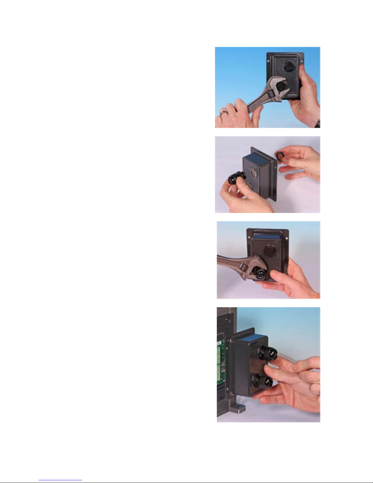
For convenience of wiring more than 8 conductors per cable may be awkward to handle.
1. Use a suitable 21mm spanner to unscrew the
sealing plugs.
2. Screw in the supplied ½” NPT cable glands
complete with new sealing washers in place
of the plug, ensuring that the retaining nut is
properly seated.
3. Tighten the gland to 2.5Nm using a suitable
21mm spanner, to ensure a seal. If a different
gland is used, it must be watertight to IP66.
3. Loosen the gland cap (do not remove it) and
pass the cable in through the gland. When it
has passed through the gland, continue to
push the cable through.
4. Pull through sufficient cable to reach the
connectors required, leaving a little slack.
5. Strip the outer sheath as necessary and
remove 5mm of insulation from the
conductors. No tinning or ferrule is required.
Note:If very stiff or large-diameter cable is
used, it may be convenient to strip the outer
sheath before passing the cable’s conductors
through the gland. However, to ensure a
watertight seal, the cable must have an
undamaged sheath within the gland when it is
tightened.
m-qdos-en-02 32
Page 33

6. Prepare the cable screen(s) by twisting a
suitable length. The twisted length(s) shall
ideally be sleeved to prevent shorting.
7. Secure the end of the cable screen to the
Faston receptacles on the spade connectors
provided.
8. Push the bared conductor into the square hole
in the connector. When the conductor is fully
inserted, tighten the retaining screw to secure
it in place.
Ensure that multi strand
wires are terminated with a
crimp, suitable for the wire
diameter. Failure to do so
may result in electric shock.
9. When all conductors are in position replace
the module cover.
10. Using a 21mm spanner tighten the gland cap
to 2.5Nm to ensure a watertight seal.
Alternatively, tighten the gland by hand until
it is finger-tight and use a spanner to tighten
it further by one-half a turn.
Ensure that unused
openings on the module are
sealed using the blanking
plugs provided. Failure to do
so will result in loss of
ingress protection.
m-qdos-en-02 33
Page 34

11.3 24Vrelay module pcb connectors
As you look at the module the pcb will appear in the same orientation as shown in the
diagram below.
J1 J2 J3 J4 J5
4-20mA 4-20mA Stop/ RLY2 RLY1
O/P GND I/P GND +24V Contact N/O C N/C N/O C N/C
J6 J7
1 1 1 1 12 2 2 3 3
Never apply mains power to the 4-20mA input, 4-20mA
output,+24VDC or stop contact terminals. Apply the correct signals to
the terminals shown below. Limit signals to the maximum values
shown. Do not apply voltage across other terminals. Permanent
damage, not covered by warranty, may result. The maximum load on
the relay contacts of this pump is 110VAC 5A or 30VDC 5A.
Alarm output (J5)
Connect the output device to the C (common) terminal
of the relay connector and either the N/C (normally
closed) or N/O (normally open) terminal as required.
This relay coil is energised when the pump has an alarm
condition.
Note: Alarm conditions are generated by system errors.
This alarm will not be operated for analogue signal
errors.
The default for Relay 1 is Alarm, on universal+ models
this output (1) can be configured in the control settings
menu.
RLY1
N/C 3
J5
C
N/O
2
1
m-qdos-en-02 34
Page 35

Run status output (J4)
Connect the output device to the C (common) terminal
of the relay connector and either the N/C (normally
closed) or N/O (normally open) terminal as required.
This relay coil is energised when the pump is running.
The default for Relay 2 is run status, on universal+
models this output (2) can be configured in the control
settings menu.
RLY 2
N/C
3
J4
C
N/O
2
1
Configurable remote stop or contact
input - J3
If Analog 4-20mA mode is selected then
terminal J3 will be configured as a remote stop
automatically.
If Contact mode is selected then the input J3
will be configured as a contact input
automatically.
Rem Stop
Stop/contact 2
J3
J2
+24V
GND
1
2
Remote Stop
Connect a remote switch between the Stop/Contact terminal and the +24V terminal of
the Run/Stop I/P connector (J3). Alternatively a 24V logic input may be applied to the
Stop/Contact terminal, ground to the GND terminal of the adjacent 4-20mA I/P connector
(J2).
The sense of the remote stop input can be configured in software using the control settings
menu.
Remote stop is operational in manual and analog mode.
Contact
To operate the pump in contact mode the remote stop input should be set to "High".
Speed: analog input (J2)
The analog process signal must be applied to the I/P
terminal of the Analog connector (J2). Ground to the
GND connector of the same terminal. In Analog mode
the pump set speed will be proportional or inversely
proportional to the analog input.
4-20mA circuit impedance: 250Ω.
Max current 40mA
Note: inverting the signal response is set up in
software. Do not invert the polarity of the terminals.
Analog
GND 2
J2
I/P 1
See also "Analog 4-20mA mode (Universal and Universal+ only)" on page67 and "Calibrate
the pump for 4-20mA control (Universal+ only)" on page72.
m-qdos-en-02 35
Page 36

Speed: analogue output (J1) (Universal+ only)
A current analogue signal within the range 4-20mA is
available between the O/P (output) terminal and the
GND terminal. The current is fixed and directly
proportional to the pump speed. 20mA = maximum
speed, 4mA = zero speed.
There is also an option to match the scale of the 420mA input if this has been reconfigured by the user.
This option is available in the C ontrol settings menu.
Note: If the mA output is to be used for reading from a
multimeter (set on mA), a 250Ω resistor is required in
series.
4-20mA
GND 2
J1
O/P 1
Earth shielding terminals
4.8mm spade terminals are supplied for earth shielding of
cables. The input cable and output cable earths can be
connected to either terminal.
Keep 4-20mA and low voltage signals separate from mains power. Use
separate glanded input cables.
m-qdos-en-02 36
Page 37

11.4 110V relay module pcb connectors
As you look at the module the pcb will appear in the same orientation as shown in the
diagram below.
J1 J2 J3 J4 J5
4-20mA 4-20mA Run Stop RLY2 RLY1
O/P GND I/P GND AC1 AC2 N/O C N/C N/O C N/C
1 1 1 1 12 2 2
J6 J7
3 3
Apply the correct signals to the terminals shown below. Limit signals
to the maximum values shown. Do not apply voltage across other
terminals. Permanent damage, not covered by warranty, may result.
The maximum load on the relay contacts of this pump is 115VAC; max
current 5A. Voltages do not require transformer isolation. The relays
are specified to switch 115VAC mains powered loads. These relay
outputs are not suitable for 24VDC logic signals.
Alarm output (J5)
Connect the output device to the C (common) terminal
of the relay connector and either the N/C (normally
closed) or N/O (normally open) terminal as required.
This relay coil is energised when the pump has an alarm
condition.
Note: Alarm conditions are generated by system errors.
This alarm will not be operated for analogue signal
errors.
The default for Relay 1 is Alarm, on universal+ models
this output (1) can be configured in the control settings
menu.
RLY1
N/C 3
J5
C
N/O
2
1
m-qdos-en-02 37
Page 38

Run status output (J4)
Connect the output device to the C (common) terminal
of the relay connector and either the N/C (normally
closed) or N/O (normally open) terminal as required.
This relay coil is energised when the pump is running.
The default for Relay 2 is run status, on universal+
models this output (2) can be configured in the control
settings menu.
RLY 2
N/C
3
J4
C
N/O
2
1
Remote stop input (J3)
Apply a signal of 85VAC to 130VAC across terminals AC1
and AC2 to stop the pump. Polarity is not important.
The pump will not run while this signal is applied. In
manual and analog mode, the pump will start when the
signal is removed.
Rem Stop
AC1 2
J3
AC2 1
Speed: analog input (J2)
The analog process signal must be applied to the I/P
terminal of the Analog connector (J2). Ground to the
GND connector of the same terminal. In Analog mode
the pump set speed will be proportional or inversely
proportional to the analog input.
4-20mA circuit impedance: 250Ω.
Max current 40mA
Note: inverting the signal response is set up in
software. Do not invert the polarity of the terminals.
Analog
GND 2
J2
I/P 1
Speed: analogue output (J1) (Universal+ only)
A current analogue signal within the range 4-20mA is
available between the O/P (output) terminal and the
GND terminal. The current is fixed and directly
proportional to the pump speed. 20mA = maximum
speed, 4mA = zero speed.
There is also an option to match the scale of the 420mA input if this has been reconfigured by the user.
This option is available in the C ontrol settings menu.
Note: If the mA output is to be used for reading from a
multimeter (set on mA), a 250Ω resistor is required in
series.
4-20mA
GND 2
J1
O/P 1
m-qdos-en-02 38
Page 39

Earth shielding terminals
4.8mm spade terminals are supplied for earth shielding of cables.
The input cable and output cable earths can be connected to
either terminal.
4-20mA and low voltage signals separate
from mains power. Use separate glanded
input cables
m-qdos-en-02 39
Page 40

12 PROFIBUS control wiring
Interfacing the pump with the PROFIBUS network is by means of an M12 connector mounted
on a flying lead on the front of the pump.
It is the user’s responsibility to ensure the safe and reliable operation of the pump under
PROFIBUS control.
Note: The transmission speed is limited to a maximum of 1.5Mbit/s.
12.1 PROFIBUS installation
All dev ices in the bus system must be connected in a line. An IP66 rated T adaptor should
be used to connect the pump to the PROFIBUS line. A maximum of 32 stations (to include
master, slaves and repeaters) are possible and both the beginning and the end of the cable
must be terminated with a terminating resistor.
The M12 socket provided for PROFIBUS installation is IP66 rated. To maintain an IP66 rated
system, the PROFIBUS cable, T adaptors and terminating resistors used must be fitted with
IP66 rated M12 industrial connectors.
Note: To prevent low- frequency ground loops, screening which is earthed at one end
should be used. To counter magnetic HF pick-up, shielding earthed at both ends as well as
twisted conductors should be used, this will have no effect against electrical HF pick -up.
The permissible overall length of the bus cabling will vary according to the required bit
rate. If a longer cable or higher bit rate are required repeaters should be used. The
maximum bit rates achievable are shown in the table below.
Bit rate (Kbit/s) Max. length of type A bus cable (m)
1500 200
500 400
187.5 1000
93.75 1200
19.2 1200
9.6 1200
Note: Total stub length should not exceed 6.6m.
m-qdos-en-02 40
Page 41

12.2 Pin assignments at the pump
Pin 4
Pin 3
Pin 5
Pin 1
Pin 2
Pin No. Signal Function
1 VP +5V supply for terminating resistors
2 RxD/TxD-N Data line minus (A-line)
3 DGND Data ground
4 RxD/TxD-P Data line plus (B-line)
5 Shield Ground connection
Note: If the pump is the last bus device connected to the PROFIBUS cable it must be
terminated using terminating resistor (PROFIBUS standard EN 50170). To maintain ingress
protection the resistor must be IP66 rated.
m-qdos-en-02 41
Page 42
13 Switching on (Manual, PROFIBUS, Universal and
Universal+)
13.1 Switching on the pump for the first time (Manual,
PROFIBUS, Universal and Universal+ only)
Power-up the pump.
The pump displays the start- up screen with the Watson- Marlow Pumps logo for three
seconds.
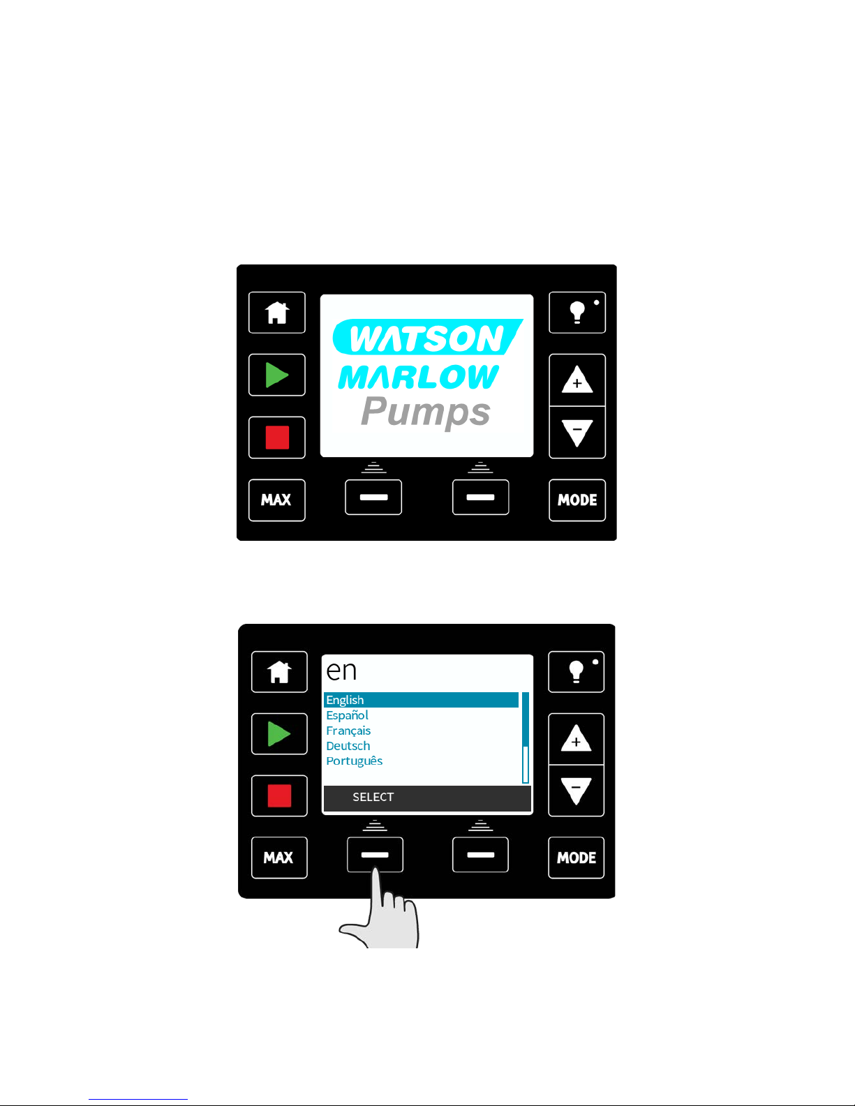
Selecting your chosen display language
Use the +/- keys to move the selection bar to your required language. Press SELECT to
choose.
Your selected language will now be displayed on screen, choose CONFIRM to continue. All
displayed text will now appear in your chosen language.
m-qdos-en-02 42
Page 43

Choose REJECT to return to the language choice screen.
The pump is preset with operational parameters as shown in the table below:
First-time start-up defaults
Flow rate
qdos120:960ml/min
qdos60:480ml/min
qdos30:240ml/min
qdos20:120ml/min
Pump status Stopped
Calibration
qdos120:16 ml/rev
qdos60:6.67ml/rev
qdos30:8 ml/rev
qdos20:4 ml/rev
Flow unit ml/min
Backlight 30 minutes Pump tag WATSON-MARLOW
Auto restart Off
This then proceeds to the home screen.
m-qdos-en-02 43
Page 44

The pump is now ready to operate according to the defaults listed above.
Note: The display background colour changes according to running state as follows:
l White background indicates pump stopped
l Blue background indicates pump running
l Red background indicates error or alarm
All operating parameters may be changed by means of key-presses (see "Pump operation"
on page46).
13.2 Switching the pump on in subsequent power cycles
(Manual, PROFIBUS, Universal and Universal+ only)
Subsequent power-up sequences will jump from the start-up screen to the home screen.
l The pump runs a power- on test to confirm proper functioning of the memory and
hardware. If a fault is found, an error code is displayed (see "Error codes" on page108).
l The pump displays the start-up screen with the Watson-Marlow Pumps logo for three
seconds followed by the home screen.
l Start-up defaults are those in place when the pump was switched off last.
Check that the pump is set to operate as you require it.
The pump is now ready to operate.
All operating parameters may be changed by means of key-presses (see "Pump operation"
on page46).
Power interruption
This pump has an auto restart feature which, when active, will restore the pump to the
operating state it was in when power was lost. See "Main menu (Manual, PROFIBUS,
Universal and Universal+ only) " on page84.
Stop / start power cycles
Do not power up/power down for more than 20 starts per hour, whether manually or by
means of the auto restart facility. We recommend remote control where a high frequency of
power cycles is required.
m-qdos-en-02 44
Page 45

14 Switching on (Remote)
When power is supplied to the pump, all the LED icons will illuminate for three seconds.
After this period the pump will operate in accordance with the inputs received.
m-qdos-en-02 45
Page 46

15 Pump operation
Note: Sections "Keypad functions (Manual, PROFIBUS, Universal and Universal+ only)"
below up to and including "Help (Manual, PROFIBUS, Universal and Universal+ only)" on
page105 apply to Manual, PROFIBUS, Universal and Universal+ only. It is only possible to
control the Remote pump via the input and output, (I/O) provided.
15.1 Pump operation (Remote pump)
The remote pump will operate proportionally to the analog signal provided. The default
figures are 4.1mA = 0 rpm, 19.8mA = 125 rpm.
To stop the pump remotely apply a signal, minimum 5V, maximum 24V, to input pin 1. To
run the pump in reverse, apply a signal, minimum 5V, maximum 24V to input pin 5.
15.2 Pump operation (Manual, PROFIBUS, Universal and
Universal+ only)
Keypad functions (Manual, PROFIBUS, Universal and Universal+ only)
Backlight
Change value /
move selection
bar
Mode
Priming
Stop
Start
Home
Colour TFT display
Left hand
function
Right hand
function
HOME
When the HOME key is pressed it will return the user to the last known operating mode. If
modifying pump settings when the HOME key is pressed, it will disregard any setting
changes and return you to the last known operating mode.
START
This key will start the pump at the displayed set speed when in manual mode or flow
calibration. This key will deliver a contact dose volume when in CONTACT mode. It has no
effect in the other remote modes.
STOP
This key will stop the pump when pressed at any time.
m-qdos-en-02 46
Page 47

MAX
This key can be used to prime the pump when in manual mode. When pressed the pump
will operate at maximum flow rate.
FUNCTION KEYS
When pressed will perform the function displayed on the screen directly above the relevant
function key.
After 30 minutes of no keypad activity, the HMI display will dim to 50% brightness.
To restore full power to the display and reset the timer, press the BACKLIGHT key.
+/- KEYS
These keys are used to change programmable values within the pump. For example, flow
rate. These keys are also used to move the selection bar up and down in the menus.
MODE
To change modes or mode settings, press the MODE key. The MODE key can be pressed at
any time to enter the mode menu. If modifying pump settings when the MODE key is
pressed, it will disregard any setting changes and return you to the MODE menu.
SCREEN SAVER
The display refreshes every 60 seconds. When this occurs you may notice a brief flash.
Screen Icons (Manual, PROFIBUS, Universal and Universal+ only)
Under certain conditions, various icons will appear in the screen display area:
The pump displays a RED stop icon when it is in a manually stopped condition.
In this state the pump will not start unless the START key is pressed.
The pump displays a RED PAUSE icon when it is receiving a remote stop input
whilst in a standby condition. The pump is placed in a standby condition by
pressing the START key in manual mode, or by selecting Analogue mode.
In this state the pump will respond to a change in state of the start/stop input,
and may start automatically when a control signal is received.
When the pump is running it displays a turning icon to indicate a pumping state.
Fundamental work with regard to lifting, transportation, installation,
starting-up, maintenance and repair should be performed by qualified
personnel only. The unit must be isolated from mains power while
work is being carried out. The motor must be secured against
accidental start-up.
m-qdos-en-02 47
Page 48

Switching between modes (Manual, PROFIBUS, Universal and Universal+ only)
Note: Remote model does not feature selectable modes.
Using +/- keys will scroll through the available modes. The available modes are:
l Manual (default)
l Flow calibration
l Analog 4–20mA (Universal and Universal+ only)
l Contact mode (Univ ersal+ only)
l PROFIBUS (PROFIBUS only)
l Fluid recovery
l CANCEL
Use SELECT to choose mode. Use the right hand function key to alter mode settings.
m-qdos-en-02 48
Page 49

16 Manual mode (Manual, PROFIBUS, Universal and
Universal+ only)
All settings and functions of the pump in manual mode are set and controlled by means of
key-presses. Immediately after the start-up display sequence (detailed in: "Switching the
pump on in subsequent power cycles (Manual, PROFIBUS, Universal and Univ ersal+ only)"
on page44 ), the manual mode home screen will be displayed unless auto restart is
enabled.
If enabled, the pump will return to the last known operating state when the power was
lost. When the pump is running it displays an animated clockwise arrow. In normal
operation, the direction of flow is into the bottom port of the pumphead and out of the top
port.
If an exclamation mark (! ) is displayed, it indicates that Auto restart is on (see 18.3
General settings on page 57). If a padlock icon shows, it indicates that the keypad lock is
on.
START
Starts the pump at the current flow displayed, and the display background changes to blue.
If the pump is running pressing this has no effect.
m-qdos-en-02 49
Page 50

STOP
Stops the pump. The display background changes to white. If the pump is not running
pressing this has no effect.
INCREASING AND DECREASING FLOWRATE
Using the +/- keys will increase or decrease the flowrate.
Decreasing flowrate:
l A single key press will decrease flowrate by the least significant digit of the chosen
flowrate unit.
l Repeat key presses as required to achieve the desired flowrate.
l Hold down the key for flowrate scrolling.
m-qdos-en-02 50
Page 51

Increasing flow rate:
l A single key press will increase flowrate by the least significant digit of the chosen
flowrate unit.
l Repeat key -presses as required to achieve the desired flowrate.
l Hold down the key for flowrate scrolling.
Max 100% function (Manual mode only)
l Press and hold the MAX key to run at maximum flow.
l Release the key to stop the pump.
l The volume dispensed and time elapsed are displayed whilst the MAX key is pressed
and held. The MAX function will work when the key is pressed in manual mode
regardless of the status of the START/STOP input.
m-qdos-en-02 51
Page 52
17 PROFIBUS mode(PROFIBUS only)
In this operating mode PROFIBUS control can be enabled or disabled. The qdos PROFIBUS
pump is designed so that the station address can only be set from the pump. The user can
set the station address within this mode.
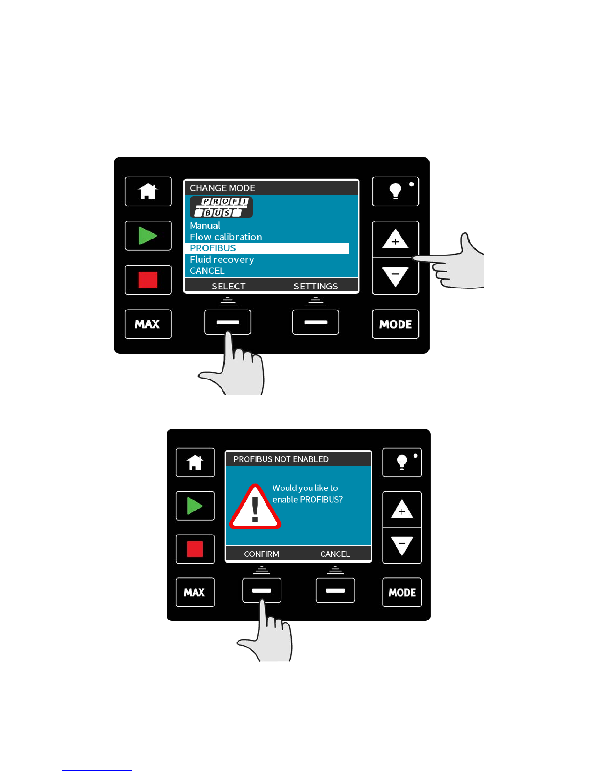
Select MODE
Using the +/- keys scroll to PROFIBUS and press SELECT
If PROFIBUS is not enabled, the screen below will prompt you to CONFIRM that you would
like to enable PROFIBUS.
On the PROFIBUS home screen the white P icon indicates that there is data exchange.
m-qdos-en-02 52
Page 53

Pressing the INFO function key will display further information.
17.1 Assigning the PROFIBUS station address at the pump
The station address can only be set from PROFIBUS settings. The station address cannot be
automatically assigned by the master.
Select MODE
Using the +/- keys scroll to PROFIBUS and press SETTINGS
m-qdos-en-02 53
Page 54

Using the +/- k eys alter the station address, in the range from 1 to 125. (126 is the default
station address).
Press FINISH to set the station address, or NEXT to enable/disable PROFIBUS
communication.
Use the +/- key s to enable or disable PROFIBUS communication and press FINISH.
m-qdos-en-02 54
Page 55

17.2 PROFIBUS communication errors
In PROFIBUS mode, the screen below is displayed, the P indicates data exchange is
happening.
This screen will only be displayed after successful implementation of Master Slave
communications, which always follow the sequence described below.
Power ON Reset
Power ON / reset of Master or Slave
Download of parameters into the eld device (selected
during conguration by the user)
Download of I/O conguration into the eld device
(selected during conguration by the user)
Cyclic data exchange (I/O data) and eld device reports
diagnostic
Parameterisation
I/O conguration
Data exchange
If data exchange is lost at any time, the following screen will be displayed. The first red dot
corresponds to the stage at which the error occurred and subsequent stages will indicate a
red dot because the communication sequence halted before this point.
m-qdos-en-02 55
Page 56

The screen will state running or stopped, depending on how the user has set up the failsafe function within the PROFIBUS GSD file (see "PROFIBUS GSD file" below ). The MODE
button gives access to the PROFIBUS settings and the station address. When the menus are
accessed, the pump is still in PROFIBUS bus mode but with no communications.
After five minutes of inactivity the pump will revert back to the home screen and discard
any unsaved changes, if there are still no communications then the BUS ERROR screen will
be displayed.
17.3 PROFIBUS GSD file
The qdos PROFIBUS pump can be integrated into a PROFIBUS DP V0 network using a
General Station Data (GSD) file. The file identifies the pump and contains key data
including its communication settings, the commands it can receive and the diagnostic
information it can pass to the PROFIBUS master on interrogation.
The GSD file— file name WAMA0E7D.GSD—can bedownloaded from the Watson- Marlow
website and installed; or typed into a PROFIBUS master directly from this manual using a
GSD editor program.
Note: The data- flow to and from the pump may need to be byte- reversed, due to
differences of handling the data between suppliers of master devices.
The GSD file, filename: WAMA0E7D.GSD
;
;*************************************************************************
***********
;*
=======================================================
========================= *
;* *
;* Watson-Marlow Bredel Pumps *
;* Bickland Water Road *
;* Falmouth *
;* Cornwall *
;* TR11 4RU *
;* Tel.: +44(1326)370370 *
;* FAX.: +44(1326)376009 *
m-qdos-en-02 56
Page 57

;* *
;*
=======================================================
========================= *
;* Filename: WAMA0E7D.GSD *
;* GSD file version 3 from 2013-09-24 *
;* -------------------------------------------------------------------------------- *
;* *
;*************************************************************************
***********
#Profibus_DP
GSD_Revision = 3
Vendor_Name = “Watson Marlow”
Model_Name = “Qdos Profibus Pump”
Revision = “Version 3.00”
Ident_Number = 0x0E7D
Protocol_Ident = 0
Station_Type = 0
FMS_supp = 0
Hardware_Release = “V1.00”
Software_Release = “V1.00”
Redundancy = 0
Repeater_Ctrl_Sig = 0
24V_Pins = 0
9.6_supp = 1
19.2_supp = 1
45.45_supp = 1
93.75_supp = 1
187.5_supp = 1
500_supp = 1
1.5M_supp = 1
3M_supp = 1
6M_supp = 1
12M_supp = 1
MaxTsdr_9.6=60
MaxTsdr_19.2=60
MaxTsdr_45.45=60
MaxTsdr_93.75=60
MaxTsdr_187.5=60
MaxTsdr_500=100
m-qdos-en-02 57
Page 58

MaxTsdr_1.5M=150
MaxTsdr_3M=250
MaxTsdr_6M=450
MaxTsdr_12M=800
Slave_Family = 0
Implementation_Type = “VPC3+S”
Info_Text=”PROFICHIP: PROFIBUS DPV0 - slave, Watson Marlow Qdos”
Bitmap_Device = “WAMA_1N”
Freeze_Mode_supp=1
Sync_Mode_supp=1
Fail_Safe=1
Auto_Baud_supp=1
Set_Slave_Add_supp=0
Min_Slave_Intervall=6
Modular_Station=0
Max_Diag_Data_Len=34
Max_User_Prm_Data_Len = 9
Ext_User_Prm_Data_Const(0)= 0x00,0x00,0x00,0x00,0x00,0x00,0x00,0x00,0x00
Module=”WM Pump, 3/14 word out/in” 0x62,0x5D
1
EndModule
17.4 User Parameter Data
The user parameter data is set by entering values into the ‘Ext_User_Prm_Data_ Const(0)’
line of the GSD file. This is indicated below and the relevant bytes are listed in the table.
No further changes should be made to the GSD file and Watson- Marlow accepts no
responsibility for pump failures arising from changes to the GSD file.
Byte1Byte2Byte3Byte4Byte5Byte6Byte7Byte8Byte
9
8 bit Byte 1 Pre Assigned
8 bit Byte 2 Reserved
8 bit Byte 3 Min Speed (High byte of 16-bit unsigned)
8 bit Byte 4 Min Speed (Low byte of 16-bit unsigned)
8 bit Byte 5 Max Speed (High byte of 16-bit unsigned)
8 bit Byte 6 Max Speed (Low byte of 16-bit unsigned)
m-qdos-en-02 58
Page 59

8 bit Byte 7 Fail Safe
8 bit Byte 8 Fail Safe Speed (Low byte of 16-bit unsigned)
8 bit Byte 9 Fail Safe Speed (High byte of 16-bit unsigned)
Set Min/Max Speeds
The Min/Max Speed parameters are used to set the minimum and max imum speed from the
PROFIBUS interface. The values are only used if the matching bit in the Control Word is
enabled and they are not zero. The values are 16 bit unsigned in 1/10th of RPM of the head
speed.
If the user requests the pump to operate at a lower speed than the defined minimum speed
from the user parameter data (bytes 3, 4) then the pump will operate at the defined
minimum speed.
If a max imum speed has been configured in the user parameter data, then the pump will be
limited to this maximum speed even when the master requests a higher rpm.
Fail Safe
The fail-safe user parameter is used to set the correct course of action to take in the event
of a PROFIBUS communications failure. The fail-safe byte is configured as shown in the
following table. If no bits are set or an invalid bit pattern is set the default fail safe
behaviour shall be to stop the pump.
Hex Description
0x00 The pump will stop
0x01 Continue driving using the last demanded speed
0x02 Continue driving using the fail safe speed
0x03 - 0x07 R eserved
Fail Safe Speed
The fail-safe speed parameter is used to set the speed at which the pump should be driven
if a PROFIBUS communications error occurs and if the fail-safe user parameter is set to
0x02.
17.5 PROFIBUS data exchange
The data in this section is provided as reference material for a PROFIBUS network operator.
Operating this pump under PROFIBUS control is beyond the scope of this instruction
manual. Consult your PROFIBUS network literature for further information.
Default address 126
PROFIBUS Ident 0x0E7D
GSD File: WAMA0E7D.GSD
Config: 0x62, 0x5D (3 words out, 14 words in)
User parameter bytes: 6
Cyclic Data Write (from Master to pump)
Cyclic Data Write (from Master to pump)
16 bit Byte 1 (low) , 2 (high) Control Word
16 bit Byte 3 (low) , 4 (high) Pumphead Speed Setpoint (unsigned)
m-qdos-en-02 59
Page 60

Cyclic Data Write (from Master to pump)
16 bit Byte 5 (low) , 6 (high) Set Flow Calibration in μl per revolution
Control Word
Bit Descrip tion
0 Motor running (1= Running)
1 Direction ( 0= CW, 1= CCW)
2 Motor revolution counter reset (1=R eset count)
3 Reserved
4 Enable User Parameter Min/Max Speeds (1= Enabled)
5 Enable Fieldbus master to set Flow Calibration (1= Enabled)
6 Ignore leak detection sensor
7 Fluid Level Reset
8-15 Reserved
Pumphead Speed Setpoint
The speed setpoint is a 16-bit unsigned integer value that represents the speed of the
pump head in 1/10th of RPM. For example 1205 represents 120.5 RPM.
Set Flow Calibration
This parameter is used to set the flow calibration value from the fieldbus interface. The
value is a 16 bit unsigned integer representing μl per revolution of the pumphead. Note
that this value is only used if bit 5 of the Control Word is enabled.
Ignore Leak Detection Sensor
If bit 6 of the control word is enabled, the following run screen will be displayed.
m-qdos-en-02 60
Page 61

If a leak is detected the leak detect screen (16.1 Leak detection on page 54) will not be
displayed. Bit 10 of the status word will be activated to indicate that a leak has occurred
and the pump will continue to run until the Master indicates what action should be taken.
Cyclic Data Read (from pump to Master)
Cyclic data read (from p ump to Master)
16 bit Byte 1, 2 Status Word
16 bit Byte 3, 4 Pumphead Measured Speed (unsigned)
16 bit Byte 5, 6 Hours Run
16 bit Byte 10,9 No of full motor revolutions
16 bit Bytes 8,7 Reserved
32 bit Byte 13, 14, 15, 16 Fluid Level
32 bit Byte 17, 18, 19, 20 Unassigned
32 bit Byte 21, 22, 23, 24 Unassigned
32 bit Byte 25, 26, 27, 28 Unassigned
Status Word
Bit Description
0 Motor running (1= Running)
1 Global Error Flag (1= Error)
2 Fieldbus C ontrol (1= Enabled)
3 Reserved
4 Over current error
5 Under voltage error
6 Over voltage error
7 Over temperature error
8 Motor stalled
9 Tacho fault
10 Leak detected
11 Low Setpoint- Out of range
12 High Setpoint- Out of range
13 Fluid level alert
14 Reserved
15 Reserved
m-qdos-en-02 61
Page 62

Pumphead Speed
The pumphead speed is a 16-bit unsigned integer value that represents the speed of the
pump head in 1/10th of RPM. For example 1205 represents 120.5 RPM.
Hours Run
The hours run parameter is a 16 bit unsigned integer and will represent whole hours of
runtime.
No of full motor revolutions
This counts down from FF for each complete motor revolution. Reset this counter to FF by
using bit 2 of the control word. The motor relates to the motor inside the pump before the
gearbox ratio. The number of pumphead revolutions can be obtained by dividing the
number of motor revolutions by the gearbox ratio of 29.55.
BYTE HEX TO DECIMAL
10 9 10 9
A FF FF 65536
B FF C4 65476
MOTOR FULL
REVOLUTIONS
A Minus B 59
A = Start of Dose
B = End of Dose
PUMPHEAD REVOLUTIONS
MOTOR REVS GEARBOX RATIO
59 29.55
Divide
1.996 RPM
Read Flow Calibration
The value is a 16 bit unsigned integer representing μl per revolution.
17.6 Device-related diagnostic data
8 bit Byte 1 Header Byte
16 bit Byte 2, 3 Reserved
16 bit Byte 4, 5 Reserved
16 bit Byte 6, 7 Min Speed (unsigned)
16 bit Byte 8, 9 Max Speed (unsigned)
32 bit Byte 10, 11, 12, 13 Software Version Main CPU
32 bit Byte 14, 15, 16, 17 Software Version HMI CPU
32 bit Byte 18, 19, 20, 21 Software Version Flash
32 bit Byte 22, 23, 24, 25 Software version PROFIBUS CPU
17.7 Channel-related diagnostic data
Channel-related diagnostic blocks are always three bytes long in the following format:
m-qdos-en-02 62
Page 63

Byte 26 Header
Byte 27 Channel type
Byte 28 Channel-related error code
Channel-related diagnostic data Byte 3
Global error =0xA9 (General error)
Over current =0xA1 (Short circuit)
Under voltage =0xA2 (Under voltage)
Over voltage =0xA3 (Over voltage) =0xA3 (Over voltage)
Motor stall =0xA4 (Overload)
Over temp =0xA5 (Over temp) =0xA5 (Over temp)
Tacho fault =0xB1 (Device related 0x11)
Leak detected =0xB2 (Device related 0x12)
Fluid lev el alert =0xB3 (Device related 0x15)
Reserved =0xA6 (Reserved)
Setpoint out of range- high =0xA7 (Upper limit exceeded)
Setpoint out of range- low =0xA8 (Lower limit exceeded)
m-qdos-en-02 63
Page 64

18 Flow calibration mode (Manual, PROFIBUS,
Universal and Universal+ only)
This pump displays flow rate in ml/min.
Setting the flow calibration
Select MODE
Using the +/- keys, scroll to Flow calibration and press SELECT.
Using the +/- keys enter the maximum flow rate limit and press ENTER.
m-qdos-en-02 64
Page 65

Press START to begin pumping a volume of fluid for calibration.
Press STOP to stop pumping fluid for the calibration.
m-qdos-en-02 65
Page 66

Using the +/- keys enter the actual volume of fluid pumped.
To accept the new calibration press ACCEPT or RECALIBRATE to repeat the procedure.
Press HOME or MODE to abort.
The pump is now calibrated.
m-qdos-en-02 66
Page 67

19 Analog 4-20mA mode (Universal and Universal+
only)
In this remote operating mode the flowrate will be proportional to the external milliamp
signal input received by the pump. The Universal pump will operate at 0 rpm when 4.1mA
is received and maximum rpm when 19.8mA is received.
In the Univ ersal+ pump the relationship between the external milliamp signal and the flow
rate is determined by configuring the two points A and B as shown in the graph below. The
rate of flow can be proportional or inversely proportional to the analogue milliamp input.
The default values stored in the pump are:
A—4.1mA, 0 rpm
B (qdos20)—19.8mA, 55 rpm
B (qdos30,qdos60 and qdos120)—19.8mA, 125 rpm
Flowrate
mA
A
B
When the mA signal received is greater than the level defined by point A, the run status
output will be energised as the pump is running.
m-qdos-en-02 67
Page 68

To select Analog 4-20mA mode:
l Select MODE.
l Using the +/- keys, scroll to Analog 4-20mA and press SELECT.
The current signal being received by the pump is displayed, for information only, on the
HOME screen.
Pressing the INFO function key will display further information.
m-qdos-en-02 68
Page 69

Press the INFO key again to display the 4-20mA calibration figures.
Analog Scaling Factor
The Scaling Factor is a method of adjusting the 4-20mA profile by using a multiplication
factor.
Press +/- from the HOME screen to access the scaling factor.
Use the +/- keys to enter a multiplication factor. A figure of 1.00 will not alter the 4-20mA
profile. A figure of 2 will double the flow rate output from a specific mA signal. A figure of
0.5 will halve the output.
m-qdos-en-02 69
Page 70

Press SELECT once you have chosen the required factor.
Press ACCEPT to confirm the new 4-20mA PROFILE figures. This will not alter the stored A
and B points, the multiplication factor will re- scale the 4- 20mA profile. To re- set the
original flow rates re-set the multiplication factor to 1.00.
m-qdos-en-02 70
Page 71

original 4-20mA Prole
scaling factor of 0.5
scaling factor of 1.5
mA
owrate %
The 4-20mA profile is a linear relationship where y=mx+c the scaling factor alters the
gradient m. The speed limit function in control settings will also scale the analog signal.
The difference between scaling factor and speed limit is that the speed limit is a global
variable applied in all modes. The speed limit cannot exceed the high flow rate set point
(B).
The speed limit function takes precedence over the scaling factor. For example if the
qdos20 4-20mA profile is 0% flow at 4mA to 100% flow at 20mA and a speed limit of 33 rpm
is applied, followed by a scaling factor of 0.5, then the output will be 30%. If a scaling
factor of 2 is applied in the same scenario then the output will be 33 rpm or 60%, as the
speed limit takes precedence over the scaling factor.
If you are using manual scaling it is recommended to not use speed limit to avoid
confusion.
m-qdos-en-02 71
Page 72

19.1 Calibrate the pump for 4-20mA control (Universal+ only)
This feature is only available in the Univ ersal+ model.
The pump must be stopped before attempting to calibrate the 4-20mA values. High and low
signals must be within range. If the signal sent is out of range you will not be able to set
the signal input value and progress to the next step in the process.
Select MODE.
Using the +/- keys scroll to Analog 4-20mA and press CALIBRATE 4-20mA.
Choose whether to enter the current values manually via the keypad, or whether to apply
the current signals electrically to the analog input.
m-qdos-en-02 72
Page 73

Setting a high signal
Send the high signal input to the pump, or enter the current value using the +/- keys.
ACCEPT appears when high mA signal is within tolerance limits. Press ACCEPT to accept
the high signal input or CANCEL to return to the previous screen.
m-qdos-en-02 73
Page 74

Setting high flow calibration
Using the +/- keys scroll to the desired flow rate. Select SET FLOW or press BACK to
return to the previous screen.
Setting a low signal
Send the low signal input to the pump, or enter the current value using the +/- keys.
m-qdos-en-02 74
Page 75

If the range between the low and high signal is less than 1.5mA, the following error
message will be displayed.
ACCEPT appears when low mA signal is within tolerance limits. Press ACCEPT to accept the
low signal input or CANCEL to return to the previous screen.
m-qdos-en-02 75
Page 76

Setting low flow calibration
Using the +/- keys scroll to the desired flow rate. Select SET FLOW.
This proceeds to the screen confirming calibration is complete. Select CONTINUE to start
in proportional mode or MANUAL to continue in manual mode.
m-qdos-en-02 76
Page 77

20 Contact Mode (All Universal and Universal+ models
except 110V relay versions)
In this operating mode the pump will meter a specific dose of fluid when an external pulse
is received.
The dose volume is a user defined value between 0.1ml and 999l.
20.1 Contact settings
To setup contact mode, firstly you will need to define the settings. To do this, press the
MODE key, move the selection bar to Contact and select SETTINGS with the right-hand
function key.
This will display the settings.
m-qdos-en-02 77
Page 78

Use NEXT to move the selection bar to the next setting.
Use +/- to alter the value of the highlighted setting:
l The contact dose is the volume of fluid the pump will dispense when an external pulse
is received on input pin 2.
l The flow rate will determine the time taken to complete each dose.
l Contact memory determines what the pump will do when pulses are received while a
dose is in progress. If set to “ignore” the pulses will be forgotten by the pump. If set to
“add” any pulses received while dosing will be queued up in memory and will be
dispensed when the current dose has finished.
If pulses are buffered in the memory then the pump will not stop between doses.
Once you have decided all your settings press FINISH and press SAVE to store.
Electrical pulse specification
t=40ms (min) to 1000mS (max)
Vmin > 1.9V
Time (t)
t
Vmax
V
0
m-qdos-en-02 78
Page 79

20.2 Contact operating mode (All Universal and Universal+
models except 110V relay versions)
To enter contact mode press the MODE key, move the selection bar to Contact, and press
SELECT.
The contact mode home screen will be displayed. The home screen displays the contact
dose, the flow rate, and the dose time remaining when a dose is in progress. The dose time
is only displayed on screen when it is between 3 seconds and 999 seconds.
When the pump is not dosing it is possible to manually start a dose by pressing the START
key.
Doses which operate for less than 3 seconds are not recommended.
m-qdos-en-02 79
Page 80

Pulse dosing as an operation mode has its limitations. From an application perspective it is
often not the most efficient method of achieving concentration consistency due to the
pump only metering when a pulse is received, as opposed to continuously running in
proportion to the flow. Intermittently dosing into a fluid line will require enough pipe to
ensure the solution is adequately mixed, or a mixing tank.
With the ability to operate at very low speeds, metering chemicals is a much better
solution than dosing them at intervals. We recommend examining your process to identify
whether a 4-20mA signal can be used rather than a pulse. Where technology does not allow
a 4-20mA signal we recommend using a signal converter accessory. This can be used to
change your pulse signal to a 4-20mA signal, ideal for metering (see "Analog 4-20mA mode
(Universal and Universal+ only)" on page67).
20.3 Fluid recovery mode (Manual, PROFIBUS, Universal and
Universal+ only)
In this operating mode, the pump can be run in reverse for short periods to recover
fluid/chemicals pumped. This is mainly used for maintenance purposes.
Press the MODE key, using the +/- keys position the selection bar over the fluid recovery
menu option and press SELECT.
m-qdos-en-02 80
Page 81

If the pump is already running then the following screen will be displayed. The pump must
be stopped before it can be reversed to recover fluid. Press STOP PUMP.
An instruction is now displayed. There is a warning to ensure that your system design
permits reverse flow. If unidirectional valves are installed then reverse flow will not
function and the pump will build up excessive pressure within the pipework.
Press and hold RECOVER to start running the pump in reverse and recover fluid. The screen
below will be displayed whilst RECOVER is held down. As fluid is recovered the volume
recovered and time elapsed will increase.
m-qdos-en-02 81
Page 82

Release RECOVER to stop running the pump in reverse.
20.4 Remote fluid recovery (Universal and Universal+ models
without relay modules)
It is possible to run the pump in rev erse and recover fluid automatically in the analog 420mA mode. To achieve this, it is necessary to enable remote fluid recovery functionality.
To enable this position the selection bar over fluid recovery in the mode menu and press
the SETTINGS function key.
Select ENABLE to turn this functionality on. The reverse process can be used to switch the
function off.
When this function is enabled, the pump operation can be reversed in analog 4-20mA mode
by applying minimum 5V to maximum 24V to pin 5 of the pump input. The pump will
operate at a reversed set speed proportional to the 4-20mA input applied to pin 3.
m-qdos-en-02 82
Page 83

This operating method allows for fluid recovery from your delivery line. It should not be
used for bulk fluid transfer.
Once enabled, remote fluid recovery should be operated in the following sequence:
1. Send a remote stop signal (apply 5 - 24 volts to input pin 1).
2. Apply 5 - 24 volt to pin 5 of the pump input.
3. Remove the remote stop signal.
4. Apply 4 - 20mA to the analog input. This will cause the pump to run in reverse at a
speed proportional to the analog signal.
5. Apply remote stop signal when enough fluid has been recovered.
6. Remove the voltage at pin 5 of the pump inputs.
7. Remove the remote stop signal when you are ready to run forwards again.
m-qdos-en-02 83
Page 84

21 Main menu (Manual, PROFIBUS, Universal and
Universal+ only)
To access the main menu press the MENU button from one of the HOME screens or INFO
screens.
For example: Manual HOME screen Manual INFO screen
This will display the main menu as shown below. Use the +/- keys to move the selection
bar between the available options.
Press SELECT to choose an option.
Press EXIT to return to the screen from where the MENU was called.
m-qdos-en-02 84
Page 85

21.1 Fluid level monitor (Manual, PROFIBUS, Universal and
Universal+ only)
The fluid level monitor can be used to estimate the fluid level left in your supply tank.
When activated, the pump will display a bar on the home screen indicating the volume of
fluid in the tank. As the pump meters fluid, the volume of fluid in the supply reservoir will
reduce, the bar will track the reducing volume. The pump can be set up to output an alarm
when a defined level of fluid is reached. This will warn the operator to change the fluid
supply barrel or level to ensure that the pump does not run dry.
When the fluid level is estimated at zero the pump will stop.
On selection of this function from the main menu, it will ask you whether you wish to
ENABLE the fluid level bar.
m-qdos-en-02 85
Page 86

After pressing ENABLE, the pump will display the fluid level setup options.
If you press DISABLE the pump will deactivate the fluid level monitor. The fluid bar will no
longer appear on the HOME screens.
The fluid volume unit can be changed by pressing the US GALLONS or LITRES key, the
key name will change depending upon the unit selected.
To configure the level monitor, select this option from the menu.
m-qdos-en-02 86
Page 87

Enter the maximum level of your reservoir or supply container using the +/- keys to adjust
the volume.
Press NEXT when you are happy you have the correct volume.
Now use the +/- keys to set the alert level. In the screen above the alert level is set to
20%. Press SELECT to return to the fluid level monitor menu.
m-qdos-en-02 87
Page 88

If you need to adjust the v olume of fluid in the tank, for example when re-filling, then press
SELECT when the bar highlights the Adjust level option.
You can now use the +/- keys to adjust the level of fluid in the tank.
The accuracy of the fluid level monitor will improve with regular calibration of the pump.
m-qdos-en-02 88
Page 89

21.2 Security settings (Manual, PROFIBUS, Universal and
Universal+ only)
Security settings can be changed by selecting SECURITY SETTINGS from the Main menu.
Auto keypad lock
Press ENABLE/DISABLE to switch on/off the Auto keypad lock. When active the keypad
will ‘ lock’ after 20 seconds of inactivity.
Once locked it will display the screen below when any key is pressed. To unlock the
keypad press the two unlock keys together.
m-qdos-en-02 89
Page 90

The padlock icon will appear on the operating mode home screen to show that keypad lock
is activated.
Note that the STOP and BACKLIGHT keys will alway s work whether the keypad is locked
or not.
PIN protection
Using the +/- keys in the security settings menu, highlight PIN protection.
Press ACTIVATE/DEACTIVATE to switch on/off the PIN protection. When active, the PIN
protection will request a PIN before allowing any change of operating mode settings, or
entry to the menu.
Once a correct PIN has been entered, all settings can be changed. PIN protection will turn
back on automatically after 20 seconds of no keypad activity.
m-qdos-en-02 90
Page 91

To define a four digit number for your PIN, use +/- to select each digit from 0-9. Once you
have the required digit press the NEXT DIGIT key. After selecting the fourth digit press
ENTER.
Now press CONFIRM to check that the number entered is the PIN you require. Press
CHANGE to return to PIN entry.
Pressing the HOME or MODE key at any time before you confirm your PIN will abort the
process.
m-qdos-en-02 91
Page 92

If you enter an incorrect PIN it will display the following screen:
There is an override feature, should you forget your PIN. Please contact Watson-Marlow for
details of how to reset the PIN.
21.3 General settings (Manual, PROFIBUS, Universal and
Universal+ only)
To view the general settings menu, select GENERAL SETTINGS from the main menu.
m-qdos-en-02 92
Page 93

Auto restart
Press ENABLE/DISABLE to turn the auto restart feature on/off.
This pump offers an auto restart feature. If active on power loss, it restores the pump when
power returns to the operating state it was in when power was lost. For example, if the
pump was running in analog mode prior to power loss, it would return to the same
operating mode and continue to run at a proportional speed to the analog input.
This pump offers an auto restart feature. If active on power loss, it restores the pump when
power returns to the operating state it was in when power was lost. For example, if the
pump was running in manual mode prior to power loss, it would return to the same
operating mode and continue to run at the same speed.
If power is lost in the middle of a dose, when the power is returned it will continue and
finish the interrupted dose.
Any pulses that were in memory before power loss will be remembered. Pulses received
during power loss will be lost.
Do not use auto restart for more than 20 mains power starts per hour.
We recommend remote control where a high number of starts is
required.
The ! icon is displayed on the home screens to indicate that the auto restart feature is
active.
m-qdos-en-02 93
Page 94

Flow units
The current chosen flow unit is displayed on the right hand side of the screen. To change
flow units move the selection bar over the flow unit menu entry and press SELECT.
Use the +/- key s to move the selection bar over the required flow unit.
Press SELECT to define the flow units to use. All flow rates displayed on screens will now
be in the chosen units.
Asset number
The asset number is a user defined 10 digit alphanumeric number which can be stored in
the pump. This number can be re-called if required from the help screen, accessed from the
main menu.
To define or edit the asset number, mov e the selection bar over the asset number menu
entry and press SELECT. If an asset number has been previously defined, this will be
displayed on screen to allow editing, otherwise the number display will be blank.
Use the +/- keys to scroll through the available characters for each digit. The available
characters are 0-9, A-Z, and SPACE.
Press NEXT to move onto the next character, or PREVIOUS to move back to the previous
character.
Press FINISH to save the entry and return to the general settings menu.
m-qdos-en-02 94
Page 95

Pump label
The pump label is a user defined 20 digit alphanumeric label which is displayed in the
header bar of the home screen. To define or edit the pump label, move the selection bar
over the pump label menu entry and press SELECT. If a pump label has been previously
defined, this will be displayed on screen to allow editing, otherwise it will display the
default label “WATSON-MARLOW”.
Use the +/- keys to scroll through the available characters for each digit. The available
characters are 0-9, A-Z, and SPACE.
Press NEXT to move onto the next character, or PREVIOUS to move back to the last
character.
Press FINISH to save the entry and return to the general settings menu.
m-qdos-en-02 95
Page 96

Restore defaults
To restore the factory default settings, select restore defaults from the general settings
menu.
There are two confirmation screens to ensure that this function is not carried out in error.
Press CONFIRM followed by RE-CONFIRM to reset the defaults.
Language
Select language from the general settings menu to choose an alternative display language
for the pump. The pump must be stopped before changing the language.
Use the +/- keys to move the selection bar to your required language. Press SELECT to
confirm.
m-qdos-en-02 96
Page 97

Your selected language will now be displayed on screen.
Press CONFIRM to continue, all displayed text will now appear in your chosen language.
Press REJECT to return to the language choice screen.
21.4 MODE menu (Manual, PROFIBUS, Universal and Universal+
only)
Selecting MODE menu from the main menu will navigate you to the MODE menu. This is
the same as pressing the MODE key. Please see "Switching between modes (Manual,
PROFIBUS, Universal and Universal+ only)" on page48 for further details.
m-qdos-en-02 97
Page 98

21.5 Control settings (Manual, PROFIBUS, Universal and
Universal+ only)
Select CONTROL SETTINGS from the main menu to access the sub menu shown below.
Use +/- keys to move the selection bar. Press SELECT to choose the required function.
Speed limit
The maximum speed the qdos30, qdos60 or qdos120 pump is capable of running at is 125
rpm
The maximum speed the qdos20 pump is capable of running at is 55 rpm.
Select Speed limit from the control settings menu to define a lower maximum speed limit
for the pump.
Use the +/- key s to adjust the value and press SAVE to set.
m-qdos-en-02 98
Page 99

Applying a speed limit automatically re-scales the analog speed control response.
This speed limit will be applied to all operating modes.
The effect of a 75rpm speed limit on user- defined 4- 20mA response profiles
calibrated 4-20mA
calibrated 4-20mA
user_max_ow
user_max_ow
recalibrated
recalibrated
mA mA
rpm
rpm
The effect of a 30rpm speed limit on user- defined 4- 20mA response profiles
calibrated 4-20mA calibrated 4-20mA
user_max_ow user_max_ow
recalibrated recalibrated
mA mA
rpm
rpm
If you purchased your pump prior to 9 February 2017
Check your software version before using this the speed limit setting
Check the software version of the “main processor code” by following
the instructions in section 18.6 Help.
If the software version is less than 2.0 then do not use this setting as
an intermittent fault condition can result in the pump resetting the
speed limit to 125rpm when the power is turned off to the pump.
If you require this functionality on a software version lower than 2.0
please use the 4-20mA calibration method described in Section 15 or
contact Watson-Marlow aftersales department to discuss other control
methods.
If the version is MKS-2.0 or higher, the speed limit setting may be
used.
m-qdos-en-02 99
Page 100

Reset run hours
Select reset run hours from the control settings menu.
Select RESET to zero the run hours counter. The run hours counter can be viewed by
pressing INFO from your home screen.
Reset volume counter
Select reset volume counter from the control settings menu.
Select RESET to zero the volume counter. The volume counter can be viewed by pressing
INFO from your home screen.
Invert alarm logic - Universal model
Select invert alarm logic from the control settings menu.
Select ENABLE to invert the alarm output. The default setting is high for healthy, low for
alarm. It is recommended to invert the output for fail safe operation.
m-qdos-en-02 100
 Loading...