

Page 1

INSTRUCTION HANDBOOK
PF6
PF6
(example; exact model may vary)
This instruction handbook is for the daily users of the equipment.
PF6 IH EN 74-105-022 v1.04.doc Version: 1.04 Page 1 of 30
Page 2

INSTRUCTION HANDBOOK
PF6
Table of Contents
1 Introduction .............................................................................................................................. 4
1.1 The peristaltic principle ............................................................................................................ 4
1.2 Abbreviations in this manual .................................................................................................... 4
1.3 Symbols on the machine ......................................................................................................... 4
1.4 Caution and employee safety .................................................................................................. 5
1.5 Essential training before daily use ........................................................................................... 5
1.6 References .............................................................................................................................. 5
2 General information ................................................................................................................. 5
2.1 Unpacking and inspection ........................................................................................................ 5
2.2 Technical specifications ........................................................................................................... 6
3 Installation ............................................................................................................................... 8
3.1 Dismantling and disposal ......................................................................................................... 8
4 Daily Use ................................................................................................................................. 9
4.1 Starting-up and running ........................................................................................................... 9
4.2 Placing the product container .................................................................................................. 9
4.3 Choosing tubes, y-connectors and filling nozzles ................................................................... 10
4.4 Assembly of tubes and Y-connectors ..................................................................................... 11
4.5 Mounting of silicone tubes ..................................................................................................... 11
4.6 Dispensing ............................................................................................................................. 12
4.6.1 Prime tubes ........................................................................................................................... 12
4.6.2 Problems with drips ............................................................................................................... 12
4.6.3 Problems with hard feed ........................................................................................................ 12
4.7 Starting the PF6 ..................................................................................................................... 13
4.7.1 Setting of runtime parameters ................................................................................................ 13
4.7.2 Parameters ............................................................................................................................ 13
4.7.3 Programs ............................................................................................................................... 13
4.7.4 General information on the setting of parameters of the PF6 ................................................. 13
4.7.5 Used as a filler ....................................................................................................................... 14
4.8 Stop filling .............................................................................................................................. 15
4.9 Used as a pump .................................................................................................................... 15
4.10 Used with a bottle handling system........................................................................................ 15
5 Calibration ............................................................................................................................. 16
5.1 Initial volume calibration ........................................................................................................ 16
5.2 Re-calibration ........................................................................................................................ 16
6 Description of PF6 functions / parameters ............................................................................. 17
6.1 List of functions...................................................................................................................... 17
Function 1 - Volume ........................................................................................................................... 18
Function 2 - Tube diameter ................................................................................................................ 18
Function 3 - Velocity .......................................................................................................................... 18
Function 4 - Acceleration/deceleration ............................................................................................... 18
Function 5 - Reversing (back suction) ................................................................................................ 19
Function 6 – Batch size ...................................................................................................................... 19
Function 7 – Delay ............................................................................................................................. 19
Function 8 – Fillings (completed fills) ................................................................................................. 19
Function 9 – Specific gravity .............................................................................................................. 19
Function 10 – Fills pr. Minute (Output rate) ........................................................................................ 19
Function 15 – Input mode .................................................................................................................. 20
Function 20 – Operator ...................................................................................................................... 20
Function 21 – Batch no. ..................................................................................................................... 20
PF6 IH EN 74-105-022 v1.04.doc Version: 1.04 Page 2 of 30
Page 3

INSTRUCTION HANDBOOK
PF6
Function 24 – Print status .................................................................................................................. 20
Function 29 – Print param. (print parameters) .................................................................................... 20
Function 31 – Save program .............................................................................................................. 20
Function 32 – Load program .............................................................................................................. 21
Function 33 – Delete program ............................................................................................................ 21
Function 34 – Print program ............................................................................................................... 21
Function 46 – Language .................................................................................................................... 21
Function 47 – Printer set-up ............................................................................................................... 22
Function 72 – Volume format ............................................................................................................. 22
Function 80 – Reset memory ............................................................................................................. 23
7 Print-outs ............................................................................................................................... 23
7.1 Print current parameters ........................................................................................................ 23
7.2 Print current status ................................................................................................................ 23
7.3 Print programs ....................................................................................................................... 23
8 Cleaning ................................................................................................................................ 24
8.1 Cleaning Frequency .............................................................................................................. 24
8.2 Preparations for cleaning ....................................................................................................... 24
8.3 Cleaning Guidance ................................................................................................................ 24
8.4 Detergents or cleaning agents ............................................................................................... 24
9 Maintenance & service .......................................................................................................... 25
9.1 Daily maintenance ................................................................................................................. 25
9.2 Service .................................................................................................................................. 25
9.3 Methods and frequency of inspections for safety functions .................................................... 25
9.3.1 Mechanical adjustments ........................................................................................................ 25
10 Interface and change of voltage ............................................................................................. 28
10.1 PF6 interface; External GO .................................................................................................... 28
10.2 PF6 interface; RS-232 ........................................................................................................... 28
10.3 Change of voltage ................................................................................................................. 29
11 Declaration of conformity ....................................................................................................... 30
PF6 IH EN 74-105-022 v1.04.doc Version: 1.04 Page 3 of 30
Page 4

INSTRUCTION HANDBOOK
e.g.
As example
Fig.
Figure
Hz
Hertz
mA
milli Ampere
msec
milli seconds
PF6
Peristaltic Dispenser
VAC
Volt Alternating Current
VDC
Volts Direct Current
PF6
1 Introduction
1.1 The peristaltic principle
PF6 operates with a peristaltic dispenser head (tube pump), where the liquid only comes into contact
with the flexible tube, the tube connections and the filling nozzle. The tubes are usually made of
silicone, but other materials can also be used.
The dispenser head is designed in such a way that sterilized tubes can be mounted in the head
without affecting the sterility.
The dispenser head is self-priming, and the dispenser head itself can stand to be run dry (not
recommended for the sake of the tubes).
The dispenser head on PF6 works wit h two parallel tubes which are squeezed by rollers mounted on
ball bearings. The rollers in are offs et in order to eliminate pulsation.
1.2 Abbreviations in this manual
1.3 Symbols on the machine
Warning against touching Warning against high voltage
PF6 IH EN 74-105-022 v1.04.doc Version: 1.04 Page 4 of 30
Fig. 1 – Symbols
Page 5

INSTRUCTION HANDBOOK
1.4 Caution and employee safety
This manual should be read before using the PF6.
It is strongly advised that
- Unauthorised / non-trained personnel should not open the cover of the electrical parts
- The machine is placed in such a way that it is not exposed to high humidity, high temperatures
or other abnormal operating environment.
- The machine should be used for dosing and filling of liquid fluids, only.
A peristaltic dispenser head is not suitable for viscous products; see section 4.3
1.5 Essential training before daily use
Read the section with Daily Use, thoroughly before using the machine.
Protective equipment and protective devices are installed:
The machine will not run unless the safety cover (Tube Bridg e) is placed correctly.
Always respect the symbols on the machine.
Cleaning must be performed as described in section 8.
PF6
1.6 References
N/A
2 General information
2.1 Unpacking and inspection
Please check that all ordered items have been received and that no items are damaged during
transport. In case of any defects or omissions, please contact W-M Flexicon or your supplier
immediately.
PF6 IH EN 74-105-022 v1.04.doc Version: 1.04 Page 5 of 30
Page 6

FUNCTION NO. : __
F 1: VOLUME (ml) :
2.2 Technical specifications
Dimensions:
Length: 344 mm
Width: 314 mm
Height: 175 mm (incl. Feet)
INSTRUCTION HANDBOOK
PF6
Fig. 2 – Dimensions
Buttons:
online
Lights when communicating with
keypad.
power
Lights when the machine is on.
prime
Pushbutton for tube priming
Fig. 3 - Buttons on PF6
Display:
The display of the PF6 consists of 2 lines, each of 24 characters.
The display is lit from the back.
The blinking cursor of the display shows where a character will originate, if a key is activated.
PF6 IH EN 74-105-022 v1.04.doc Version: 1.04 Page 6 of 30
Fig. 4 – PF6 display
Page 7

INSTRUCTION HANDBOOK
7
4
1
8
5
2
9
6
3
C
.
0
calib.
Y
disp.
STOP
GO
pump
N
ENT
7
4
1
8
5
2
9
6
3
C
.
0
C
N
pump
ENT
GO
Keypad:
The PF6 comes with a membrane-type keypad.
The keypad is sealed and flat and can be cleaned with alcohol and other detergents.
Y
PF6
“C” : Cancel
Delete Character
to the left of the
cursor
YES key for
YES/NO
questions on
display
Numerical keys 0 to 9
Decimal point
calib.
Activates
calibration
disp.
Activates filling
Enter / pressed after entering of values
typed on the keyboard.
Fig. 5 – PF6 Keypad
Other:
Weight: 11 kg
PF6 Power consumption: max 150 Watt
Mains: 110/230 VAC earthed, 50/60 Hz
Ingress protection: IP31
NO key for
YES/NO
questions on
display
Scroll the
status line
one line up
Activates
continuous
pumping
Scroll the
status line
one line down
STOP
Start Button Stop Button
PF6 IH EN 74-105-022 v1.04.doc Version: 1.04 Page 7 of 30
Page 8

INSTRUCTION HANDBOOK
2 3
3 Installation
PF6 must be placed on a stable bedplate, and all electrical connections are on its rear.
1
PF6
Fig. 6 - Connections
The cable with plug (1) is connected to an earthed switch.
The External GO (2) plug is for the connection of a foot switch or for an external starting signal.
The RS-232 (3) plug is for printer connection.
3.1 Dismantling and disposal
Prior to dismantling, it must be observed that all services are disconnected, and fixing to other
equipment is removed.
WM-Flexicon machines may not be disposed using normal refuse collection. The machines must be
collected and disposed separately as they contain electrical components such as batteries, electrolyte
capacitors, liquid crystal displays and printed circuit boards. Further information is available on
www.wmflexicon.dk
.
PF6 IH EN 74-105-022 v1.04.doc Version: 1.04 Page 8 of 30
Page 9

INSTRUCTION HANDBOOK
Flexicon
Pump Head
Preferred Placement
of container
Normal Placement
of container
Suction side Pressure side
PF6
4 Daily Use
4.1 Starting-up and running
Installation section must be carried out before this chapter can be performed.
4.2 Placing the product container
In order to get an optimal filling; i.e. best accuracy, long periods between each calibration and the
best capacity, the product container should be placed at the same level as pump head or preferably
above the pump head level. The length between container, pump head and filling nozzle must be as
short as possible.
Placing the container higher than pump head level provides positive product support and may reduce
the calibration interval. It is also recommended to place the container as close as possible to the
pump on suction side.
PF6 IH EN 74-105-022 v1.04.doc Version: 1.04 Page 9 of 30
Fig. 7 - placing the product container
Page 10

INSTRUCTION HANDBOOK
Connector
< 0.50
0.6
0.5
1.2
0.50 – 1.00
1.0
0.8
1.2
1.00 – 1.70
1.0
1.2
1.8
1.70 – 7.00
1.6
1.6
1.8
7.00 – 12.0
3.2
3.2
3.6
12.0 – 22.0
4.5
4.8
4.8
22.0 – 35.0
6.0
6.0
4.8
>35.0 ml
8.0*
8.0
7.5
PF6
4.3 Choosing tubes, y-connectors and filling nozzles
The filling is carried out by the PF6 which is controlled via the keypad.
The capacity is based on the volume to be dispensed, however a lot of factors can influence on the
obtainable capacity; e.g. choice of tubes and type of product.
These aspects must be considered before choosing the filling settings.
Tubes must be selected according to the application and volume to be filled. Use the table shown
below for choice of tubes according to minimum volume to be filled.
PF6 can operate with different tube dimensions chosen according to the volume to be dispensed.
The tubes are designated by their internal diameters (i.d.) in millimetres. This value is always used as
designation for the individual tube, and this is also the value to be entered in function 2.
In order to obtain stable and good results, the choice of tubing can be made according to the following
guidelines:
Volume
ml
* use non-return valve
Nozzle
mm i.d.
Tubing
mm i.d.
Y-
i.d.
Tubes must be cut in the right length in order to achieve optimal dispensing.
The filling time for a volume of 10.0 ml with a Ø3.2 ID tube is 0.8 seconds with dispenser running in
high speed i.e. 400 in rpm and 100 in acceleration.
The same volume can be obtained with Ø4.8 ID tube in 0.55 seconds for the same parameters.
The contrast here is outweighed by the fact that Ø3.2 ID tube will in this case yields better accuracy
than the option of using Ø4.8 ID. But as it is indicated the capacity will be higher with Ø4.8 tube since
filling time is less.
The above mentioned example should be considered as guidance only, and adjustments should be
done for the individual applications.
PF6 IH EN 74-105-022 v1.04.doc Version: 1.04 Page 10 of 30
Page 11
INSTRUCTION HANDBOOK
this.
See next picture
PF6
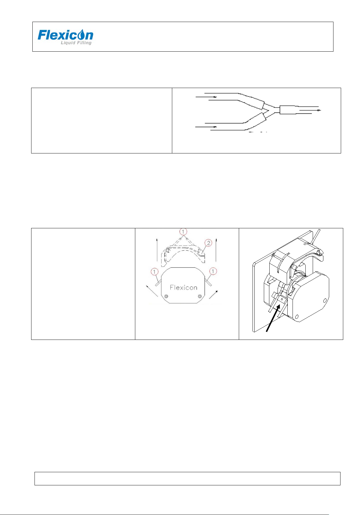
4.4 Assembly of tubes and Y-connectors
Before mounting the tubes in the dispenser head
the tubes must be assembled with a Y-con nec tor .
When the Y-connector has been assembled,
mount the tubes in the dispenser head, as shown
in 4.5
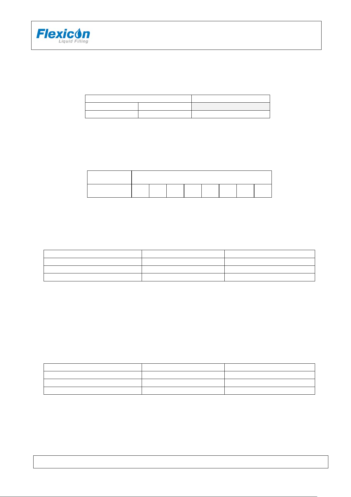
4.5 Mounting of silicone tubes
PF6 is equipped with tube bridges and tube locks. The tube locks ensure that the mounted tubes do
not slide through the pump head when dispensing.
The tube bridge retains the tube and performs the necessary pressure on the tubes.
Each set of tubes and y-connector must be assembled as
Open the dispenser head by tipping
each of the two locking pins up (1)
and lift the tube bridge (2)
Mount the wanted tube size
together with the matching tube
lock.
Press down the two locking pins (1)
Never leave the dispenser mounted
with tubes overnight.
At least tip the locking pins (1) up in
order not to retain the tube in
pressure.
Opening the dispenser
Fig. 8 – Mounting of silicone tubes
PF6 IH EN 74-105-022 v1.04.doc Version: 1.04 Page 11 of 30
Page 12

INSTRUCTION HANDBOOK
1
3
PF6
Mount he correct tube lock (1) on
its dowel pin and place the tubes
in the dispenser head.
The Y-connector must be situated
to the right of the dispenser head.
It is important that the tubes are
situated in the two notches (2+3).
Now place the tube bridge in its
tracks and engage the two locking
pins.
2
4.6 Dispensing
4.6.1 Prime tubes
When the tubes and Y-connectors have been assembled and mounted in the pump head, the tubes
must be primed; priming tubes have the purpose of filling the tubes with the product.
First, place the product container.
Hold a collecting bowl under the filling nozzle(s) press the prime button.
Check that the tubes are free of bubbles and that the end of the tubes on the suction side, are under
the liquid surface. The suction tubes must not have contact with the container body.
4.6.2 Problems with drips
During filling drips can cause incorrect filling volumes and that the area underneath the filling nozzle
becomes contaminated. If drips occur the following can be tried:
choose a smaller filling nozzle
decrease speed
increase acceleration
use reversion
mount a non-return v alve
4.6.3 Problems with hard feed
When dispensing with small tubes, counter pressure on the pressure side of pump head might
constitute inaccuracy and instability in filling (hard feed). In some cases the problem can be resolved
by using a larger tube on the pressure side (after Y-connector).
PF6 IH EN 74-105-022 v1.04.doc Version: 1.04 Page 12 of 30
Page 13

INSTRUCTION HANDBOOK
PF6 Vx.x © Flexicon’05
PRESS GO TO CONTINUE..
FUNCTION NO. : __
F 1: VOLUME (ml) : 100.00
PF6
4.7 Starting the PF6
Turn the PF6 on.
Fig. 9 – Starting PF6 -1
Press the <GO> key and the display will show the following:
Fig. 10 – Starting PF6 -2
The values displayed in the status lines will be the above or the latest values used.
PF6 is now ready for setting of runtime parameters.
In the following, the sign <> will mean that the indicated key must be activated.
For instance, <ENT> means that ENTER must be pressed.
4.7.1 Setting of runtime parameters
The PF6 is function-controlled and each parameter has its own function number.
The function is called by entering the number and pressing <ENT>.
This can be done independently of the position of the cursor on the status lines.
4.7.2 Parameters
In the following a parameter will be the value of a single function, e.g. volume, velocity, number of
fillings etc.
4.7.3 Programs
In the following description a program will be a complete set of runtime parameters, which together
will constitute the PF6 work instructions.
4.7.4 General information on the setting of parameters of the PF6
The PF6 is equipped with a battery in the memory and will therefore always remember the
programmed parameters, even if the main isolator is turned off.
This also means that when a function is called, the value last used will be suggested. The value may
be overwritten or approved by pressing <ENT>.
The setting of parameters is done using functions. Each parameter has its own function number.
PF6 IH EN 74-105-022 v1.04.doc Version: 1.04 Page 13 of 30
Page 14

INSTRUCTION HANDBOOK
PF6
The setting of a parameter is carried out by entering the corresponding function number followed by
"ENT".
This will make the required function appear in the prompt line of the display and show the current
value or information of the function.
This value will automatically be overwritten when entering a new value. After being entered, the new
value will be shown in the prompt line. The new value is entered into the computer by pressing "ENT".
The new value will be shown in the status lines at once.
Example:
If a volume of 8.5 ml is required, the following should be entered:
<1>+<ENT>+<8>+<.>+<5>+<ENT>
4.7.5 Used as a filler
Example of filling job:
Volume: 8.5 ml.
Tube: 3.2.
Velocity: 400 rpm.
Acceleration: 100.
Back suction: 1
100 fill to be completed.
A delay of 1.1 seconds between each filling.
Product has a specific gravity 1.0
The above job should be programmed as follows:
Volume: <1>+<ENT>+<8>+<.>+<5>+<ENT>
Tube: <2>+<ENT>+<3>+<.>+<2>+<ENT>
Velocity: <3>+<ENT>+<4>+<0>+<0>+<ENT>
Acceleration: <4>+<ENT>+<1>+<0>+<0>+<ENT>
Back suction: <5>+<ENT>+<1>+<ENT>
Number of fills: <6>+<ENT>+<1>+<0>+<0>+<ENT>
Delay: <7>+<ENT>+<1>+<.>+<1>+<ENT>
Specific Gravity <9>+<ENT>+<1>+<.>+<0>+<ENT>
You have now programmed the PF6 for the job, but want to reset the built- in counters. In function 8
the counters indicate "number of completed fills".
Number of fills: <8>+<ENT>+<C>+<ENT>
Now inform PF6 that you want to enter filling mode by pressing <disp.>.
Every time <GO> or the foot switch is pressed, or every time an electric signal is given, PF6 will run
100 fills of 8.5 ml with a delay of 1.1 seconds between the fills.
Press <GO>, verify that PF6 starts and let it run.
Press ARROW DOWN until you see function 8 on the status line and that F8: is counting each fill.
F10: gives a current indication of the number of fills completed per minute.
The fills have not been calibrated. For this function, please see chapter 5 of this manual.
PF6 IH EN 74-105-022 v1.04.doc Version: 1.04 Page 14 of 30
Page 15

INSTRUCTION HANDBOOK
PF6
4.8 Stop filling
When PF6 has completed the number of fills asked for in F6: it will stop automatically. If <GO> is
pressed again, PF6 will complete the programmed number of fills once more.
If you want to stop the filling before the programmed number has been completed, press <STOP>,
and PF6 will stop after completing the filling in progress.
The filling series can be completed by pressing <GO>.
If you want to stop IMMEDIATELY, such as in the middle of a fill, press <STOP> twice, and PF6 will
stop immediately.
The filling series can be completed by pressing <disp.>+<GO>, and the interrupted filling will be
included.
4.9 Used as a pump
PF6 can also be used as a pump.
In this case only velocity should be entered.
Start the pumping by pressing <pump>+<GO>.
PF6 will start and run the required number of revolutions per minute.
PF6 will pump at this velocity until stopped by pressing <STOP>.
4.10 Used with a bottle handling system
PF6 can also be used together with a bottle handling system like FF20/FF15 from Flexicon.
When PF6 is integrated in an automatic bottle handling system, it is important to observe the
following:
The batch size in case of running with a bottle handling system must be set to 1.
The PF6 should be in dispense mode before starting the filling sequence.
The Go signal which activates filling should be generated by the bottle handling system.
The Go signal should be inserted into PF6 via External Go port (see section 10.1)
PF6 IH EN 74-105-022 v1.04.doc Version: 1.04 Page 15 of 30
Page 16

INSTRUCTION HANDBOOK
CALIB. WEIGHT : 0.0000__
F 1: VOLUME (ml) : 8.50
PF6
5 Calibration
As the environment of the PF6 may vary from time to time and as tubes and products have small
tolerances, it is necessary to calibrate the drive when it is started. Recalibration is necessary during
production.
If the quantity has been entered as volume in ml, a measuring cylinder or a balance may be used as a
control and measuring unit. The balance will always be the more accurate, especially for small
quantities.
5.1 Initial volume calibration
If a volume has been entered in function 1, and a completed fill is measured with a balance, the
specific gravity of the liquid in question is to be entered in function 9.
(The parameters already entered may be used for a trial).
Prepare the balance by tarring the container and make sure that the tubes are completely filled, up to
and including the filling needle.
It is recommended to let the filler complete a few fills before the calibration is carried out.
Keep the tarred container below the filling needle and complete a single fill by pressing
<calib>+<GO> and PF6 will now ask for the completed volume showing the following display:
Fig. 11 – Calibration
In the prompt line, PF6 asks the weight, and the WEIGHT of the trial fill in question must be entered,
for example. 8.12: <8>+<.>+<1>+<2>+<ENT>
After calibration, complete a few fills and draw off a sample and check the volume.
If the volume is not at the level desired, carry out a re-calibration as described below.
Function 8 should now be reset, and the filling may be started by pressing <disp.>+<GO>.
5.2 Re-calibration
During production it may be necessary to recalibrate the volume dispensed by the filler to compensate
for changes in the environment e.g. the liquid level of the feed vessel will sink. This re-calibration may
be carried out without stopping the filling.
IT IS IMPORTANT TO USE THE SAME MEASURING METHOD FOR THE RECALIBRATION AS
USED FOR THE INITIAL CALIBRATION.
Draw off a filled sample and measure it. If the volume is not at the level desird, press <calib> + <Ent>
and then insert the measured value. Subsequently, let the production continue and draw off a sample
to check the volume again.
PF6 will now automatically adjust the subsequent fills.
PF6 IH EN 74-105-022 v1.04.doc Version: 1.04 Page 16 of 30
Page 17

INSTRUCTION HANDBOOK
6 Description of PF6 functi ons / par ame t e rs
6.1 List of functions
1. Volume 21. Batch no.
2. Tube diameter 24. Print status
3. Velocity 29. Print param. (print parameters)
4. Acceleration/deceleration 31. Save program
5. Reverse (back suction) 32. Load program
6. Batch Size 33. Delete program
7. Delay 34. Print programs
8. Fillings (Completed fills) 46. Language
9. Sp. Grav. (Specific gravity) 47. Printer-setup
PF6
10. Fills pr. Minute (Output rate) 72. Volume format
15. Input mode 80. Reset memory
20. Operator
PF6 IH EN 74-105-022 v1.04.doc Version: 1.04 Page 17 of 30
Page 18
Value
Option
Min
Max
0.01
9999.9
ml. or gram
Tube Sizes
Max. Velocity
Max. acceleration
0.5 - 0.8 – 1.2 – 1.6
400
100
3.2
400
100
4.8 - 6.0 – 8.0
400
100
Tube Sizes
Max. Velocity
Max. acceleration
0.5 - 0.8 – 1.2 – 1.6
400
100
3.2
400
100
4.8 - 6.0 – 8.0
400
100
Function 1 - Volume
Value: ml
Function 1 informs the system of the volume to be filled.
The entered value must be between 0.01 and 9999.9.
Function 2 - Tube diameter
Value: Inside diameter of the tube in mm.
Drive type Tube inside diameter in mm
PF6 0.5 0.8 1.2 1.6 3.2 4.8 6.0 8.0
Function 3 - Velocity
Value: Revolutions per minute (rpm).
Velocity range depends on tube size applied.
Range:
INSTRUCTION HANDBOOK
PF6
The fastest filling will be carried out at the highest velocity setting but the velocity should always be
adjusted to suit the characteristics of the product and to reduce splashing or foaming.
Function 4 - Acceleration/deceleration
Value: An integer number.
This function offers a choice of values between 1 and 100 dependent on the tube size and drive;
1 = slowest, 100 = fastest.
PF6 IH EN 74-105-022 v1.04.doc Version: 1.04 Page 18 of 30
Page 19

INSTRUCTION HANDBOOK
PF6
Function 5 - Reversing (back suction)
Value: An integer number.
After each filling the pump head can be set to perform a small back suction to prevent dripping.
The back suction can be set at values between 0 and 10.
0 = no back suction
10 = maximum back suction
The value has no relation to any other parameters and is solely a number of degrees of a rotor turn.
Consequently, the volume that is sucked back will depend on the tube diameter.
Function 6 – Batch size
Value: An integer number.
Enter the number of fills you want the filler to perform when started by <GO>, foot switch or via
electrical signal. Any number of fills between 1 and 65,000 can be selected.
Function 7 – Delay
Value: Seconds.
If more than one fill is chosen in function 6, enter the required delay between the fills.
The value of the delay can range between 0.1 - 25.0 seconds, with a graduation of 0.1 second.
Function 8 – Fillings (completed fills)
Value: An int eger number
Nothing can be entered in this function as it only displays the number of fills completed since the
latest reset of the function.
To res et this function: Press the keys <8>+<ENT>+<C>+<ENT>
Function 9 – Specific gravity
Value: Numerical
The specific gravity of the product used can be entered here.
Default value for this function is 1.0000 g/ml.
The PF6 uses this value to obtain the volume in F1, when volume mode is used.
Changing specific gravity should be followed by a calibration.
Function 10 – Fills pr. Minute (Output rate)
Value: Number of fills per time unit.
Nothing can be entered in this function as it only displays the current output.
The function displays how many fills the system carries out per time unit.
The function operates as follows: The PF6 records the precise time between two fills via the built-in
clock, and calculates the number of fillings per time unit.
The display is updated at the completion of each fill.
The function can be called up for viewing, but it cannot be reset and values cannot be entered in this
function.
PF6 IH EN 74-105-022 v1.04.doc Version: 1.04 Page 19 of 30
Page 20

INSTRUCTION HANDBOOK
PF6
Function 15 – Input mode
Value: 1 or 2
1 = The foot switch will only function as a starter.
2 = First press on the foot switch starts the filler.
Second press on the foot switch stops the filler.
Third press on the foot switch starts the filler.
Function 20 – Operator
Value: An int eger number
The maximum number of digits in an operator number is 10. This means that an operator number is
an integral number between 0 and 999999999999.
With this function it is possible to inform the system which operator is in charge of the current
production. The operator number entered will always appear on print-outs of the log (F24) and the
operating parameters (F29).
Function 21 – Batch no.
Value: An int eger number
The maximum number of digits in a batch number is 10. This means that a batch number is an
integral number between 0 and 999999999999.
With this function the operator can inform the system of the batch or production number under which
the current production is recorded. The batch number entered will always be shown on print-outs of
the log (F24) and print-outs of the operating parameters (F29).
Function 24 – Print status
If a printer is connected, this function will start the printing of the current production status.
Function 29 – Print param. (print parameters)
This function prints the current parameters via the connected printer.
The print-out is for the current drive or all the current drives.
When the function is called, the system will ask the following questions:
PRINT PARAM (Y/N)
For print-out of the current drive only, press <Y>.
For print-out of all connected drives, press <N>.
Function 31 – Save program
Saves a complete set of parameters as a program.
It is possible to save up to 5 sets of parameters in the memory.
If a particular set of parameters is used frequently, it is a good idea to store the se ttings in orde r to
allow their easy retrieval as a complete filling program. This also ensures that exactly the same
parameters are used each time thereby reducing the risk of programming error.
PF6 IH EN 74-105-022 v1.04.doc Version: 1.04 Page 20 of 30
Page 21

INSTRUCTION HANDBOOK
PF6
It is important that all parameters are entered and that these parameters are checked before saving
the program saved via Function 31.
The system will always suggest the first available number in a range between 1 and 5.
If this number is to be accepted as the program number, press <ENT>, and all parameters will be
saved under this program number.
If another number is required, enter the number chosen, and if this number is free, the program is
saved by pressing <ENT>.
If the number is occupied by a program already saved, user is asked whether to overwrite the
program already saved.
Function 32 – Load program
Loads a program already saved and overwrites the current parameters with the values of the
program.
By pressing the required program number followed by <ENT>, the operating parameters saved under
the specified program number will be entered as the current parameters under the respective
functions.
If program number 0 is selected, the function is left without loading a program and the system will
keep the current values.
Function 33 – Delete program
If a complete program is to be deleted, this can be done by overwriting it via Function 31, or the
program can be deleted via Function 33.
When pressing the required program number followed by <ENT> the specified program will be
deleted.
If a number is entered under which no program is saved, the system will not accept it and the number
must be corrected, or the function can be left by pressing <0>+<ENT>.
Function 34 – Print program
This function prints the individual parameters in all the programs stored in the memory.
When pressing <N> the system will leave the function, without carrying out the function. When
pressing <Y> the system will start printing the parameters in all programs saved.
Function 46 – Language
Value: An integer number.
This version offers a choice of two languages.
1 - English
2 - German
The languages will be active on the display and on the print-outs.
PF6 IH EN 74-105-022 v1.04.doc Version: 1.04 Page 21 of 30
Page 22

INSTRUCTION HANDBOOK
75
300
2000
110
600
2400
134
1200
4800
150
1800
9600
Function 47 – Printer set-up
Function 47 tells the system which protocol to use when transmitting to connected printer.
When this function is activated, it will first require the operator to enter the transmission velocity
(baudrate).
One of the following values must be chosen:
Subsequently PF6 will ask the operator to enter a protocol number (controlword).
There is a choice between the following protocols:
1 = 7 data bits 1 stop bit no parity
PF6
2 = 7 data bits 1 stop bit even parity
3 = 7 data bits 1 stop bit odd parity
4 = 7 data bits 2 stop bits no parity
5 = 7 data bits 2 stop bits even parity
6 = 7 data bits 2 stop bits odd parity
7 = 8 data bits 1 stop bit no parity
8 = 8 data bits 1 stop bit even parity
9 = 8 data bits 1 stop bit odd parity
10 = 8 data bits 2 stop bits no parity
11 = 8 data bits 2 stop bits even parity
12 = 8 data bits 2 stop bits odd parity
It is not possible to set the system to transmit at any other rates or formats.
Function 72 – Volume format
Value: An integer number.
Volume format for “function 1”.
The function makes it possible to change volume format between 1: volume (ml) and 2: weight (g).
PF6 IH EN 74-105-022 v1.04.doc Version: 1.04 Page 22 of 30
Page 23

INSTRUCTION HANDBOOK
PF6
Function 80 – Reset memory
This function will reset the memory with the exception of the part used for saving programs.
The PF6 will enter stand-by mode, and when switched on again the built-in parameters will be valid.
IF THE PF6 DOES NOT WORK OR DOES NOT OPERATE AS EXPECTED, ACTIVATE FUNCTIO N
80.
7 Print-outs
PF6 can be connected to a printer (via RS-232) which can produce three different types of print-outs.
7.1 Print current parameters
Function 29 prints the current parameters, and print-outs should be made after programming and
calibrating PF6 and resetting function 8.
The print-out is started in the following way: <2>+<9>+<ENT>
Press the <Y> key to confirm start of printing, and the printer will start.
7.2 Print current status
Function 24 prints the current status, and print-outs should be made after completion of the filling
series.
The printing is to be started in the following way: <2>+<4>+<ENT>.
Press the <Y> key to confirm start of printing, and the printer will start.
After the status print-out the printer memory is deleted automatically.
7.3 Print programs
Up to five programs can be stored in PF6, and a list of saved programs can be printed by means of
function 34.
The printing is to be started in the following way: <3>+<4>+<ENT>
Press the <Y> key to confirm start of printing, and the printer will start.
PF6 IH EN 74-105-022 v1.04.doc Version: 1.04 Page 23 of 30
Page 24

INSTRUCTION HANDBOOK
Cleaning of parts
May
autoclaved
Can be cleaned
alcohol 70%
Can be cleaned with
wiped off with dry a cloth
Stainless steel
AISI304
Stainless steel
AISI316L
Anodized aluminium
Silicone tubes /
X**
times
PF6
8 Cleaning
8.1 Cleaning Frequency
As PF6 is not in direct contact with the dispensed product, daily cleaning might not be necessary.
Cleaning might be determined by local sop’s and cleaning validations; but must never be with
detergents more potent than the ones below.
8.2 Preparations for cleaning
Before cleaning the machine:
Turn off the power
Remove the tube bridge
Remove the tubes
8.3 Cleaning Guidance
Correct cleaning of the PF6 is carried out by washing it off with water or detergents, using a lint-free
firmly wrung cloth or lint-free paper towel; subsequently the machine is wiped off with a dry cloth.
8.4 Detergents or cleaning agents
Normal cleaning agents such as tepid/medium hot water, ethyl alcohol (ethanol) 70% and may be
used all over the machine.
The PF6 consists of stainlees steel and anodized aluminium, and can be cleaned in several ways:
made of:
Y-connectors
Examples:
Flexicon silicone tubes can be autoclaved
PF6 has a membrane-type keypad. The keypad is sealed and flat and can be cleaned with
alcohol or water.
**Recommendation:
Keep a log on the cleaning in order to keep a sense of perspective.
be
X X X
X X X
X X X
Max 10
with ethyl
X X
water and afterwards
PF6 IH EN 74-105-022 v1.04.doc Version: 1.04 Page 24 of 30
Page 25

INSTRUCTION HANDBOOK
9 Maintenance & service
9.1 Daily maintenance
PF6 does not require any special daily maintenance, such as lubrication or the like.
9.2 Service
Should service be needed, please contact W-M Flexicon or your local supplier.
9.3 Methods and frequency of inspections for safety functions
Safety functions should be tested once a year:
Tube Bridge
Remove the tube bridge and press PRIME.
The machine must not start if the tube bridge is not present.
Keep a log and read the previous log recordings to present an overview of the machines state.
After testing the safety functions the results must be recorded in the log.
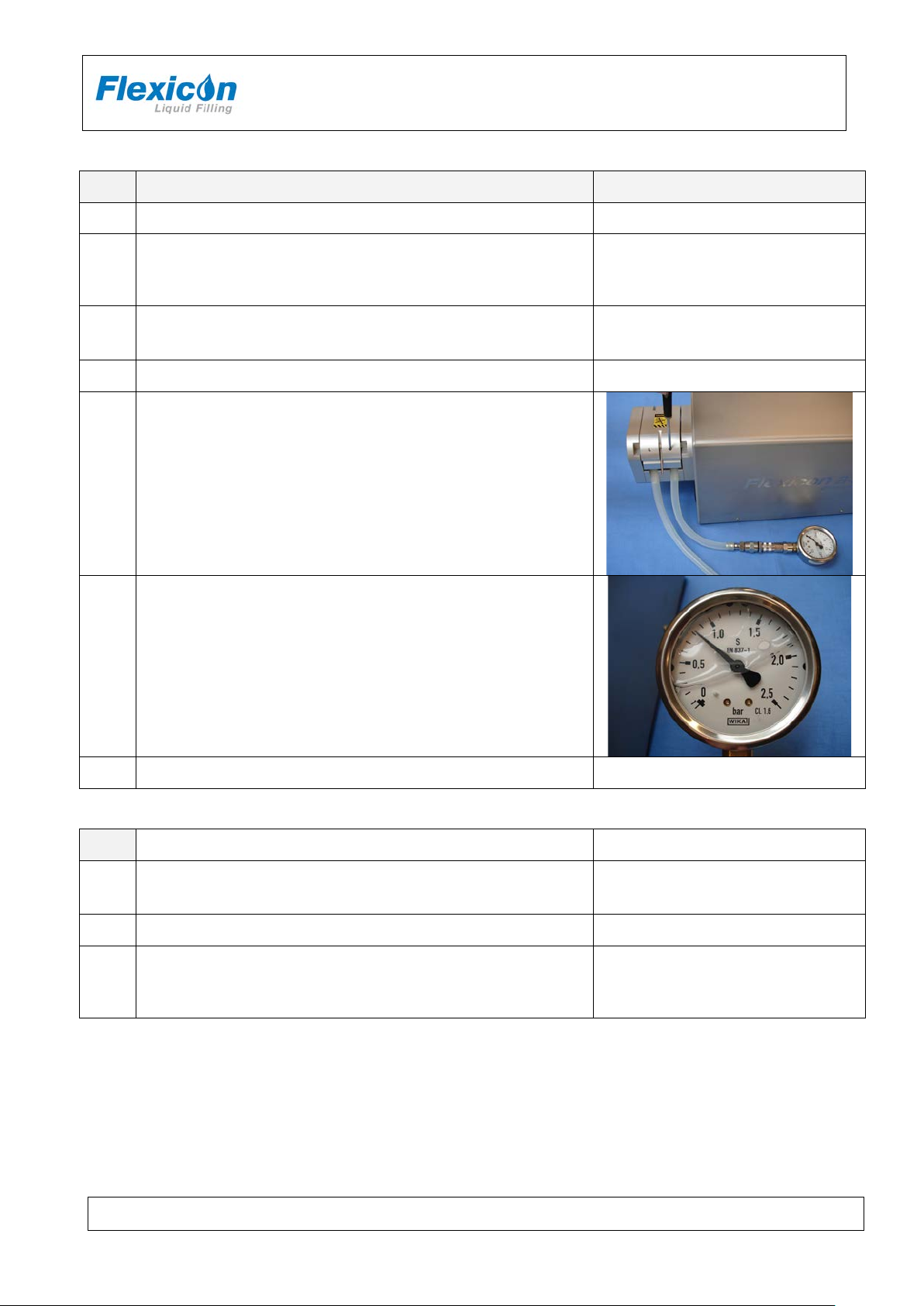
9.3.1 Mechanical adjustments Pump pressure
For adjustment of pump pressure for PF6 you will need the following:
• Pressure gauge suitable for measur ing 0.8 - 0.9 bar and 3.0 - 3.5 bar
• Ø1.6 ID tube (app 0.5 m)
• Ø8.0 ID tube (app 0.5 m)
• Screwdrivers
• Loctite 2400
Illustration
PF6
Adjustment screws (A) for spring
force.
Stops (C).
PF6 IH EN 74-105-022 v1.04.doc Version: 1.04 Page 25 of 30
Adjustment screws (B) for
maximum pump pressure.
Page 26
INSTRUCTION HANDBOOK
Note that adjustment screws B are
force.
Mount Ø8.0 ID tubes in the pump (2 separate pieces of tube
pump.
Mount Ø1.6 ID tubes in the pump (2 separate pieces of tube
pump.
NA
NA
Connect pressure gauge to outlet end of tube and measure
The 2 “channels” must be adjusted separately.
NA
Adjusting the spring force
Step Action Remarks / control
1. Remove the pads covering the adjustment screws. NA
PF6
Screw down the adjustment screws (B) until the upper side of
2.
3.
4. Set speed for 100 rpm and start the pump. NA
the stops (C) are aligned with the intermediate part of the pump
head.
open at both ends). Observe that tubes lay correctly in the
Connect pressure gauge to outlet end of tube and measure
outlet air pressure.
5.
The 2 “channels” must be adjusted separately.
Adjust the spring force action on the tubes by use of adjustment
screws (A).
6.
The outlet air pressure should be adjusted to 0.8 – 0.9 bar.
locked by use of glue. Use a suitable
screwdriver and use necessary
NA
7. Stop the pump NA
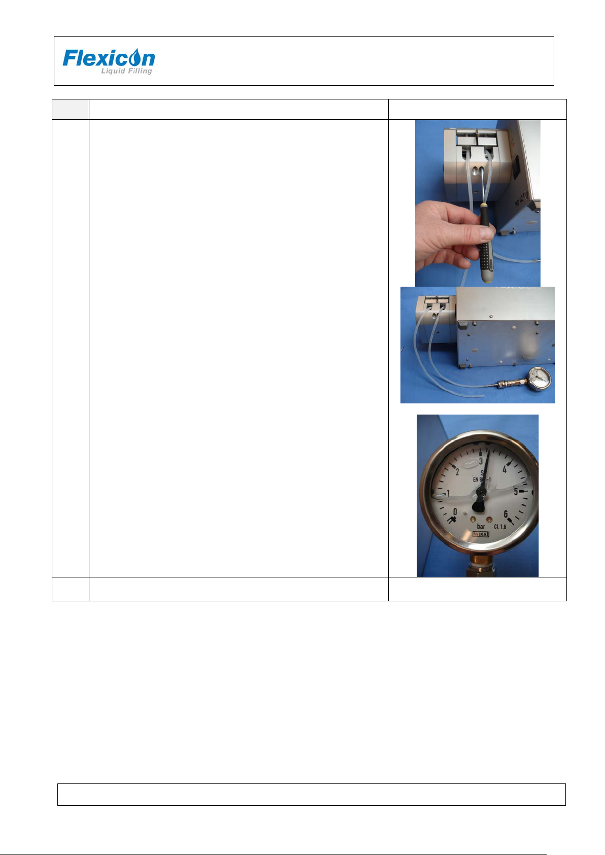
Adjusting the pump pressure
Step Action Remarks / control
1.
open at both ends). Observe that tubes lay correctly in the
2. Set speed for 100 rpm and start the pump.
outlet air pressure.
3.
PF6 IH EN 74-105-022 v1.04.doc Version: 1.04 Page 26 of 30
Page 27
INSTRUCTION HANDBOOK
Should it become necessary to put in new glue, use a “soft”
glue like Loctite 222.
Step Action Remarks / control
Adjust the screws (B) for control of maximum pressure.
4.
The outlet air pressure should be adjusted to 3.0 – 3.5 bar.
PF6
5
PF6 IH EN 74-105-022 v1.04.doc Version: 1.04 Page 27 of 30
Page 28

INSTRUCTION HANDBOOK
INPUT FOR START SIGNAL
+5 - 50 VDC, min. 100 msec. positive-edge-trigged.
STATUS OUTPUT, MAX. +24 VDC, 100 MA.
Pin 4 is grounded via an open collector during filling.
10 Interface and change of volta ge
10.1 PF6 interface; External GO
"External GO" is designed as a 5-pin DIN plug with the following PIN configuration:
PIN 1:
PIN 2: OUTPUT, +24 VDC, MAX. 250 mA.
PIN 3: GROUND.
PIN 4:
PIN 5: STATUS OUTPUT, MAX. +24VDC, 100 mA Pin 5 is complementary to pin 4.
10.2 PF6 interface; RS-232
RS-232 has a 9-pin SUB-D plug:
PF6
PIN 1:
PIN 2:
PIN 3:
PIN 4:
PIN 5:
PIN 6:
PIN 7:
PIN 8:
PIN 9:
No connection
Receive data
Transmit data
+12 VDC (at 1 kOhm)
Ground
No connection
Request to send
Clear to send
No connection
PF6 IH EN 74-105-022 v1.04.doc Version: 1.04 Page 28 of 30
Page 29
INSTRUCTION HANDBOOK
PF6
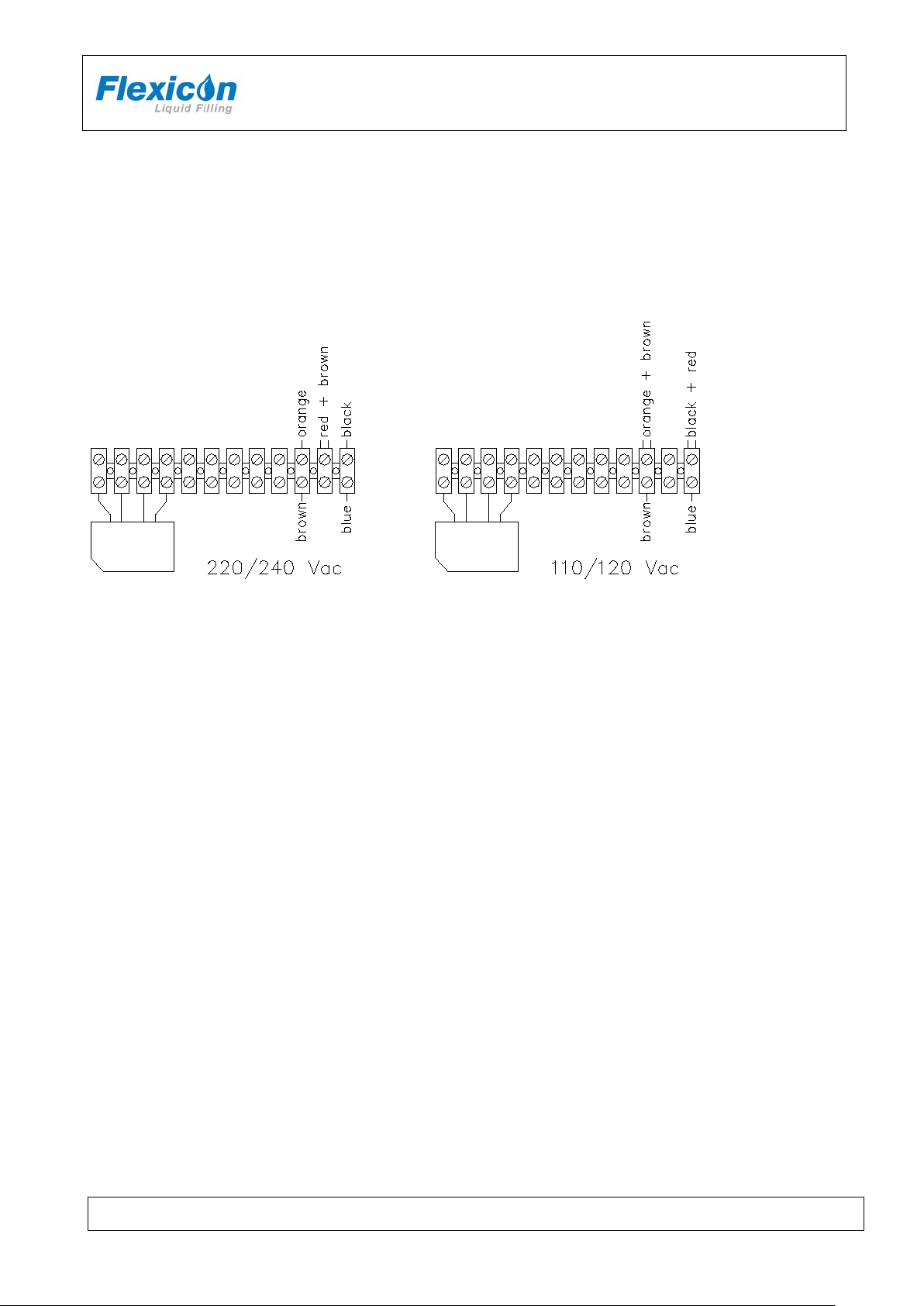
10.3 Change of voltage
The PF6 can be converted to accept another supply voltage.
The conversion can be made inside the machine by moving the cables of the transformer clamps.
Fig. 12 – Change of voltage
PF6 can be changed over to different main powers.
The change over is carried out inside the machine by moving the wires to the positions indicated in
fig. 12.
PF6 IH EN 74-105-022 v1.04.doc Version: 1.04 Page 29 of 30
Page 30

Made in Denmark
DS EN/ISO 12100
Safety of machinery - Basic concepts, general
principles of design
DS/EN 60204
Safety of machinery – Electrical equipment of
machines
2006/42/EC
On the approximation of the laws of the Member
States relating to machinery
2006/95/EC
On the harmonization of the laws of Member
for use within certain voltage limits
2004/108/EC
On the approximation of the laws of the Member
States relating to electromagnetic compatibility
Ringsted, Denmark
11 Declaration of conform ity
We Watson-Marlow Flexicon A/S
Frejasvej 2-6
DK-4100 Ringsted
Declare on our sole responsibility that the product:
PF6
INSTRUCTION HANDBOOK
PF6
2010
Model
Serial No.
Part No.
Supply: 230V / 50-60Hz / 50W
PF6
xxxx yyyy
91-050-008
to which this declaration relates is in conformity with the following standard(s):
According to the provisions in the Directives:
States relating to electrical equipment designed
Signature:
September 2010
Jørn Jeppesen, Development Manager
PF6 IH EN 74-105-022 v1.04.doc Version: 1.04 Page 30 of 30
 Loading...