

Page 1
Operators Manual
PF22
PF22 OM EN 74-132-005 v1.02.doc Version: 1.02 Page 1 of 34
Page 2

Operators Manual
PF22
1 DECLARATION OF CONFORMITY ......................................................................................... 3
2 CAUTION ................................................................................................................................. 4
3 GENERAL INFORMATION ...................................................................................................... 5
3.1 Use ....................................................................................................................................... 5
3.2 Unpacking and inspection ..................................................................................................... 5
3.3 The peristaltic principle .......................................................................................................... 5
3.4 Installation ............................................................................................................................. 6
3.5 Fitting of filling stand ............................................................................................................. 7
4 CONTROL ............................................................................................................................... 8
4.1 Filler lay-out........................................................................................................................... 8
4.2 Dispenser head ..................................................................................................................... 8
4.3 Display .................................................................................................................................. 9
4.4 Keyboard ............................................................................................................................. 10
5 PROGRAMMING ................................................................................................................... 11
5.1 Starting PF22 .......................................................................................................................11
5.2 Parameters ..........................................................................................................................11
5.3 Programs .............................................................................................................................11
5.4 General information on the prog r amming of PF22 .............................................................. 12
5.5 List of functions ................................................................................................................... 13
5.6 Description of functions ....................................................................................................... 13
6 DAILY USE ............................................................................................................................. 18
6.1 Vessel Placement ................................................................................................................ 18
6.2 Choice of tube ..................................................................................................................... 20
6.3 Assembly of Y-connectors ...................................................................................................
6.4 Tube assembly .................................................................................................................... 22
6.5 Used as a filler .................................................................................................................... 24
6.6 Stop filling............................................................................................................................ 25
6.7 Used as a pump .................................................................................................................. 25
6.8 Used with a bottle handling system ..................................................................................... 25
7 CALIBRATION ....................................................................................................................... 26
7.1 Volume calibration with measuring cylinder ......................................................................... 26
7.2 Initial volume calibration ...................................................................................................... 27
7.3 Re-calibration ...................................................................................................................... 27
8 PRINT-OUTS .......................................................................................................................... 28
8.1 Print current parameters...................................................................................................... 28
8.2 Print current status .............................................................................................................. 29
8.3 Print programs .................................................................................................................... 31
9 INTERFACE ........................................................................................................................... 32
9.1 External GO ........................................................................................................................ 32
9.2 RS-232 ................................................................................................................................ 33
9.3 Change of main power ........................................................................................................ 33
21
10 CLEANING AND MAINTENANCE ...................................................................................... 34
10.1 Daily cleaning ................................................................................................................... 34
10.2 Sterilisation ...................................................................................................................... 34
10.3 Maintenance .................................................................................................................... 34
PF22 OM EN 74-132-005 v1.02.doc Version: 1.02 Page 2 of 34
Page 3
Peristaltic dispenser
type
Model
PF6
61-050-022
PF22
61-220-000; 61-220-010
PD12I
61-150-022; 61-150-021
PD12IHS; PD12IDH
61-154-014
PD12P
61-151-022;
PD12PS
61-152-014; 61-152-020
PD22I
61-250-022
PD22P
61-251-022
PD22PS
61-252-022
EN55022
Information technology equipment - Radio
EN61000-6-2
Electromagnetic compatibility (EMC) - Part 6-2:
EN61000-6-3
Electromagnetic compatibility (EMC) - Part 6-3:
2006/42/EC
On the approximation of the laws of the Member
States relating to machinery
2004/108/EC
On the approximation of the laws of the Member
Jørn Jeppesen, Development Manager
1 Declaration of conformity
We Watson-Marlow Flexicon
Frejasvej 2-6
DK-4100 Ringsted
Declare on our sole responsibility that the peristaltic dispensers
Operators Manual
PF22
To which this declaration relates is in conf ormity with the following standard(s):
disturbance characteristics - Limits and methods of
measurement
Generic standards - Immunity for industrial
environments
Generic standards - Emission standard for
residential, commercial and light-industrial
environments
According to the provisions in the Directives:
States relating to electromagnetic compatibility
May 2012
Ringsted, Denmark
PF22 OM EN 74-132-005 v1.02.doc Version: 1.02 Page 3 of 34
Signature:
Page 4
2 Caution
This manual should be read before using the PF22.
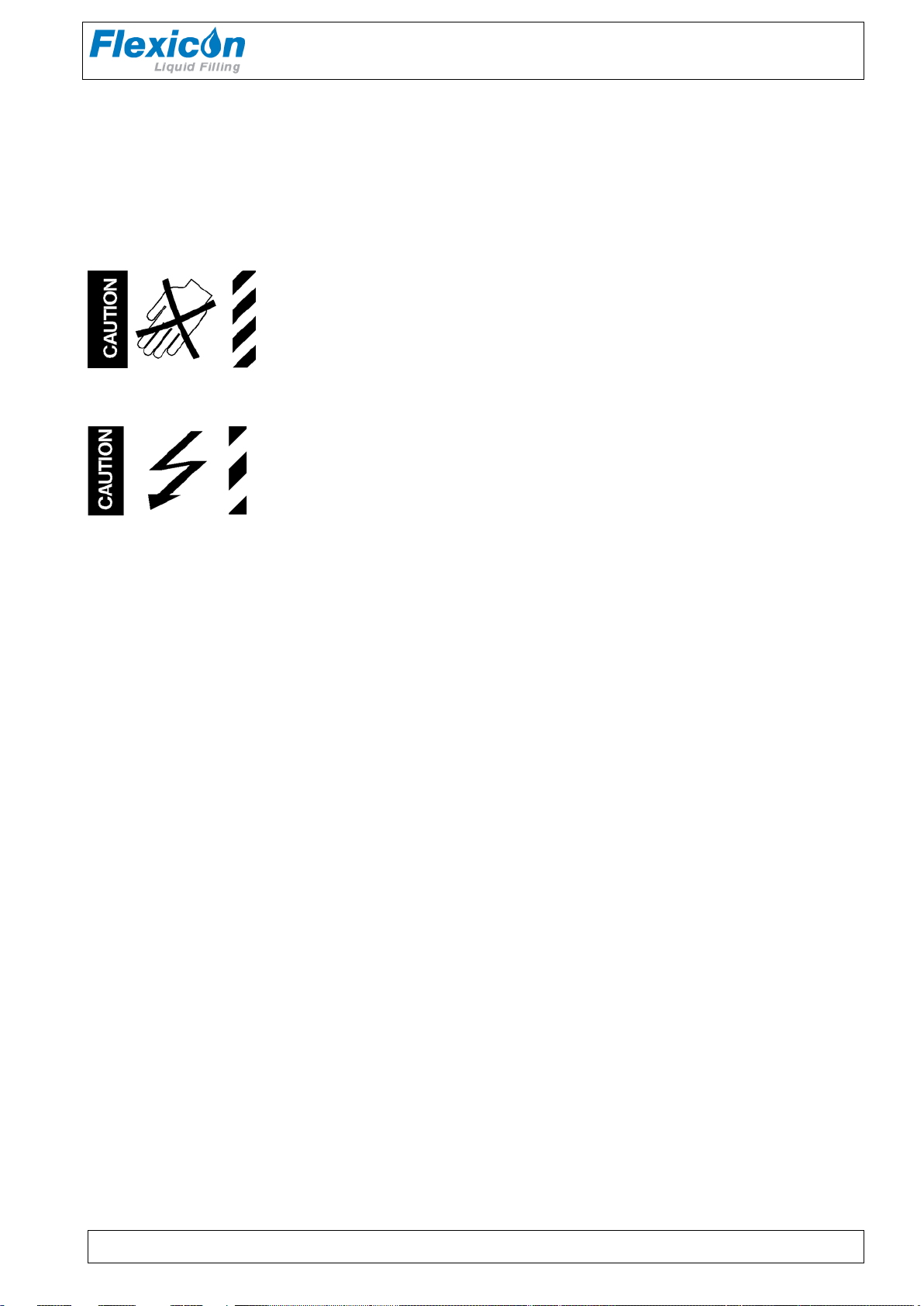
Explanations to the pictograms:
Warning against touching / Warning against opening:
Warning against high voltage:
Operators Manual
PF22
When operating the PF22, make sure that the Q C-dispenser head is properly assembled and the
locking pins are in closed position.
The main switch is used for emergency stopping .
The PF22 should only be used for dosing and filling of liq uid fluids.
The PF22 must be placed on a stable bed plate and should not be not exposed to great humidity,
high temperatures or other abnor m al oper at ing-environments. It is not to be used in explosion
hazardous environments.
It is prohibited to maintain or clean the PF22, when it is connected to the power supply.
It is prohibited for unauthorised per sonnel t o open t he cover of the PF22's electrical parts.
Always remember that the PF22 must be earthed by way of the switch.
Sound pressure level: L
< 70 dB(a)
Aeq
PF22 OM EN 74-132-005 v1.02.doc Version: 1.02 Page 4 of 34
Page 5

Operators Manual
3 General information
3.1 Use
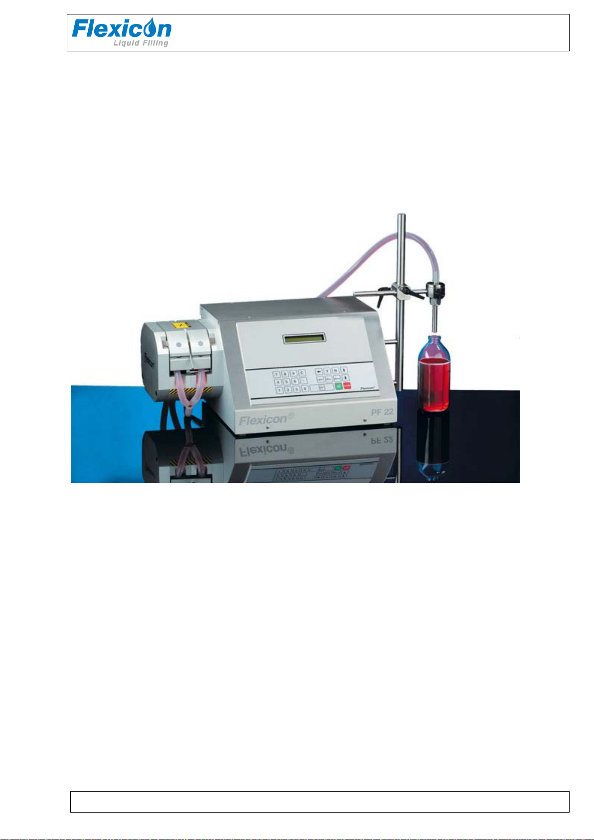
PF22 is a fully programmable, peristaltic filler ( dispenser ) which as a single unit can dispens e
liquids of volumes from 1 ml up to 9999. 9 m l.
PF22 has been specially developed for laboratory applications where extreme flexibility, frequent
product changes and absolute accuracy are key parameter s.
PF22 is programmable for a number of different applications, and full product ion docum entat ion
can be printed, if a printer is connected.
This manual contains all information necessary for the daily operation of the unit and so the PF22
manual should be read before using the f iller.
3.2 Unpacking and inspection
Please check that all ordered items have been received and that no items were damaged during
transport. In case of any defects or omissions, please contact Flexicon A/S or your local supplier
immediately.
When ordering spare parts, or accessories, for t he PF22, please state the serial number. The
serial number is stamped on the label on the rear of t he PF22.
ALWAYS REMEMBER that this machine must be earthed.
PF22
3.3 The peristaltic principle
PF22 operates with a peristaltic dispenser head (tube pump), where the liquid only comes into
contact with the flexible tube, the tube connections and the f illing needle. The tubes ar e usually
made of silicone, but other mater ials can also be used.
The dispenser head is designed in such a way that sterilised tubes can be assembled in the head
without affecting the sterility. Flexicon tubes are made of raw materials medically approved by the
FDA. The tubes are delivered in sealed packages and are provided with a batch number which
makes it possible to trace the tubes all the way back to t he r aw mater ial sour ce.
For this reason PF22 is specially suited for aseptic applications and for pr eventing crosscontamination. The dispenser head is self-priming, and the dispenser head itself can stand to be
run dry. It is recommended not to let the dispenser head be run dry for a long period WITH
CONNECTED TUBES, since this will lead to particle release.
A peristaltic dispenser head is not suitable for viscous products.
PF22 OM EN 74-132-005 v1.02.doc Version: 1.02 Page 5 of 34
Page 6
Operators Manual
3.4 Installation
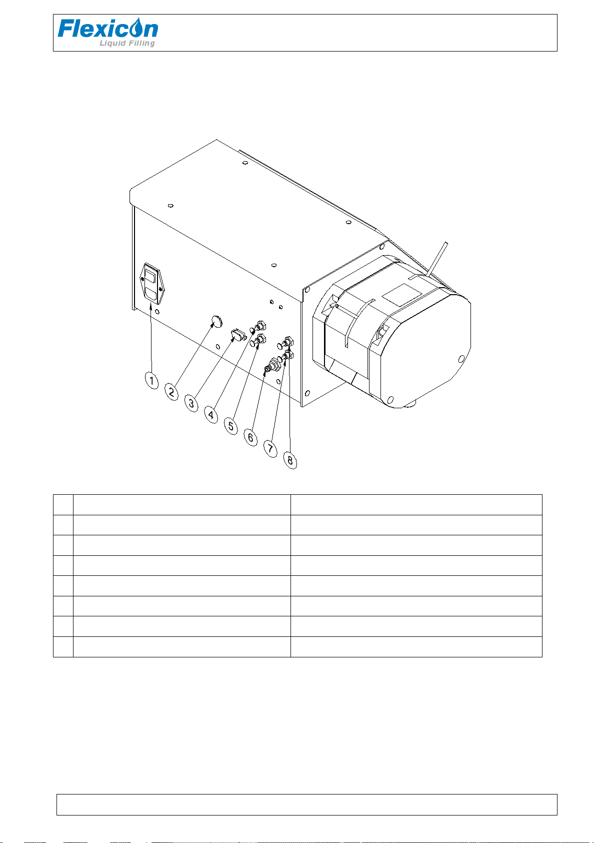
PF22 must be placed on a stable bedplate. All electrical connections are on its rear.
PF22
Fig. 3.1
1 Main Switch 230 Volts ac
2 External GO 5 way DIN
3 Printer Connection RS 232
4 (O) Air for nozzle with outside valve Pressure when Pump is running
5 (I) Air for nozzle with inside valve Constant pressure when machine is ON
6 Main air supply
7 (B) Diving Nozzle Bottom. Constant pressure when machine is ON
8 (T) Diving Nozzle Top Pressure when Pump is running
The main cable supplied is connected to the integrat ed m ain socket (1) in the main isolator, which
also contains master fuses. The plug is connected t o an ear thed switch.
External GO (2) is f or t he c onnect ion of a foot switch or for an external start ing s ig nal.
PF22 OM EN 74-132-005 v1.02.doc Version: 1.02 Page 6 of 34
Page 7
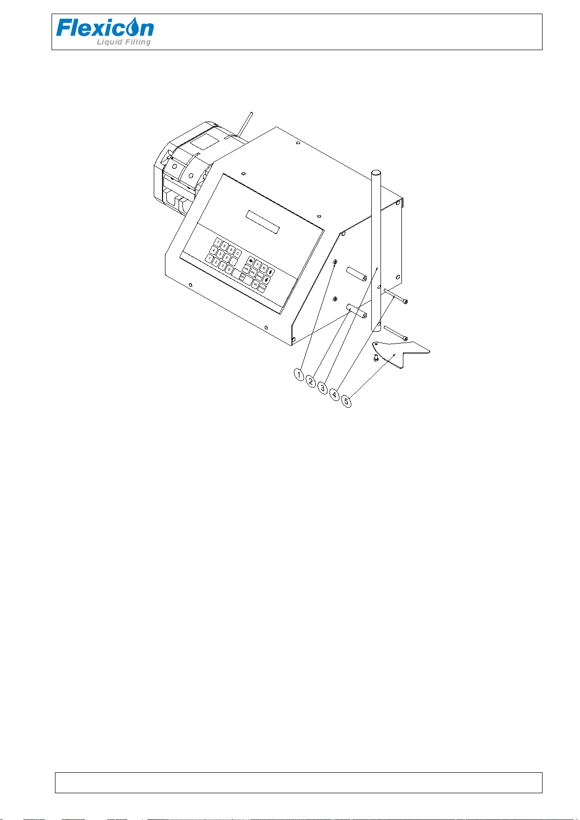
3.5 Fitting of fil ling stand
Operators Manual
PF22
Fig. 3.2
The filling stand is fitted as shown above.
First remove the screws (1)
Now you are able to fit the filling stand (4) by using the supplied distance tubes (2) and t he sc r ews
(3).
The bottle guide (5) can be turned upside / down for adj us t ing to low or high bottles or containers.
PF22 is now ready to be switched on and to be programmed.
PF22 OM EN 74-132-005 v1.02.doc Version: 1.02 Page 7 of 34
Page 8
4 Control
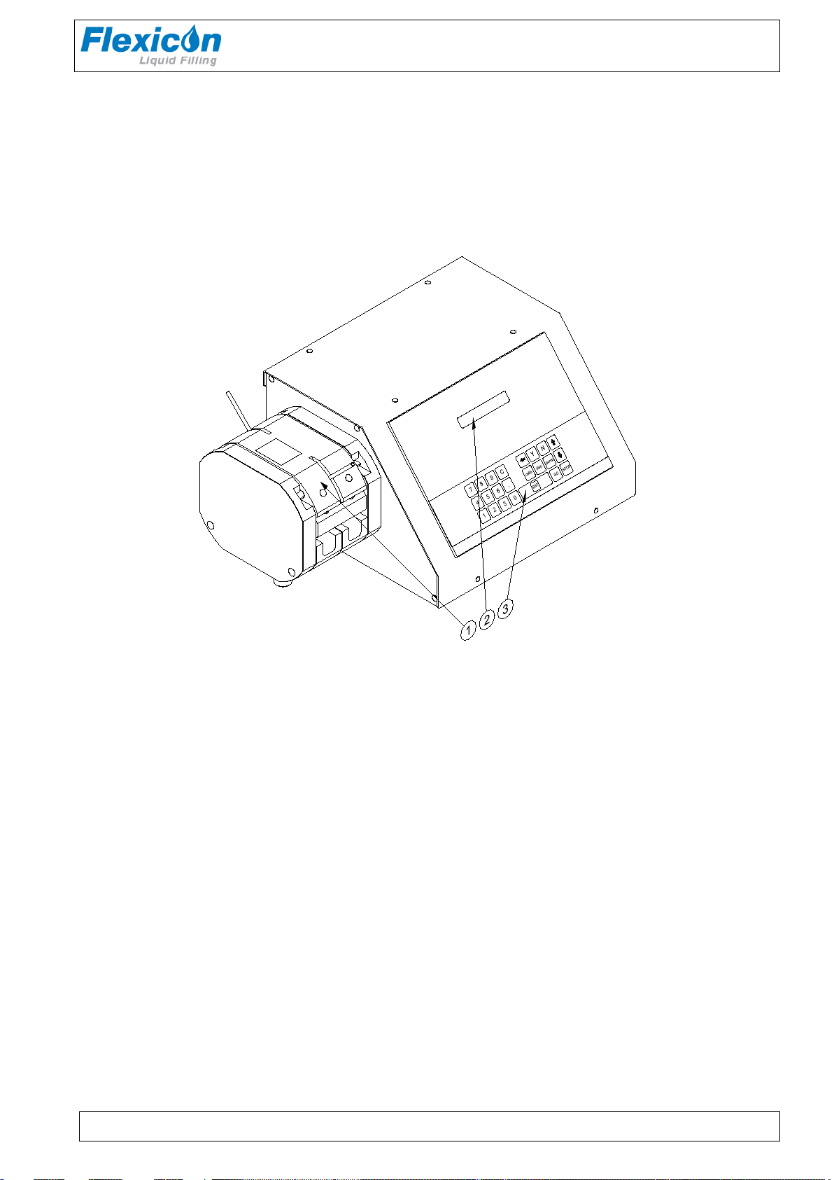
4.1 Filler lay-out
Operators Manual
PF22
Fig. 4.1
(1) Dispenser head
(2) Display
(3) Membrane-type keyboard
4.2 Dispenser head
The dispenser head can work with six different tube dimensions, and the head is eq uipped with a
"quick change" tube br idg e for rapid changeover between the different sizes.
The dispenser head works with two parallel tubes that are squeezed by six rollers mounted on ball
bearings. The rollers in the two sections are offset in order to eliminate pulsing.
PF22 OM EN 74-132-005 v1.02.doc Version: 1.02 Page 8 of 34
Page 9

Operators Manual
FUNCTION NO.:
F 1: VOLUME (ml): 100.00
4.3 Display
Fig. 4.2
The display of PF22 consists of 2 lines of 24 charact er s eac h and has cons tant bac kground
lighting.
There will always be a blinking cursor on the display showing where a character will appear, if a
key is activated.
The top line is the prompt line where PF22 communicates with the operator.
The bottom line is the status line that always shows the current operating param et er s . This status
line can be scrolled by pressing the UP or DOWN ARROW of the keyboard.
When operating PF22, it is VERY important to watch the top line constantly, as any current
question or instruction will be displayed here.
PF22
PF22 OM EN 74-132-005 v1.02.doc Version: 1.02 Page 9 of 34
Page 10
Operators Manual
7
4
1
8
5
2
9
6
3
C
.
0
calib.Ydisp.
STOPGO
pump
N
ENT
7
4
1
8
5
2
9
6
3
C
.
0
N
STOP
ENT
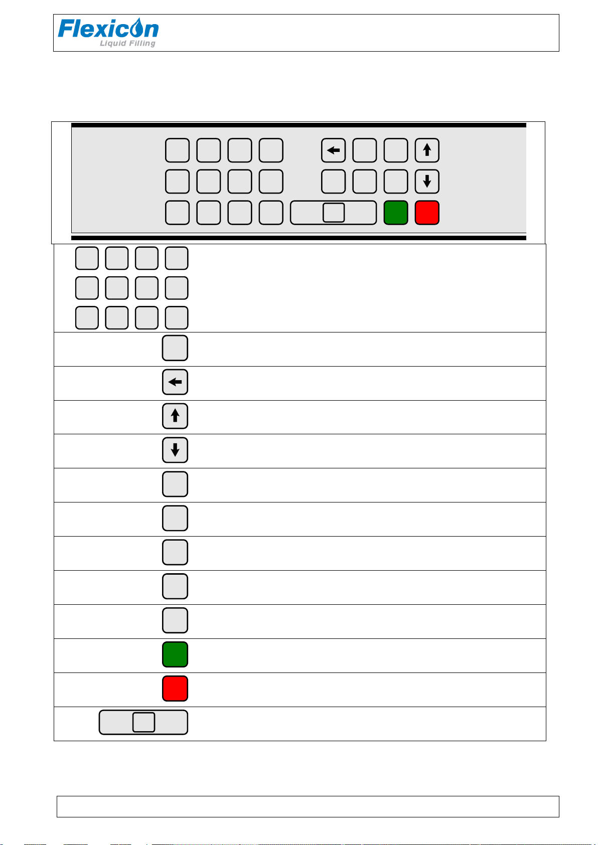
4.4 Keyboard
It is a foil-t ype k eyboard with built-in click. The keyboard is quite tight and plane and can be
cleaned with alcohol and other detergents.
Numerical keys 0 to 9 as well as decimal point.
PF22
C
Y
disp.
pump
calib.
“C” : Cancel
Delete Character to the left of the cursor
Scroll the status line one line up
Scroll the status line one line down
YES key for YES/NO qust ions on display
NO key for YES/NO qustions on display
Activates filling
Activates continous pumping
Activates calibration
GO
PF22 OM EN 74-132-005 v1.02.doc Version: 1.02 Page 10 of 34
Start Button
Stop Button
Enter / return to enter values typed on the k eyboard.
Fig. 4.3
Page 11

PF22 V1.1 (C) Flexicon’ 03
PRESS GO TO CONTINUE
FUNCTION NO.:
F 1: VOLUME (ml): 100.00
5 Programming
5.1 Starting PF22
When turning on the main switch, the display will show the following:
Press the <GO> key, and the display will show the following:
Operators Manual
PF22
The value shown in the status line will be the above or the latest value used.
PF22 is now ready to be programmed.
5.2 Parameters
In the following, a parameter will be the value of a single funct ion, for instance: volume, velocity or
number of fills.
5.3 Programs
In the following descriptions, a progr am will be a complete set of parameters which together will
constitute the PF22 work instructions.
PF22 OM EN 74-132-005 v1.02.doc Version: 1.02 Page 11 of 34
Page 12

Operators Manual
5.4 General infor m a t ion on the programming of P F22
PF22 is equipped with a battery in the memory and will therefore always remember the
programmed parameters, even if t he main isolator is turned off.
The programming is done using functions, i.e. every operating parameter has its own funct ion
number.
The programming is car r ied out by entering the function number followed by "ENT".
This will make the required function appear in t he pr om pt line of the display and show the current
value or information of the f unc t ion.
This value will automatically be overwritten when entering a new value.
After being entered, the new value will be shown in the prompt line. The new value is entered into
the computer by pressing "ENT".
The new value will be shown in the status line at once.
Example:
If a volume of 8.5 ml is r equired, the following must be entered:
<1>+<ENT>+<8>+<.>+<5>+<ENT>
PF22
PF22 OM EN 74-132-005 v1.02.doc Version: 1.02 Page 12 of 34
Page 13

5.5 List of functions
1. Volume
2. Tube dimension 20. Operator number
3. Velocity 21. Batch number
4. Acceleration/deceleration 24. Print status
5. Reversing (back suction) 29. Print parameters
6. Batch size 31. Save program
7. Delay 32. Load program
8. Completed fills 33. Delete program
9. Specific gravity 34. Print programs
10. Output rate 46. Set language
Operators Manual
PF22
15. Input mode 47. Printer set-up
18. Timer 2 72. Volume format
19. Timer 3 80. Reset memory
5.6 Description of func t ions
The individual functions will be described in the following:
1. Volume
Value: Choice of ml and grams.
Range: Required volume from 1 to 9999. 9 m l.
2. Tubes
Value: I ns ide diamet er ( i. d.) in mm
Range: 3.0 - 5.0 - 6.5 - 8.5 - 10.0 - 12.5
The tubes can be measured with the supplied tube gauge.
If the tube is changed, a new calibration must always be made.
3. Velocity
Value: Pum p r evolutions per m inut e ( r pm )
Range: 30 - 250 rpm
If the velocity is changed, a recalibration should be made.
4. Acceleration/deceleration
Value: An integral number
Range: 1 - 100
The acceleration and the deceleration will always be the same. The lowest value (1) will give the
lowest acceleration, and the highest value (100) will give the fastest acceleration.
If the acceleration is changed, a r ecalibration should be made.
PF22 OM EN 74-132-005 v1.02.doc Version: 1.02 Page 13 of 34
Page 14

Operators Manual
5. Reversing (back suction)
Value: An integral number
Range: 0 - 10
If the reversion is changed, a recalibration should be made.
6. Batch size
Value: Number.
Enter the number of f ills you want the filler t o per form when started by <GO>, foot switch or via
electrical signal. Any number of fills between 1 and 65,000 can be selected.
When the filler is operating in automatic system, where the system itself star ts t he filler each time
a bottle is in posit ion , THE VALUE I N THI S F UNCTION MUST ALWAYS BE 1.
7. Delay (Timer 1)
Value: Seconds.
If more than one fill is chosen in function 6, enter the required delay between the fills.
The value of the delay can range between 0.1 - 25.0 seconds, with a graduation of 0.1 second.
8. Completed fills
Value: Number.
Nothing can be entered in this function since it only displays the number of fills completed since
the latest reset of the function.
To reset this function, press the <C> key.
9. Specific gravity
Value: Decimal num ber.
Enter the specific gravity of t he liq uid in g / m l if the required volume was entered in Function 1 and
if this volume is controlled by balance. A re-c alibrat ion is necessary after entering the specific
gravity.
10. Output rate
Value: Number of fills per time unit.
Nothing can be entered in this function as it only displays the cur r ent output.
The function displays how many fills the system carries out per t im e unit . The time unit can be
HOUR or MINUT.
The function operates as follows:
The PF22 records the precise time between two fills via the built-in clock , and c alculates t he
number of fillings per tim e unit .
The display is updated at the completion of each f ill.
The function can be called up for viewing, but it cannot be r es et and values cannot be ent ered in
this function.
15. Input mode
Value: 1 or 2.
1 = The foot switch will only function as a starter.
2 = First press on the foot switch starts the filler.
Second press on the foot switch stops the filler.
Third press on the foot switch starts the filler.
PF22
PF22 OM EN 74-132-005 v1.02.doc Version: 1.02 Page 14 of 34
Page 15

Operators Manual
F29 PRN PARAM (Y/N):
18. Timer 2: Delay BEFORE filling with diving needle
Value: s econds
Range: 0.1 – 25 in increments of 0.1 seconds .
The timer is used to control the delay needed, when the PF22 is used in combination with a diving
needle.
The timer starts AFTER the GO signal is sent to the pump, to allow the diving needle to reach
bottom position before f illing star ts.
19. Timer 3: Delay AFTER filli ng with diving needle
Value: sec onds
Range: 0.1 – 25 in increments of 0.1 seconds .
The timer is used to control the delay needed, when the PF22 is used in combination with a diving
needle.
The timer starts after the pump has finished allowing the diving needle to return to top.
20. Operator number
An operator number can be entered in Function 20.
The maximum number of digits in an operator number is 10.
This means that an operator number is an int egral number between 0 and 9999999999.
With this function it is possible to inform the system which operator is in charge of the current
production. The operator number entered will always appear on print-outs of the log ( F24) and the
operating parameters (F29).
21. Batch number
A batch number can be entered in this function.
The maximum number of digits in a batch num ber is 10.
This means that a batch number is an integral number between 0 and 9999999999.
With this function the operator can inform the system of the batch or production number under
which the current production is recorded. The batch number ent er ed will always be shown on printouts of the log (F24) and print-outs of the operating parameters (F29).
24. Print status
If a printer is connected, t his function will start the printing of the curr ent pr oduc t ion status .
29. Print parameters
This function prints the current paramet ers via the connected printer. The print-out is for the
current drive or all the current drives.
When the function is called, the system will ask the following questions:
PF22
For print-out of the curr ent drive only, press <Y> .
For print-out of all connected drives, press < N>.
PF22 OM EN 74-132-005 v1.02.doc Version: 1.02 Page 15 of 34
F29: PRINT PARAM
Page 16

Operators Manual
PF22
31. Save program
Saves a complete set of parameters as a prog r am .
It is possible to save up to 6 sets of parameters in the m emory.
If a particular set of paramet er s is us ed frequently, it is a good idea to store the sett ings in order to
allow their easy retrieval as a complete filling program. This also ensures t hat exactly the same
parameters are used each time thereby reducing t he r isk of programming er ror.
It is important that all parameters are ent er ed and t hat these parameters are checked before
saving the program saved via Function 31.
The system will always suggest the first available number in a range between 1 and 6.
If this number is to be accepted as t he pr ogram number, press <ENT>, and all parameters will be
saved under this program number.
If another number is req uir ed, enter the number chosen, and if this number is free, the program is
saved by pressing <ENT>.
If the number is occupied by a program alr eady saved, the user is asked whether to overwrite the
program already saved.
32. Load program
Loads a program already saved and overwrites the current parameter s with the values of t he
loaded program.
By pressing the required program num ber followed by <ENT>, the operating parameters saved
under the specified program num ber will be entered as the current parameters under the
respective functions.
If program number 0 is s elect ed, the function is left without loading a program and the system will
keep the current values.
33. Delete program
If a complete program is to be deleted, this can be done by overwriting it via Function 31, or the
program can be deleted via Function 33.
When pressing the required program number followed by <ENT> the specified program will be
deleted.
If a number is entered under which no progr am is saved, t he s ystem will not accept it and t he
number must be corrected, or the function can be left by pressing <0>+<ENT > .
34. Print programs
This function prints the individual parameters in all the program s s t or ed in t he m emory.
PF22 OM EN 74-132-005 v1.02.doc Version: 1.02 Page 16 of 34
Page 17

Operators Manual
1 :
7 data bits
1 stop bit
no parity
2 :
7 data bits
1 stop bit
even parity
3 :
7 data bits
1 stop bit
uneven parity
4 :
7 data bits
2 stop bits
no parity
5 :
7 data bits
2 stop bits
even parity
6 :
7 data bits
2 stop bits
uneven parity
7 :
8 data bits
1 stop bit
no parity
8 :
8 data bits
1 stop bit
even parity
9 :
8 data bits
1 stop bit
uneven parity
10 :
8 data bits
2 stop bits
no parity
11 :
8 data bits
2 stop bits
even parity
12 :
8 data bits
2 stop bits
uneven parity
46. Select language
Value: An integral number.
This version offers a choice of 2 languages.
1 - English
2 - German
The languages will be active on the display and on the print-outs.
47. Printer set-up
Function 47 tells the system which protocol to use when transmitting to connected printer.
When this function is activated, it will first require the oper at or to enter the transmission velocity.
One of the following values must be chosen:
75 110 134 150 300 600 1200 1800 2000 2400 4800 9600
Subsequently PF22 will ask the operator to enter a protocol number. There is a choice between
the following protocols:
PF22
72. Volume format
This function sets the unit f or volume. I f the value 1 is chosen then the volume unit is set to ml and
if value 2 is chosen then the volume unit is set to gram. The unit ml or gram is shown in F1 and log
print outs.
80. Reset memory
This function will reset the memory with the exception of the part used for saving programs.
PF22 will pass into stand-by, and when switched on again the built-in parameters will be valid.
IF PF22 DOES NOT WORK OR DOES NO T OPERATE AS EXPECTED,
ACTIVATE FUNCTION 80.
PF22 OM EN 74-132-005 v1.02.doc Version: 1.02 Page 17 of 34
Page 18

Operators Manual
Flexicon
Pump Head
Preferred Placement
of container
Normal Placement
of container
Suction side Pressure side
PF22
6 Daily Use
For optimal dispensing with the PF22, the following should be observed:
Vessel placement
Nature of fill media
Priming tubes
Drip
Hard feed
Tubes
6.1 Vessel Placement
In order to build up adequate pressure and reduc e friction, it is recommendable to place the vessel
containing fill media at the same level as pump head or prefer ably above the pump head level.
Placing the vessel higher than pump head level provides positive product support and may reduce
the calibration interval. It is also recommended to place t he vessel as close as possible t o t he
pump on suction side.
PF22 OM EN 74-132-005 v1.02.doc Version: 1.02 Page 18 of 34
Fig. 6.1
Page 19

Operators Manual
Nature of fill media
The peristaltic dispensers are not suitable for viscous products. For viscous products another
type of dispenser from Flexicon can be used. In t he cas e t hat the PF22 should be used and the
product is of viscous nature, then heating the product before dispensing with PF22 is
recommended.
Another consideration is the surface t ension of the liquid. Products with high surface tension tend
to produce dripping. Due to this fac t it is difficult to have sufficient cut off after every individual
dispensing. W hen filling with small volumes and high surface tension present drips are often
produced and constitute inaccuracy.
Filling with large volume and high surface tension might have tendency to suc k air back in the
filling line.
Drip
When dispensing very small volumes, the last dr op of the filling constitutes a big part of the total
filling. Therefor it is necessary to tak e neces sar y measur es for controlling the last drop. For sm all
volumes reverse suction or a dumping nozzle system can be applied to control the last drop of
filling.
When dispensing very larg e volumes, the shape of the nozzle and the filling speed required may
not always be compatible. For this reason consideration should be done if using non-r et urn valve
or forced back-suct ion is necessary.
Flexicon dispensers offer back-suction (reversing ) after every individual dispensing.
Hard Feed
When dispensing with small tubes, c ount er pr es sur e on the pressure side of pump head might
constitute inaccuracy and instability in filling (hard feed). I n some cases the problem can be
resolved by using a larger tube on the pressure side (af t er Y-connector). For example if using 3.0
in the pump head, then Ø5.0 might be us ed as connec t ion t o filling point (feed side). Keep the
feed line as short as possible.
PF22
PF22 OM EN 74-132-005 v1.02.doc Version: 1.02 Page 19 of 34
Page 20

Operators Manual
Min. volume
recommended
3.0 mm i.d.
10 ml
5.0 mm i.d.
20 ml
6.5 mm i.d.
50 ml
8.0 mm i.d.
85 ml
10.0 mm i.d.
150 ml
12.5 mm i.d.
250 ml
PF22
6.2 Choice of tube
PF22 can operate with six different tube dimensions chosen according t o the volume to be
dispensed.
The tubes are designated by their internal diamet er s ( i. d.) in millimetres. This value is always used
as designation for the tube, and this is also the value to be entered in Function 2 of PF22.
PF22 can operate with the following tubes:
Tube dimension
In order to obtain consistent and good results, t he c hoice of tube should be made according to the
above recommendations.
Example of tube choice:
The filling time for a volume of 10.0 ml with a Ø3.0 id. tube in a PF22 dispensing head is 1.1
seconds with dispenser running at speed of 250 rpm and 100 in acceleration.
The same volume can be obtained with Ø5.0 id. tube in 0.65 seconds with the same parameters.
The choice depends on the actual need. The Ø3.0 id. tube yields the better ac cur ac y. The Ø5.0
i.d. yields the better capacity, since filling time is less.
Tubes must be cut in the right length in order to ac hieve optimised dispensing . It is
recommendable to keep the tubes as shor t as pr actically possible.
The tube ends must always be kept below the liquid level of the suction vessel in order to k eep the
tubes from sucking air.
Avoid having tubes close to the bottom of product vessel.
The above is a guide only, and it will sometimes be necess ar y to m ake adjustments for the
individual applications.
Priming tubes
In order to evacuate air from t he tubes and prepare the tubes for f illing, it is necess ar y to pr ime the
tubes. Priming must be done adequat ely and continued until t he t ube m aterial hysteresis
disappears as well as any air bubbles.
Priming is performed by pressing “PUMP” on the keypad.
Hold down “PUMP” for 1 second and the pump will start priming with 125 rpm.
Priming will continue as long as “PUMP” is held down.
PF22 OM EN 74-132-005 v1.02.doc Version: 1.02 Page 20 of 34
Page 21

Operators Manual
Size
Ø 4 mm
Ø 6 mm
Ø 8 mm
Ø 10 mm
Ø 12 mm
Ø 14 mm
6.3 Assembly of Y -connectors
Since the dispenser head of PF22 is fitted with a double rotor, two suction tubes are used all the
way through the dispenser head. These two suction tubes are joined by a Y-connector. The Yconnector should be placed as close to the filling nozzle as practically possible, for t he best
precision and consistency in fillings.
PF22
Fig. 6.2
The selected tube is connected to a Y-connector as shown in Fig. 6.2. Since the Y-connectors are
made of polypropylene, the total tube system can be sterilised in an autoclave.
Standard Y-connectors:
PF22 OM EN 74-132-005 v1.02.doc Version: 1.02 Page 21 of 34
Page 22

Operators Manual
6.4 Tube assembly
After selecting a suitable tube dimension and after fitting the tubes with Y- connector and filling
needle, assemble the tubes in the dispenser head.
PF22
Fig. 6.3
Open the dispenser head by turning the two locking pins (1) over t he t ube bridge (2), after which
the tube bridge can be lifted up.
It will now be possible to remove the tube lock (3) from its dowel pin.
PF22 OM EN 74-132-005 v1.02.doc Version: 1.02 Page 22 of 34
Page 23

Operators Manual
PF22
Fig. 6.4
Mount the correct tube lock (1) on its dowel pin and place the tubes (2) in the dispenser head. The
Y-connector must be located to the right of the dispenser head.
It is important that the tubes ar e locat ed in t he t wo notches ( 3) . Now place the tube br idg e in its
tracks and engage the two locking pins.
Fig. 6.5
The dispenser head is now ready, fitted with the selected set of t ubes, and the suction ends of the
tubes may be put into the product feed vessel, and t he t ubes can be pr im ed by pressing “PUMP”
on the keypad and holding it down for 1 second.
The tube ends must always be kept below the liquid level of the feed vessel in order t o prevent the
tubes from sucking air.
PF22 OM EN 74-132-005 v1.02.doc Version: 1.02 Page 23 of 34
Page 24

Operators Manual
6.5 Used as a filler
Switch on PF22 and press <GO>.
Example of filling job:
Volume: 15.5 ml.
Tube: 3.0.
Velocity: 200 rpm.
Acceleration: 100.
Small/low back suction.
100 fills to be completed.
A delay of 1.1 seconds between the fills.
Product with specific gravity of 1.0
The above job is to be programmed as follows:
Volume: <1>+<ENT>+<1>+<5>+<.>+<5>+<ENT>
Tube: <2>+<ENT>+<3>+<.>+<0>+<ENT>
Velocity: <3>+<ENT>+<2>+<0>+<0>+<ENT>
Acceleration: <4>+<ENT>+<1>+<0>+<0>+<ENT>
Back suction: <5>+<ENT>+<1>+<ENT>
Number of fills: <6>+<ENT>+<1>+<0>+<0>+<ENT>
Delay: <7>+<ENT>+<1>+<.>+<1>+<ENT>
Specific Gravity <9>+<ENT>+<1>+<.>+<0>+<ENT>
You have now programm ed t he PF22 for the job, but want to reset the built - in counters.
In function 8 the counters indicate " num ber of completed fills".
Number of fills: <8>+<ENT>+<C>+<ENT>
Now inform PF22 that you want to enter filling mode by pressing < disp. > .
Every time <GO> or the foot switch is pressed, or every time an electric signal is given, PF22 will
run 100 fills of 8.5 ml with a delay of 1.1 seconds between the fills.
Press <GO>, verify that PF22 starts and let it r un.
Press ARROW DOWN until you see function 8 on the status line and that F8: is counting each fill.
F10: gives a current indication of the number of fills completed per minute.
The fills have not been calibrated. For this f unc t ion, please see chapter 5 of this manual.
PF22
PF22 OM EN 74-132-005 v1.02.doc Version: 1.02 Page 24 of 34
Page 25

Operators Manual
PF22
6.6 Stop filling
When PF22 has completed the number of fills asked for in F6: it will stop automatically. If <GO> is
pressed again, PF22 will complete the programmed number of fills once more.
If you want to stop the filling bef or e the programmed number has been completed, pr es s < STOP>,
and PF22 will stop after completing the filling in progress.
The filling series can be completed by pressing < G O>.
If you want to stop IMMEDIATELY, such as in the middle of a fill, press <STOP> twice, and PF22
will stop immediately.
The filling s eries can be completed by pressing <disp.>+< GO>, and the interrupted f illing will be
included.
6.7 Used as a pump
PF22 can also be used as a pump.
In this case only velocity should be entered.
Start the pumping by pressing <pump>+<GO>.
PF22 will start and run the required number of revolutions per m inute.
PF22 will pump at this velocity until stopped by pressing <STOP>.
6.8 Used with a bottle ha ndling system
PF22 can also be used together with a bottle handling system like FlexFeed 20 fr om Flexicon.
When PF22 is integr ated in an automatic bottle handling system, it is important t o obs er ve the
following:
The batch size in case of running with a bottle handling system m ust be set to 1.
The PF22 should be in “dispense mode” before start ing the fill sequence.
The Go signal which activates filling should be generated by the bottle handling system.
The Go signal should be inserted into PF22 via External Go port.
For information on External Go port, please r efer to section 7.1.
PF22 OM EN 74-132-005 v1.02.doc Version: 1.02 Page 25 of 34
Page 26

Operators Manual
CALIB. WEIGHT: 0.0000_
F 1: VOLUME (ml): 8.50
PF22
7 Calibration
As the surroundings of the PF22 may vary fr om t im e t o time and as tubes and products have small
tolerances, it is necessary to calibrate the filler when it is started.
If the quantity has been entered as volume in ml, a m easuring cylinder or a balance may be used
as a control and measuring unit. The balance will always be the more accurate, especially for
small quantities.
The calibration in PF22 is made as following.
This re-calibration can be carried out s imultaneously with the fills.
7.1 Volume calibration with m e a s uring cylinder
IF A VOLUME HAS BEEN ENTERED IN F UNCTION 1, AND A COMPLETED
FILL IS MEASURED IN A MEASURING CYLINDER, THE SPECI F IC GRAVITY
IN FUNCTION 9 MUST ALWAYS BE SET AT THE VAL UE 1.0.
(The parameters already entered may be used for a t r ial).
Prepare the measuring cylinder and make sure that the tubes are completely filled, up to and
including the filling needle.
(It is recommended to let the filler complete a few fills before the calibrat ion is car r ied out ) .
Keep the measuring cylinder below the filling needle and press <calib>+<GO> to complete a
single fill and PF22 will now ask the dispensed volume showing the following display:
In the prompt line, PF22 asks the weight. THE WEIGHT MUST BE ENTERED, for example 8.05:
<8>+<.>+<0>+<5>+<ENT>.
PF22 has now automatically adjusted from 8.05 ml to 8. 5 m l.
Function 8 should now be reset, and the filling may be started by pressing <disp. > + < GO>.
PF22 OM EN 74-132-005 v1.02.doc Version: 1.02 Page 26 of 34
Page 27

Operators Manual
CALIB. WEIGHT: 0.0000_
F 1: VOLUME (ml): 8.50
PF22
7.2 Initial volume calibration
If a volume has been entered in function 1, and a c om plet ed fill is measured with a balance, the
specific gravity of the liquid in quest ion is t o be ent er ed in function 9.
(The parameters already entered may be used for a t r ial).
Prepare the balance by tarring the container and make sure that t he t ubes ar e completely filled, up
to and including the filling needle.
(It is recommended to let the filler complete a few fills before the calibrat ion is car r ied out ) .
Keep the tarred container below the filling needle and complete a single fill by pressing
<calib>+<GO> and PF22 will now ask for the completed volume showing the following display:
In the prompt line, PF22 asks the weight, and the WEIGHT of t he trial fill in question must be
entered, for example. 8.12: <8>+<.>+<1>+<2>+<ENT>
After calibration, complete a few f ills and draw off a sam ple and check the volume.
If the volume is not at the level desired, carry out a re-calibration as described below.
Function 8 should now be reset, and the filling may be started by pressing < disp. > + < GO>.
7.3 Re-calibration
During production it may be necessary to recalibrate the volume dispensed by the filler to
compensate for changes in the environment e.g. the liquid level of the feed vessel will sink. This
re-calibration may be carried out without stopping the filling.
IT IS IMPORTANT TO USE THE SAME MEASURING METHOD FOR THE RECALIBRATION AS
USED FOR THE INITIAL CALIBRATION.
Draw off a filled sample and measure it. If the volume is not at the level desired, press <calib> +
<Ent> and then insert the measured value. Subseq uent ly, let the production continue and draw off
a sample to check the volume again.
PF22 will now automatically adjust the subsequent fills.
PF22 OM EN 74-132-005 v1.02.doc Version: 1.02 Page 27 of 34
Page 28

Operators Manual
F29 PRN PARAM (Y/N):_
F 1: VOLUME (ml): 50.50
8 Print-outs
PF22 can be connected to a printer (via RS-232) which can produce three different types of printouts.
8.1 Print current parameters
Function 29 prints the current parameters, and pr int-outs should be made after programming and
calibrating PF22 and resetting f unction 8.
The print-out is started in the following way:
<2>+<9>+<ENT>, and the following display will be shown:
PF22
Press the <Y> key to confirm start of printing, and the printer will start.
Example of print-out:
* Flexicon PF22 V1.1 *
OPERATOR 2641
BATCH NO. 9604084438
VOLUME (ml) 50.50
TUBE (mm) 6.5
VELOCITY (rpm) 200
ACCELERATION 100
REVERSE 1
BATCH SIZE 100
DELAY (sec) 1.1
SPECIFIC GRAVITY (g/ml) 1.0000
NUMBER OF FILLS 0
PF22 OM EN 74-132-005 v1.02.doc Version: 1.02 Page 28 of 34
Page 29

Operators Manual
F24 PRN STATUS (Y/N): _
F 1: VOLUME (ml): 50.50
PF22
8.2 Print current status
Function 24 prints the current parameters, and pr int-outs should be made after completion of the
filling series .
The printing is to be started in the following way:
<2>+<4>+<ENT>, and the following display will be shown:
Press the <Y> key to confirm start of printing, and the printer will star t.
Example of print-out:
* Flexicon PF22 V1.1 *
OPERATOR 2641
BATCH NO. 9604084438
VOLUME (ml) 50.50
FILLS PER MIN 30
NUMBER OF FILLS 100
AT FILL NO: 51
RECALIB VOL (ml): 50.53
AT FILL NO: 74
RECALIB VOL (ml): 50.52
In addition to registering the filling series, PF22 also registers when and fr om which value recalibrations were carried out.
If the print-out of the current parameters is left in the pr int er t ill the stat us pr int-out has been made,
this will give a full production documentation which might look like the one shown on next page.
PF22 OM EN 74-132-005 v1.02.doc Version: 1.02 Page 29 of 34
Page 30

* Flexicon PF22 V1.1 *
OPERATOR 2641
BATCH NO. 9604084438
VOLUME (ml) 50.50
TUBE (mm) 6.5
VELOCITY (rpm) 400
ACCELERATION 100
REVERSE 1
BATCH SIZE 100
DELAY (sec) 1.1
SPECIFIC GRAVITY (g/ml) 1.0000
NUMBER OF FILLS 0
* Flexicon PF22 V1.1 *
OPERATOR 2641
BATCH NO. 9604084438
VOLUME (ml) 50.50
FILLS PER MIN 30
NUMBER OF FILLS 100
AT FILL NO: 51
RECALIB VOL (ml): 50.43
AT FILL NO: 74
RECALIB VOL (ml): 50.52
After the status print-out the pr int er memory is deleted automatically.
Operators Manual
PF22
PF22 OM EN 74-132-005 v1.02.doc Version: 1.02 Page 30 of 34
Page 31

Operators Manual
F34 PRINT PROGS (Y/N):_
F 1: VOLUME (ml): 50.50
8.3 Print program s
Up to five programs can be stored in PF22, and a list of saved programs can be printed by means
of function 34.
The printing is to be started in the following way:
<3>+<4>+<ENT>, and the following display will be shown:
press the <Y> key to confirm s tart of printing, and the printer will start.
Example of print-out:
* Flexicon PF22 V1.1 *
PROGRAM NO. 1
VOLUME (ml) 50.50
TUBE (mm) 6.5
VELOCITY (rpm) 200
ACCELERATION 35
REVERSE 1
BATCH SIZE 100
DELAY (sec) 1.1
SPECIFIC GRAVITY (g/ml) 1.0000
PROGRAM NO. 2
VOLUME (ml) 25.0
TUBE (mm) 5.0
Velocity (rpm) 250
ACCELERATION 28
REVERSE 0
BATCH SIZE 500
DELAY (sec) 1.0
SPECIFIC GRAVITY (g/ml) 1.0100
PF22
PF22 OM EN 74-132-005 v1.02.doc Version: 1.02 Page 31 of 34
Page 32

9 Interface
Operators Manual
PF22
Fig. 9.1
PF22 has two electrical interface connectors.
(1) "External GO"
(2) RS-232
9.1 External GO
"External GO" is designed as a 5-pin DIN plug with the f ollowing PIN conf iguration:
PIN 1: Input for start signal. +5 - 50 VDC, min. 100 m s ec. positive edge-trigged.
PIN 2: Output, +24 VDC, max. 250 mA.
PIN 3: Ground.
PIN 4: Status output, max. +24 VDC, 100 mA.
Pin4 is grounded via an open collector during filling.
PIN 5: Status output, max. + 24 VDC, 100 mA.
Pin 5 is complementary to Pin 4.
PF22 OM EN 74-132-005 v1.02.doc Version: 1.02 Page 32 of 34
Page 33

9.2 RS-232
RS-232 has a 9-pin SUB-D plug.
PIN 1: No connection
PIN 2: Receive data
PIN 3: Transmit data
PIN 4: +12 VDC (at 1 kOhm)
PIN 5: Ground
PIN 6: No connection
PIN 7: Request to send
PIN 8: Clear to send
PIN 9: No connection
Operators Manual
PF22
9.3 Change of main power
Fig. 9.2
PF22 can be changed over to different main powers.
The change over is carried out inside the machine by moving the wires to the positions indicat ed in
Fig. 9.2.
PF22 OM EN 74-132-005 v1.02.doc Version: 1.02 Page 33 of 34
Page 34

Operators Manual
PF22
10 Cleaning and maintenance
10.1 Daily cleaning
As PF22 is not in direct contact with the dispensed product, daily cleaning will not be necessary
except for the normal routine cleaning of production equipment.
When cleaning, please not e t hat the cabinet of PF22 is provided with open slots for the cooling of
the built-in parts. Therefore, liq uids m us t NO T be splashed onto PF22. It may only be cleaned with
a damp piece of paper or cloth.
The cabinet is made of anodized aluminium, and normal cleaning ag ents such as t epid/ m edium
hot water, ethyl alcohol (ethanol) 70% and may be used all over the machine.
10.2 Sterilisation
If PF22 is placed in an aseptic environment, the ster ilisation may be made as desc r ibed in sect ion
8.1, or you may sterilise PF22 by gases observing the following precautions.
If you use gasses that mig ht inj ure and corrode contacts and other metals, air slots and sockets
MUST be covered with tape.
10.3 Maintenance
As all movable parts in PF22 are maintenance-free, no maintenance is req uired apart from normal
cleaning of the equipment.
If service should be needed, please contact your supplier or Flexicon A/S.
Disposal:
The PF22 contains lithium batteries. The machine can be disposed in the same way as Personal
Computers.
COPYRIGHT
****************
Copyright (c) 2012 Flexicon A/S. All rights to this m anual belong to Flexicon A/S. Neither the
complete manual nor parts of it may be translated, copied, pr int ed or published in any f or m or by
any means without permission in writing from Flexicon A/S
Flexicon A/S is convinced that the inform ation of this manual is correct, but Flexicon A/S can not
be held responsible for it.
Flexicon A/S reserves the right t o updat e and amend this manual without previous notice.
Flexicon A/S is under no obligation to update manuals already published.
PF22 OM EN 74-132-005 v1.02.doc Version: 1.02 Page 34 of 34
 Loading...