

Page 1
SERVICE GUIDE
For
WARN PULLZALL 24Vdc
P/N 885005 & 885006
REPAIR / REPLACEMENT INSTRUCTIONS
TROUBLE SHOOTING GUIDE
987606A1.doc Page 1 of 46
Page 2
Always
refer to the
wiring diagram
for all wiring schematics and specific details on how
WARNING
This guide identifies potential hazards and has important safety messages that help you
and others avoid personal injury or death. WARNING and CAUTION are signal words
that identify the level of hazard. These signal words mean:
WARNING signals a hazard that may cause serious injury or death, if you do not
follow recommendations. CAUTION signals a hazard that may cause minor to
moderate injury, if you do not follow recommendations.
This guide uses NOTICE to call attention to important mechanical information, and
Note: to emphasize general information worthy of special attention.
Notice
This guide has been provided for use by WARN Authorized Service Centers. Any
other use is prohibited.
Caution
Moving parts entanglement hazard
Failure to observe these instructions could lead to minor or moderate injury
Always take time to read fully and understand the instructions.
Never operate this product if you are under 16 years of age.
Never operate this product under the influence of drugs, alcohol or medications.
Read instructions thoroughly
Notice
Equipment damage
to wire this WARN product.
Read instructions thoroughly.
987606A1.doc Page 2 of 46
Page 3
CONTENTS
1. GENERAL DESCRIPTION 4
2. DISASSEMBLY AND ASSEMBLY
2.1. Suggested Tools 6
2.2. Battery 7
2.3. Housing 11
2.4. Motor 16
2.5. Wire Rope Assembly 18
2.6. Safety Hook 25
2.7. Tail Hook 29
2.8. Gear Sets 33
2.9. Drum Assembly 33
2.10. Wiring Diagrams 34
2.11. Torque Specifications 42
3. PULLZALL TROUBLE SHOOTING 43
4. SERVICE PART LIST 45
987606A1.doc Page 3 of 46
Page 4
1. GENERAL DESCRIPTION
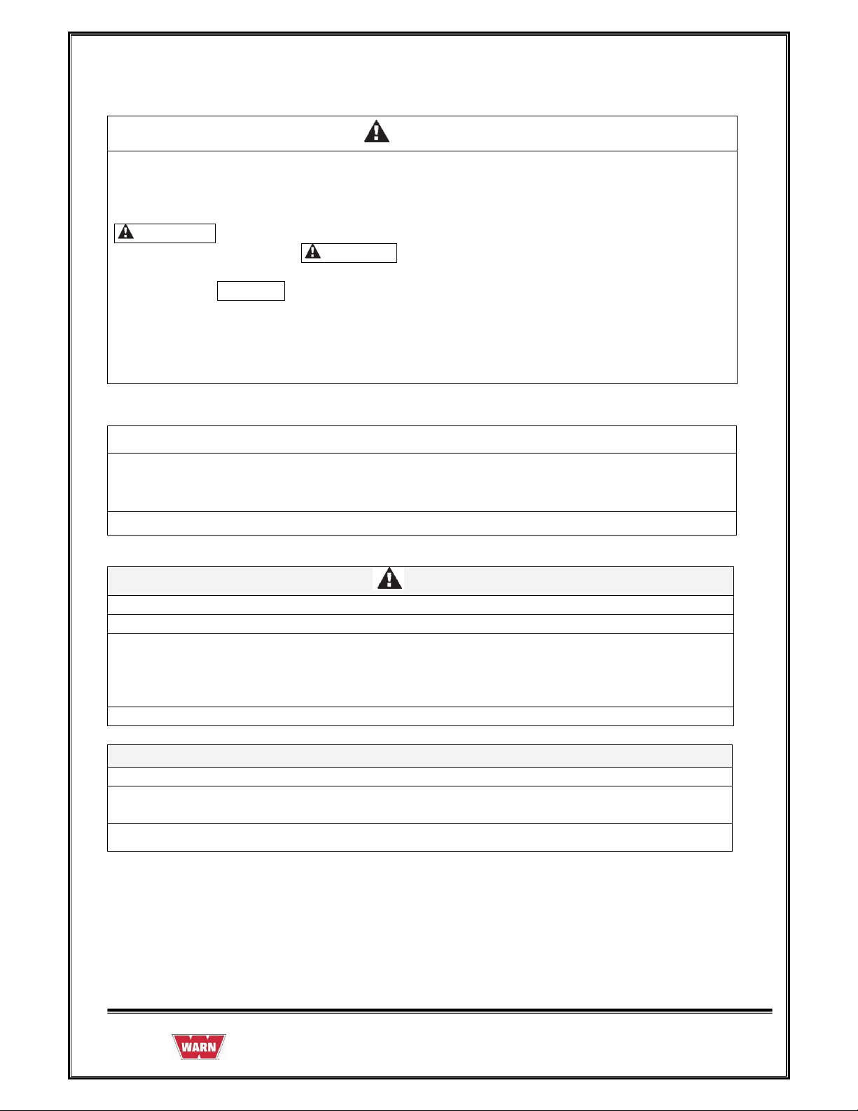
The PullzAll is a powerful, lightweight, easy-to-use handheld electric tool with the ability to
lift or pull up to 1,000 lbs. A strong Motor and Variable Speed Control allow you to move
heavy items into place smoothly and precisely. These features equate to saving both time and
money.
The PullzAll helps in getting the job done easier, faster and with less manual labor than a
come-a-long or chain fall, making you more productive. The PullzAll is for the tradesperson,
farmer/rancher, or anyone that needs to lift or pull up to 1,000 lbs. This makes PullzAll ideal
for construction, pipe fitting, iron work, equipment and plant maintenance, farm and ranch use,
auto shops, garages, machine shops, home improvement, hunting, camping and more.
Cordless PullzAll 24VDC Specifications:
1. Part number 885005 (Domestic US), 885006 (International).
2. Light weight and portable.
3. Powerful 24 Volt rechargeable NiMH Battery pack (with charger and spare Battery)
4. 1,000 lbs. lifting/pulling capacity.
5. 15' of 7/32" diameter Wire Rope.
6. Variable Speed Control for precision load placement.
7. Convenient forward/reverse Switch.
8. Electronic Load Limiter with LED Indicator for operator feedback.
987606A1.doc Page 4 of 46
Page 5
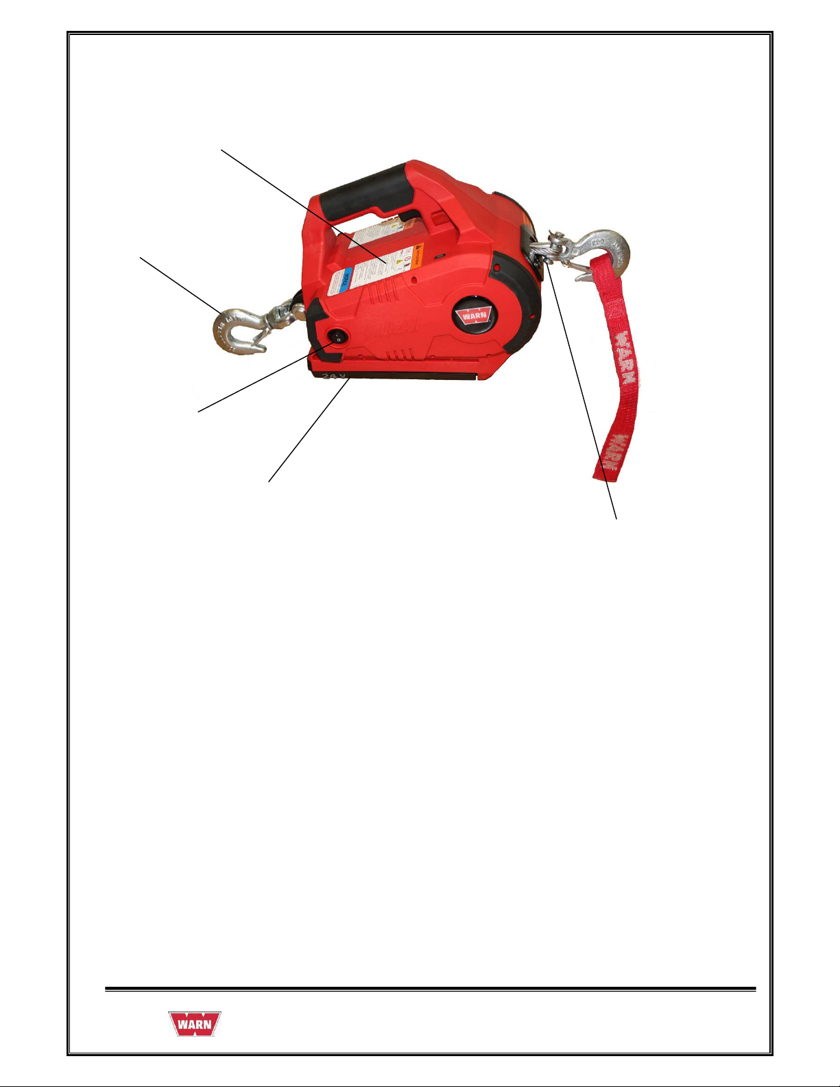
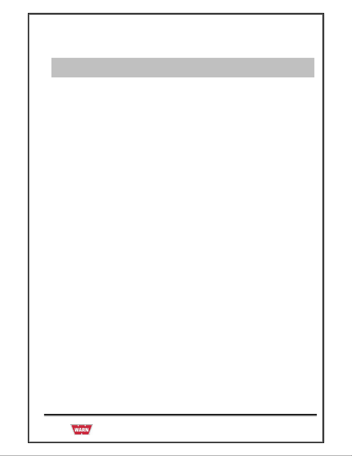
1,000lbs lifting/pulling
Integrated
Swiveling
Anchor
Hook
On/Off Switch
Variable Speed Trigger Switch
Convenient Forward /
Reverse Switch
Electronic Load
Limiter with LED
Indicator for
Operator Feedback
Powerful 24volt Recharge NiMH Battery Pack
15’ of Ø7/32” Wire Rope
987606A1.doc Page 5 of 46
Page 6
2.1 SUGGESTED TOOLS
1. Hammer
2. Snap ring plier
3. Allen key set
4. Screw driver
5. Cutting plier
6. Pin remover (Punch)
7. Insulation tape
8. Gloves
987606A1.doc Page 6 of 46
Page 7

2.2 BATTERY
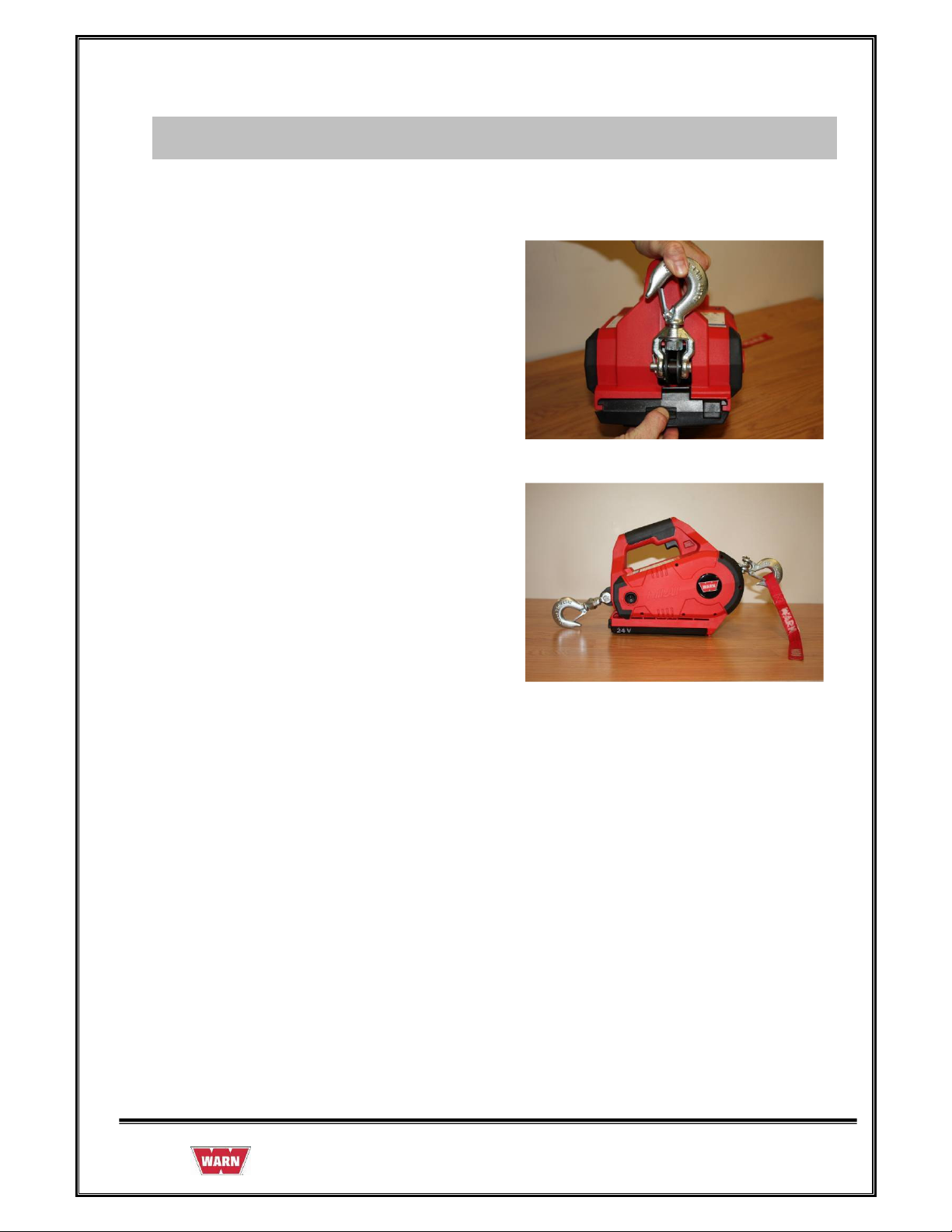
2.2.1 REMOVAL OF BATTERY
Removing the Battery Pack
• Verify the power switch is in the OFF position.
• Push down the release button back of the Battery and slide the Battery away from the
PullzAll body.
• Remove the Battery when not in use. Permanent damage may occur if the unit is
allowed to self-discharge in ON position
987606A1.doc Page 7 of 46
Page 8
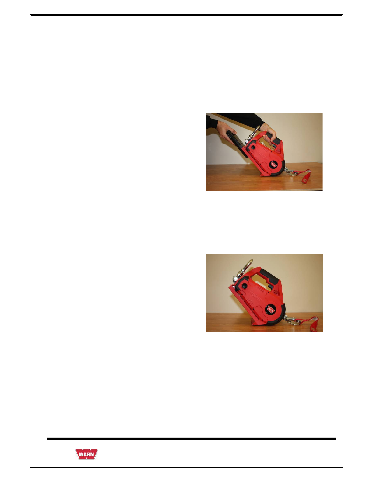
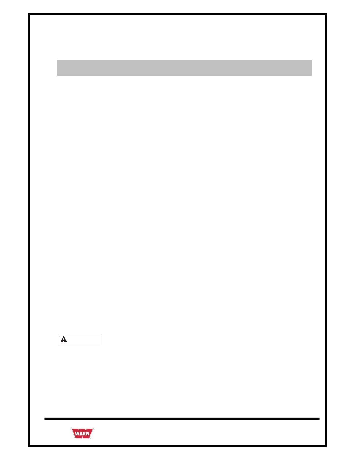
1. Hold the PullzAll in the position shown in
figure, push down the release button at back
of the Battery and slide the Battery away
from the PullzAll body and pull Battery as
shown direction
2. Slide away complete Battery from the
PullzAll body
987606A1.doc Page 8 of 46
Page 9
2.2.2 ASSEMBLY OF BATTERY
1. Hold the PullzAll in the position as shown in
figure. Slide the Battery pack into the body as
shown direction
2. Slide Battery pack completely into the
PullzAll body; make sure that the latch is
fully engaged.
The PullzAll Battery uses NiMH technology. Generally, they can be disposed of in a municipal
waste stream. However, check your local ordinances for disposal or recycling regulations.
987606A1.doc Page 9 of 46
Page 10
2.2.3 INSPECTION OF BATTERY
• Inspect the Battery is not cracked or damaged.
• Inspect whether the release button in hold position or not.
Safety Rules & Guidelines:
• Battery tools are always in an operative condition. Be aware of the possible hazards.
Always remove the Battery when the PullzAllTM is not in use.
• Battery leakage may occur under extreme usage or temperature conditions. If liquid
comes in contact with skin, wash quickly with soap and water, then with lemon juice or
vinegar. If liquid gets into your eyes, flush them with water for a minimum of 10
minutes and seek medical attention.
• Do not run the PullzAll
Battery Care:
When Batteries are not in tool, keep them away from the metal objects. For
example: To protect the terminals from shorting. DONOT place
Batteries in a toolbox or pocket with nails, screws, keys, etc. Fire or injury may result.
DO NOT PUT BATTERY INTO FIRE OR EXPOSURE TO HIGH HEAT. They
may explode.
Battery Disposal:
WARNING
Do not attempt to disassemble the Battery or remove any component projecting from
TM
while carrying it at your side.
the Battery terminals. Fire or injury may result. Prior to disposal protect exposed
terminal with heavy insulating tape to prevent shorting.
987606A1.doc Page 10 of 46
Page 11
2.3 HOUSING
Before opening the Housing follow the below instructions:
Power Switch:
Always turn Power switch off. Permanent battery damage may occur if the unit is allowed to
self discharge in the ON position.
Removing the Battery Pack:
• Verify the power Switch is in the OFF position.
Push down the release Button back of the Battery and slide the Battery away from the PullzAll
body as shown.
987606A1.doc Page 11 of 46
Page 12

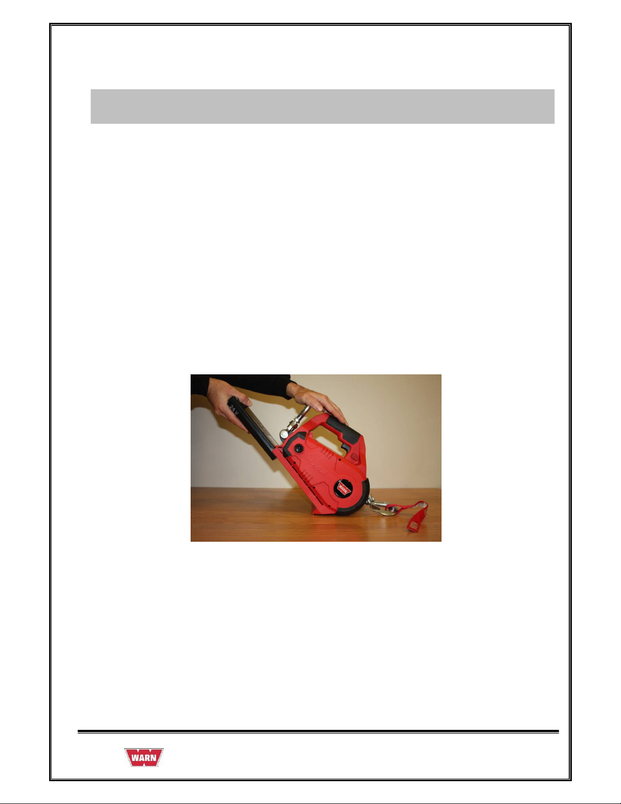
2.3.1 REMOVAL OF HOUSING
1. Remove 6 screws (#6 x .75) from Handle
2. Remove 6 screws (#8 X 1.25) from the
main body of the Housing.
3. Keep the assemblies on the work bench
facing the cover in the direction shown in
the figure.
987606A1.doc Page 12 of 46
Page 13
4. Remove the Plastic Housing (left hand)
from the assembly as shown in the figure.
5. Remove wiring connections of the Motor
assembly from Trigger Switch (red and
black wires) as shown in figure.
6. Remove the Main Chassis from the
Plastic Housing.
7. Keep the Main Chassis on the work
bench.
987606A1.doc Page 13 of 46
Page 14
2.3.2 ASSEMBLY OF HOUSING
1. Keep the right hand Housing on the work
bench
2. Install the Chassis assembly into the right
hand Housing as shown, verify the right
hand frame Bracket is fully seated into
the right Housing before installing the
left hand Housing.
3.Install wiring connections of the Motor
assembly from Trigger Switch (red and black
wires) per wiring diagram (Red to M+ or
M1, Black to M- or M2).
4. Install the Plastic Housing left hand
from the assembly as shown in the figure.
987606A1.doc Page 14 of 46
Page 15

5. Keep the assembly on the work bench
facing the cover in the direction shown in
the figure.
6. Install 6 screws (#8 X 1.25) from the
main body of the Housing.
7. Install 6 screws (#6 x .75) in Handle.
Note: When replacing the Housings with a Housing Service kit, be sure to affix ALL
appropriate labels from the service kit onto the new housings, using the housings
being replaced as a guide for placement of your new labels. Your service kit will
include extra labels for other languages and markets that can be discarded after you
select the ones needed for your product.
987606A1.doc Page 15 of 46
Page 16

2.4 MOTOR
2.4.1 REMOVAL OF MOTOR
Before removing the Motor follow the below instructions:
1. Remove the Motor Assembly from the
End Housing by removing the 2 screws
(M5 x .8 x 12), Qty 2 from the casting
securing the Motor using a 4mm Allen
Wrench.
2. Tap the motor with dead blow hammer to
remove the Motor Assembly remove
from the Chassis assembly.
3. After removal of the Motor assembly
from the Chassis, keep the Motor
assembly on the work bench.
987606A1.doc Page 16 of 46
Page 17

2.4.2 ASSEMBLY OF MOTOR
8. Install the Motor assembly in to the
Chassis assembly.
9. Tighten the two CapScrews to secure
Motor assembly in position.
10. Install Motor leads to top terminals of
Switch per wiring diagram (Red to M+ or
M1, Black to M- or M2).
987606A1.doc Page 17 of 46
Page 18

2.4.3 INSPECTION OF MOTOR
• Visual inspection.
• Ensure that Motor has been properly placed inside the End Housing and the screw had
been properly tightened
2.5 WIRE ROPE ASSEMBLY
2.5.1 REMOVAL OF WIRE ROPE
Note:
Prior to disassembly:
1. Spool out all Wire Rope.
2. Use of gloves is recommended while handling frayed or damaged Wire Rope.
3. Unplug unit / remove Battery before disassembly.
Tasks:
Disassemble the Wire Rope.
1. Push the Wire in the direction of the
arrow mark as shown in the figure.
987606A1.doc Page 18 of 46
Page 19

2. Using a punch or drift and hammer, tap
the end of the Wire Rope to push the loop
back through the Drum.
3. Use the pin remover (punch) to remove
the Wire Rope from the Drum.
4. Remove the Stop Button from Drum
by using snap ring plier as shown in the
figure
987606A1.doc Page 19 of 46
Page 20

5. Straighten the bent Rope and pull the
Rope out of Drum hole in the shown
direction.
6. Remove the hawse fairlead from the
Bracket of the Chassis.
7. Remove and discard the Tension Plate (if
equipped).
987606A1.doc Page 20 of 46
Page 21

2.5.2 ASSEMBLY OF WIRE ROPE
1. Assemble the Hawse Fairlead to the
Bracket of the Chassis.
2. Tighten the CapScrews with Allen key
and opened end wrench.
3. Keep the insulation tape to the edge of the
Wire Rope.
987606A1.doc Page 21 of 46
Page 22

4. Insert the Wire Rope into the Drum
through the Hawse Fairlead.
5. Pull the wire from the other end of the
Drum hole.
6. Bend the Wire Rope and insert in to the
same hole in the direction shown in the
figure.
7. Pull the Wire Rope from the hole as
shown in the figure.
987606A1.doc Page 22 of 46
Page 23

8. Support one edge of the Wire and pull the
other Wire as shown in the figure.
9. Verify Wire Rope stop button is inserted
into the loop as shown before pulling the
Wire Rope tight.
10. Hit wire rope loop with a hammer, so that
the Wire Rope will be pushed in to the
rope retention hole.
987606A1.doc Page 23 of 46
Page 24

11. Check the Wire Rope so that it enters
completely into the Drum hole.
12. Check from the other side of the Drum
whether the Wire Rope is perfectly
assembled to the Drum.
2.5.3 INSPECTION OF WIRE ROPE
• Inspect the Wire Rope for signs of wear or damage. Worn and damaged parts must be
replaced.
• See the Rope for damage for kinks, cuts, knots, mashed or frayed portions and broken
strands.
• Keep the Rope free from contaminants. Use a clean towel to remove the dirt and debris.
• Use of light oil on the Wire Rope can prevent corrosion.
987606A1.doc Page 24 of 46
Page 25

2.6 SAFETY HOOK
2.6.1 REMOVAL OF SAFETY HOOK
To remove Safety Hook, follow the Instructions:
987606A1.doc Page 25 of 46
Page 26

1. First straighten the bent end of the Cotter
Pin by using pliers, and then pull away the
Cotter Pin by holding head of the Pin with
the help of pliers from the Pin.
2. Remove the Pin from the Safety Hook and
Wire Rope.
987606A1.doc Page 26 of 46
Page 27

3. Remove the Safety Hook from Wire Rope.
2.6.2 ASSEMBLY OF SAFETY HOOK
To reassemble Safety Hook follow the Instructions:
1. Place the Safety Hook and align the
mounting holes with the loop of the Wire
Rope
2. Insert the Pin through Safety Hook and
Wire Rope loop.
987606A1.doc Page 27 of 46
Page 28

3. Insert the Cotter Pin inside the hole of the
Pin and bend the ends of the Cotter Pin
with the help of pliers.
2.6.3 INSPECTION OF SAFETY HOOK
• Inspect the Hook for signs of wear and damage.
• Hook damage examples: cracks, twisted components, excessive opening, seat wear,
loose or damaged safety latch or corrosion.
987606A1.doc Page 28 of 46
Page 29

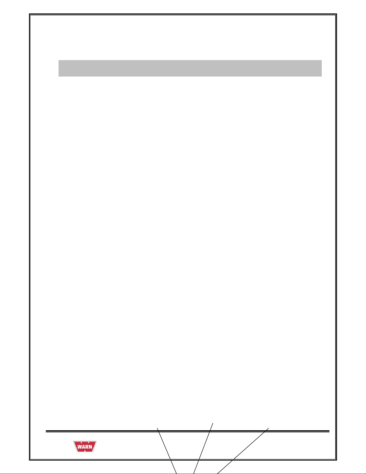
2.7 TAIL HOOK
Original Tailhook Assy
2nd Generation Tailhook Assy
Service Part Tailhook Assy
987606A1.doc Page 29 of 46
Page 30

2.7.1 REMOVAL OF TAIL HOOK
To remove Tail Hook, follow the instructions below:
1. First straighten the bent end of the Cotter
Pin, and then pull out.
2. Remove the Pin from the Hook assembly.
3. Remove the Tail Hook from Chassis
assembly.
987606A1.doc Page 30 of 46
Page 31

4. Remove Spacer Bracket from Chassis
assembly while loosening the capscrew.
2.7.2 ASSEMBLY OF TAIL HOOK
To reassemble Tail Hook follow the instructions:
1. Place Spacer Bracket in Chassis
assembly with capscrew and then apply
the torque.
987606A1.doc Page 31 of 46
Page 32

2. Take the Tail Hook and align the
mounting holes with the Spacer Bracket
holes and Chassis assembly.
3. Insert the Pin through the Hook
assembly.
4. Insert the Cotter Pin inside the hole of the
Pin and bend the ends of the Cotter Pin
with the help of pliers.
987606A1.doc Page 32 of 46
Page 33

2.7.3 INSPECTION OF TAIL HOOK
• Inspect the Hook for signs of wear and damage.
• Hook damage examples: cracks, twisted components, excessive opening, seat wear,
loose or damaged safety latch or corrosion.
987606A1.doc Page 33 of 46
Page 34

2.8 GEARSETS
• If the gearsets are worn or damaged, the entire PullzAll must be replaced, no
replacement parts are available.
2.9 DRUM
• If the drum is worn or damaged, the entire PullzAll must be replaced, no replacement
parts are available.
987606A1.doc Page 34 of 46
Page 35

2.10 WIRING DIAGRAM
WIRING DIAGRAM - 75824
987606A1.doc Page 35 of 46
Page 36

2.10.1 WIRING DETAILS
• Route Red Lead Wire from J3 Terminal on Circuit Board through Wire guides
up into handle to Trigger Switch.
• Route Red Lead Wire (soldered to Male Terminal Support) from J2 Terminal
on Circuit Board through Wire guides up to where the male Terminal support
is mounted.
• Route Black Lead Wire from J4 Terminal on Circuit Board through Wire
guides up to Trigger Switch.
• Route the black lead attached to male terminal support to Rocker Switch.
• Route black lead attached to Black J4 lead at Trigger down through guides
and attach to Rocker Switch.
• Route Motor wires to top of Trigger Switch. Red lead to M+ terminal, black
lead to M - terminal.
• Use tie strap to secure Motor Wires to the right hand frame.
• Secure the Trigger Switch with switch Retainer and a screw. Secure the Wires
in the handle using wire retainer and screws.
• See Wiring diagram 75824 for installation Wiring schematic
987606A1.doc Page 36 of 46
Page 37

Switch Pin-out Table
Manufacturer name is embossed on switch.
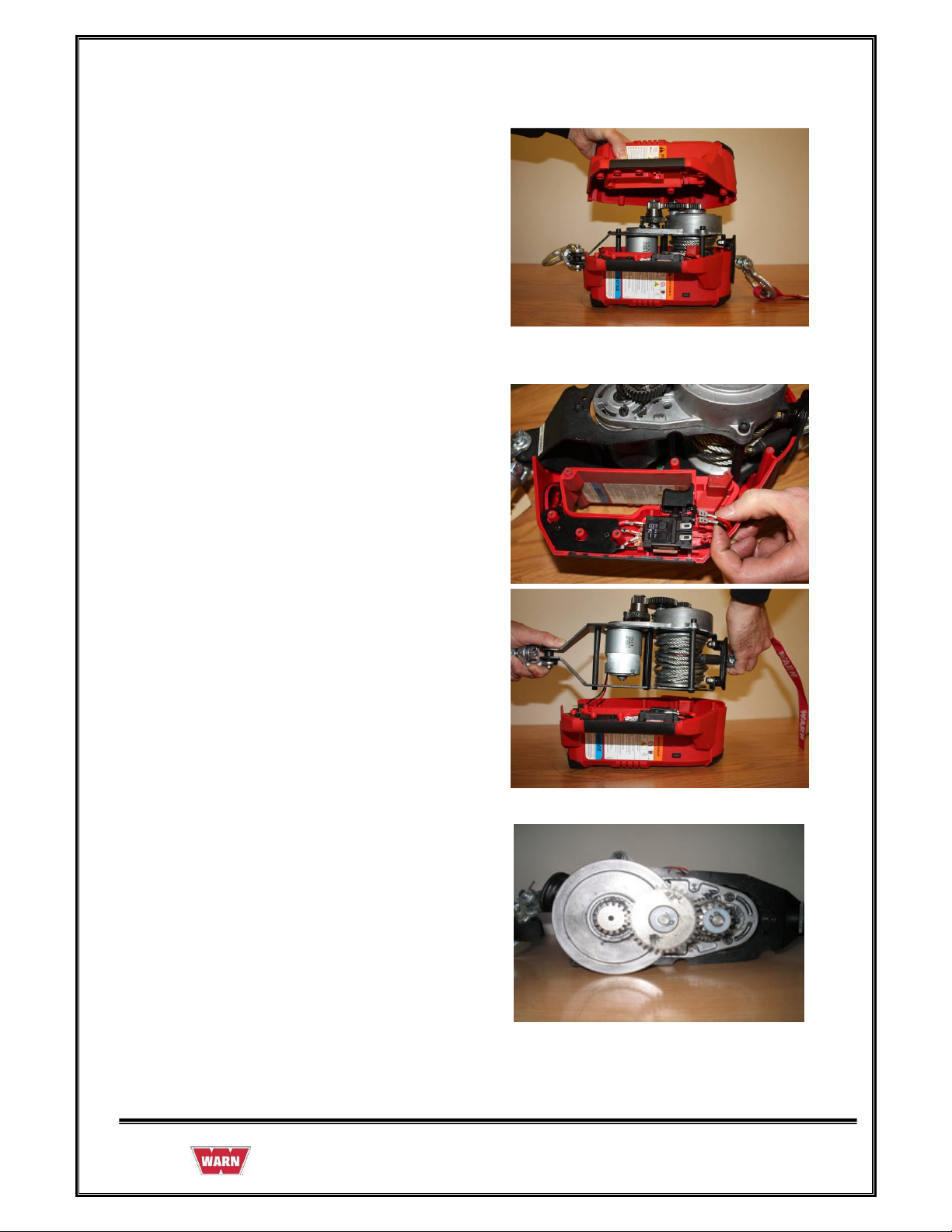
2.10.2 REMOVAL OF WIRING
1. Remove the leads from Battery Terminals if
required.
Trigger Switch:
2. Remove the Wires from Trigger Switch.
987606A1.doc Page 37 of 46
Page 38

3. Remove the leads from Rocker Switch if
required.
4. Take out Load limiter Board Assy from right
Plastic Cover after unscrewing all the screws.
5. Remove the 3 leads from out Load limiter
Board Assy if required.
987606A1.doc Page 38 of 46
Page 39

2.10.3 ASSEMBLY OF WIRING
1. Install Load limiter Board Assy to right
Plastic Cover.
2. Install the two screws at Load limiter
Board Assy with the help screw driver
right Plastic Cover.
987606A1.doc Page 39 of 46
Page 40

Electronic Load Limiter
3. Push the Plastic Retainers out that secure
the LED display
4. Install Battery Terminal into Right Hand
Housing using Screws (6 x 0.50), Qty 2.
987606A1.doc Page 40 of 46
Page 41

5. Route Red Lead Wire (soldered to Male
Terminal Support) from J2 Terminal on
Circuit Board through wire guides up to
rear of Housing to where the Male
Terminal support is mounted.
Trigger Switch
6. Route Red Lead Wire from load limiter
circuit board J3 and black wire from load
limiter J4 through wire guides up in to
handle to Trigger Switch (Red to B+,
Black to B-) Black wire is connected to
black wire from rocker switch.
987606A1.doc Page 41 of 46
Page 42

7. Install leads to Rocker Switch
2.10.4 INSPECTION OF WIRING
VISUAL INSPECTION
• While disconnecting the connectors, never pull the Wiring Harnesses. Unlock the
connector first and then pull them apart by holding Connectors themselves.
• While connecting Connectors, also hold Connectors and put them together until they lock
securely (a click is heard).
• While Installing the Wiring Harness, fix it with clamps so that no slack is left.
• While using a tester for checking continuity or measuring voltage, be sure to insert the
tester probe from the Wire harness side.
987606A1.doc Page 42 of 46
Page 43

2.11 TORQUE SPECIFICATIONS
987606A1.doc Page 43 of 46
Page 44

3. PULLZALL TROUBLE SHOOTING
PROBLEM POSSIBLE CAUSE CORRECTIVE ACTION
1.1 PullzAll does not
power in or pulls
slowly.
Check the speed mode
Battery is not fully charged.
Loose connection on Battery
or Motor Terminals.
selected
Charge Battery
Be sure all connections are tight
and clean. Do not let bottom nut
or stud turn while tightening.
Change mode as required.
Battery voltage too low due
to Battery deterioration.
Worn Trigger Switch
Worn Brushes/Motor.
Poor Wiring Connections.
Check for loaded condition
whether overloaded.
1.2 Noise
Rope is interfacing with Tie
Rod or other part of PullzAll.
Motor is hot.
Abnormally worn Bushing.
Worn or Broken Gearset.
Motor malfunctioning.
Replace Battery.
Repair or Replace Switch.
Replace Motor
Check Wiring connections.
Use the unit within the
permissible load limits.
Rewind Rope on Drum so that it is
level and not rubbing on other
parts of PullzAll.
Allow PullzAll Motor to cool for
at least 10 minutes between short
pulls. Increase cooling time for
heavy loads or long pulls.
Replace PullzAll.
Replace PullzAll
Replace Motor.
987606A1.doc Page 44 of 46
Page 45

1.3 Motor running but
not pulling
1.4 Motor does not run. Check Battery Condition
Damaged Geartrain
visually (any short circuit )
Check Battery condition
Faulty Trigger Switch
Defective Motor
1.6 Electrical sparks
appear around
Motor.
1.7 Wire harness
insulation has melted
Loose connection of Wires to
Motor Terminals.
Switch held in power in
position while PullzAll is
stalled.
Poor installation caused Wire
insulation to be rubbed off or
cut, causing direct short.
Replace PullzAll
Check Wiring condition
Repair or replace it with new
Repair or replace Switch
Replace Motor
Replace Motor Assembly.
Replace Wire harness or PullzAll
Motor Assembly.
Replace Wire harness.
1.8 PullzAll makes
squeaking / high
pitch noise.
1.9 Full speed only, no
variable speed control
1.10 Malfunctioning
1.11 Rapid discharge of
Battery
Drum Bushing not lubricated. Grease Drum Bushings.
Ensure trigger is only
partially depressed
Not operating correctly.
Replace Variable Speed Trigger
switch
Cease operation. Diagnose,
Repair or Replace.
Check for Power Switch Left
on during storage.
Check for Terminals
corrosion
Defects in charging system
such as faulty Regulator,
Always turn unit off when not in
use.
Clean and service
Check charging system
987606A1.doc Page 45 of 46
Page 46

loose Terminals, etc...
Damaged Wiring.
Check Electrical Circuits
4. SERVICE PART LIST
Description Part Number
1. Service Part -Motor Assembly 24vdc 77916
(Includes Motor & Screws)
2. Service Part - Variable Speed Trigger, 24vdc 77913
3. Service Part - Load Limiter Assembly, 24vdc 86355
(Includes LED Bezel, Screws and LED Retention Pins)
4. Service Part - Wire Rope Assembly, PullzAll 76065
(Includes Fairlead)
5. Service Part - Rapid Charger-120v 77922
6. Service Part - Rapid Charger-230v 77923
7. Service Part - Tail Hook Assembly 77930
8. Service Part - Front Hook Assembly 78052
987606A1.doc Page 46 of 46
 Loading...