

Page 1
POWER
PAINTER
PLUS
POWER
PAINTER
MAX
POWER
PAINTER
PRO
™
EZ TILT
powEr paInTEr
Owner’s Manual
Read this manual for complete instructions
®
Français - page 19 / Español - página 37
Contents
2 Important Safety Information
3 Before You Begin
4 Features
5 Cup Mode Setup
6 Remote Suction Hoses Setup
7 Backpack Kit Setup
8 Spray Controls
9 Priming with the Remote Suction Hoses
0312 • Form No. 0525658E
Patent pending
10 Practice Spraying
11 Spraying Technique
12-14 Cleanup
15 Reassembly / Maintenance
16 Troubleshooting
18 Replacement Parts
56 Parts List
60 Warranty
Questions?
Call Wagner Technical Service at:
1-800-328-8251
Register your product online at:
www.wagnerspraytech.com
Proper registration will serve as proof of
purchase in the event your original receipt
becomes misplaced or lost.
Page 2
Important Safety
Grounded Outlet
Grounding Pin
Cover for
grounded
outlet box
SafetySafety
Information
Read all safety information before operating
the equipment. Save these instructions
Indicates a hazardous situation which, if not avoided,
could result in death or serious injury.
a) Toreducetherisksofreorexplosion,electricalshock
and the injury to persons, read and understand all
instructions included in this manual. Be familiar with the
controls and proper usage of the equipment.
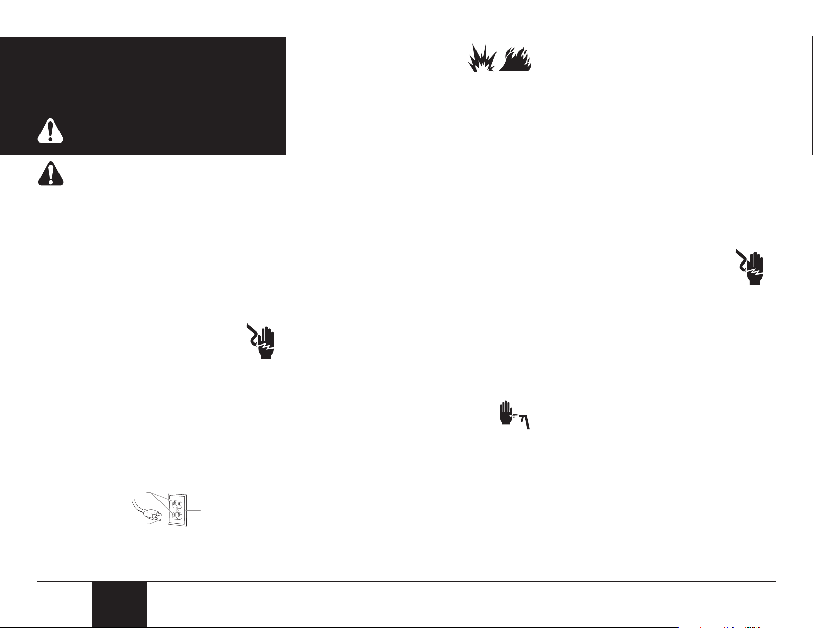
Grounding Instructions
This product must be grounded. In the event of an electrical short
circuit, grounding reduces the risk of electric shock by providing an
escape wire for the electric current. This product is equipped with a
cord having a grounding wire with an appropriate grounding plug.
The plug must be plugged into an outlet that is properly installed and
grounded in accordance with all local codes and ordinances.
WARNING - Improper installation of the grounding
plug can result in a risk of electric shock.
If repair or replacement of the cord or plug is necessary,
do not connect the green grounding wire to either at
blade terminal. The wire with insulation having a green outer surface
with or without yellow stripes is the grounding wire and must be
connected to the grounding pin.
Check with a qualied electrician or serviceman if the grounding
instructions are not completely understood, or if you are in doubt
as to whether the product is properly grounded. Do not modify the
plug provided. If the plug will not t the outlet, have the proper outlet
installed by a qualied electrician.
This product is for use on a nominal 120 volt circuit and has a
grounding plug that looks like the plug illustrated below. Make
sure that the product is connected to an outlet having the same
conguration as the plug. No adapter should be used with this
product.
b)WARNING-Toreducetheriskofre
orexplosion:
1. Do not spray ammable or combustible
materials near an open ame,
pilot lights or sources of ignition such as hot objects,
cigarettes, motors, electrical equipment and electrical
appliances. Avoid creating sparks from connecting and
disconnecting power cords.
2. For use with only water-based or mineral spirit-type
materials with a minimum ash point of 21ºC (70º F) —
Do not spray or clean with liquids having a ash point of
less than 21ºC (70º F). Flash point is the temperature at
which a uid can produce enough vapor to ignite.
3. Verify that all containers and collection systems are
grounded to prevent static discharge.
4. Connect to a grounded outlet and use grounded
extension cords (electric models only). Do not use a 3 to
2 adapter.
5. Do not use a paint or solvent containing halogenated
hydrocarbons. Such as chlorine, bleach mildewcide,
methylene chloride and trichloroethane. They are not
compatible with aluminum. Contact the coating supplier
about compatibility of material with aluminum.
6. Keep spray area well ventilated. Keep a good supply of
fresh air moving through the area to keep the air within
the spray area free from accumulation of ammable
vapors. Keep pump assembly in well ventilated area. Do
not spray pump assembly.
7. Do not smoke in the spray area.
8. Do not operate light switches, engines, or similar spark
producing products in the spray area.
9. Keep area clean and free of paint or solvent containers,
rags, and other ammable materials.
10. Know the contents of the paint and solvents being
sprayed. Read all Material Safety Data Sheets (MSDS)
and container labels provided with the paints and
solvents. Follow the paint and solvent manufacture’s
safety instructions.
11. Fire extinguisher equipment shall be present and working.
c) WARNING - To reduce the risk of skin
injection:
1. Do not aim the gun at, or spray any person or
animal.
2. Keep hands and other body parts away from the
discharge. For example, do not try to stop leaks with any
part of the body.
3. Always use the nozzle tip guard. Do not spray without the
nozzle tip guard in place.
4. Only use a nozzle tip specied by the manufacturer.
5. Use caution when cleaning and changing nozzle tips.
6. High-pressure spray is able to inject toxins into the body
and cause serious bodily injury. In the event that injection
occurs, seek medical attention immediately.
7. This system is capable of producing 2800 PSI / 193
Bar. Only use replacement parts or accessories that
are specied by the manufacturer and that are rated a
minimum of 2800 PSI. This includes spray tips, nozzle
guards and extensions.
8. Verify that all connections are secure before operating the
unit.
d) WARNING - To reduce the risk of injury:
1. Always wear appropriate gloves, eye protection, clothing
and a respirator or mask when painting. Hazardous
vapors – Paints, solvents, insecticides, and other
materials can be harmful if inhaled or come in contact
with body. Vapors can cause severe nausea, fainting or
poisoning.
2. Do not operate or spray near children. Keep children
away from equipment at all times.
3. Do not overreach or stand on an unstable support. Keep
effective footing and balance at all times.
4. Stay alert and watch what you are doing.
5. Do not operate the unit when fatigued or under the
inuence of drugs or alcohol.
e) WARNING - To reduce the risk of electric
shock:
1. Keep electrical cord plug and spray gun
trigger free from paint and other liquids.
Never hold cord at plug connections to support cord.
Failure to observe may result in an electrical shock.
2. Never immerse electrical parts in water or any other
liquid. Wipe the exterior of the sprayer with a damp cloth
for cleaning. Always make sure the sprayer is unplugged
before taking it apart for cleaning.
Important Electrical Information
IMPORTANT: Useonlya3-wireextensioncordthathas
a 3-blade grounding plug and a 3-slot receptacle that will
accepttheplugontheproduct.Makesureyourextension
cordisingoodcondition.Whenusinganextensioncord,
be sure to use one heavy enough to carry the current your
product will draw. For lengths less than 50 feet, use a No.
18AWGextensioncord.Forlengthsmorethan50feet,use
aNo.14orNo.16AWGextensioncord.Anundersized
cord will cause a drop in line voltage resulting in loss of
power and overheating.
Wagner Spray Tech accessory extension cords recommended:
P/N 0090241 20 foot extension cord
P/N 0090242 35 foot extension cord
2
English
Page 3

SafetySafety
Before you begin:
This page contains information that is
necessary in order to operate the sprayer
properly.
Material Preparation:
• It is important to mix the material thoroughly before you
begin. Do not shake the material to mix it. Always stir
the material gently but thoroughly before use.
• Remove any skin that has formed on the top of the
material. Do not mix the skin into the material. The
skin can break up and clog the sprayer. Older paint
may need to be strained.
Thinning the Material:
• Always test spraying without thinning the material as
thinning is not typically required.
• If you are spraying with a material that needs to
be thinned, make sure to follow the manufacturer’s
recommendations.
Material That Can Be Sprayed:
• Make sure the type of paint you use can be cleaned
with either mineral spirits (for oil-based paints) or a
warm water and soap solution (for latex paints).
Determining Job Size:
The size of your spray job will determine how the spray
gun is set up. The spray gun can operate in three
different modes:
1) cup mode for small to medium jobs (see page 5)
2) remote suction hose mode for medium to large jobs (if
equipped, see page 6)
3) backpack mode for large jobs that require increased
mobility (if equipped, see page 7)
Overspray:
Some sprayed materials create a cloud of paint. Some
of that cloud will spray past your intended object and
also bounce off of it. Wind and air currents may cause
this cloud to drift onto surfaces not intended to be
sprayed. You can control the amount of overspray
and bounce-back by adjusting your spray controls and
moving the sprayer closer to the work piece, but always
make sure that you have a good spray pattern. Always
test your pattern on a scrap piece of wood or cardboard,
and make sure that you have drop cloths protecting
anything not being sprayed.
Anything you don’t want painted that is in the area
of your spraying surface should be covered or
removed.
Drop Cloths:
Be sure to protect your oors and furnishings with drop
cloths or other coverings during spraying and cleanup.
Spray Tip:
The spray tip included with your Power Painter comes
equipped with Optimus™ dual-orice technology. It
is ideal for spraying both water-based and oil-based
paints and stains. The Optimus™ spray tip eliminates
the need to have different spray tips for different spray
materials.
Capability:
Sprays a variety of paints (oil-based and latex), primers,
stains, preservatives and other nonabrasive materials. Do
not use materials with ash points below 70° F (21° C).
Do not use!
This pump should not be used with textured materials,
block ller, lacquers, industrial enamels, or asphalt
sealer or materials containing HHC. See coating
supplier if ash point is not listed on the container.
3
English
Page 4
o
a
a1
a2
b
e
d
l
n
m
p
a1
a2
a
Power Painter
Max
Power Painter
Plus
Power Painter
Pro
c
d
g
g
h
h
j-k i-k
f
a
a1
a2
g
f
d
c
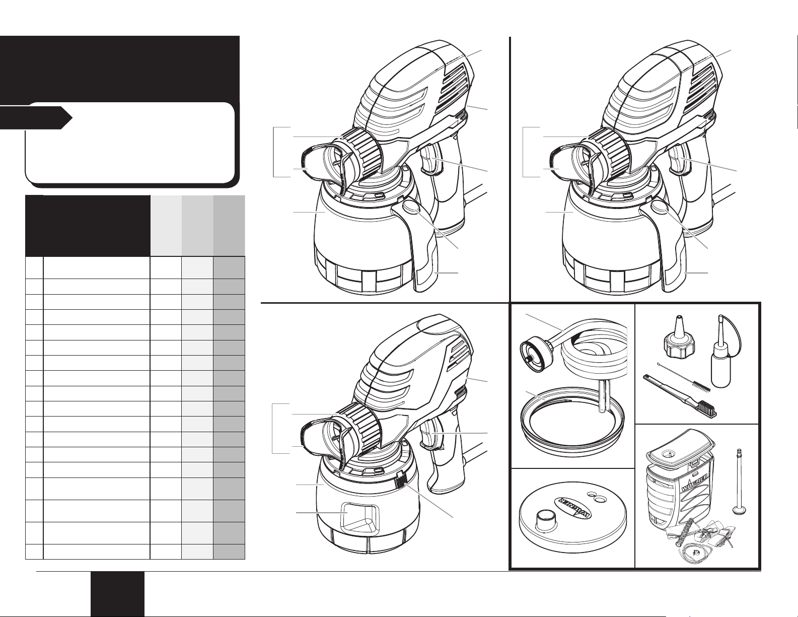
Features
Start
The spray gun you have purchased will
have some or all of the features and
accessories shown here. Refer to the
graphic, right, and the chart, below.
Features
Adjustable spray tip
a
assembly
Tip nut
a1
Spray adjustment guard
a2
1 quart cup
b
1 1/2 quart cup
c
Cup release button
d
Cup grip
e
Cup handle
f
Trigger
g
Material select lever
h
Electronic material selector
i
Electronic speed control
j
Low cup level indicator
k
Remote suction hose kit
l
Fill lid adapter (for threaded
m
containers)
Fill lid (standard
n
containers)
Cleaning brushes, cleaner
o
nozzle and lubricant
Backpack kit
p
4
Notice:
English
Power
Painter Plus
Power
Painter Max
h h h
h h h
h h h
h
h h h
h
h h h
h h
h h h
h h h
h h
h h
h h
h h
h h
h h
Power
Painter Pro
h
h
Page 5
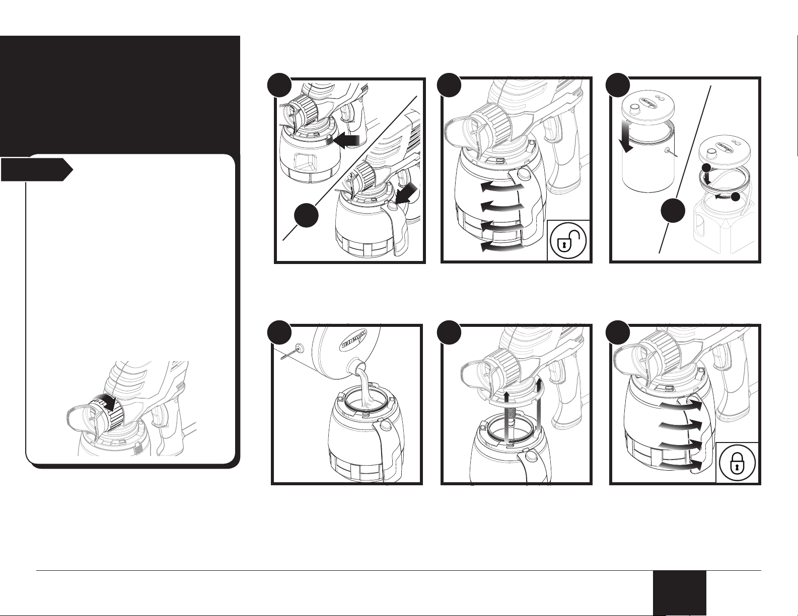
Cup Mode Setup
Start
Note: The cup will give you approximately 3-5
minutes of continuous spraying time depending
upon the cup size.
IMPORTANT: Avoid running the cup dry.
An empty cup will allow air to become
sucked into the sprayer, which leads to
globbing and spitting.
Note: Some of the graphics in this manual
may not exactly match your sprayer. All
information and instructions given in this
manual applies to all models except where
noted.
IMPORTANT: Always make sure the tip nut
is tightened securely prior to spraying.
Recommended for
small to medium jobs
1
or
1. Remove the cup Press and hold cup release
button.
4
2
2. Turn cup to release.
Remove cup.
5
3
2
1
or
3. Attach ll lid to the paint
container for easier pouring.
6
4. Fill the cup.
Note: Fill right up to, but do not
exceed, the MAX FILL line.
5
5. Replace the cup Line up the tabs / slots.
Note: The cup grip / cup handle
can be oriented on either side of
the sprayer, depending upon your
preference.
6. Turn cup to lock.
Note: The cup should “click” back
into place.
English
English
Page 6
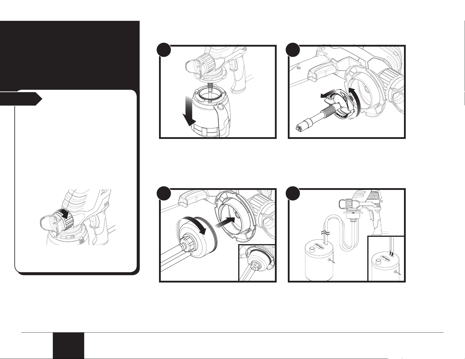
Remote Suction Hose Setup
(optional)
Start
Note: A 75% duty cycle is recommended when
spraying with the remote suction hoses. For
example, trigger the gun for 15 seconds, and
then allow the gun to remain idle (untriggered)
for 5 seconds.
IMPORTANT: Avoid running the container
dry. An empty container will allow air to
get sucked into the sprayer, which leads to
globbing and spitting.
IMPORTANT: Always make sure the tip nut
is tightened securely prior to spraying.
Recommended for
medium to large jobs
1
1. Remove the cup See steps 1-3, previous page.
3
2
2. Twist and remove the suction tube and
lter assembly.
4
Note: The Low Cup Level Indicator (if
equipped, see page 8) are not applicable when
using the remote suction hoses.
3. Attach the housing to the bottom of the
sprayer as shown.
Rotate the housing until it clicks into place.
6
English
4. Attach lid to paint container.
Push hoses through the holes in the lid
and down to the bottom of the material
container.
Page 7
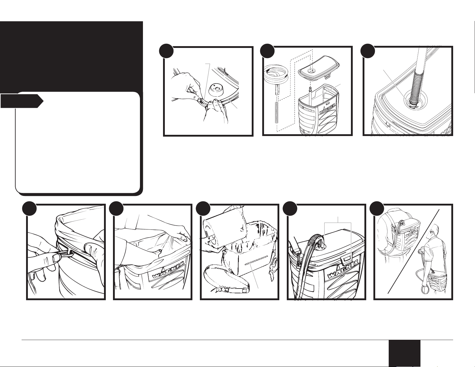
Backpack Kit
(a)
(b)
(e)
(f)
(c)
(d)
Setup
(optional)
Start
Note: A 75% duty cycle is recommended when
spraying with the backpack kit. For example,
trigger the gun for 15 seconds, and then allow
the gun to remain idle (untriggered) for 5
seconds.
IMPORTANT: Avoid running the backpack
dry. An empty backpack will allow air to
get sucked into the sprayer, which leads to
globbing and spitting.
IMPORTANT: Always make sure the tip nut
is tightened securely prior to spraying.
4 5
Recommended for
medium to large jobs
1
1. Lay cord seal (a) in backpack
lid groove (b). Overlap the
ends of the cord seal by
approximately 1/2 inch. Cut off
remaining seal.
Lift seal and butt edges
together and press excess seal
into groove.
6
2
2. Snap backpack suction tube
(c) through hole in bottom of
backpack lid.
Assemble backpack kit as
shown.
7 8
3
3. Secure clip onto suction tube (d).
When backpack kit is
assembled, follow steps 1-5 in
Remote Suction Hose Setup
(previous page) to attach the kit
to the sprayer.
4. Assemble strap hooks to
container using same hole
as lid clip. Adjust strap to
t user.
7
5. If you want to use a
backpack liner, install as
shown.
6. Pour material into
backpack to ll line. Do
not ll above the indicated
ll line (e).
7. Place lid on backpack and
press rmly into place.
Secure with the tabs (f).
8. Backpack can either be
back- or shoulder-mounted
as shown. Adjust straps to
t user.
English
Page 8

PAINT STAIN
Power Painter Max
LOW
LEVEL
SPEED
HOLD TO RESET LOW LEVEL
a
b
c
c
a
d
b
e
f
Power Painter Pro
Spray Controls
Start
The spray controls vary depending upon the model of
sprayer you have. Refer to this page in order to learn
about the controls of your particular sprayer.
Material Select Lever:
The spray pattern is controlled by the Material Select Lever
on the rear of the sprayer, and by the thickness of the
material being sprayed.
If you are spraying thicker materials such as latex paint, turn
the lever toward the “PAINT” side of the sprayer.
If you are spraying thinner materials such as thinner stains,
turn the lever toward the “STAIN” side of the sprayer.
Note: If you are unable to acheive a good spray pattern
while using the ‘STAIN’ setting, switch the lever over to
‘PAINT’.
Notice:
Power Painter Plus
Material Select Lever:
Refer to the information given in the previous column.
Electronic Speed Control:
The electronic speed control is displayed by the two
green lights on the right side of the control panel (a).
The Power Painter Max offers two speed levels (LO /
HI). The lower the speed level, the closer you can get to
your work and the less overspray you will have.
Lower speed levels give you greater control but require
more time to cover an area. Depending upon the
thickness of the material or conditions, the settings may
need to be adjusted.
To adjust the speed setting, press the ‘SPEED’ button
(b) below the speed indicator lights until your desired
speed is reached.
Low Cup Level Indicator
• Applicable only when spraying in cup mode, cup
lled to MAX FILL.
• The low cup level indicator is displayed by the two
red lights on the left of the control panel (c).
When your cup is running out of material, the low cup
level indicators will begin blinking. You should quit
spraying and rell the container (see Cup Mode Setup
instructions, page 5). Avoid running the cup dry. An
empty cup will allow air to become sucked into the
sprayer, which leads to globbing and spitting.
Note: Before you resume spraying, press and hold the
‘SPEED’ button (b) and the indicators will reset and no
longer blink. ALWAYS reset the indicators when the cup
is full and you are ready to resume spraying. Failure
to reset the low cup level indicators will result in the
indicators not functioning properly. The low cup level
lights will reset whenever the power cord is unplugged.
Electronic Material Selector:
The spray pattern is controlled by the Electronic Material
Selector (a) and by the thickness of the material.
If you are spraying thicker materials such as latex paint,
press the ‘SELECT’ button (b) until the indicator light
indicates ‘PAINT’.
If you are spraying thinner materials such as thinner stains,
press the ‘SELECT’ button (b) until the indicator light
indicates ‘STAIN’.
Electronic Speed Control:
The speed control is displayed by the three green lights on
the upper right side of the control panel (c).
The Power Painter Pro offers three speed levels (LOW/
MED/HIGH). The lower the speed level, the closer you can
get to your work and the less overspray you will have.
Lower speed levels give you greater control but require more
time to cover an area. Depending upon the thickness of the
material or conditions, the settings may need to be adjusted.
To adjust the speed setting, press the ‘SPEED’ button
(d) until your desired speed is reached. If the sprayer is
unplugged, the current speed and electronic material selector
setting will be “stored” and remembered during restart.
Low Cup Level Indicator
• Applicable only when spraying in cup mode, cup lled
to MAX FILL.
• The low cup level indicator is displayed by the two red
lights on the bottom right of the control panel (e).
When your cup is running out of material, the low cup level
indicators will begin blinking. You should quit spraying and
rell the container (see Cup Mode Setup instructions, page
5). Avoid running the cup dry. An empty cup will allow
air to become sucked into the sprayer, which leads to
globbing and spitting.
Note: Before you resume spraying, press and hold the
‘RESET’ button (f) and the indicators will reset and no
longer blink. ALWAYS reset the indicators when the cup
is full and you are ready to resume spraying. Failure to
reset the low cup level indicators will result in the indicators
not functioning properly. The low cup level lights will reset
whenever the power cord is unplugged.
8
English
Page 9

Priming with
PAINT
the Remote
Suction Hoses
Start
Follow these steps if you plan to spray
while using the remote suction hoses or
the backpack kit.
Notes:
• The time needed to prime will vary from
• If your sprayer is properly cleaned and
• Using the remote suction hoses will
• A 75% duty cycle is recommended
IMPORTANT: Always make sure the tip nut
is tightened securely prior to spraying.
Notice:
30 seconds to 3 minutes depending upon
the thickness of the material you are
spraying.
oiled and it takes longer than three
minutes to prime, your piston and/or pump
housing may be worn and will need to be
replaced before using your remote suction
set.
decrease the material ow, so it will
take longer to apply the same amount of
material to the surface being sprayed.
when using the remote suction set. For
example, trigger the gun for 15 seconds,
and then allow the gun to remain idle
(untriggered) for 5 seconds.
1a
1b 2
or
1a. If equipped Turn the material select lever to
‘PAINT’.
1b. If equipped -
Press the ‘SELECT’ switch until
the light indicates ‘PAINT’.
3
3. Aim the sprayer at a piece of scrap wood or
cardboard.
Squeeze the trigger and hold until all air is out
of the system and material is owing freely out
of the sprayer tip. This could take up to three
minutes.
2. Hold the sprayer even with
the level of the paint. This will
speed up the priming.
IMPORTANT: The suction hose must remain
completely submerged in the material. If it is
not completely submerged and air is sucked
into the system, the piston could seize.
If the piston seizes, the sound the gun makes
will change to a low hum and the gun will
quickly become hot to the touch. Never run the
sprayer when the piston is seized.
Should this happen, clean the piston and the
pump housing thoroughly using the cleanup
procedures found in this manual.
9
English
Page 10

Safety
PAINT STAIN
a)
b)
PAINT
LO W
LEVEL
SPEED
HOLD TO RESET LOW LEVEL
LO W
LEVEL
SPEED
HOLD TO RESET LOW LEVEL
Practice Spraying
Start
Start
• a scrap piece of wood or cardboard
Important - read before spraying
Priming the Sprayer
Once you are ready to spray, it may take 20
seconds for material to spray after you pull the
trigger.
The sprayer may sound choppy, while at the
same time spit or spray large globs briey prior
to the spray coming out in a ne mist. This is
normal.
Keep holding the trigger and material will come
from the sprayer in a ne mist.
Overspray
Some sprayed materials create a cloud of paint.
Some of that cloud will spray past your intended
object and also bounce off of it. Wind and
air currents may cause this cloud to drift onto
surfaces not intended to be sprayed. You can
control the amount of overspray and bounceback by adjusting your material select control
and moving the sprayer closer to the work
piece, but always make sure that you have a
good spray pattern. Always test your pattern
on a scrap piece of wood or cardboard, and
make sure that you have drop cloths protecting
anything not being sprayed.
Anything you don’t want painted that is in
the area of your spraying surface should be
covered or removed.
You will need:
1
or or
1. Turn the material select lever
toward “PAINT”, or. . .
Press the ‘SELECT’ switch
until the light indicates ‘PAINT’.
Note: The “PAINT” setting will
allow the sprayer to prime faster.
4
4. If equipped Adjust the material select lever
as needed to achieve a good
spray pattern.
2
2. If equipped Set the speed control to the
highest setting.
5
5. If equipped Adjust the material selector
and speed control as needed
to achieve the desired spray
pattern.
3
3. Point the sprayer at a
scrap piece of wood or
cardboard, and pull the trigger
(approximately 10 seconds)
until material sprays evenly
from the spray gun.
6
6. (a) - Bad spray pattern.
(b) - Good spray pattern.
10
English
Page 11

Spraying
Keep stroke
even
End
stroke
Start
stroke
Pull
trigger
Release
trigger
Move steadily
* Slower speeds (if equipped) will allow to you get closer to the spray surface.
Aproximately
10 to 14 inches*
Technique
1
2
Start
Start
Adjusting the spray
tip assembly:
The adjustable spray tip assembly produces
a pattern that can be adjusted horizontally or
vertically. Rotate the spray adjustment guard
(b) as shown.
Spraying horizontally (side to side):
b
a
Spraying vertically (up and down):
a
b
1. Keep your arm moving at constant speed and keep the
sprayer at a constant distance from the surface. The
sprayer should be triggered at the beginning of the stroke
and released at the end of the stroke.
IMPORTANT:
If a large amount of material is leaking from behind the adjustable spray tip assenbly, turn
off the sprayer immediately or the sprayer could be damaged. The sprayer will leak from
behind the adjustable spray tip assembly if the tip nut is not tightened firmly. If you notice
material leaking from this area, follow the steps below.
2. Keep the sprayer at a consistent distance to the
surface. This means moving your entire arm back
and forth rather than just exing your wrist. Overlap
each stroke by 50%.
1 2 3
a
b
To prevent an injection hazard,
make sure the sprayer is unplugged
before you adjust the spray tip.
Make sure the spray tip nut (a) is
sufcientlyhandtightenedpriorto
spraying.
11
1. Unplug the sprayer
immediately.
Remove the adjustable spray tip
assembly.
Note: Remove the adjustable spray
tip assembly by turning the spray
tip nut (a), not the spray adjustment
guard (b).
2. Remove the atomizer valve and
see if it needs to be cleaned or
replaced (see page 18).
Also check the pump housing
opening for any dirt or other
obstruction and clean if
necessary.
3. Put the atomizer valve back
in place, making sure it can
seat properly without any
obstruction.
Thread on the adjustable spray
tip assembly by turning the
tip nut clockwise and tighten
rmly by hand.
English
Page 12

Cleanup
(a)
(cup mode)
Start
• Waste container
• Cleaner nozzle and lubricant
• Warm soapy water if you sprayed latex
• Mineral spirits if you sprayed oil-based
You will need:
materials
materials
Make sure you clean the sprayer in a
well-ventilated area whenever
cleaning with flammable solvents.
The sprayer contains electrical parts.
DO NOT submerge the sprayer into
any liquids.
1
1. Unplug the sprayer. Pour the
remaining material back into
the original container.
Rinse the inside of the cup
with the appropriate cleaning
solution.
54
2
2. Remove the suction tube and
lter assembly.
6
3
3. Disassemble the suction tube
and lter assembly.
Note: The threads on the bottom
housing (a) are left-handed. You
will need to turn the bottom housing
to the right in order to remove it.
7
4. Turn the tip nut counterclockwise and remove the
adjustable spray tip assembly.
Pull the atomizer valve out,
being careful not to lose it.
12
English
5. Turn the locking nut
counterclockwise until it is
removed.
6. Slide the pump housing off the
sprayer.
7. Remove the spring and piston
from the pump assembly.
Page 13

(a)
(a)
(b)
8 9 10
8. Clean all parts thoroughly with
the brush provided using a
solution appropriate to the type of
material you sprayed.
LATEX MATERIALS ONLY OIL-BASED MATERIALS ONLY
11. Thread the cleaner nozzle onto
a garden hose.
9. IMPORTANT: Make sure to completely
remove all material from the inside of the
piston chamber by scrubbing with the
brush. Even a small amount of material
can dry like glue and keep the piston from
moving, causing damage to the sprayer.
1211
12. Insert nozzle into the end of
the suction tube and place into
a waste container.
Turn on the water and ush
the suction tube until clean.
10. IMPORTANT: Make sure to keep the vent
hole (a) on the pump housing clean and
unblocked or a vacuum can build up in
the container and cause damage to the
sprayer. A toothpick or straightened paper
clip can be used to clean it.
13 14
13. Using the cleaning brush and
mineral spirits, clean out the
inside of the suction tube.
14. Lubricate the O-rings as
Reassemble the lter
shown with the included
lubricant.
assembly.
13
English
Page 14

Cleanup
(remote suction
hoses / backpack kit)
Start
• Waste container
• Cleaner nozzle
• Warm soapy water if you sprayed latex
• Mineral spirits if you sprayed oil-based
You will need:
materials
materials
Make sure you clean the sprayer in a
well-ventilated area whenever
cleaning with flammable solvents.
The sprayer contains electrical parts.
DO NOT submerge the sprayer into
any liquids.
1 2 3
1. Unplug the sprayer.
Remove the remote suction set from the
material container / backpack assembly
and submerge into a container of the
solvent appropriate to the type of material
you sprayed.
LATEX MATERIALS ONLY
2. Plug in the sprayer.
Squeeze the trigger and
spray into a waste container
until the cleaning solution
comes through the sprayer
for a couple of minutes.
5 764
3. Unplug the sprayer.
Remove the remote suction
set housing from the sprayer.
Remove smaller return hose
from suction set housing.
Note: If you used the
backpack kit, be sure
4. Disassemble the remote suction set
housing.
Clean all parts by hand using the
cleaning brush and the appropriate
cleaning solution.
Reassemble.
14
English
to clean the suction
tube and the inside of
the backpack by hand
using the appropriate
cleaning solution.
5. Thread the cleaner
nozzle onto a garden
hose.
6. Insert nozzle into one of
the remote suction hoses.
Place the other end of
the hose into a waste
container.
Turn on the water and
ush the hose until clean.
Repeat for the other
hose.
7. Reattach the smaller
return hose to the dual
hose tting.
Follow steps 4-10 in
Cleanup - Cup Mode
(page 12).
Page 15

Reassembly /
(a) (b)
(c)
Maintenance
Start
• Scrap piece of wood or cardboard
• Lubricant
Note:PowerPainterMaxonly - Refer to page
58 to see the proper way to repack the sprayer
and components ito the carrying case.
You will need:
1
1. Slide the spring onto the front
end of the piston.
Insert the piston into the back
of the pump housing.
54
2
2. Insert the pump housing
assembly into the front of the
sprayer.
6
3
3. Place the locking nut onto
the pump housing. Press in
while turning the locking nut
clockwise.
Do not cross-thread the
locking nut. Make certain it
is threaded correctly before
tightening.
7
4. Insert the atomizer valve into the
front end of the pump housing.
Place the adjustable spray tip
assembly onto the pump housing
and turn the tip nut clockwise
15
until it is tightened securely.
5. Turn the sprayer upside-down
while the cup is removed.
Squeeze a small amount of
lubricant into both the intake
(a) and return (b) openings on
the pump housing.
6. Plug in the sprayer. Aim
at piece of scrap wood or
cardboard and squeeze the
trigger of the sprayer for 2 to
3 seconds while sprayer is still
inverted.
7. Reassemble and reattach
the lter and suction tube
assembly.
Lubricate the O-ring (c) as
shown with the included
lubricant. Replace the cup.
English
Page 16

Any attempt to open the motor housing or repair any electrical parts
within the unit by anyone other than an authorized repair technician
Troubleshooting
could cause serious injury and will void the warranty.
Problem A: Motor will not run
Cause Solution
1.
No power at wall outlet. Electrical problem or defective
motor.
Try new wall outlet. Take to Authorized Service Center for repair.
Problem B: Motor has a low hum and does not spray
Cause Solution
1.
Seized piston Disassemble sprayer, clean and lubricate (follow Cleanup, Cup Mode instructions)
Problem C: Motor operates properly but does not spray
Cause Solution
1. Failure to prime with remote suction set
2. Failure to prime with suction tube
3. Loose or damaged suction tube Tighten or replace
4. Plugged or worn atomizer valve Clean or replace as needed
5. Atomizer valve missing Replace atomizer valve
6. Material selector needs adjusting Adjust to “PAINT” setting.
7. Speed setting too low Increase the speed setting (if equipped)
8. Plugged spray tip Clean tip
9. Filter assembly plugged Clean lter assembly
10. Material too thick Thin material
11. Worn piston Clean and oil, or replace
Oil intake opening (see Reassembly / Maintenance section). Hold trigger for at least 3 minutes. Thin
paint. Hold sprayer at even level with paint can.
Oil intake opening (see Reassembly / Maintenance section). Hold trigger for at least 20 seconds. Thin
paint.
Problem D: Material spitting or globbing (air has entered the system)
Cause Solution
1. Low on paint Rell container
2. Worm atomizer valve Replace atomizer valve
3. Plugged spray tip
4. Material selector needs adjusting Adjust to “PAINT” setting.
5. Speed setting too low Increase the speed setting (if equipped)
6. Worn piston Clean and oil, or replace
7. O-rings on lter assembly are dirty
8. Material too thick Thin material
16
English
Clean the spray tip (follow Cleanup, Cup Mode instructions)
Clean and lubricate (follow Cleanup, Cup Mode instructions)
Page 17

Troubleshooting
Problem E: Excessive fogging
Cause Solution
1.
Material selector set too high Set material selector to ‘STAIN’
2.
Holding sprayer too far from work surface Hold sprayer closer to work surface
Problem F: Runs and sags in paint
Cause Solution
1.
Arm movement too slow, holding spray gun too close or work
surface, or applying too much paint at one time
Problem G: Material drips from spray tip or guard
Cause Solution
1.
Guard is for safety and cannot be removed. Some dripping is
unavoidable with some paints
Problem H: Material leaking from between spray tip and locking nut.
Cause Solution
1. Spray tip is loose Tighten securely
2. Atomizer valve not positioned properly Unplug the sprayer, remove the spray tip and reposition the atomizer valve
3. Worn atomizer valve Replace
4. Eroded pump housing Replace the pump housing
See section on spraying (page 8)
Use a small brush on drips that fall on surface being sprayed. Use a drop cloth
Problem I: Motor overheats
Cause Solution
1. Seized piston Clean piston
2. Extension cord too long Replace with proper size
3. Operating continuously Release trigger at the end of a pass, allow to cool.
Have you tried the recommendations above and are still having problems? In the
United States, to speak to a customer service representative, call our Customer Service
at 1-800-328-8251 Monday through Friday between 8:00 AM and 4:30 PM Central time.
This unit has no servicable electrical parts.
Do not attempt to service this unit yourself.
17
Questions?
Call Wagner Technical Service at:
1-800-328-8251
Register your product online at:
www.wagnerspraytech.com
Proper registration will serve as proof of
purchase in the event your original receipt
becomes misplaced or lost.
English
Page 18

Replacement
1
1
2 3
Front view of a good atomizer valve.
2
Front view of a atomizer valve after spraying 7-10 gallons
of latex paint. Replace.
3
Front view of a atomizer valve after spraying 7-10 gallons
of latex stain. Replace.
parts
Atomizer valve:
The atomizer valve is shaped to cause the material to spin as it comes out
of the sprayer. The spinning breaks the material up into a ne spray. As
more material goes through the atomizer valve, it wears out the valve and
the shape of the valve changes. When it changes too much to produce a
good spray pattern, the valve needs to be replaced.
Start
Parts of your sprayer wear out with use and
require regular replacement. They include
the atomizer valve, piston and spring. These
parts are not covered by your sprayer
warranty.
Moreabrasivematerialssuchaslatexpaints
and stains cause these parts to wear out
faster than less abrasive materials such as
oil-based paints and stains, thin stains and
sealers.
Notice:
Piston and Spring:
The average life of a piston and spring will vary depending on the types of
material being sprayed.
Replace the piston if the sprayer takes longer than 20 seconds with the
suction tube to prime when well lubricated, or if there is an excess amount
of material leaking, refer to the troubleshooting suggestions listed in this
manual. Replace the spring if you notice that it is broken when you clean
the sprayer.
To replace either the atomizer valve or the piston and spring, follow
the Cleanup instructions on page 12-13, and replace the old parts with
new ones. When replaced, follow Reassembly instructions, (page 15).
18
English
Page 19

(o)
(n)
(q)
(j)
(s)
(a)
(i)
(k)
(l)
(m)
(p)
(d)
(e)
(f)
(g)
(h)
(*)
(*)
(*)
(*)
(*)
(r1)
(r2)
(c)
(b)
(*)
(*)
(q1)
Parts List • Liste de pièces • Lista de piezas
56
English Français Español
Page 20

Parts List • Liste de pièces • Lista de piezas
Item
Article
Articulo
a) ---------- Sprayer assembly Pulvérisateur Rociador 1
b) 0199903 Piston Piston Émbolo 1
c) 0016101 Spring Ressort Resorte 1
d) 0525261 Pump housing Corps de pompe Caja de la bomba 1
e) 0525540 Lock nut Bague de bloçage Tuerca del émbolo 1
f) 0525118 Atomizer valve Soupape atomiseur Válvula de atomización 2
g) 0525145 Spray tip Buse à pulvériser Punta de rociadora 1
h) 0525146 Suction tube with lter (Power Painter Plus) Tube d’aspiration avec ltre (Power Painter Plus) Tubo de succión con ltro (Power Painter Plus) 1
i) 0525594 Cleaner nozzle Embout de nettoyage Boquilla de limpieza 1
j) 0525677 Fill lid Capuchon de remplissage Tapa de llenado 1
k) 0514209 Cleaning brush Brosse de nettoyage Cepillo de limpieza 1
l) 0525689 Cleaning brush Brosse de nettoyage Cepillo de limpieza 1
m) 0516913 Lubricant Lubriants Lubricante 1
(*) 0525148 O-ring and valve kit (includes all items labeled with
Power Painter Pro only • Power Painter Pro seulement • Power Painter Pro solamente
n) 0518225 Strap kit Ensemble de courroies Juego de correas 1
o) 0525135 Backpack assembly Ensemble de sac à dos Ensamblaje de mochila 1
p) 0525376 Backpack suction tube Tube d’aspiration (sac à dos) Tubo de succión para mochila 1
Power Painter Max / Power Painter Pro only • Power Painter Max / Power Painter Pro seulement • Power Painter Max / Power Painter Pro solamente
q) 0525195 Suction extension assembly Ensemble de tuyau souple double Conjunto de dos mangueras 1
q1) 0271734 Valve Soupape Válvula 1
r1) 0525285 Material container (1 1/2 qt) Réservoir de materiel (1,5 l) Contenedor de material (1,5 l) 1
s) 0525628 Fill lid adapter Adaptateur de capuchon de remplissage Adaptador de tapa de llenado 1
Power Painter only • Power Painter seulement • Power Painter solamente
r2) 0525264 Material container (1 qt) Réservoir de materiel (1 l) Contenedor de material (1 l) 1
Power Painter Max only • Power Painter Max seulement • Power Painter Max solamente
Part No.
Nº de piéce
Pieza No.
0525147 Suction tube with lter (Power Painter Max/Pro) Tube d’aspiration avec ltre (Power Painter Max/Pro) Tubo de succión con ltro (Power Painter Max/Pro) 1
0525297 Carrying case (not pictured) Caisse de portant (non décrite) Caja que lleva (no representada) 1
English
Description
(*). Available by calling customer service)
Français
Description
Ensemble du joint torique et de la soupape
(comprend tous les articles marqués d’un *).
Disponible en communiquant avec le service à la
clientèle)
Español
Descripción
Juntas y juego de válvula (incluye todos los
elementos marcados con un [*]. Disponibles
mediante contacto telefónico con nuestro Servicio al
Cliente)
Quantity
Quantite
Cantidad
57
Español
FrançaisEspañol
English
Page 21

Repacking diagram
Fill lid
(logo should be right side up)
Capuchon de remplissage
(le logo devrait être à l’endroit)
Tapa de llenado
(el logotipo debe tener el
lado derecho hacia arriba)
Suction extension assembly
(do not kink or over-bend the hose)
Ensemble de tuyau souple double
(Ne faites pas de noeuds avec le
tuyau et ne le tordez pas trop)
Conjunto de dos mangueras
(No retuerza ni doble la manguera en exceso)
Sprayer
Pulvérisateur
Rociador
Carrying case
Caisse de portant
Caja que lleva
Fill lid adapter
Adaptateur de capuchon
de remplissage
Adaptador de tapa de llenado
Spout
Bec
Pico
1) lubricant
2) cleaning brushes
3) cleaning nozzle
4) spare atomizer valve
Plastic bag
containing:
1) lubrifiants
2) brosses de nettoyage
3) embout de nettoyage
4) soupape atomiseur
Sac de plastique
contenant :
1) lubricante
2) cepillos de limpieza
3) boquilla de limpieza
4) válvula de atomización
La bolsa plástica
contiene lo siguiente:
Schéma de remballage
Diagrama para volver a embalar
(Power Painter Max only)
Follow the diagram below in order to properly t the
sprayer and components into the carrying case.
(Power Painter Max uniquement)
Suivre le schéma ci-dessous an de replacer
correctement le pulvérisateur et ses pièces dans le boîtier
de transport.
(Solo dispositivo Power Painter Max)
Siga el siguiente diagrama para ajustar adecuadamente
el pulverizador y los componentes en el estuche.
58
English Français Español
Page 22

WAGNER ONE-YEAR LIMITED WARRANTY - Keep on File
This product, manufactured by Wagner Spray Tech Corporation
(Wagner) is warranted against defects in material and workmanship
for one year following date of purchase if operated in accordance with
Wagner’s printed recommendations and instructions. This warranty
does not cover damage resulting from improper use, accidents, user’s
negligence or normal wear. This warranty does not cover any defects
or damages caused by service or repair performed by anyone other
than a Wagner Authorized Service Center.
ANY IMPLIED WARRANTY OF MERCHANTABILITY OR
FITNESS FOR A PARTICULAR PURPOSE IS LIMITED TO ONE
YEAR FOLLOWING DATE OF PURCHASE. THIS PRODUCT
IS DESIGNED FOR HOME USAGE ONLY. IF USED FOR
COMMERCIAL OR RENTAL PURPOSES, THIS WARRANTY
APPLIES ONLY FOR 30 DAYS FROM DATE OF PURCHASE.
WAGNER SHALL NOT IN ANY EVENT BE LIABLE FOR ANY
INCIDENTAL OR CONSEQUENTIAL DAMAGES OF ANY KIND,
WHETHER FOR BREACH OF THIS WARRANTY OR ANY
OTHER REASON. THIS WARRANTY DOES NOT APPLY TO
ACCESSORIES.
If any product is defective in material and/or workmanship during
the applicable warranty period, return it with proof of purchase,
transportation prepaid, to any Wagner Authorized Service Center.
(A listing of Service Center locations is enclosed with this product.)
Wagner’s Authorized Service Center will either repair or replace the
product (at Wagner’s option) and return it to you, postage prepaid.
Spray Tip Lifetime Warranty
The spray tip you have purchased with your Wagner Power Painter
is warranted against wear for the life of the Power Painter. The spray
tip warranty does not cover damage resulting from improper use,
accidents or user’s negligence.
If the spray tip fails due to wear, return it, postage prepaid, to Wagner
Spray Tech Corporation, Spray Tip Replacement, 1770 Fernbrook
Lane, Plymouth, MN 55447. Please include your name, complete
address and telephone number with the spray tip. Allow 6 to 8 weeks
for delivery.
SOME STATES DO NOT ALLOW LIMITATIONS ON HOW LONG
AN IMPLIED WARRANTY LASTS OR THE EXCLUSION OF
INCIDENTAL OR CONSEQUENTIAL DAMAGES, SO THE ABOVE
LIMITATION AND EXCLUSION MAY NOT APPLY TO YOU.
THIS WARRANTY GIVES YOU SPECIFIC LEGAL RIGHTS, AND
YOU MAY ALSO HAVE OTHER RIGHTS WHICH VARY FROM
STATE TO STATE.
GARANTIE LIMITÉE D’UN AN - À conserver
Ce produit, fabriqué par Wagner Spray Tech Corporation (Wagner),
est garantit contre les défauts de matériaux et de fabrication
pendant un an suivant la date d’achat, s’il est utilisé conformément
aux recommandations et directives imprimées par Wagner. Cette
garantie ne couvre pas les dégâts qui résulteraient d’une mauvaise
utilisation, les accidents, la négligence de l’utilisateur ou l’usure
normale. Cette garantie ne couvre aucun dégât dû des opérations de
maintenance effectuées par tout autre qu’un réparateur appouvé par
Wagner.
TOUTE GARANTIE IMPLICITE DE QUALITÉ MARCHANDE OU
DE CONFORMITÉ À UN USAGE PARICULIER EST LIMITÉE À
UN AN À PARTIR DE LA DATE D’ACHAT. CE PRODUIT N’EST
CONÇU QUE POUR UNE UTILISATION PRIVÉE. DANS LE CAS DE
LOCATION OU AUTRES APPLICATIONS PROFESSIONNELLES,
CETTE GARANTIE SE LIMITE À 30 JOURS À PARTIR DE LA DATE
D’ACHAT. WAGNER NE POURRA EN AUCUN CAS ÊTRE TENUE
RESPONSABLE DE DOMMAGES-INTÉRÊTS INDIRECTS OU
CONSÉCUTIFS, QUE CE SOIT POUR UNE RUPTURE DE CETTE
GARANTIE OU TOUTE AUTRE RAISON. CETTE GARANTIE NE
S’APPLIQUE PAS AUX ACCESSOIRES
Si un produit est défectueux, au niveau des matériaux ou de la
fabrication, au cours de la durée applicable de la garantie, le
renvoyer avec une preuve d’achat, port payé, à l’un des centres
de service autorisé par Wagner. (Une liste des adresses de ces
centres accompagne tous les produits). Le centre de service
autorisé réparera ou remplacera le produit (au choix de Wagner) et le
renverra, port payé, et utilisateur.
Garantie à vie de le buse du pulvérisateur
Le buse livré avec ce produit Wagner est garanti contre l’usure pour
toute la durée utile de l’appareil. Cette garantie ne couvre pas les
dégâts résultant d’une mauvaise utilisation du produit, d’accidents ou
d’une négligence de l’utilisateur.
Si le buse du pulvérisateur s’use, le renvoyer, port payé, à Wagner
Spray Tech Corporation, Spray Tip replacement, 1770 Fernbrook
Lane Plymouth, Minnesota 55447 (USA). Prière de joindre le nom,
l’adresse et le numéro de téléphone de l’utilisateur. Compter un délai
de livraison de 6 à 8 semaines.
CERTAINS ÉTATS OU PROVINCES NE PERMETTENT PAS
LA LIMITATIONS DE LA DURÉE DE LA GARANTIE IMPLICITE
OU L’EXCLUSION DES DOMMAGES-INTÉRÊTS INDIRECTS
OU ACCESSOIRES, LES RESTRICTIONS APPARAISSANT
AUX PRÉSENTES POURRAIT DONC NE PAS S’APPLIQUER À
UTILISATEUR.
LA PRÉSENTE GARANTIE CONFÈRE DES DROITS PRÉCIS À
UTLISATEUR, MAIS CELUI-CI POURRAIT AVOIR D’AUTRES
DROITS EN VERTU DES LÉGISLATIONS LOCALES.
GARANTíA LIMITADA POR UN AÑO - Manténgala archivada
Este producto, fabricado por Wagner Spray Tech Corporation
(Wagner), está garantizado contra defectos de materiales y de mano
de obra por un año a partir de la fecha de compra, si se utiliza de
acuerdo con las instrucciones y recomendaciones especicadas por
Wagner. Esta garantía no cubre daños producidos por uso indebido,
accidentes, negligencia del usuario o desgaste normal del producto.
Tampoco cubre defectos o daños producidos por reparaciones o
mantenimiento no realizados por un Centro de servicio autorizado de
Wagner.
CUALQUIER GARANTÍA IMPLÍCITA DE COMERCIALIZACIÓN O
DE BUEN ESTADO PARA PROPÓSITOS ESPECÍFICOS ESTÁ
LIMITADA POR UN AÑO A PARTIR DE LA FECHA DE COMPRA.
ESTE PRODUCTO SÓLO HA SIDO DISEÑADO PARA USO
DOMÉSTICO. SI SE LE DA USO PROFESIONAL Y DE RENTA,
ESTA GARANTÍA TIENE UNA DURACIÓN DE 30 DÍAS A PARTIR
DE LA FECHA DE COMPRA. BAJO NINGUNA CIRCUNSTANCIA
WAGNER SE RESPONSABILIZARÁ POR CUALQUIER DAÑO
ACCIDENTAL O COMO CONSECUENCIA DEL USO DEL
PRODUCTO, YA SEA POR LA VIOLACIÓN DE ESTA GARANTÍA O
POR CUALQUIER OTRA RAZÓN. ESTA GARANTÍA NO INCLUYE
LOS ACCESORIOS.
Si cualquier producto presentara defectos de materiales y/o de mano
de obra durante el período válido, devuélvalo con el recibo de compra
y el ete pagado a cualquier Centro de servicio autorizado de Wagner
(este producto viene con una lista de los Centros de servicio). El
Centro de servicio autorizado de Wagner reparará o reemplazará el
producto (de acuerdo a su criterio) y se lo devolverá haciendo uso de
los gastos de ete ya pagados.
Garantía vitalicia de la punta rociadora
La punta rociadora que usted ha adquirido con su equipo rociador de
pintura Wagner está garantizada contra desgaste por el tiempo que
dure su rociador. La garantía de la punta no cubre daños producidos
por uso indebido, accidentes o negligencia del usuario.
Si la punta falla, debido a desgaste, devuélvala con franqueo pagado
a Wagner Spray Tech Corporation, Spray Tip Replacement, 1770
Fernbrook Lane, Plymouth, Minnesota 55447. Por favor, junto con
la punta, incluya su nombre, su dirección completa y su número de
teléfono. La punta se le devolverá en de 6 a 8 semanas.
ALGUNOS ESTADOS NO PERMITEN LIMITACIONES DE TIEMPO
A LAS GARANTÍAS IMPLÍCITAS NI TAMPOCO LA EXCLUSIÓN DE
DAÑOS ACCIDENTALES O COMO CONSECUENCIA DEL USO
DEL PRODUCTO, POR LO QUE ES POSIBLE QUE LA LIMITACIÓN
ANTERIOR NO SE APLIQUE A SU CASO PARTICULAR.
ESTA GARANTÍA LE OTORGA CIERTOS DERECHOS LEGALES
ESPECÍFICOS Y TAMBIÉN PUEDE ACCEDER A OTROS
DERECHOS QUE VARÍAN DE UN ESTADO A OTRO.
60
English Français Español
 Loading...