

Page 1

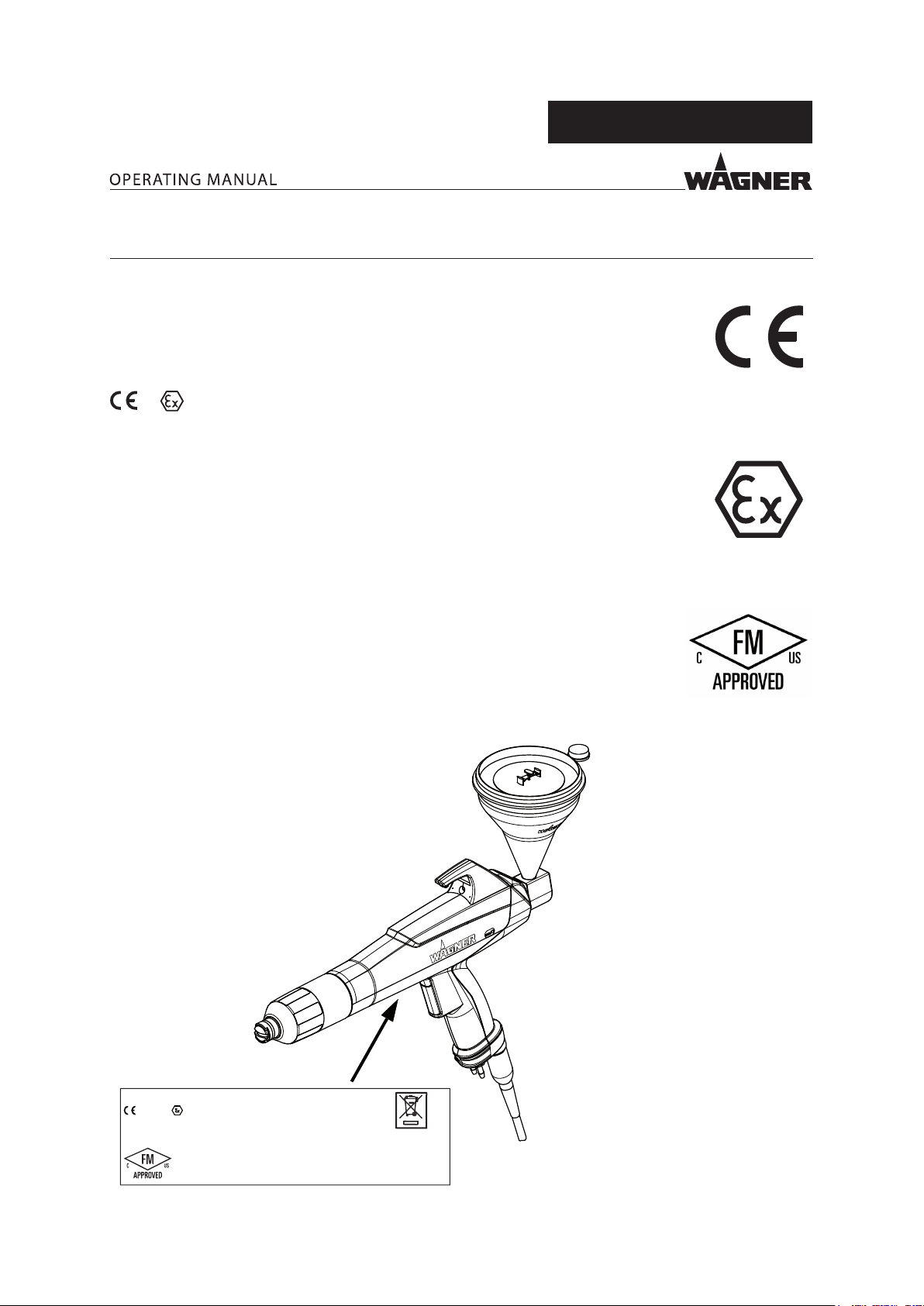
PEM-X1 CG
Powder Cup Gun
Version 05/2019
P_01725
II 2D 2mJ
0102
P_00309
Page 2

Page 3

VERSION 05/2019
ORDER NUMBER DOC2326960
PEM-X1 CG
Table of Contents
1 ABOUT THESE INSTRUCTIONS 6
1.1 Preface 6
1.2 Warnings, Notices and Symbols in these Instructions 6
1.3 Languages 7
1.4 Abbreviations 7
1.5 Terminology for the Purpose of this Manual 8
2 CORRECT USE 9
2.1 Device Type 9
2.2 Type of Use 9
2.3 For Use in Potentially Explosive Areas 9
2.4 Processible Working Materials 9
2.5 Misuse 9
3 IDENTIFICATION 10
3.1 Explosion Protection Identication 10
3.2 FM Approval 10
3.3 Type Plate 10
3.4 Permissible Device Combinations 11
4 BASIC SAFETY INSTRUCTIONS 12
4.1 Safety Instructions for the Operator 12
4.1.1 Electrical Devices and Equipment 12
4.1.2 A Safe Work Environment 13
4.1.3 Personnel Qualications 13
4.2 Safety Instructions for the Personnel 14
4.2.1 Personal Safety Equipment 14
4.2.2 Safe Handling of WAGNER Powder Spray Devices 14
4.2.3 Grounding the Device 15
4.2.4 Product Hoses 15
4.2.5 Electrical Connection Cables 16
4.2.6 Cleaning and Flushing 16
4.2.7 Maintenance and Repair 17
4.2.8 Protective and Monitoring Equipment 17
4.3 Information about Safe Discharges 18
5 DESCRIPTION 19
5.1 Construction of the Cup Gun 19
5.2 Mode of Operation of the Cup Gun 19
5.3 Scope of Delivery 20
5.4 Data 20
5.4.1 Technical Data 20
5.4.2 Dimensions 21
5.5 Accessories 21
6 ASSEMBLY AND COMMISSIONING 22
6.1 Training of Assembly/Commissioning Personnel 22
6.2 Storage Conditions 22
6.3 Installation Conditions 22
3
Page 4

VERSION 05/2019
6.4 Preparing the Cup Gun 22
6.4.1 Selection of a Suitable Nozzle System 22
6.4.2 Powder Cup 24
6.4.3 Assembling the Powder Cup 24
6.4.4 How to Use the Powder Cup 25
6.5 Connecting the Manual Gun 26
6.6 Grounding 26
6.6.1 Grounding the Powder Coating System 27
6.7 Safety Checks 27
7 OPERATION 28
7.1 Training the Operating Personnel 28
7.2 Tasks 28
7.3 Operation of the Control Unit 28
7.4 Optimizing the Powder Cloud for Coating 33
7.4.1 Recommended Settings for Total Air Volume 33
7.5 Switching O the Cup Gun 33
7.5.1 Pressure Relief/Work Interruption 33
7.6 "Double Click" Program (High Dynamic Remote) 34
7.7 Reproducible Setting of the Nozzle Position 35
ORDER NUMBER DOC2326960
PEM-X1 CG
8 CLEANING AND MAINTENANCE 36
8.1 Cleaning 36
8.1.1 Cleaning Personnel 36
8.1.2 Cleaning Procedures 36
8.2 Maintenance 36
8.2.1 Maintenance Personnel 36
8.2.2 Maintenance Instructions 37
8.2.3 Safety Checks and Maintenance Intervals 37
8.2.4 Maintenance Procedures 37
8.3 Exchanging the Manual Gun 38
8.4 Changing the Flat Jet Nozzle 39
8.4.1 Removing the Flat Jet Nozzle 39
8.4.2 Fitting the Flat Jet Nozzle 40
8.5 Changing the Round Jet Nozzle 41
8.5.1 Removing the Round Jet Nozzle 41
8.5.2 Fitting the Round Jet Nozzle 42
8.6 Replacing the Protective Wedge 43
8.6.1 Removing the Protective Wedge 43
8.6.2 Installing the Protective Wedge 44
8.7 Changing from Flat Jet Nozzle to Round Jet Nozzle 45
8.8 Assembly of the CoronaStar 47
8.9 Replacing the Suspension Hook 48
8.10 Replacing the Collector Nozzle 49
8.11 Replacing the Connecting Tube 50
9 TROUBLESHOOTING AND RECTIFICATION 51
10 INSPECTIONS 52
11 DISASSEMBLY AND DISPOSAL 54
11.1 Disassembly 54
11.2 Disposal 54
4
Page 5

VERSION 05/2019
12 ACCESSORIES 55
12.1 Flat Jet Nozzle 55
12.2 Deector Cone 55
12.3 Electrode Holder 55
12.4 Set of X1 F5 Flat Jet Nozzles 55
12.4.1 Flat Jet Nozzle X1 F5-X 56
12.5 Powder Cup 56
12.5.1 Powder Cup - 210 cm³ 56
12.5.2 1L Powder Cup 56
12.6 Cup Holder 57
12.7 CoronaStar Retrot Set 57
12.8 Wedge Tool 57
12.9 X1 VL Nozzle Extension - 150/300/500 58
12.10 X1 VL Nozzle Extension - 750 58
12.11 Wall Mount 59
12.12 Recipe Sticker 59
12.13 Powder Measuring Adapter 60
12.13.1 Powder Measuring Adapter for Flat Jet Nozzle X1 60
12.13.2 Powder Measuring Adapter for C4-F5/X1-F5 Flat Jet Nozzle 60
ORDER NUMBER DOC2326960
PEM-X1 CG
13 SPARE PARTS 61
13.1 How Can Spare Parts Be Ordered? 61
13.2 PEM-X1 CG Corona Cup Gun 62
13.3 X1 R Electrode Holder 63
13.4 Powder Cup 64
13.5 Connecting Part 64
13.6 Connecting Tube, Collector Nozzle 65
14 PEMX1 CG PORTABLE SET 66
15 EU DECLARATION OF CONFORMITY 67
15.1 EU Declaration of Conformity - Manual Gun 67
5
Page 6
VERSION 05/2019
ORDER NUMBER DOC2326960
PEM-X1 CG
1 ABOUT THESE INSTRUCTIONS
1.1 PREFACE
The operating manual contains information about safely operating, maintaining, cleaning and
repairing the device.
The operating manual is part of the device and must be available to the operating and service
personnel.
The device may only be operated by trained personnel and in compliance with this operating
manual.
Operating and service personnel should be instructed according to the safety instructions.
This equipment can be dangerous if it is not operated according to the instructions in this
operating manual.
Electrostatic manual coating systems may only be operated by qualied personnel.
1.2 WARNINGS, NOTICES AND SYMBOLS IN THESE INSTRUCTIONS
Warning instructions in this manual highlight particular dangers to users and to the
device and state measures for avoiding the hazard. These warning instructions fall into
the following categories:
DANGER
WARNING
CAUTION
NOTICE
Note:
Explanation of warning notice:
Immediate risk of danger.
Non-observance will result in death or serious injury.
Potential danger.
Non-observance may result in death or serious injury.
Potentially dangerous situation.
Non-observance may result in minor injury.
Potentially dangerous situation.
Non-observance may result in damage to property.
Provides information about particular characteristics and how
to proceed.
LEVEL OF DANGER
This notice warns you of a danger!
Possible consequences of not observing the warning notice.
The measures for preventing the hazard and its consequences.
6
Page 7

VERSION 05/2019
1.3 LANGUAGES
The operating manual is available in the following languages:
Original operating manual
Language Order no.
German 2326959
Translation of the original operating manual
Language Order no. Language Order no.
English 2326960 Polish 2410120
French 2326961
Italian 2326962
Spanish 2326963
Russian 2333347
Chinese 2333348
Additional languages on request or at: www.wagner-group.com
1.4 ABBREVIATIONS
ORDER NUMBER DOC2326960
PEM-X1 CG
Order no. Order number
Spare part
Marking in the spare parts lists
Position
Number of pieces
-- Item not available as spare part
/ Item does not exist
7
Page 8

VERSION 05/2019
1.5 TERMINOLOGY FOR THE PURPOSE OF THIS MANUAL
Cleaning
Cleaning Manual cleaning of devices and device parts with cleaning agent
Flushing Internal ushing of paint-wetted parts with compressed air
Personnel qualications
Trained person Is instructed in the tasks assigned to him/her, the potential risks
associated with improper behavior as well as the necessary
protective devices and measures.
Electrically trained
person
Electrician Can assess the work assigned to him/her and detect possible
Skilled person in the
context of
DGUV 209-052
Is instructed by an electrician about the tasks assigned to him/her,
the potential risks associated with improper behavior as well as
the necessary protective devices and measures.
hazards based on his/her technical training, knowledge and
experience in relevant provisions.
A person who, based on his/her technical training, experience
and recent vocational experience, has sucient technical
knowledge in the area of electrostatic coating and is familiar
with the relevant and generally accepted rules of technology
so that he/she can inspect and assess the status of devices and
coating systems based on workplace safety.
in TRBS1203(2010/amendment 2012): Expert knowledge in the
areas of protection against excessive pressure, electrical hazards,
and explosion protection (where applicable).
ORDER NUMBER DOC2326960
Additional requirements for skilled persons can also be found
PEM-X1 CG
8
Page 9

VERSION 05/2019
ORDER NUMBER DOC2326960
PEM-X1 CG
2 CORRECT USE
2.1 DEVICE TYPE
Powder cup guns for manual coating of grounded work pieces.
2.2 TYPE OF USE
The PEM-X1 CG powder cup gun is designed for the electrostatic coating of work pieces with
organic powders.
WAGNER explicitly prohibits any other use!
The powder cup gun may only be operated in a temperature range from 5–40 °C; 41–104 °F
(FMscope of application 5–45 °C; 41–113 °F).
Electrostatic manual coating systems may only be used in spray areas equipped in accordance
with EN 12981 or under equivalent ventilation conditions.
The device may only be operated under the following conditions:
Use the device only to work with the products recommended by WAGNER.
Do not deactivate safety xtures.
Use only WAGNER original spare parts and accessories.
The operating personnel must be trained on the basis of this operating manual.
Follow the instructions in the operating manual.
2.3 FOR USE IN POTENTIALLY EXPLOSIVE AREAS
This type A-P electrostatic powder spray gun is suitable for processing industrial powder
lacquer for coating electrically conductive objects and can be used in potentially
explosive areas (zone 22). (See Explosion Protection Identication, Chapter 3.1).
In explosion hazard areas, only use approved explosion-proof electrical devices.
2.4 PROCESSIBLE WORKING MATERIALS
– types of powder that can be charged electrostatically;
– metallic powder.
Note:
Contact your local WAGNER dealer and the lacquer manufacturer if you encounter application
problems.
2.5 MISUSE
Misuse can lead to physical injury and/or property damage!
Special attention must be paid that:
liquid coating products, e.g., solvents or water-based lacquers are not processed;
no food, medicine or cosmetics are processed.
9
Page 10
VERSION 05/2019
ORDER NUMBER DOC2326960
3 IDENTIFICATION
3.1 EXPLOSION PROTECTION IDENTIFICATION
Device type: PEM-X1 CG powder cup gun
Manufacturer: Wagner International AG
9450 Altstätten
Switzerland
PEM-X1 CG
0102
II 2D 2mJ
CE European Communities
0102 Notied body: PTB
Ex Symbol for explosion protection
II Device class II
2 Category 2
D Ex-atmosphere dust
2 mJ Maximum ignition energy 2 mJ
3.2 FM APPROVAL
The PEM-X1 CG powder cup gun is FM approved in the USA and Canada using control
document no. 2309729.
3.3 TYPE PLATE
P_00309
PEM-X1 CG
0102 II 2 D 2mJ
PTB 12 ATEX 5002 EN 50050-2
For Electro. Fin. Appl. CL. II Spray Materials
Serial Number:
Made in Switzerland
Output 100kV max.
Ambient Temperature 45 °C
In accordance with control document: 2309729
P_03875
10
Page 11

VERSION 05/2019
3.4 PERMISSIBLE DEVICE COMBINATIONS
ORDER NUMBER DOC2326960
WARNING
Incorrect use!
Risk of injury and damage to the device.
Only connect the powder cup gun to original WAGNER devices.
Only use the PEM-X1 CG powder gun cup with the following guns and control units:
Guns Control units
– PEM-X1 CG – EPG-Sprint X
– EPG-Sprint XE
– EPG-Sprint
– EPG S2
PEM-X1 CG
11
Page 12
VERSION 05/2019
ORDER NUMBER DOC2326960
4 BASIC SAFETY INSTRUCTIONS
4.1 SAFETY INSTRUCTIONS FOR THE OPERATOR
Keep this operating manual at hand near the device at all times.
Always follow local regulations concerning accident prevention regulations.
4.1.1 ELECTRICAL DEVICES AND EQUIPMENT
Danger of electric shock!
Danger to life from electric shock.
Prepare device in accordance with the local safety requirements with regard to the
operating mode and ambient inuences.
May only be maintained by skilled electricians or under their supervision.
With open housings, the mains voltage poses a danger.
Operate device in accordance with the safety regulations and electrotechnical
regulations.
Must be repaired immediately in the event of problems.
Decommission if device poses a danger or is damaged.
Must be de-energized before work is commenced. Secure the device against being
switched back on without authorization. Inform personnel about planned work.
Observe electrical safety regulations.
Ground all devices to a common grounding point.
Only operate the device with a properly installed socket with a protective ground wire
connection.
Keep liquids away from electrical devices.
PEM-X1 CG
12
Page 13
VERSION 05/2019
4.1.2 A SAFE WORK ENVIRONMENT
Danger due to dust formation!
Severe or fatal injuries due to explosion hazard or inhalation, swallowing or contact with the
skin or eyes.
The oor in the working area must be electrostatically conductive
(measurements according to EN 1081 and EN 61340-4-1).
Paint mist extraction systems/ventilation systems must be tted on site according
to local regulations.
Make sure that the ground connection and potential equalization of all system parts
are reliable and continuous and can withstand the expected stress (e.g., mechanical
stress, corrosion).
Ensure that personal protective equipment (see Chapter 4.2.1) is available and is used.
Ensure that all persons within the working area wear static dissipative shoes.
Footwear must comply with EN 20344. The measured insulation resistance must not
exceed 100 M .
Protective clothing, including gloves, must comply with EN 1149-5. The measured
insulation resistance must not exceed 100 M .
Ensure that there are no ignition sources such as naked ames, sparks, glowing wires,
or hot surfaces in the vicinity. No smoking.
Maintain sucient quantities of suitable re extinguishers and ensure that they are
serviceable.
The powder release must be electronically interlocked with the powder spray system
exhaust equipment.
Excess coating product (overspray) must be collected up safely.
The operating company must ensure that an average concentration of powder lacquer
in the air does not exceed 50% of the lower explosion limit (LEL = max. permitted
concentration of powder to air). If no reliable LEL value is available, the average
concentration must not exceed 10 g/m³.
Ensure that maintenance and safety checks are performed regularly.
In the event of defects, immediately bring the device or system to a stop and arrange
to have repairs carried out immediately.
ORDER NUMBER DOC2326960
PEM-X1 CG
4.1.3 PERSONNEL QUALIFICATIONS
Danger due to incorrect use of device!
Risk of death due to untrained personnel.
Ensure that the operating personnel has been instructed by the operator in
accordance with the operating manual and the operating instructions. The device
must only be operated, maintained and repaired by trained personnel. Refer to the
operating instructions for information about the required personnel qualications.
13
Page 14
VERSION 05/2019
4.2 SAFETY INSTRUCTIONS FOR THE PERSONNEL
Always follow the information in this manual, particularly the safety instructions and
the warning instructions.
Always follow local regulations concerning accident prevention regulations.
In electrostatics applications: Persons belonging to a risk group according to
EMF guideline 2013/35/EU (e.g., carriers of active implants), must not enter the
high-voltage area.
4.2.1 PERSONAL SAFETY EQUIPMENT
Danger due to dust formation!
Serious or fatal injuries due to inhalation, swallowing or contact with the skin or eyes.
Observe the processing regulations laid down by the manufacturer of the powder
lacquer being used, when preparing or processing the powder.
Take note of the manufacturer’s notication and the relevant environmental protection
regulations when disposing of powder lacquers.
Take the specied protective measures. In particular, wear safety goggles, protective
clothing and gloves, as well as hand protection cream if necessary.
Use a mask or breathing apparatus if necessary.
For sucient health and environmental safety: Operate the device in a powder coating
booth or on a spraying wall with the ventilation (extraction) switched on.
ORDER NUMBER DOC2326960
PEM-X1 CG
4.2.2 SAFE HANDLING OF WAGNER POWDER SPRAY DEVICES
Danger due to dust formation!
Do not point spray guns at people.
Do not spray device parts using electrostatic equipment.
Before any work on the device, in the event of work interruptions and malfunctions:
– Switch o the energy/compressed air supply.
– Relieve pressure on powder spray gun and device.
– Secure the powder spray gun against actuation.
– Disconnect the control unit from the mains.
– In the event of functional faults: remedy the fault as described in the
"Troubleshooting" chapter.
14
Page 15

VERSION 05/2019
4.2.3 GROUNDING THE DEVICE
Danger due to electrostatic charge!
Explosion hazard and damage to the device.
The electrostatic charge may, in certain cases, give rise to electrostatic charges on the device.
Flames or sparks can form during discharge.
Correct grounding of the entire coating system prevents electrostatic charges:
Ensure that all devices and tanks are grounded before each coating process.
All of the system's conductive elements, such as oors, walls, ceilings, protective
grating, transport equipment, work pieces, powder tanks, automatic moving devices
or construction parts etc. in the spray area, with the exception of parts which carry
high voltage during operation, must be connected to the grounding system.
Parts of the booth must be grounded in accordance with EN 12981.
Ensure that all persons inside the working area are grounded, e.g., that they are
wearing static dissipative shoes.
Grounding cables must be checked regularly to ensure that they are serviceable
(see EN 60204).
ORDER NUMBER DOC2326960
PEM-X1 CG
4.2.4 PRODUCT HOSES
Danger due to damaged product hoses!
The product hose may cause dangerous injuries.
Use only an original WAGNER powder hose.
Make sure that the hoses are laid only in suitable places. Hoses should not be laid in
the following places under any circumstances:
– in high-traffic areas,
– on sharp edges,
– on moving parts or
– on hot surfaces.
Ensure that the hoses are never run over by vehicles (e.g., fork lifts), or that the hoses
are never put under pressure from the outside in any other way.
Ensure that the hoses are never kinked. Observe maximum bending radii.
Ensure that no work is ever performed with a damaged hose.
Make sure that the hoses are never used to pull or move the device.
15
Page 16

VERSION 05/2019
4.2.5 ELECTRICAL CONNECTION CABLES
Risk caused by improperly laid cables!
Risk of injury and damage to the device.
Properly lay connection cables and check them regularly.
Immediately replace damaged connection cables.
Ensure that no work is ever performed with a damaged connection cable.
Do not lay connection cables on routes used by product handling vehicles and not
through doors/gates.
Do not route connection cables near aisles or walkways in order to avoid tripping.
4.2.6 CLEANING AND FLUSHING
Danger due to cleaning and ushing!
Explosion hazard and damage to the device.
Before starting cleaning or any other manual work, the high voltage in the spray area
must be shut down and locked to prevent it from being switched back on.
Lock the compressed air supply and decompress the device.
Secure the device against being switched back on without authorization.
Use only electrically conducting and grounded tanks for cleaning uids.
Preference should be given to non-ignitable cleaning uids.
If ignitable cleaning uids are used, all parts carrying high voltage must be discharged
to a discharge energy of less than 0.24 mJ, once the high voltage has been switched
o, before they can be reached. Most ignitable solvents have an ignition energy of
around 0.24 mJ or 60 nC.
The cleaning agent's ash point must be at least 15 K above the ambient
temperature.
Note the details provided by the powder lacquer manufacturer.
Only mobile industrial vacuum cleaners of design 1 (see EN 60335-2) may be used for
getting rid of dust build-up.
Take measures for workplace safety (see Chapter 4.1.2).
ORDER NUMBER DOC2326960
PEM-X1 CG
16
Page 17

VERSION 05/2019
4.2.7 MAINTENANCE AND REPAIR
Danger due to improper maintenance and repair!
Danger to life and equipment damage.
Only a WAGNER service center or a suitably trained person may carry out repairs and
replace parts.
Use only WAGNER original spare parts and accessories.
Do not change or modify the device; if change is necessary, contact WAGNER.
Only repair and replace parts that are listed in Chapter 12 and Chapter 13 that are
assigned to the device.
Do not use any defective components.
Before all work on the device and in the event of work interruptions:
– Switch o the energy and compressed air supply.
– Relieve pressure on powder spray gun and device.
– Secure the powder spray gun against actuation.
Observe the operating and service manual for all work.
4.2.8 PROTECTIVE AND MONITORING EQUIPMENT
ORDER NUMBER DOC2326960
PEM-X1 CG
Danger due to removal of protective and monitoring equipment!
Danger to life and equipment damage.
Protective and monitoring equipment must not be removed, modied or rendered
unusable.
Regularly check for perfect functioning.
If defects are detected on protective and monitoring equipment, the system must
not be operated until these defects are remedied.
To prevent electrostatic ashover, the union nut for securing the nozzles is designed in a
certain geometric shape.
This shape, together with the shape of the at jet nozzle or deector cone sleeve, prevents
the nozzles from coming loose unintentionally (see chapters 8.4, 8.5, 8.7).
To ensure safety, only use genuine WAGNER spare parts!
17
Page 18

VERSION 05/2019
4.3 INFORMATION ABOUT SAFE DISCHARGES
Designation
1 Nozzle
2 Electrode
3 Luminous discharge
4 Work piece
ORDER NUMBER DOC2326960
1
2
3
4
P_03884
PEM-X1 CG
With the high voltage switched on, a luminous or corona discharge occurs at the electrode
tip; this can only be seen in the dark. This physical eect can be seen when the electrode
is brought near the grounded work piece. This luminous discharge does not involve any
ignition energy and has no eect on system handling. When the electrode approaches the
work piece, the control unit automatically reduces the high voltage to a safe value. If you
touch plastic parts of the spray gun with your nger, harmless discharges may occur due to
the high-voltage eld around the spray gun (so-called brush discharges). However, these
do not contain any ignition energy.
18
Page 19

VERSION 05/2019
ORDER NUMBER DOC2326960
5 DESCRIPTION
5.1 CONSTRUCTION OF THE CUP GUN
12
11
PEM-X1 CG
1
2
10
7
9
7
Designation
1 Spray gun body
2 Handle
3 Electrical connection cable
4 Atomizer air connection
5 Feed air connection
6 Dosing air connection
7 Union nut
8 Trigger lever
9 Round jet nozzle
10 Flat jet nozzle
11 Suspension hook
12 Powder Cup
8
6 5
3
P_01731
4
5.2 MODE OF OPERATION OF THE CUP GUN
High voltage is activated in the manual gun when the trigger is actuated!
The air supply of the feed, dosage and atomizing air are activated at the same time, for the
powder feed.
To secure the cup gun, the control unit must be switched o.
To prevent electrostatic ashover, the union nut for securing the nozzles is designed with
a labyrinth.
19
Page 20

VERSION 05/2019
5.3 SCOPE OF DELIVERY
Order no. Designation
1 2322588 PEM-X1 CG powder cup gun
-- Nozzle set
The standard equipment includes:
1 2326024 Declaration of Conformity
1 2326959 Operating manual, in German
1 see Chapter 1.3 Operating manual in local language
5.4 DATA
5.4.1 TECHNICAL DATA
Dimensions:
Length/width/height see Chapter 5.4.2
Weight 550 g; 1.21 lbs
Cup capacity 130 g; 0.29 lb
Cup lling volume 210 cm³; 7.93 ci
ORDER NUMBER DOC2326960
PEM-X1 CG
Electrical:
Input voltage maximum 22 Vpp
Input current maximum 0.9A
Frequency 19–30 kHz
Output voltage maximum 100 kV DC
Maximum Corona current 120 µA
Polarity negative
Construction type in accordance with DIN EN 50050-2
Protection class
Pneumatic:
Input air pressure (atomizing air volume) maximum 3 bar; 0.3 MPa, 43.51 psi
Powder discharge quantity maximum 200 g/min;
maximum 0.44 lbs/min
WARNING
Exhaust air containing oil!
Risk of poisoning if inhaled.
Insucient paint application quality
Provide compressed air free from oil and water
(Quality Standard 6.5.2 according to ISO 8573.1, 2010)
6.5.2 = particle density ≤ 5 mg/m; pressure dew point ≤ +7 °C; oil content ≤ 0.1mg/m
20
Page 21

VERSION 05/2019
Ambient conditions:
If low-melting powders are used, the ambient temperature may have to be lower than 30 °C;
86 °F.
Volume measures for volumes specied in Nm³ (standard cubic meters). One cubic meter
of a gas at 0 °C and 1.013 bar is called norm cubic meter.
Ambient conditions:
Operating temperature range (CE scope of application) 5–40 °C; 41–104 °F
Operating temperature range (FM scope of application) 5–45 °C; 41–113 °F
Relative humidity < 75%
5.4.2 DIMENSIONS
ORDER NUMBER DOC2326960
PEM-X1 CG
A
Measurement mm inch
A* 365 14.37
B 230 9.06
C 290 11.42
D 45 1.77
D
C
B
P_01726
* with at jet nozzle/deector cone
5.5 ACCESSORIES
Only the accessories listed in Chapter 12 of this operating manual may be connected to
the PEM-X1 CG powder gun cup.
The accessories listed in Chapter 12 were included in the EC type examination and are
approved for use with the manual gun.
21
Page 22

VERSION 05/2019
ORDER NUMBER DOC2326960
PEM-X1 CG
6 ASSEMBLY AND COMMISSIONING
6.1 TRAINING OF ASSEMBLY/COMMISSIONING PERSONNEL
The assembly and commissioning personnel must have the technical skills to safely
commission the device.
When assembling, commissioning and carrying out all work, read and follow the operating
manuals and safety regulations for the additionally required system components.
A skilled person must check to ensure that the device is in a reliable state after it is assembled
and commissioned.
6.2 STORAGE CONDITIONS
Until the point of assembly, the device must be stored in a dry location, free from vibrations
and with a minimum of dust. The device must be stored in closed rooms.
The air temperature at the storage location must be between -20 °C and +60 °C
(-4 °F and +140 °F).
The relative air humidity at the storage location must be between 10 and 95%
(without condensation).
6.3 INSTALLATION CONDITIONS
The air temperature at the installation site must be in a range between 0 °C and 40 °C; 32 °F
and 104 °F.
The relative air humidity at the installation site must be between 10 and 95%
(without condensation).
6.4 PREPARING THE CUP GUN
6.4.1 SELECTION OF A SUITABLE NOZZLE SYSTEM
The process of changing from the at jet nozzle to the deector cone is described in
chapter 8.7.
You will nd the article numbers of the dierent nozzles in Chapter 12.
Application overview Powder cloud Nozzle
Complex part geometries Widely spread at powder cloud Flat jet nozzle
– Flat work pieces
(reduced picture frame)
– Prole
– Undercuts
Round powder cloud Deector cone
– Wire goods Size of the powder cloud is
– Grid designs
– Small components
dependent on the deector plate
diameter
P_01664
P_01665
22
Page 23

VERSION 05/2019
ORDER NUMBER DOC2326960
PEM-X1 CG
Application Distance to
work piece
(mm)
Universal
– Deep and complex part
geometries
120 … 300 50 … 300
– Extensive work pieces
The spray width can be adjusted by the sliding ring.
Rear sliding ring
Wide cloud
Cloud opening angle approx. 80°
Front sliding ring
Narrow cloud
Cloud opening angle approx. 60°
Front sliding ring, turned by 90°
Extra narrow cloud
Cloud opening angle approx. 40°
Powder
discharge
(g/min)
Nozzle
P_01664
P_03821
P_03822
P_03823
Application Distance to work piece
(mm)
18 mm 100 … 300
– Smaller at parts
25 mm 100 … 300
– Medium sized at parts
34 mm 100 … 300
– Large at parts
Deector cone
R18
P_01665
R25
P_01666
R34
P_01667
23
Page 24

VERSION 05/2019
ORDER NUMBER DOC2326960
6.4.2 POWDER CUP
Powder cup with cover, 210 cm³
P_01730
6.4.3 ASSEMBLING THE POWDER CUP
PEM-X1 CG
P_01727
Insert powder cup in opening up to stop.
24
Page 25

VERSION 05/2019
6.4.4 HOW TO USE THE POWDER CUP
ORDER NUMBER DOC2326960
PEM-X1 CG
Cover 1 is only needed on the gun if the gun is angled
such that powder escapes from the tank.
During coating, the ip-op latch 2 must be open.
It is opened by pulling up the toggle.
For storage purposes, the tank must be closed by
tting cover 1, closing ip op latch 2 and attaching
small cover 3 at the bottom of the tank.
3
2
1
P_01730
25
Page 26

VERSION 05/2019
ORDER NUMBER DOC2326960
6.5 CONNECTING THE MANUAL GUN
Designation
1 Powder cup gun
2 Electrical connection cable
3 Control unit
4 Dosing air hose (blue)
5 Feed air hose (red)
6 Atomizing air hose (black)
7 Use non-return valve with feed
and dosing air!
Procedure:
1. Switch o the high-voltage
generation on the control unit.
2. Before connecting the cup gun,
check that all components, such as
the nozzle system and union nut,
are correctly tted.
3. Connect electrical cable of the cup
gun to the control unit.
4. Connect the feed air hose to the
cup gun and to the control unit.
5. Connect the dosing air hose to the
cup gun and to the control unit.
6. Connect the atomizing air hose
to the cup gun and to the control
unit.
P_03876
PEM-X1 CG
1
2
3
I
O
4
6
5
7
6.6 GROUNDING
For safety reasons, the control unit must be properly grounded. The grounding connection
to the energy supply (socket) takes the form of the mains connection cable's protective
conductor, while that to the work piece/system is via the knurled screw on the rear of the
control unit. Both connections are absolutely essential. If installed correctly as described
above, the spray gun is grounded via the gun cable between the control unit and spray gun.
Good grounding of the work piece is also necessary for optimum powder coating.
A poorly grounded work piece causes:
– dangerous electric charging of the work piece
– very poor wrap-around
– uneven coating
– back spraying to the spray gun, i.e., contamination
26
Page 27

VERSION 05/2019
Prerequisites for perfect grounding and coating of a work piece are:
– clean suspension of the work piece to be coated,
– the grounding resistance of the work piece must not exceed 1 M
(resistance to ground measured at 500 V or 1000 V).
Sparks between conveyor, conveyor hooks (hangers) and work piece can occur
if electric contact points between conveyor, conveyor hooks (hangers) and work
piece are not suciently cleaned and therefore the work pieces are not suciently
grounded! These sparks can cause heavy radio frequency interference (EMC).
6.6.1 GROUNDING THE POWDER COATING SYSTEM
ORDER NUMBER DOC2326960
3
PEM-X1 CG
4
1
2
6
P_01120
1 Only use mains cables with grounding strand!
2 Connect the control unit's grounding cable with the signal ground!
3 Connect grounding cable to an uncoated metal part of the booth!
4 Remove all paint from hooks and other hanger parts!
5 Wear electrostatically conductive gloves!
6 Wear electrostatically conductive footwear!
7 The oor must be electrostatically conductive!
6.7 SAFETY CHECKS
A skilled person must check to ensure that the device is in a reliable state after it is assembled
and commissioned.
This includes:
– Carry out safety checks in accordance with Chapter 8.2.3.
7
5
27
Page 28

VERSION 05/2019
ORDER NUMBER DOC2326960
7 OPERATION
7.1 TRAINING THE OPERATING PERSONNEL
The operating personnel must be qualied to operate the entire system.
The operating sta must be familiar with the potential risks associated with improper
behavior as well as the necessary protective devices and measures.
Before work commences, the operating personnel must receive appropriate system
training.
7.2 TASKS
Ensure that:
the regular safety checks are carried out in accordance with chapter 8.2.3;
commissioning is carried out in accordance with Chapters 6.4 and 6.5.
7.3 OPERATION OF THE CONTROL UNIT
PEM-X1 CG
5
1 2 3 4 20 22 23 18 13 1921
9
6
10
7
11
8
12
25
100
80
2x
2x
60
40
20
kV
26
P_01743
28 27 30 29 31 32 37 35 2434 36 33
1 Illuminated display High voltage
– Lights up green
– Display range: 0-100 kV
– Resolution 10 kV
– Single LED display: Nominal voltage
– Bar display: Working voltage
Tri Cor
5
4
3
2
1
µA
50
40
Ø
120
80
40
20
10
30
12
11
20
10
9
8
10
%
0
60
3
m /h
3.0
5.5
1.5
4.5
0.5
3.5
0.3
2.5
0.1
2.0
70
Tri
80
90
%
100
SPRINT X
EPG
14
16
15
17
28
Page 29

VERSION 05/2019
2 Illuminated display: "Corona or Tribo Current"
– Lights up green
Tribo scale:
– When a Tribo gun is connected and selected
– Bar display: When powder feed is activated
– Display range: 0–5 µA
Resolution 0.5 µA
Corona scale:
– When a Corona gun is connected and selected
– Display and adjusting range: 0 [5]–120 µA,
0 [5]–20 µA resolution 5 µA
20-40 µA resolution 10 µA
40-120 µA resolution 20 µA
– Single LED display: "Trigger Point of Current Limitation"
– Bar display: Corona current
ORDER NUMBER DOC2326960
PEM-X1 CG
3 Display: "Tribo Gun"
– Lights up when a Tribo gun is connected and selected
4 Display: "Corona Gun"
– Lights up when a Corona gun is connected and selected
5 Push button: recipe for "Surface parts"
6 Push button: recipe for "Second coating"
7 Push button: recipe for "Proles"
8 Push button: recipe for "Double click"
– To access the recipe, press the trigger lever on the spray gun twice in quick
succession and hold it down
9 LED display: recipe for "Surface parts"
– Lights up green when the recipe for surface part is selected
10 LED display: recipe for "Second coating"
– Lights up green when the recipe for "Second coating" is selected
11 LED display: recipe for "Proles"
– Lights up green when the recipe for prole part is selected
12 LED display: recipe for "Double click"
– Lights up green, when the recipe for "Double click" is selected
13 LED display: "Fault"
– Lights up, when there is a fault on the device
29
Page 30

VERSION 05/2019
14 LED display: "Automatic gun"
– Lights up, when an automatic gun is connected
15 Push button: "Standby"
– To switch into standby mode
– High voltage and powder feed cannot be activated in this mode
– To reactivate normal mode, press the button again
16 LED display: "Standby"
– Lights up when the device is in standby mode
17 Push button: "Flush"
– To activate the injector and the hose ushing
18 LED display: "Flush"
– Lights up blue, when the ush function is activated
ORDER NUMBER DOC2326960
PEM-X1 CG
19 LED display, 7 segments, three-digit number
– Indicates the exact value depending on the activated function:
"Total air volume; atomizing, ionizing and Tribo air; additional recipes; high voltage;
current limitation; powder quantity"
– Display showing error number in the event of warnings and malfunctions
20 Push button: "Total air volume"
– To activate the function, the value is precisely adjusted with rotary controller 24
and is indicated in LED display 19
– Adjusting range: 2-6 m³/h
– Resolution: 0.05 m³/h
21 Push button: "Atomizing, ionizing and Tribo air"
– To activate the function, the value is precisely adjusted with rotary controller 24
and is indicated in LED display 19
– Adjusting range: 0.1-4 m³/h
– Resolution: 0.05 m³/h
22 LED display: "Total air"
– Lights up yellow, when the setting "Total air" is selected
23 LED display: "Atomizing, ionizing and Tribo air"
– Lights up yellow, when the setting "Atomizing, ionizing and Tribo air" is selected
30
Page 31

VERSION 05/2019
24 Universal control dial
– Dynamic digital control dial with 32 positions per revolution
– Adjustment speed is proportional to rotational speed
– Used to set: "Total air volume; atomizer, ionizer and Tribo air; additional recipes;
High voltage; Current limitation; Powder quantity"
– For setting parameter values in conguration mode
25 Push button: "Additional recipes"
– To activate the function, the Additional recipes adjustment is set with the control
dial 24 and is indicated in the LED display 19.
– Selection of the recipes 5 to 50
26 LED display: "Additional recipes"
– Lights up yellow, when an additional recipe is selected
27 Push button "High voltage"
– To activate the function, the high voltage is set with control dial 24 and is indicated
in LED Display 19
– Adjusting range: 10–100 kV
– Resolution: 1 kV
ORDER NUMBER DOC2326960
PEM-X1 CG
28 LED display: "High voltage"
– Lights up yellow. The high voltage is selected and can be adjusted using control dial 24
29 Push button: "Current limitation"
– To activate the function, the current limitation is set with the control dial 24 and is
indicated in the LED display 19
– Adjusting range: 5–120 µA
– Resolution: 1 µA
30 LED display: "Current limitation"
– Lights up yellow. The current limitation is selected and can be adjusted using the
control dial (24).
31 Push button: "Characteristic slope"
– To switch the characteristic slope
– Display with LED 32
32 LED display: "Characteristic slope"
– Lights up green
– Lower LED characteristic curve, at
– Middle LED characteristic curve, medium
– Upper LED characteristic curve, steep
31
Page 32

VERSION 05/2019
33 Illuminated display: "Powder quantity"
– Lights up green
– Display range: 0–100%
– Resolution: 3.33%
– Single LED display: Set point (high voltage and powder are deactivated)
– Bar display: Actual value (high voltage and powder are activated)
34 Illuminated display: "Total air volume"
– Lights up green
– Display range: 2–6 m³/h
– Resolution: 0.2–0.5 m³/h
– Single LED display: Set point (high voltage and powder are deactivated)
– Bar display: Actual value (high voltage and powder are activated)
35 Illuminated display: "Atomizing, ionizing and Tribo air volume"
– Lights up green
– Display range: 0.1–4 m³/h
– Resolution: 0.1–1.0 m³/h
– Single LED display: Set point (high voltage and powder are deactivated)
– Bar display: Actual value (high voltage and powder are activated)
ORDER NUMBER DOC2326960
PEM-X1 CG
36 Push button: "Powder quantity"
– To activate the function, the powder quantity is set with control dial 24 and is
indicated in LED display 19.
– Adjusting range: 1–100%
– Resolution: 1%
37 LED display: "Powder quantity"
– Lights up yellow, when the powder quantity is selected
32
Page 33

VERSION 05/2019
ORDER NUMBER DOC2326960
7.4 OPTIMIZING THE POWDER CLOUD FOR COATING
Procedure:
1. Switch on the high-voltage generation and the powder feed.
Note:
To minimize wear on the wearing parts, the total air volume should be below 5 Nm³/h.
The atomizing air should be adjusted for the
– at jet nozzle to 0.1 Nm³/h
– round jet nozzle to > 0.2 Nm³/h
2. Adjust the powder quantity and the powder speed on a test piece.
7.4.1 RECOMMENDED SETTINGS FOR TOTAL AIR VOLUME
3
m /h
Ø
5.5
12
4.5
11
3.5
10
9
2.5
8
Tribo Corona
[µA] [Nm³/h] [%][kV]
2.0
PEM-X1 CG
50
40
60
30
20
10
70
80
90
0 %
100 %
90 80 2.0 50
2x
2x
50 30 1.5 40
60 40 1.2 40
82 20 1.8 30
P_01828
7.5 SWITCHING OFF THE CUP GUN
When releasing the trigger, the powder feed is stopped and the high voltage switched o.
To safely switch o the cup gun, e.g., for maintenance work, the control unit must be switched o.
7.5.1 PRESSURE RELIEF/WORK INTERRUPTION
Carry out the work steps as described in the "Pressure relief" chapter:
– if pressure relief is required,
– if the coating work is interrupted or stopped,
– before the device is cleaned on the outside, checked, or serviced,
– before the spray nozzle is installed or cleaned.
33
Page 34

VERSION 05/2019
ORDER NUMBER DOC2326960
PEM-X1 CG
7.6 "DOUBLE CLICK" PROGRAM HIGH DYNAMIC REMOTE
This function is used to change quickly to another program during a coating operation.
The operator can access a previously set program by double-clicking on the trigger lever
on the manual gun, for example to recoat parts using dierent parameters (high-voltage,
current limitation, air volumes etc.).
To access the function, press the trigger lever on the manual gun twice in quick succession
and hold down. Upon releasing the trigger, the original program will be returned to.
Tri Cor
120
5
100
80
4
80
2x
2x
40
3
60
20
2
40
10
1
20
µA
kV
P_01733
Tri Cor
120
5
100
2x
2x
100
2x
2x
80
4
80
40
3
60
20
2
40
10
1
20
µA
kV
Tri Cor
120
5
80
4
80
40
3
60
20
2
40
10
1
20
µA
kV
2x
34
Page 35

VERSION 05/2019
7.7 REPRODUCIBLE SETTING OF THE NOZZLE POSITION
An adjustment tool is provided for the at jet nozzle.
It permits turning the at jet nozzle without damaging the
electrodes and without removing the union nut.
The union nut only has to be loosened.
ORDER NUMBER DOC2326960
PEM-X1 CG
P_01671
35
Page 36

VERSION 05/2019
ORDER NUMBER DOC2326960
PEM-X1 CG
8 CLEANING AND MAINTENANCE
8.1 CLEANING
8.1.1 CLEANING PERSONNEL
Cleaning work should be undertaken regularly and carefully by qualied and trained personnel.
They should be informed of specic hazards during their training.
The following hazards may arise during cleaning work:
– health hazard from inhaling powder lacquer,
– use of unsuitable cleaning tools and aids.
8.1.2 CLEANING PROCEDURES
The cleaning intervals should be adapted by the operator depending on the level of use
and if necessary the level of soiling.
If in doubt, we recommend contacting WAGNER's specialist personnel.
Procedure:
1. End the coating procedure.
2. Press "Flush" button on control unit.
Let the cleaning function run until the powder cup is completely empty.
3. Push the "Flushing" button on the control unit, in order to switch o the cleaning
function.
4. Remove the powder cup from the cup gun.
5. Clean the powder cup and powder cup's cover with compressed air.
6. Unscrew the union nut with nozzle system from the cup gun.
7. Press the nozzle system out of the union nut and clean all parts thoroughly.
8. Thoroughly blow out the cup gun from the rear, on the cup gun tting, and from
the front.
9. Assemble the nozzle system and, with the union nut, attach it to the cup gun.
10. Attach the powder cup, ll it with powder and put on the cover.
11. Continue the coating process.
8.2 MAINTENANCE
8.2.1 MAINTENANCE PERSONNEL
Maintenance work should be undertaken regularly and carefully by qualied and trained
personnel. They should be informed of specic hazards during their training.
The following hazards may arise during maintenance work:
– health hazard from inhaling powder lacquer,
– use of unsuitable tools and aids.
A skilled person must ensure that the device is checked for being in a reliable state after
maintenance work is completed.
36
Page 37

VERSION 05/2019
8.2.2 MAINTENANCE INSTRUCTIONS
ORDER NUMBER DOC2326960
DANGER
Incorrect maintenance/repair!
Danger to life and equipment damage.
Only a WAGNER service center or a suitably trained person may carry out repairs and
replace parts.
Only repair and replace parts that are listed in the "Spare parts" chapter and that are
assigned to the unit.
Before all work on the device and in the event of work interruptions:
– Switch o the energy and compressed air supply.
– Relieve spray gun and device pressure.
– Secure the spray gun against actuation.
Observe the operating and service manual for all work.
Prior to maintenance
– Flush and clean the system. Chapter 8.1.2
After maintenance
– Carry out safety checks in accordance with Chapter 8.2.3.
– Put the system into operation and check for leaks.
– Have the system checked for safe condition by a skilled person.
PEM-X1 CG
8.2.3 SAFETY CHECKS AND MAINTENANCE INTERVALS
Daily: Before starting work, carry out a visual inspection to ensure that the system is grounded.
8.2.4 MAINTENANCE PROCEDURES
The maintenance intervals should be adapted by the operator depending on the level of
use and if necessary the level of soiling.
If in doubt, we recommend contacting WAGNER's specialist personnel.
Maintenance work Time stamp
once each shift weekly
Blow out gun and check for sintering
Check gun settings
Check gun discharge pressure
Blow out powder hoses
Check grounding
Check compressed air quality
Check gun voltage
Check powder hoses for bends and sintering
37
Page 38

VERSION 05/2019
8.3 EXCHANGING THE MANUAL GUN
Before exchanging the manual gun, any power residue must be thoroughly removed.
The wearing parts in the manual gun, marked in the spare parts list with " ", must be regularly
checked and replaced as necessary.
ORDER NUMBER DOC2326960
6
PEM-X1 CG
1
4 5
3
2
P_01732
Procedure:
1. Switch o control unit.
2. Disconnect electrical cable 1 from control unit 2.
3. Disconnect dosing air hose 3, feed air hose 4 and atomizing air hose 5 from spray gun 6.
4. Connect dosing air hose 3, feed air hose 4 and atomizing air hose 5 to new spray gun 6.
5. Connect electrical cable 1 to control unit 2.
6. Switch on the control unit.
7. The spray gun is ready for use again.
38
Page 39

VERSION 05/2019
8.4 CHANGING THE FLAT JET NOZZLE
8.4.1 REMOVING THE FLAT JET NOZZLE
Procedure:
1. Unscrew union nut from gun housing.
2. Take union nut with nozzle system o gun body.
The nozzle system remains inserted in the union nut.
Note:
If the nozzle system doesn't remain inserted in the union nut,
the nozzle system and union nut must be replaced.
3. The parts can be separated by gently pressing the sliding ring
on the at jet nozzle.
4. Remove powder residues from the removed parts and from
the manual gun.
Note:
Never place the manual gun or parts of the manual gun in
cleaning agent.
As a rule, the protective wedge needs to be checked for
wear and replaced if necessary.
ORDER NUMBER DOC2326960
PEM-X1 CG
1.
2.
3.
P_01673
39
Page 40

VERSION 05/2019
8.4.2 FITTING THE FLAT JET NOZZLE
Procedure:
1. Before inserting the electrode holder, the spring contact of
the gun body and contact surface of the electrode holder
should be checked.
The spring contact must be clean and smooth-running, the
gun body must also be clean and free of powder deposits.
2. Insert electrode holder into gun housing.
3. Attach at jet nozzle to electrode holder and attach union nut.
4. Screw union nut onto gun housing until at jet nozzle can
no longer be turned by hand.
ORDER NUMBER DOC2326960
PEM-X1 CG
2.
3.
4.
P_01674
40
Page 41

VERSION 05/2019
8.5 CHANGING THE ROUND JET NOZZLE
8.5.1 REMOVING THE ROUND JET NOZZLE
Procedure:
1. Pull o deector cone.
2. Unscrew union nut from gun housing.
3. Take union nut with nozzle system o gun body.
The nozzle system remains inserted in the
union nut.
Note:
If the nozzle system doesn't remain inserted
in the union nut, the nozzle system and union
nut must be replaced.
4. Press nozzle system out of union nut by gently
pressing on deector cone sleeve.
5. Remove powder residues from the removed
parts and from the spray gun.
Note:
Never place the spray gun or parts of the spray
gun in cleaning agent.
As a rule, the protective wedge needs to be
checked for wear and replaced if necessary.
ORDER NUMBER DOC2326960
PEM-X1 CG
1.
2.
3.
4.
P_01677
41
Page 42

VERSION 05/2019
8.5.2 FITTING THE ROUND JET NOZZLE
Procedure:
1. Before inserting the electrode holder, the spring contact of the
gun body and contact surface of the electrode holder should
be checked.
The spring contact must be clean and smooth-running, the
gun body must also be clean and free of powder deposits.
2. Attach deector cone sleeve onto electrode holder.
3. Insert electrode holder into gun housing.
4. Slide union nut onto gun housing.
5. Screw union nut onto gun housing (hand-tight).
6. Slide deector cone over deector cone sleeve.
ORDER NUMBER DOC2326960
PEM-X1 CG
2.
3.
6.
4.
5.
P_01678
42
Page 43

VERSION 05/2019
8.6 REPLACING THE PROTECTIVE WEDGE
8.6.1 REMOVING THE PROTECTIVE WEDGE
Note:
A wedge tool is available to prevent the protective wedge from being damaged when
dismantling and inserting.
The wedge tool has a removal side (E) and an attachment side (A). Use the right side for the
corresponding procedure!
You will nd the necessar y wearing parts and spare parts in Chapter 13 of this operating manual.
ORDER NUMBER DOC2326960
PEM-X1 CG
1 Wedge tool
2 Electrode holder (shown with a cut-away view
to improve comprehension)
3 Protective wedge (when positioned)
Procedure:
1. Guide wedge tool 1 into electrode holder 2 up
to stop.
2. Pull protective wedge 3 out of electrode holder 2
using wedge tool 1.
3. Press protective wedge 3 sideways out of wedge
tool 1 manually (without tool).
1.
A
1
E
2
3
2.
3.
P_01675
43
Page 44

VERSION 05/2019
8.6.2 INSTALLING THE PROTECTIVE WEDGE
Note:
The same wedge tool is used to insert the protective wedge.
Procedure:
1. Guide protective wedge into wedge tool.
2. Insert both parts into opening on electrode
holder up to stop.
If it is not possible to push the wedge tool in as
far as the X mark, rotate the wedge tool a little
until it can be pushed up to the mark.
The mark X must be ush with the Y end of the
electrode holder.
3. The protective wedge is now correctly assembled
and the wedge tool can be pulled out of the
electrode holder.
4. The protective wedge remains inserted in the
electrode holder.
Prior to re-tting, check whether the contact
points on electrode holder and in gun housing
have been thoroughly cleaned so that the
electrode tip is electrically connected to the
high-voltage generator.
5. Mount fan or round jet nozzle with the
corresponding electrode holder.
ORDER NUMBER DOC2326960
1.
2.
PEM-X1 CG
X
Y
P_01676
3.
44
Page 45

VERSION 05/2019
8.7 CHANGING FROM FLAT JET NOZZLE TO ROUND JET NOZZLE
The standard Corona cup gun is delivered with a at jet nozzle. The nozzle can be changed
easily, as described below.
The X1 R electrode holder is necessary to perform the change.
ORDER NUMBER DOC2326960
PEM-X1 CG
CAUTION
Electrode tip!
Risk of injury and damage to the device.
Take care when tting the X1 R electrode holder.
Procedure:
1. Unscrew union nut from gun housing.
2. Take union nut with nozzle system o gun body.
The nozzle system remains inserted in the union nut.
Note:
If the nozzle system doesn't remain inserted in the union nut,
the nozzle system and union nut must be replaced.
3. The parts can be separated by gently pressing the sliding ring on
the at jet nozzle.
4. Attach deector cone sleeve onto X1 R electrode holder.
1.
4.
2.
3.
P_01679
45
Page 46

VERSION 05/2019
Procedure:
5. Before inserting the electrode holder, the spring contact of
the gun body and contact surface of the electrode holder
should be checked.
The spring contact must be clean and smooth-running, the
gun body must also be clean and free of powder deposits.
6. Insert electrode holder into gun housing.
7. Slide union nut onto gun housing.
8. Screw union nut onto gun housing (hand-tight).
9. Slide deector cone over deector cone sleeve.
ORDER NUMBER DOC2326960
PEM-X1 CG
6.
9.
7.
8.
P_01690
46
Page 47

VERSION 05/2019
8.8 ASSEMBLY OF THE CORONASTAR
The CoronaStar is a retrot set for the manual gun, which helps to achieve a better
surface quality (e.g., reduction of "orange peel").
ORDER NUMBER DOC2326960
WARNING
Danger from electric current!
Risk of injury and damage to the device.
The conversion on the CoronaStar may only be carried out by trained personnel.
Prior to assembling the CoronaStar, the high voltage and powder feed must be
switched o and secured against being inadvertently switched on.
Procedure:
1. Guide plug-in contact 1 of CoronaStar into drilled
hole B on hook.
2. Attach clip 2 of CoronaStar to housing.
Flexible positioning in a range of ± 90° is possible.
2
PEM-X1 CG
1
B
±90°
P_01729
47
Page 48

VERSION 05/2019
8.9 REPLACING THE SUSPENSION HOOK
Procedure:
1. Loosen fastening screws on rear of hook and
unscrew.
2. Slide hook in direction indicated by arrow and
remove from gun housing.
3. Fit new hook on receiver and slide in direction
indicated by arrow.
4 Fit fastening screws and tighten.
ORDER NUMBER DOC2326960
PEM-X1 CG
1.
2.
3.
4.
P_01734
48
Page 49

VERSION 05/2019
8.10 REPLACING THE COLLECTOR NOZZLE
The collector nozzle can be replaced if worn (for order number, see Chapter 13.6).
1. Remove the powder cup from the gun.
Unscrew screws 1 and remove connecting part 2 from
gun body.
2. Pull collector nozzle 3 out of gun body.
3. Carefully insert new collector nozzle 3 in gun body.
4. Attach connecting part 2 to gun body and fasten with screws 1
(torque 40±10 Ncm).
Insert powder cup in connecting part.
ORDER NUMBER DOC2326960
1.
2.
PEM-X1 CG
2
1
3.
4.
3
3
2
1
P_01735
49
Page 50

VERSION 05/2019
8.11 REPLACING THE CONNECTING TUBE
The connecting tube can be replaced if worn (for order number, see Chapter 13.6).
1. Remove the powder cup from the gun.
Unscrew screws 1 and remove connecting part 2 from
gun body.
2. Unscrew connecting tube 3 from gun body.
3. Screw new connecting tube 3 into gun body.
4. Attach connecting part 2 to gun body and fasten with screws 1
(torque 40±10 Ncm).
Insert powder cup in connecting part.
ORDER NUMBER DOC2326960
1.
2.
PEM-X1 CG
2
1
3.
4.
3
3
2
1
P_01736
50
Page 51

VERSION 05/2019
ORDER NUMBER DOC2326960
PEM-X1 CG
9 TROUBLESHOOTING AND RECTIFICATION
DANGER
Incorrect maintenance/repair!
Danger to life and equipment damage.
WAGNER devices, protective systems and safety, monitoring and control equipment
may only be serviced/repaired as dened in Directive 2014/34/EC (ATEX) by trained
WAGNER service personnel or skilled persons in accordance with TRBS 1203!
Note national regulations!
Service, repair or replacement of devices or parts of devices may only be performed
outside the hazard area!
Malfunction Cause Remedy
No electrostatic (e.g., no wrap
around or no powder adhesion)
Poor powder wrap-around
Back-spray
Powder outlet uneven or
inadequate
Spray pattern is uneven – Parts of nozzle system worn – Replace worn parts
Cracks in the gun housing – Improper handling of the
– Fault in the high-voltage
generator
– Electrical cable from spray gun
to control unit faulty
– Cascade in spray gun faulty – Contact a WAGNER service center
– Insucient or no grounding – See Chapter 6.6
– Contamination – Blow through powder feeding
– Powder sintering – Clean powder feeding parts
– Collector nozzle contaminated – Thoroughly clean cup gun
– Feed air / dosing air ratio incorrect – Adjust at control module resp.
– Collector nozzle worn – Replace collector nozzle¹)
powder spray gun
– Contact a WAGNER service center
– Contact a WAGNER service center
parts
control unit
– Gun housing must be replaced
– Contact a WAGNER service center
1.) The wearing and spare parts are listed in Chapter 13.
51
Page 52

VERSION 05/2019
ORDER NUMBER DOC2326960
PEM-X1 CG
10 INSPECTIONS
If the system is used for electrostatic coating with ignitable coating powders, testing should be
undertaken in accordance with DIN EN 50050-2: 2014 as per Table 1.
52
Page 53

VERSION 05/2019
interval
weekly
Type of inspection Inspection
ORDER NUMBER DOC2326960
annually
weekly
PEM-X1 CG
by
Measure resistance to ground
SP ME/CM
work piece's attachment point must
The resistance to ground of every
potential)
(work piece receiver - ground
not exceed 1 M (measurement
voltage must be 1000 V). The form
max. 1 M @ 1000 V.
of construction of the work piece
work pieces remain grounded
mount must guarantee that the
during coating.
stopped and the powder feed,
supply air, and high voltage
Test whether the system is safely
SP FT
be interlocked such that the
powder feed and high voltage
The technical ventilation should
cannot be switched on, while the
ventilation is shut down.
are switched o when the
technical ventilation is not working
eectively.
Inspect and test
(e.g., by measurement) whether
SP FT
Electrostatic manual coating
undamaged condition. Damaged
systems may only be operated in an
puts people at risk.
all parts carrying high voltage
do not result in discharge which
immediately and repaired
immediately.
devices must be decommissioned
Section Type of inspection Requirements Inspection
from the work piece
attachment point
1 Ground leaking resistance
high voltage, compressed air
ventilation equipment and
2 Link between technical
and powder feed
3 Checking the electrostatic
manual coating system for
damage
Legend:
MF = Manufacturer FT = Function test
ER = Employer ME = Measurement
SP = Skilled person OC = Organization check
FPO = Fire prevention ocer VI = Visual inspection
ELT = Electrician CM = Constant monitoring
TP = Trained person TT = Technical testing
53
Page 54

VERSION 05/2019
ORDER NUMBER DOC2326960
11 DISASSEMBLY AND DISPOSAL
11.1 DISASSEMBLY
WARNING
Incorrect disassembly!
Risk of injury and damage to the device.
Before starting disassembly:
– Switch o the energy and compressed air supply.
– Ensure that all system components are grounded.
– Secure system against being switched back on without authorization.
Observe the operating manuals when carrying out all work.
Procedure:
1. Switch o the system.
2. Lock the compressed air supply and decompress system.
3. Disconnect the gun connection cable from control unit.
4. Disconnect the hose for feed air, dosing air and atomizing air from the spray gun
and from the control unit.
PEM-X1 CG
11.2 DISPOSAL
NOTICE
Do not dispose of used electrical equipment with household
refuse!
In accordance with European Directive 2012/19/EU on the disposal
of used electrical equipment and its implementation in national law,
this product may not be disposed of with the household refuse, but
must be recycled in an environmentally correct manner.
WAGNER or one of our dealers will take back your used WAGNER
electric or electronic equipment and will dispose of it for you in an
environmentally-friendly way. To arrange this, please contact one of
our service centers, one of our representatives or us directly.
54
Page 55

VERSION 05/2019
ORDER NUMBER DOC2326960
12 ACCESSORIES
12.1 FLAT JET NOZZLE
Order no. Designation
2321976 Flat jet nozzle, X1, complete
12.2 DEFLECTOR CONE
Order no. Designation
2321981 Deector cone, D18, complete
PEM-X1 CG
P_01664
P_01665
2321980 Deector cone, D25, complete
2321171 Deector cone, D34, complete
12.3 ELECTRODE HOLDER
Order no. Designation
2322529 Electrode holder, X1 F ET
2322490 Electrode holder, X1 R ET
12.4 SET OF X1 F5 FLAT JET NOZZLES
The X1 F5 nozzles are intended for processing metallic powders.
Order no. Designation
P_01666
P_01667
P_01691
P_01692
2387104 Set of at jet nozzles X1 F5
For further details, see assembly manual, order no. 2389361.
P_03825
55
Page 56

VERSION 05/2019
12.4.1 FLAT JET NOZZLE X1 F5X
Order no. Designation
2390036 Flat jet nozzle X1 F5-X
12.5 POWDER CUP
12.5.1 POWDER CUP 210 CM³
ORDER NUMBER DOC2326960
PEM-X1 CG
P_03594
Order no. Designation
2324139 1 x cup with cover
2324140 5 x cup with cover
12.5.2 1L POWDER CUP
Order no. Designation
2399466 1 x cup with cover
2399467 5 x cup with cover
2399468 10 x cup with cover
2399469 50 x cup with cover
P_01730
P_03877
56
Page 57

VERSION 05/2019
ORDER NUMBER DOC2326960
12.6 CUP HOLDER
Order no. Designation
2399470 Cup holder for PEM-X1 CG 1L cup
12.7 CORONASTAR RETROFIT SET
PEM-X1 CG
P_03878
P_01695
1
Order no. Designation
2322868 CoronaStar, PEM-X1, complete
1 2322835 CoronaStar electrode, PEM-X1 ET
12.8 WEDGE TOOL
P_01696
Order no. Designation
1 2324124 Wedge tool, X1 + 20 wedges
Available as an accessory, not included in the scope of delivery
57
Page 58

VERSION 05/2019
ORDER NUMBER DOC2326960
12.9 X1 VL NOZZLE EXTENSION 150/300/500
Order no. Designation
1 2323366 Nozzle extension, X1 VL 150 (150 mm; 5.91 inches)
1 2323356 Nozzle extension, X1 VL 300 (300 mm; 11.81 inches)
1 2323338 Nozzle extension, X1 VL 500 (500 mm; 19.68 inches)
1 2324147 Flat jet nozzle, X1 VL ET
1 2324148 Round jet nozzle, X1 VL ET
PEM-X1 CG
P_01697
Available as an accessory, not included in the scope of delivery
12.10 X1 VL NOZZLE EXTENSION 750
Order no. Designation
1 2330497 Nozzle extension, X1 VL 750 (750 mm; 29.53 inches)
1 2324147 Flat jet nozzle, X1 VL ET
1 2324148 Round jet nozzle, X1 VL ET
Available as an accessory, not included in the scope of delivery
P_02163
58
Page 59

VERSION 05/2019
12.11 WALL MOUNT
Order no. Designation
2330223 Wall mount with bracket
12.12 RECIPE STICKER
2x
2x
name 80 100 4.5 80
P5
P6
P7
P8
P9
P10
ORDER NUMBER DOC2326960
P_01861
50
40
60
3
m /h
Ø
12
11
10
9
8
Tribo Corona
[µA] [Nm³/h] [%][kV]
90 80 4.0 70
50 20 3.6 57
70 40 3.6 50
82 20 3.6 45
70
30
5.5
4.5
20
3.5
2.5
2.0
80
90
10
0 %
100 %
______________________________
✆
______________________________
@
www.wagner-group.com/industry
www
m /h
[Nm³/h]
0.1
> 0.2
2x
PEM-X1 CG
3
Tri
3.0
1.5
0.5
0.3
0.1
Order no. Designation
2331223 Recipe sticker
P_01829
59
Page 60

VERSION 05/2019
12.13 POWDER MEASURING ADAPTER
ORDER NUMBER DOC2326960
PEM-X1 CG
WARNING
Risk of explosion due to electrostatic charging!
Danger to life and equipment damage.
Only use powder measurement adapter when high voltage is switched o!
The powder measuring adapter serves to measure powder quantities for the PEM-X1 CG gun.
The powder measuring adapter is slid onto the nozzle.
12.13.1 POWDER MEASURING ADAPTER FOR FLAT JET NOZZLE X1
P_01716
Order no. Designation
2325320 Powder measuring adapter with X1 bag, complete
12.13.2 POWDER MEASURING ADAPTER FOR C4F5/X1F5 FLAT JET NOZZLE
P_04197
Order no. Designation
2403425 Powder measuring adapter, C4-F5/X1-F5, complete
60
Page 61

VERSION 05/2019
ORDER NUMBER DOC2326960
PEM-X1 CG
13 SPARE PARTS
13.1 HOW CAN SPARE PARTS BE ORDERED?
Always supply the following information to ensure delivery of the right spare part:
Order number, designation and quantity
The quantity need not be the same as the number given in the quantity column " " on the list.
This number merely indicates how many of the respective parts are used in each component.
The following information is also required to ensure smooth processing of your order:
− billing address
− delivery address
− name of the person to be contacted in the event of any queries
− type of delivery (normal mail, express delivery, air freight, courier etc.)
Identication in spare parts lists
Explanation of column " " (labeling) in the following spare parts lists:
Wearing parts. Wearing parts are not included in the warranty terms.
Included in service set
Note:
These parts are not covered by warranty terms.
Not part of standard equipment, however, available as special accessory.
Explanation of order no. column
-- Item not available as spare part.
/ Position does not exist.
DANGER
Incorrect maintenance/repair!
Danger to life and equipment damage.
Only a WAGNER service center or a suitably trained person may carry out repairs and
replace parts.
Use only WAGNER original spare parts and accessories.
Only repair and replace parts that are listed in the "Spare parts" chapter and that are
assigned to the unit.
Before all work on the device and in the event of work interruptions:
– Switch o the energy and compressed air supply.
– Relieve spray gun and device pressure.
– Secure the spray gun against actuation.
Observe the operating and service manual for all work.
61
Page 62

VERSION 05/2019
13.2 PEMX1 CG CORONA CUP GUN
ORDER NUMBER DOC2326960
PEM-X1 CG
13
4
5
2
P_01737
3
7
6
1
11
8
9
12
10
62
Page 63

VERSION 05/2019
Order no. Designation
1 2322588 Corona cup gun, PEM-X1 CG
2 2320464 Union nut, X1
3 2321976 Flat jet nozzle, X1, complete
4 2322529 Electrode holder, X1 F ET
5 2320488 Replacement protective wedge X1
6 2320330 Gun hook, X1 ET
7 2316896 Screw
8 2324135 Connecting tube, ET
9 2324133 Collector nozzle, ET
10 2324132 Connecting part, ET
11 9971313 O-ring
12 9906023 Screw
13 2324205 Wedge tool, X1
2324223 Non-return valve, complete
2343544 Hose kit, PEM-X1 CG ET
ORDER NUMBER DOC2326960
PEM-X1 CG
13.3 X1 R ELECTRODE HOLDER
1
7
6
5
Order no. Designation
1 1 2322493 Electrode holder, X1 R, with nozzle
2 1 2322490 Electrode holder, X1 R ET
3 1 2320488 Replacement protective wedge X1
4 1 2320503 Deector cone sleeve, X1
5 1 2321981 Deector cone, D18, complete
6 1 2321980 Deector cone, D25, complete
7 1 2321171 Deector cone, D34, complete
4
2
3
P_01700
63
Page 64

VERSION 05/2019
13.4 POWDER CUP
ORDER NUMBER DOC2326960
4
PEM-X1 CG
P_01730
Order no. Designation
1 1 2324139 Cup with cover, X1 ET
2 5 2324140 Cup with cover, X1 ET
3 1 2323145 Cup, X1
4 1 2322906 Cover
13.5 CONNECTING PART
3
1, 2
2
1
P_01738
Order no. Designation
1 1 2324132 Connecting part, ET
2 2 9971313 O-ring
64
Page 65

VERSION 05/2019
13.6 CONNECTING TUBE, COLLECTOR NOZZLE
ORDER NUMBER DOC2326960
4
PEM-X1 CG
2
1
P_01739
3
Order no. Designation
1 1 2324135 Connecting tube, ET
2 1 9971445 O-ring
3 1 2324133 Collector nozzle, ET
4 1 9974210 O-ring
5 1 9971462 O-ring
5
65
Page 66

VERSION 05/2019
ORDER NUMBER DOC2326960
14 PEMX1 CG PORTABLE SET
The PEM-X1 CG portable set is mainly designed for laboratory tests, sample coatings or
small series production.
PEM-X1 CG
Order no. Designation
2328172 PEM-X1 CG portable set
Operating position and connecting parts
66
Page 67

VERSION 05/2019
ORDER NUMBER DOC2326960
15 EU DECLARATION OF CONFORMITY
15.1 EU DECLARATION OF CONFORMITY MANUAL GUN
Herewith we declare that the supplied version of:
PEM-X1 CG
complies with the following guidelines:
2014/34/EU
2006/42/EC
2014/30/EU
2011/65/EU
2012/19/EU
Applied standards, in particular:
EN ISO 12100: 2010 EN 50050-2:2013
EN 1953:2013 EN 1127-1:2011
EN ISO 13732-1: 2008 EN 61000-6-2: 2005+B: 2011
EN 14462:2015 EN 61000-6-4: 2007+A1: 2011
EN 60529: 1991+A1: 2000+A2: 2013 EN ISO/IEC 80079-34: 2011
Applied national technical standards and specications, in particular:
DGUV-I 209-052 TRGS 727
PEM-X1 CG
Identication:
EU Declaration of Conformity
The EU Declaration of Conformity is enclosed with this product. If needed, further copies can
be ordered through your WAGNER dealer by specifying the product name and serial number.
Order number: 2326024
0102
PTB 12 ATEX 5002
EN 50050-2:2013
II 2D 2mJ
67
Page 68

686970
Page 69

Page 70

Page 71

Page 72

C
E
R
T
I
F
I
E
D
Order no. 2326960
Edition 05/2019
ts-powder@wagner-group.com
Document No. 11130854
Version C
www.wagner-group.com
 Loading...