

Page 1
0102
II 2D 2mJ
P_01660
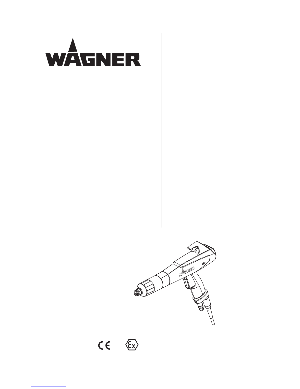
Manual powder spray gun
PEM-X1
Version 03/2014
Translation of the Original
Operating Manual
Page 2

Page 3

3
PEM-X1
OPERATING MANUAL
VERSION 03/2014 ORDER NUMBER DOC 2326020
Table of Contents
1 ABOUT THIS MANUAL 6
1.1 Preface 6
1.2 Warnings, Notices, and Symbols in this Operating Manual 6
1.3 Languages 7
1.4 Abbreviations 7
2 CORRECT USE 8
2.1 Device Type 8
2.2 Type of Use 8
2.3 Use in Potentially Explosive Areas 8
2.4 Safety Parameters 9
2.5 Processible Working Materials 9
2.6 Reasonably Foreseeable Misuse 10
2.7 Residual Risks 10
3 IDENTIFICATION 11
3.1 Explosion Protection Identi cation 11
3.2 Permissible Device Combinations 11
4 GENERAL SAFETY INSTRUCTIONS 12
4.1 Safety Instructions for the Operator 12
4.1.1 Electrical Devices and Equipment 12
4.1.2 Sta Quali cations 12
4.1.3 Safe Work Environment 12
4.2 Safety Instructions for Sta 13
4.2.1 Safe Handling of WAGNER Powder Spray Devices 13
4.2.2 Grounding the Device 13
4.2.3 Product Hoses 13
4.2.4 Cleaning 14
4.2.5 Handling Powder Lacquers 14
4.3 Information About Safe Discharges 15
4.4 Protective and Monitoring Equipment 16
5 DESCRIPTION 17
5.1 Spray Gun Design 17
5.2 Functioning of the Spray Gun 17
5.3 Technical Data 18
5.3.1 Dimensions 19
5.4 Permitted Accessories 20
5.5 Scope of Delivery 20
6 ASSEMBLY AND COMMISSIONING 21
6.1 Training Assembly/Commissioning Sta 21
6.2 Storage Conditions 21
6.3 Installation Conditions 21
6.4 Preparing the Spray Gun 22
6.4.1 Selection of the Suitable Nozzle System 22
6.5 Connecting the Spray Gun 24
6.6 Grounding 26
6.6.1 Grounding the Powder Coating System 27
Page 4

4
PEM-X1
OPERATING MANUAL
VERSION 03/2014 ORDER NUMBER DOC 2326020
Table of Contents
7 OPERATION 28
7.1 Training the Operating Sta 28
7.2 Safety Instructions 28
7.3 Optimizing the Powder Cloud for Your Coating 29
7.3.1 Recommended Settings for Total Air Volume 29
7.4 Switching O the Spray Gun 30
7.5 Adjustment of Powder Quantity 31
7.6 "Double Click" Program (High Dynamic Remote) 32
7.7 Reproducible Setting of the Nozzle Position 33
8 CLEANING AND MAINTENANCE 34
8.1 Cleaning 34
8.1.1 Cleaning Sta 34
8.1.2 Safety Instructions 34
8.1.3 Cleaning Procedures 35
8.2 Maintenance 36
8.2.1 Maintenance Sta 36
8.2.2 Safety Instructions 36
8.2.3 Maintenance Procedures 37
8.2.4 Replacing the Spray Gun 38
8.3 Removing the Fan spray nozzle 39
8.4 Fitting the Fan spray nozzle 40
8.5 Removing the Round spray nozzle 41
8.6 Fitting the Round spray nozzle 42
8.7 Replacing the Protective Wedge 43
8.8 Changing from Fan spray nozzle to Round spray nozzle 45
8.9 Assembly of the CoronaStar 47
8.10 Replacing the Suspension Hook 48
9 INSPECTIONS IN ACCORDANCE WITH DIN EN 500502: 2014 49
9.1 Overview of Inspections 50
10 DISASSEMBLY AND DISPOSAL 51
10.1 Disassembly 51
10.2 Disposal 51
11 TROUBLESHOOTING AND RECTIFICATION 52
12 ACCESSORIES 54
12.1 Fan spray nozzle 54
12.2 De ector Cone 54
12.3 Electrode Holder 54
12.4 Hose Take-up 55
12.5 CoronaStar Retro t Set 55
12.6 Wedge Tool 55
12.7 Nozzle Extension, X1 VL 150/300/500 56
12.8 Nozzle Extension, X1 VL 750 56
12.9 Powder Hose 57
12.10 Gun Connection Cable 57
12.11 Wall Mount 57
12.12 Recipe Sticker 58
12.13 Powder Measuring Adapter 59
Page 5

5
PEM-X1
OPERATING MANUAL
VERSION 03/2014 ORDER NUMBER DOC 2326020
Table of Contents
13 SPARE PARTS 60
13.1 How Can Spare Parts Be Ordered? 60
13.2 PEM-X1 Corona Manual Gun With a Fan spray nozzle 61
13.3 PEM-X1 Corona Manual Gun With a Round spray nozzle 62
13.4 Electrode Holder, X1 R 63
14 DECLARATION OF WARRANTY AND CONFORMITY 64
14.1 Important Notes Regarding Product Liability 64
14.2 Warranty Claim 64
14.3 Declaration of Conformity 65
14.4 EC Type Examination Certi cate 66
14.5 FM Approval 67
Page 6
6
PEM-X1
OPERATING MANUAL
VERSION 03/2014 ORDER NUMBER DOC 2326020
1 ABOUT THIS MANUAL
The operating manual contains information about safely operating, maintaining, cleaning
and repairing the device.
The operating manual is part of the device and must be available to operating and service
sta .
Operating and service sta should be instructed according to the safety instructions.
The device may only be operated in compliance with this operating manual.
This equipment can be dangerous if it is not operated according to the instructions in this
operating manual.
Electrostatic manual coating systems may only be operated by quali ed personnel.
1.1 PREFACE
1.2 WARNINGS, NOTICES, AND SYMBOLS IN THIS OPERATING MANUAL
Warning instructions in this operating manual highlight particular dangers to users and to
the device and state measures for avoiding the hazard. These warning instructions fall into
the following categories:
Danger - immediate risk of danger.
Non-observance will result in death or serious injury.
Warning - possible imminent danger.
Non-observance may result in death or serious injury.
Caution - a possibly hazardous situation. Nonobservance may result in minor injury.
Note - provides information about particular characteristics and how to proceed.
Notice - a possibly hazardous situation.
Non-observance may result in damage to property.
This notice warns you of a hazard!
Possible consequences of not observing the warning instructions.
The signal word indicates the hazard level.
The measures for preventing the danger and its consequences.
DANGER
This notice warns you of a hazard!
Possible consequences of not observing the warning instructions.
The signal word indicates the hazard level.
The measures for preventing the danger and its consequences.
WARNING
This notice warns you of a hazard!
Possible consequences of not observing the warning instructions.
The signal word indicates the hazard level.
The measures for preventing the danger and its consequences.
CAUTION
This notice warns you of a hazard!
Possible consequences of not observing the warning instructions. The signal word
indicates the hazard level.
The measures for preventing the danger and its consequences.
NOTICE
Page 7
7
PEM-X1
OPERATING MANUAL
VERSION 03/2014 ORDER NUMBER DOC 2326020
1.3 LANGUAGES
The operating manual is available in the following languages:
German 2326019 English 2326020
French 2326021 Italian 2326022
Spanish 2326023 Russian 2333344
Chinese 2333345 Dutch 2337552
Swedish 2345951 Hungarian 2341080
Portuguese 2345347 Danish 2348202
Finnish 2348203 Norwegian 2348238
1.4 ABBREVIATIONS
Number of pieces
Position
Marking in the spare parts lists
Order No. Order number
Spare part
Page 8
8
PEM-X1
OPERATING MANUAL
VERSION 03/2014 ORDER NUMBER DOC 2326020
2 CORRECT USE
2.1 DEVICE TYPE
Powder spray guns for manual coating of grounded work pieces
2.2 TYPE OF USE
The PEM-X1 manual powder spray gun is designed for the electrostatic coating of work
pieces with organic powders. Any other form of use is considered non-intended use.
Wagner disclaims liability for any damage resulting from non-intended use.
Electrostatic manual coating systems may only be used in spray areas equipped in
accordance with EN 12981 or under equivalent ventilation conditions.
2.3 USE IN POTENTIALLY EXPLOSIVE AREAS
In explosion hazard areas, only use approved explosion-proof electrical devices.
This type A-P electrostatic powder spray gun is suitable for processing industrial powder
paints for coating electrically conductive objects and can be used in potentially explosive
areas (zone 22). (See Chapter 3.1 Explosion Protection Identi cation).
Page 9
9
PEM-X1
OPERATING MANUAL
VERSION 03/2014 ORDER NUMBER DOC 2326020
2.4 SAFETY PARAMETERS
WAGNER accepts no liability for any damage arising from non-intended use.
Electrostatic manual coating systems may only be operated in an undamaged condition.
Damaged devices must be decommissioned immediately and repaired immediately.
Use the device only to work with the products recommended by WAGNER.
Operate only the device as a whole.
Do not deactivate safety xtures.
Spare parts and accessories may have safety-relevant properties.
Use only WAGNER original spare parts and accessories.
The manual powder spray gun may only be operated under the following conditions if:
the operating sta have previously been trained on the basis of this operating manual,
the safety regulations listed in this operating manual are observed,
the operating, maintenance and repair information in this operating manual is observed,
and the statutory requirements and accident prevention regulations standards in the
country of use are observed.
2.5 PROCESSIBLE WORKING MATERIALS
Types of powder which can be charged electrostatically
Metallic powder
Page 10

10
PEM-X1
OPERATING MANUAL
VERSION 03/2014 ORDER NUMBER DOC 2326020
2.6 REASONABLY FORESEEABLE MISUSE
2.7 RESIDUAL RISKS
Residual risks are risks which cannot be excluded even in the event of correct use.
If necessary, warning and prohibition signs at the relevant points of risk indicate residual
risks.
The following is prohibited:
coating work pieces which are not grounded,
unauthorized conversions and modi cations to the spray gun,
processing liquid or similar coating products,
using defective components, spare parts, or accessories other than those described in
Chapter 12 of this operating manual.
The forms of misuse listed below may result in physical injury or property damage:
Use of damp powder lacquer
Incorrectly set values for powder discharge
Incorrectly set electrostatic values
Use of defective components and accessories
Use for foodstu s
Use in the pharmaceutical sector
Use with non-authorized control units
Residual risk Source Consequences Speci c measures Lifecycle phase
Skin contact with
powder lacquers
and cleaning agents
Handling powder
lacquers and
cleaning agents
Skin irritation,
allergies
Wear protective
clothing,
Operation,
observe safety data
sheets
maintenance,
disassembly
Powder lacquer
in air outside the
de ned working
area
Lacquering outside
the de ned working
area
Inhalation of
substances
hazardous to health
Observe working
and operating
instructions
Operation,
maintenance
Page 11
11
PEM-X1
0102
OPERATING MANUAL
VERSION 03/2014 ORDER NUMBER DOC 2326020
3 IDENTIFICATION
3.1 EXPLOSION PROTECTION IDENTIFICATION
The EC type examination certi cate PTB 12 ATEX 5002 can be found in Chapter 14.4.
3.2 PERMISSIBLE DEVICE COMBINATIONS
Gun type: PEM-X1
Manufacturer: J. Wagner AG
CH - 9450 Altstätten
II 2 D 2mJ 85 °C
CE: European Communities
0102: Number of noti ed body which issues the recognition of quality
assurance in production
Ex: Symbol for explosion protection
II: Device class II
2: Category 2
D: Ex-atmosphere dust
2mJ: Maximum ignition energy 2 mJ
85 °C: Maximum surface temperature
Incorrect use!
Risk of injury and damage to the device.
Only connect original Wagner devices to the PEM-X1 powder
spray gun.
WARNING
The PEM-X1 powder spray gun may only be connected to the control devices listed below:
EPG-Sprint X with the corresponding PI-F1/HiCoat ED-F powder injector
EPG-Sprint with the corresponding PI-F1/HiCoat ED-F powder injector*
EPG S2 with the corresponding PI-F1/HiCoat ED-F powder injector*
* The remote control function of the PEM-X1 spray gun is not available when using these
control units.
Permissible device combinations for the USA and Canada, see Chapter 14.5 "FM Approval".
Page 12
12
PEM-X1
OPERATING MANUAL
VERSION 03/2014 ORDER NUMBER DOC 2326020
4 GENERAL SAFETY INSTRUCTIONS
4.1 SAFETY INSTRUCTIONS FOR THE OPERATOR
4.1.1 ELECTRICAL DEVICES AND EQUIPMENT
4.1.2 STAFF QUALIFICATIONS
4.1.3 SAFE WORK ENVIRONMENT
Keep this operating manual at hand near the device at all times.
Always follow local regulations concerning occupational safety and accident
prevention.
To be provided in accordance with the local safety requirements with regard to the
operating mode and ambient in uences.
May only be maintained by skilled electricians.
Must be operated in accordance with the safety regulations and electrotechnical
regulations.
Must be repaired immediately in the event of problems.
Must be decommissioned if they pose a hazard.
Must be de-energized before work is commenced on active parts.
Secure the device against being switched back on without authorization. Inform sta
about planned work.
Observe electrical safety regulations.
The oor in the working area must be electrostatically conductive (measurements
according to EN 1081 and EN 61340-4-1).
The footwear worn by the operators must comply with the requirements of
EN ISO 20344. The measured insulation resistance must not exceed 100 MΩ (megaohms).
The protective clothing, including gloves, must comply with the requirements of
EN ISO 1149-5. The measured insulation resistance must not exceed 100 MΩ
(megaohms).
The powder release must be electrically interlocked with the powder spray system's
exhaust air equipment.
Excess coating product (overspray) must be collected up safely.
Ensure that there are no ignition sources such as naked ames, sparks, glowing wires,
or hot surfaces in the vicinity. Do not smoke.
Maintain su cient quantities of suitable re extinguishers and ensure that they are
serviceable.
The operating company must ensure that an average concentration of powder lacquer
in the air does not exceed 50% of the lower explosion limit (LEL = max. permitted
concentration of powder to air). If no reliable LEL value is available, the average
concentration must not exceed 10 g/m³.
Ensure that the device is operated, maintained and repaired only by trained persons.
Page 13
13
PEM-X1
OPERATING MANUAL
VERSION 03/2014 ORDER NUMBER DOC 2326020
4.2.1 SAFE HANDLING OF WAGNER POWDER SPRAY DEVICES
4.2.2 GROUNDING THE DEVICE
4.2.3 PRODUCT HOSES
4.2 SAFETY INSTRUCTIONS FOR STAFF
Only use an original Wagner powder hose.
Always follow the information in this manual, particularly the general safety instructions
and the warning instructions.
Always follow local regulations concerning occupational safety and accident
prevention.
Under no circumstances may people with pacemakers enter the area where the
high-voltage eld between the spray gun and the work piece to be coated builds up!
Do not point spray guns at people.
Before all work on the device, in the event of work interruptions and functional faults:
- Switch o the energy/compressed air supply.
- Secure the spray gun against actuation.
- Relieve pressure on spray gun and device.
- In case of functional faults: Identify and correct the problem, proceed as described in
the "Fault Recti cation" chapter.
The electrostatic charge may, in certain cases, give rise to electrostatic charges on the
device. This may result in the formation of sparks or ames when discharging.
Ensure that the device is grounded before each coating process.
All the system's conductive elements, such as oors, walls, ceilings, protective
grating, transport equipment, work pieces, powder tanks, automatic moving devices
or construction parts etc. in the spray area, with the exception of parts which carry
high-voltage during operation, must be connected to the grounding system.
Parts of the booth must be grounded in accordance with EN 12981.
Ensure that all persons inside the working area are grounded, e.g., by wearing
electrostatically conductive shoes.
The functionality of grounding cables must be checked regularly (see EN 60204).
Page 14
14
PEM-X1
OPERATING MANUAL
VERSION 03/2014 ORDER NUMBER DOC 2326020
4.2.5 HANDLING POWDER LACQUERS
4.2.4 CLEANING
Before starting cleaning or any other manual work, the high-voltage in the spray area
must be shut down and locked to prevent it from being switched back on.
Lock the compressed air supply and decompress the device.
Secure the device against being switched back on without authorization.
Use only electrically conducting and grounded tanks for cleaning uids.
Preference should be given to non- ammable cleaning uids.
Flammable cleaning liquids may only be used if, after switching o the high-voltage,
all high-voltage conducting parts are discharged to a discharge energy of less than
0.24mJ before they can be accessed.
Most ammable solvents have an ignition energy of around 0.24 mJ or 60 nC.
The cleaning agent's ash point must be at least 15 K above the ambient temperature.
Only mobile industrial vacuum cleaners of design 1 (see EN 60335-2) may be used to
remove dust deposits.
When preparing or processing the powder and cleaning the device, take note of the
processing regulations, laid down by the manufacturer of the powder lacquers, being
used.
Take note of the manufacturer’s instructions and the relevant environmental protection
regulations when disposing of powder lacquers.
Take the prescribed safety measures, in particular the wearing of safety glasses and
safety clothing as well as the use of protective hand cream.
Use a mask or breathing apparatus if necessary.
To ensure su cient protection of health and the environment, only operate the device
in a powder booth or on a spray wall with activated ventilation (exhaust air).
Page 15
15
PEM-X1
P_01698
OPERATING MANUAL
VERSION 03/2014 ORDER NUMBER DOC 2326020
4.3 INFORMATION ABOUT SAFE DISCHARGES
With the high-voltage switched on, a luminous or corona discharge occurs at the electrode
tip; this can only be seen in the dark. This physical e ect can be seen when the electrode
is brought near the grounded work piece. This luminous discharge does not involve any
ignition energy and has no e ect on system handling. When the electrode approaches the
work piece, the control unit automatically reduces the high-voltage to a safe value. If you
touch plastic parts of the spray gun with your nger, harmless discharges may occur due to
the high-voltage eld around the spray gun (so-called brush discharges). However, these
do not contain any ignition energy.
Work piece
Luminous discharge
Nozzle
Electrode
Page 16

16
PEM-X1
OPERATING MANUAL
VERSION 03/2014 ORDER NUMBER DOC 2326020
4.4 PROTECTIVE AND MONITORING EQUIPMENT
To prevent electrostatic ashover, the union nut for securing the nozzles is designed in a
certain geometric shape.
This shape, together with the shape of the fan spray nozzle or de ector cone sleeve,
prevents the nozzles from coming loose unintentionally (see Chapters 8.3, 8.5, 8.8).
To ensure safety, only use genuine Wagner spare parts!
Incorrect use!
Risk of injury and damage to the device.
Protective and monitoring equipment must not be removed,
modi ed or rendered unusable.
Regularly check for perfect functioning.
If defects are detected on protective and monitoring equipment,
the system must not be operated until these defects are
remedied.
WARNING
Page 17
17
PEM-X1
A
B
C
K
I
F
P_01663
E
D
G
F
L
H
OPERATING MANUAL
VERSION 03/2014 ORDER NUMBER DOC 2326020
5 DESCRIPTION
5.1 SPRAY GUN DESIGN
Designation
Suspension hook
Handle
Electrical connection cable
Powder hose connection
Trigger lever
Union nut
Round spray nozzle
Atomizing air connection
Fan spray nozzle
Buttons to adjust the powder quantity
Spray gun body
5.2 FUNCTIONING OF THE SPRAY GUN
High-voltage is activated in the manual gun when the trigger is actuated!
The powder supply and air supply to the gun are activated at the same time.
The control unit must be switched o in order to lock the spray gun.
To prevent electrostatic ashover, the union nut for securing the nozzles is designed with
a labyrinth.
Page 18
18
PEM-X1
OPERATING MANUAL
VERSION 03/2014 ORDER NUMBER DOC 2326020
Dimensions:
Length/width/height see Chapter 5.3.1
Weight 490 g; 1.08 lbs
Electrical:
Input voltage maximum 22 Vpp
Input current maximum 0.9 A
Frequency 19 - 30 kHz
Output voltage maximum 100 kV DC
Maximum Corona current 120 μA
Polarity negative
Construction type in accordance with EN 50050-2
Protection class
Pneumatic:
Input air pressure (atomizing air volume) maximum 3 bar; 0.3 MPa, 43.51 psi
Powder output quantity maximum 450 g/min;
maximum 0.99 lbs/min
Ambient conditions:
Operating temperature range 5 - 45 °C; 41 - 113 °F
Relative humidity
5.3 TECHNICAL DATA
Ambient conditions:
If low-melting powders are used, the ambient temperature may have to be lower than
30 °C; 86 °F.
Volume measures:
for volumes speci ed in Nm³ (standard cubic meters). One cubic meter of a gas at 0 °C and
1.013 bar is called norm cubic meter.
Outgoing air containing oil!
Risk of poisoning if inhaled.
Insu cient paint application quality.
Provide compressed air free from oil and water
(Quality Standard 3.5.2 according to ISO 8573.1)
3.5.2 = 5 μm / +7 °C; 44.6 °F / 0.1 mg/m³.
WARNING
Page 19
19
PEM-X1
A
P_01662
B
C
OPERATING MANUAL
VERSION 03/2014 ORDER NUMBER DOC 2326020
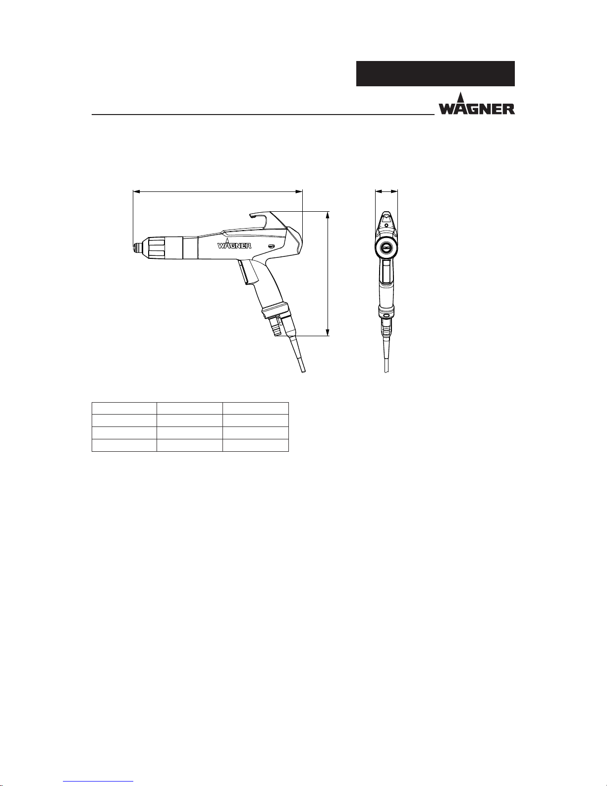
5.3.1 DIMENSIONS
Measurement mm inch
A* 335/349 13.19/13.74
B 248 9.76
C 45 1.77
* with fan spray nozzle/with de ector cone
Page 20
20
PEM-X1
OPERATING MANUAL
VERSION 03/2014 ORDER NUMBER DOC 2326020
Stk Order No. Designation
1 2322587 PEM-X1 manual gun with a fan spray nozzle
2335844 PEM-X1 manual gun with a round spray nozzle
1
Nozzle set
The standard equipment includes:
1 2326024 Declaration of conformity
1 2326019 Operating manual, German
1 see Chapter 1.3 Operating manual in local language
5.5 SCOPE OF DELIVERY
5.4 PERMITTED ACCESSORIES
Only the accessories listed in the "Accessories" chapter of this operating manual may be
connected to the PEM-X1 powder spray gun.
The accessories listed in the "Accessories" chapter were included in the EC type examination
and are approved for use with the gun.
Page 21
21
PEM-X1
OPERATING MANUAL
VERSION 03/2014 ORDER NUMBER DOC 2326020
6 ASSEMBLY AND COMMISSIONING
6.1 TRAINING ASSEMBLY/COMMISSIONING STAFF
Incorrect installation/operation!
Risk of injury and damage to the device.
The commissioning sta must have the technical skills to safely
undertake commissioning.
The commissioning sta must be familiar with the provisions of
European standard DIN EN 50050-2.
When commissioning and for all work, read and follow the
operating manual and safety regulations for the additionally
required system components.
WARNING
6.2 STORAGE CONDITIONS
Until the point of assembly, the powder spray gun must be stored in a dry location, free
from vibrations and with a minimum of dust. The powder spray gun must be stored in
closed rooms.
The air temperature at the storage location must be between 5 - 45 °C; 41 - 113 °F.
The relative air humidity at the storage location must not exceed 75%.
6.3 INSTALLATION CONDITIONS
The air temperature at the assembly site must be between 5 - 45 °C; 41 - 113 °F.
Depending on the powder lacquer used, the maximum permissible ambient temperature
for reliable operation can be signi cantly below +40 °C; 104 °F.
The relative air humidity at the assembly location must not exceed 75%.
Page 22
22
PEM-X1
P_01664
P_01664
P_01665
P_02209
OPERATING MANUAL
VERSION 03/2014 ORDER NUMBER DOC 2326020
6.4 PREPARING THE SPRAY GUN
6.4.1 SELECTION OF THE SUITABLE NOZZLE SYSTEM
Nozzle Application Distance to
work piece
Powder output
(mm) (g/min)
Universal
120 ... 300 50 ... 300
Deep and complex part
geometries
Extensive work pieces
The spray width can be adjusted by the sliding ring.
Rear sliding ring
Wide cloud
Cloud opening angle approx. 80°
Front sliding ring, front
Narrow cloud
Cloud opening angle approx. 60°
Front sliding ring, front, turned by 90°
Extra narrow cloud
Cloud opening angle approx. 40°
Nozzle Application overview Powder cloud
Fan spray nozzle Complex part geometries Widely spread at powder cloud
Flat work pieces
(reduced picture frame)
Pro les
Undercuts
De ector cone Round powder cloud:
Wire goods Size of the powder cloud is
dependent on the de ector plate
diameter
Grid designs
Small components
The process of changing from the fan spray nozzle to the de ector cone is described in
Chapter 8.8 "Changing from Fan spray nozzle to Round spray nozzle".
You will nd the article numbers of the di erent nozzles in Chapter 12 "Accessories".
Page 23

23
PEM-X1
P_01665
P_01666
P_01667
OPERATING MANUAL
VERSION 03/2014 ORDER NUMBER DOC 2326020
De ector cone Application Distance to work piece
(mm)
R18
100 ... 300
18 mm
Smaller at parts
R25
100 ... 300
25 mm
Medium sized at parts
R34
100 ... 300
34 mm
Large at parts
Output quantity [g/min]
Overall air
Feed air [%] 4.00 Nm³/h 5.00 Nm³/h 6.00 Nm³/h
50 140 170 210
60 200 240 260
70 250 270 300
80 300 320 350
90 330 360 380
100 370 400 420
The values have been determined by means of an PI-F1 injector and a powder hose
11mm,
length 5m.
These values have to be considered as reference values and depend on the characteristics
of the powder and the status of the transport relevant pieces (e.g., injector).
Page 24

24
PEM-X1
OPERATING MANUAL
VERSION 03/2014 ORDER NUMBER DOC 2326020
Procedure:
1. Switch o the high-voltage generation on the control unit.
2. Before connecting the spray gun, check that all components (such as the nozzle system
and union nut) are correctly tted.
3. Connect electrical cable of spray gun to control unit.
4. Connect the powder feed hose to the spray gun and to the powder injector.
5. Connect the atomizing air hose to the spray gun and to the control unit.
6.5 CONNECTING THE SPRAY GUN
Unintentional putting into operation!
Risk of injury.
Before any work on the device, in the event of work interruptions
and malfunctions:
Switch o the energy/compressed air supply.
Relieve spray gun and device pressure.
Secure the spray gun against actuation.
In the event of malfunctions, remedy the fault as described in
the "Troubleshooting" chapter.
WARNING
Page 25

25
PEM-X1
P_01668
I
O
OPERATING MANUAL
VERSION 03/2014 ORDER NUMBER DOC 2326020
to the electrical connection on the control unit
Powder feed from the powder injector
Atomizing air from control unit
Powder spray gun
Control unit
Powder injector
red
blue
transparent
Page 26

26
PEM-X1
OPERATING MANUAL
VERSION 03/2014 ORDER NUMBER DOC 2326020
6.6 GROUNDING
No Grounding!
Risk of explosion and risk of electric shock.
Electrostatic control units and the associated spray equipment
may only be connected to mains supplies with a protective
conductor connection (PE conductor)!
DANGER
Heavy powder mist if grounding is insu cient!
Danger of poisoning.
Insu cient paint application quality.
Ground all device components.
Ground the work pieces to be coated.
WARNING
For safety reasons, the control unit must be properly grounded. The ground connection
to the energy supply (socket) takes the form of the mains connection cable's protective
conductor, while that to the work piece / system is via the knurled screw on the rear of the
control unit. Both connections are absolutely essential. If installed correctly as described
above, the spray gun is grounded via the gun cable between the control unit and spray
gun.
Good grounding of the work piece is also necessary for optimum powder coating.
A poorly grounded work piece causes:
dangerous electric charging of the work piece,
very poor wrap-around,
uneven coating,
back spraying to the spray gun, i.e. contamination.
Prerequisites for perfect grounding and coating are:
Clean work piece suspension.
Grounding of spray booth, conveyor system and suspension on the building side in
accordance with the operating manuals or the manufacturer's information.
Grounding of all conductive parts within the working area.
The grounding resistance of the work piece may not exceed 1 MΩ (megohm).
(Resistance to ground measured at 500 V or 1,000 V).
Page 27

27
PEM-X1
P_01120
1
2
3
6
7
5
4
OPERATING MANUAL
VERSION 03/2014 ORDER NUMBER DOC 2326020
6.6.1 GROUNDING THE POWDER COATING SYSTEM
The footwear worn by the operators must comply with the requirements of EN ISO 20344.
The measured insulation resistance must not exceed 100 MΩ (megohms).
The protective clothing, including gloves, must comply with the requirements of
ENISO 1149-5. The measured insulation resistance must not exceed 100 MΩ (megohms).
Sparks between conveyor, conveyor hooks (hangers) and work piece can occur
if electric contact points between conveyor, conveyor hooks (hangers) and work
piece are not su ciently cleaned and therefore the work pieces are not su ciently
grounded!
These sparks can cause heavy radio frequency interference (EMC).
1 Only use mains cables with grounding strand!
2 Connect grounding cable with booth and signal ground!
3 Connect grounding cable to an uncoated metal part of the booth!
4 All paint must be removed from hook and other hanger parts!
5 Wear electrostatically conductive gloves!
6 Wear electrostatically conductive footwear!
7 The oor must be electrostatically conductive!
Page 28

28
PEM-X1
OPERATING MANUAL
VERSION 03/2014 ORDER NUMBER DOC 2326020
7 OPERATION
7.1 TRAINING THE OPERATING STAFF
7.2 SAFETY INSTRUCTIONS
Incorrect operation!
Risk of injury and damage to the device.
The operating sta must be quali ed to operate the entire system.
Before work commences, the operating sta must receive
appropriate system training.
The operating sta must be familiar with the provisions of
European standard DIN EN 50050-2.
WARNING
Incorrect operation!
Risk of injury and damage to the device.
If contact with powder products or cleaning agents causes skin
irritation, appropriate precautionary measures must be taken,
e.g., wearing protective clothing.
The footwear worn by operating sta must comply with
EN ISO 20344. The measured insulation resistance must not
exceed 100 megohms.
The protective clothing, including gloves, must comply with
EN ISO 1149-5. The measured insulation resistance must not
exceed 100 megohms.
WARNING
Page 29

29
PEM-X1
OPERATING MANUAL
VERSION 03/2014 ORDER NUMBER DOC 2326020
Procedure:
1. Switch on the high-voltage generation and the powder feed.
Note:
To minimize wear on the wearing parts, the total air volume should be below 5 Nm³/h!
The atomizing air should be adjusted for the:
fan spray nozzle to 0.1 Nm³/h,
round spray nozzle to > 0.2 Nm³/h
2. Adjust the powder quantity and the powder speed on a test piece.
7.3 OPTIMIZING THE POWDER CLOUD FOR YOUR COATING
7.3.1 RECOMMENDED SETTINGS FOR TOTAL AIR VOLUME
Hose diameter
Hose length 9 mm 10 mm 11 mm 12 mm
4 - 8 m 2.0 - 2.5 m³/h 3.0 - 3.5 m³/h 4.0 - 4.5 m³/h
8 - 12 m 2.5 - 3.0 m³/h 3.5 - 4.0 m³/h 4.5 - 5.0 m³/h
12 - 16 m 3.0 - 3.5 m³/h 4.0 - 4.5 m³/h 5.0 - 5.5 m³/h
Page 30

30
PEM-X1
OPERATING MANUAL
VERSION 03/2014 ORDER NUMBER DOC 2326020
7.4 SWITCHING OFF THE SPRAY GUN
By releasing the trigger the powder feed is stopped and the high-voltage switched o .
To safely switch o the spray gun, e.g., for maintenance work, the control unit must be
switched o .
Page 31

31
PEM-X1
P_01669
OPERATING MANUAL
VERSION 03/2014 ORDER NUMBER DOC 2326020
7.5 ADJUSTMENT OF POWDER QUANTITY
LED display green
Reduce powder quantity
Increase powder quantity
LED display Operation mode
Flashing Normal operation of gun
Constant blinking Activated program has been changed using the "+" or
"-" button.
By selecting another program the modi ed values of
the powder quantity are not taken over, however, the
current values of the other program are taken over
and the blinking changes to ashing.
By saving these settings the current values of the
powder feed are taken over in the current program.
The blinking changes back to ashing.
By activating the "Double Click" function the blinking
is switched o as well, the preset program values are
then active again.
Permanent lighting Trigger has been actuated with "Double Click", i.e., the
"Double Click" program is activated.
Note:
This function can only be activated in combination with the EPG-Sprint X control unit.
By pressing the buttons "+/-" the preset program values of the feed air (powder quantity)
can be changed in the desired direction.
In this case the total air remains unchanged, the feed and dosing air is readjust accordingly.
Page 32

32
PEM-X1
2x
P_01701
2x
2x
kV
80
60
40
20
100
Tri Cor
5
4
3
2
1
120
80
40
20
10
μA
2x
2x
kV
80
60
40
20
100
Tri Cor
5
4
3
2
1
120
80
40
20
10
μA
2x
2x
kV
80
60
40
20
100
Tri Cor
5
4
3
2
1
120
80
40
20
10
μA
OPERATING MANUAL
VERSION 03/2014 ORDER NUMBER DOC 2326020
7.6 "DOUBLE CLICK" PROGRAM HIGH DYNAMIC REMOTE
This function is used to change quickly to another program during a coating operation.
The operator can access a previously set program by double-clicking on the trigger lever
on the spray gun, for example to recoat parts using di erent parameters (high-voltage,
current limitation, air volumes etc.).
To access the function, press the trigger lever on the spray gun twice in quick succession
and hold down. Upon releasing the trigger, the original program will be returned to.
Page 33

33
PEM-X1
P_01671
OPERATING MANUAL
VERSION 03/2014 ORDER NUMBER DOC 2326020
7.7 REPRODUCIBLE SETTING OF THE NOZZLE POSITION
An adjustment tool is provided for the fan spray nozzle.
It permits turning the fan spray nozzle without
damaging the electrodes and without removing the
union nut.
The union nut only has to be slackened.
Page 34

34
PEM-X1
OPERATING MANUAL
VERSION 03/2014 ORDER NUMBER DOC 2326020
8 CLEANING AND MAINTENANCE
Cleaning work should be undertaken regularly and carefully by quali ed and trained sta .
The sta must be familiar with the DIN EN 50050-2 provisions. They should be informed of
speci c hazards during their training.
The following hazards may arise during cleaning work:
Health hazard from inhaling powder lacquer
Use of unsuitable cleaning tools and aids
8.1 CLEANING
8.1.2 SAFETY INSTRUCTIONS
8.1.1 CLEANING STAFF
Explosive powder/air mixes!
Danger to life and damage to the device.
Before starting cleaning or other manual work, the high-voltage
must be shut down and locked to prevent it from being switched
back on!
The spray gun must be separated from the high-voltage supply
and compressed air supply before any cleaning work is started!
Use only electrically conductive tanks for cleaning liquids!
Ground the tank!
Preference should be given to non- ammable cleaning uids.
Flammable cleaning liquids may only be used if, after switching
o the high-voltage, all high-voltage conducting parts are
discharged to a discharge energy of less than 0.24 mJ before
they can be accessed.
Most ammable solvents have an ignition energy of around
0.24 mJ or 60 nC.
The cleaning agent's ash point must be at least 15 K above the
ambient temperature.
Only mobile industrial vacuum cleaners of design 1 (see EN 60335-2)
may be used to remove dust deposits.
DANGER
Page 35

35
PEM-X1
OPERATING MANUAL
VERSION 03/2014 ORDER NUMBER DOC 2326020
The cleaning intervals should be adapted by the operator depending on the level of use
and if necessary the level of soiling.
If in doubt, we recommend contacting J. Wagner AG's specialist personnel.
The valid health and safety speci cations and the safety instructions provided in Chapter 4
must be adhered to for all cleaning work.
8.1.3 CLEANING PROCEDURES
Incorrect maintenance!
Risk of injury and damage to the device.
If contact with powder products or cleaning agents causes skin
irritation, appropriate precautionary measures must be taken,
e.g., wearing protective clothing.
The footwear worn by operating sta must comply with
EN ISO 20344. The measured insulation resistance must not exceed
100 megohms.
The protective clothing, including gloves, must comply with
EN ISO 1149-5. The measured insulation resistance must not
exceed 100 megohms.
WARNING
Page 36

36
PEM-X1
OPERATING MANUAL
VERSION 03/2014 ORDER NUMBER DOC 2326020
8.2 MAINTENANCE
Maintenance work should be undertaken regularly and carefully by quali ed and trained
sta . They should be informed of speci c hazards during their training.
The following hazards may arise during maintenance work:
Health hazard from inhaling powder lacquer
Use of unsuitable tools and aids
Once the maintenance work is complete, the device must be checked by a quali ed person
to ensure a reliable condition.
8.2.1 MAINTENANCE STAFF
8.2.2 SAFETY INSTRUCTIONS
Incorrect maintenance/repair!
Risk of injury and damage to the device.
Have repairs and part replacements carried out only by specially
trained sta or a WAGNER service center.
Before all work on the device and in the event of work
interruptions:
- Switch o the energy/compressed air supply.
- Relieve spray gun and device pressure.
- Secure the spray gun against actuation.
Observe the operating manual and service manuals at all times
when carrying out work.
DANGER
Incorrect maintenance/repair!
Danger to life and damage to the device.
Repair or replacement of devices or parts of devices are only
allowed to be performed outside the hazard area by quali ed
personnel.
Before starting maintenance or other manual work, the high-
voltage must be shut down and locked to prevent it from being
switched back on!
The spray gun must be separated from the high-voltage supply
and compressed air supply before any maintenance work is
started!
DANGER
Page 37

37
PEM-X1
OPERATING MANUAL
VERSION 03/2014 ORDER NUMBER DOC 2326020
The maintenance intervals should be adapted by the operator depending on the level of
use and if necessary the level of soiling.
If in doubt, we recommend contacting J. Wagner AG's specialist personnel.
The valid health and safety speci cations and safety instructions provided in Chapter 4
must be adhered to for all maintenance work.
Maintenance work Point in time
per shift weekly
Blow out gun and check for sintering
Check gun settings
Check gun discharge pressure
Blow out powder hoses
Check grounding
Check compressed air quality
Check gun voltage
Check powder hoses for bends and sintering
8.2.3 MAINTENANCE PROCEDURES
Incorrect maintenance!
Risk of injury and damage to the device.
If contact with powder products or cleaning agents causes skin
irritation, appropriate precautionary measures must be taken,
e.g., wearing protective clothing.
The footwear worn by operating sta must comply with
EN ISO 20344. The measured insulation resistance must not
exceed 100 megohms.
The protective clothing, including gloves, must comply with
EN ISO 1149-5. The measured insulation resistance must not
exceed 100 megohms.
WARNING
Page 38

38
PEM-X1
5
4
3
2
1
P_01672
OPERATING MANUAL
VERSION 03/2014 ORDER NUMBER DOC 2326020
8.2.4 REPLACING THE SPRAY GUN
Before replacing the spray gun, any powder residue must be thoroughly removed.
The wearing parts in the spray gun, marked in the spare parts list with "
", must be regularly
checked and, if necessary replaced.
Procedure:
1. Switch o control unit.
2. Disconnect electrical cable 1 from control unit 2.
3. Disconnect powder feed hose 3 and atomizing air hose 4 from spray gun 5.
4. Connect powder feed hose 3 and atomizing air hose 4 to the new spray gun 5.
5. Connect electrical cable 1 to control unit 2.
6. Switch on the control unit.
7. The spray gun is ready for use again.
Page 39

39
PEM-X1
1.
2.
P_01673
3.
OPERATING MANUAL
VERSION 03/2014 ORDER NUMBER DOC 2326020
8.3 REMOVING THE FAN SPRAY NOZZLE
3. The parts can be separated by gently pressing the sliding
ring on the fan spray nozzle.
4. Remove powder residues from the parts removed and from
the spray gun.
Note:
Never place the spray gun or parts of the spray gun in cleaning
agent.
As a rule the protective wedge needs to be checked for wear and
replaced if necessary.
Procedure:
1. Unscrew union nut from gun housing.
2. Take union nut with nozzle system o gun body.
The nozzle system remains inserted in the union nut.
Note:
If the nozzle system doesn't remain inserted in the union nut, the
nozzle system and union nut must be replaced.
Page 40

40
PEM-X1
2.
4.
3.
P_01674
OPERATING MANUAL
VERSION 03/2014 ORDER NUMBER DOC 2326020
8.4 FITTING THE FAN SPRAY NOZZLE
4. Screw union nut onto gun housing until fan spray nozzle
can no longer be turned by hand.
Procedure:
Note:
1. Before inserting the electrode holder, the spring contact
of the gun body and contact surface of the electrode
holder should be checked. The spring contact must be
clean and smooth-running, the gun body must also be
clean and free of powder deposits.
2. Insert electrode holder into gun housing.
3. Attach fan spray nozzle to electrode holder and attach
union nut.
Page 41

41
PEM-X1
1.
3.
P_01677
2.
4.
OPERATING MANUAL
VERSION 03/2014 ORDER NUMBER DOC 2326020
8.5 REMOVING THE ROUND SPRAY NOZZLE
Procedure:
1. Pull o de ector cone.
2. Unscrew union nut from gun housing.
3. Take union nut with nozzle system o gun
body. The nozzle system remains inserted in
the union nut.
Note:
If the nozzle system doesn't remain inserted in the
union nut, the nozzle system and union nut must
be replaced.
4. Press nozzle system out of union nut by gently
pressing on de ector cone sleeve.
5. Remove powder residues from the parts
removed and from the spray gun.
Note:
Never place the spray gun or parts of the spray gun
in cleaning agent.
As a rule the protective wedge needs to be checked
for wear and replaced if necessary.
Page 42

42
PEM-X1
2.
P_01678
3.
4.
5.
6.
OPERATING MANUAL
VERSION 03/2014 ORDER NUMBER DOC 2326020
8.6 FITTING THE ROUND SPRAY NOZZLE
Procedure:
Note:
1. Before inserting the electrode holder, the spring
contact of the gun body and contact surface of
the electrode holder should be checked.
The spring contact must be clean and smoothrunning, the gun body must also be clean and
free of powder deposits.
2. Attach de ector cone sleeve onto electrode holder.
3. Insert electrode holder into gun housing.
4. Slide union nut onto gun housing.
5. Screw union nut onto gun housing (hand-tight).
6. Slide de ector cone over de ector cone sleeve.
Page 43

43
PEM-X1
P_01675
2.
1.
3.
2
3
1
E
A
OPERATING MANUAL
VERSION 03/2014 ORDER NUMBER DOC 2326020
8.7 REPLACING THE PROTECTIVE WEDGE
1 Wedge tool
2 Electrode holder (shown with a cut-away
view to improve comprehension)
3 Protective wedge (when positioned)
Procedure:
1. Guide wedge tool 1 into electrode holder2
up to stop.
3. Press protective wedge 3 sideways out of
wedge tool 1 manually (without tool).
Note:
A wedge tool is available to prevent the protective wedge from being damaged when
dismantling and inserting.
The wedge tool has a removal side (E) and an attachment side (A). Use the right side for the
corresponding procedure!
You will nd the necessary wearing parts and spare parts in Chapter 13 "Spare Parts" of this
operating manual.
2. Pull protective wedge 3 out of electrode
holder 2 using wedge tool 1.
Page 44

44
PEM-X1
Y
X
P_01676
3.
1.
2.
OPERATING MANUAL
VERSION 03/2014 ORDER NUMBER DOC 2326020
Procedure:
1. Guide protective wedge 2 into wedge tool 1.
2. Insert both parts into opening on electrode
holder up to stop.
If it is not possible to push the wedge tool in
as far as the X mark, rotate the wedge tool a
little until it can be pushed up to the mark.
The mark X must be ush with the Y end of the
electrode holder.
3. The protective wedge is now correctly
assembled and the wedge tool can be pulled
out of the electrode holder.
4. The protective wedge remains inserted in the
electrode holder.
Prior to re- tting, check whether the contact
points on electrode holder 3 and in gun
housing 5 have been thoroughly cleaned so
that the electrode tip is electrically connected
to the high-voltage generator.
5. Mount fan or round spray nozzle with the
corresponding electrode holder.
Note:
The same wedge tool is used to insert the protective wedge.
Page 45

45
PEM-X1
1.
4.
2.
3.
P_01679
OPERATING MANUAL
VERSION 03/2014 ORDER NUMBER DOC 2326020
The standard Corona spray gun is delivered with a fan spray nozzle. The nozzle can be
changed easily, as described below.
The X1 R electrode holder is necessary to perform the change.
8.8 CHANGING FROM FAN SPRAY NOZZLE TO ROUND SPRAY NOZZLE
Procedure:
1. Unscrew union nut from gun housing.
2. Take union nut with nozzle system o gun body. The nozzle
system remains inserted in the union nut.
Note:
If the nozzle system doesn't remain inserted in the union nut, the
nozzle system and union nut must be replaced.
3. The parts can be separated by gently pressing the sliding
ring on the fan spray nozzle.
4. Attach de ector cone sleeve onto X1 R electrode holder.
Electrode tip!
Risk of injury.
Take care when tting the X1 R electrode holder.
CAUTION
Page 46

46
PEM-X1
P_01690
8.
7.
9.
6.
OPERATING MANUAL
VERSION 03/2014 ORDER NUMBER DOC 2326020
Procedure:
5. Before inserting the electrode holder, the spring contact of
the gun body and contact surface of the electrode holder
should be checked. The spring contact must be clean and
smooth-running, the gun body must also be clean and free
of powder deposits.
6. Insert electrode holder into gun housing.
7. Slide union nut onto gun housing.
8. Screw union nut onto gun housing (hand-tight).
9. Slide de ector cone over de ector cone sleeve.
Page 47

47
PEM-X1
1
2
B
±90°
P_01703
OPERATING MANUAL
VERSION 03/2014 ORDER NUMBER DOC 2326020
8.9 ASSEMBLY OF THE CORONASTAR
The CoronaStar is a retro t set for the spray gun, which helps to achieve a better surface
quality (e.g., reduction of "orange peel").
Procedure:
1. Guide plug-in contact 1 of CoronaStar into drilled
hole B on hook.
2. Attach clip 2 of CoronaStar to housing.
Flexible positioning in a range of ± 90° is possible.
Danger from electric current!
Risk of injury and damage to the device.
The conversion to the CoronaStar may only be carried out by
trained personnel.
Prior to assembling the CoronaStar, the high-voltage and
powder feed must be switched o and secured against being
inadvertently switched on.
WARNING
Page 48

48
PEM-X1
P_01717
1.
2.
3.
4.
OPERATING MANUAL
VERSION 03/2014 ORDER NUMBER DOC 2326020
8.10 REPLACING THE SUSPENSION HOOK
Procedure:
1. Loosen retaining bolts on rear of hook and unscrew.
2. Slide hook in direction indicated by arrow and
remove from gun housing.
3. Fit new hook on receiver and slide in direction
indicated by arrow.
4. Fit retaining bolts and tighten.
Page 49

49
PEM-X1
OPERATING MANUAL
VERSION 03/2014 ORDER NUMBER DOC 2326020
9 INSPECTIONS IN ACCORDANCE WITH DIN EN 500502: 2014
If the system is used for electrostatic coating with ammable coating powders, testing
should be undertaken in accordance with DIN EN 50050-2: 2014 as per Table 1.
Page 50

50
PEM-X1
OPERATING MANUAL
VERSION 03/2014 ORDER NUMBER DOC 2326020
9.1 OVERVIEW OF INSPECTIONS
Section Type of inspection Requirements Inspection by Type of inspection Inspection
interval
1 Resistance to ground of work
piece's locating point
The resistance to ground of
every work piece's locating point
must not exceed 1 megohm
(measurement voltage must be
1000 V). The design of the work
piece receiver must ensure that the
adapters remain grounded during
coating.
CP ME/CI
Measure resistance to ground
(work piece receiver - ground
potential)
max. 1 megohm @ 1,000 V.
weekly
2 Interlock between technical
ventilation and high-voltage,
compressed air and coating product
supply
The technical ventilation should
be interlocked such that the
powder feed and high-voltage
cannot be switched on, while the
technical ventilation is not working
e ectively.
CP FI
Test whether the system is safely
stopped and the product supply,
supply air and high-voltage
are switched o when the
ventilation is shut down.
annually
3 Checking the electrostatic manual
coating system for damage
Electrostatic manual coating
systems may only be operated in an
undamaged condition. Damaged
devices must be decommissioned
immediately and repaired
immediately.
CP FI
Inspect and test
(e.g., by measurement) whether
all parts carrying high-voltage
do not result in discharge which
puts people at risk.
weekly
Legend:
MA = Manufacturer
EM = Employer
CP = Capable person
FSE = Fire safety engineer
ELC = Electrician
TP = Trained person
FI = Function inspection
ME = Measurement
SI = Standard inspection
VI = Visual inspection
CI = Continuous inspection
TI = Technical inspection
Page 51

51
PEM-X1
OPERATING MANUAL
VERSION 03/2014 ORDER NUMBER DOC 2326020
Do not dispose of used electrical equipment with household
refuse!
In accordance with European Directive 2002/96/EC on the disposal
of used electrical equipment and its implementation in national
law, this product may not be disposed of with the household refuse,
but must be recycled in an environmentally correct manner.
Wagner or one of our dealers will take back your used Wagner waste
electrical or electronic equipment and will dispose of it for you in
an environmentally friendly way. Please contact one of our service
points, one of our representatives or us directly to arrange this.
NOTICE
10.2 DISPOSAL
10 DISASSEMBLY AND DISPOSAL
10.1 DISASSEMBLY
Procedure:
1. Switching o the system.
2. Lock the compressed air supply and decompress system.
3. Disconnect the gun connection cable from control unit.
4. Disconnect the powder feed hose to the spray gun and to the powder injector.
5. Disconnect the atomizing air hose to the spray gun and to the control unit.
WARNING
Incorrect disassembly!
Risk of injury and damage to the device.
Before starting disassembly:
- Switch o the energy/compressed air supply.
- Ensure that all system components are grounded.
- Secure system against being switched back on without
authorization.
Observe the operating manuals for any work.
Page 52

52
PEM-X1
OPERATING MANUAL
VERSION 03/2014 ORDER NUMBER DOC 2326020
11 TROUBLESHOOTING AND RECTIFICATION
Incorrect maintenance/repair!
Risk of injury and damage to the device.
Have repairs and part replacements carried out only by specially
trained sta or a WAGNER service center.
Before all work on the device and in the event of work
interruptions:
- Switch o the energy/compressed air supply.
- Relieve spray gun and device pressure.
- Secure the spray gun against actuation.
Observe the operating manual and service manuals at all times
when carrying out work.
DANGER
Incorrect maintenance/repair!
Danger to life and damage to the device.
Wagner devices, protective systems and safety, monitoring and
control equipment may only be maintained/repaired as de ned
in Directive 94/9/EC (ATEX) by trained Wagner service personnel
or capable persons in accordance with TRBS 1203! Note national
regulations!
Repair or replacement of devices or parts of devices may only be
performed outside the hazard area!
DANGER
Page 53

53
PEM-X1
OPERATING MANUAL
VERSION 03/2014 ORDER NUMBER DOC 2326020
Fault Cause Remedy
No electrostatic (e.g., no wrap
around or no powder adhesion)
Fault in the high-voltage
generator
Contact a Wagner service center
Electrical cable from spray gun
to control unit faulty
Contact a Wagner service center
Cascade in spray gun faulty Contact a Wagner service center
Poor powder wrap around
Back-spray
Insu cient or no grounding See Chapter 6.6 "Grounding"
Powder outlet uneven or
inadequate
Contamination Blow through parts carrying
powder
Powder sintering Clean parts carrying powder
Feed device contaminated See operating manuals for the
related devices connected
Feed air / dosing air ratio incorrect Adjust at control module resp.
control unit
Wear on powder injector nozzle Replace worn parts on powder
injector ¹)
Spray pattern is uneven Parts of nozzle system worn Replace worn parts
Cracks in the gun housing
Improper handling of the
powder spray gun
Gun housing must be replaced
Contact a Wagner service center
1.) You will nd the wear parts and spare parts in the powder injector operating manual.
Page 54

54
PEM-X1
P_01664
P_01665
P_01666
P_01667
P_01691
P_01692
OPERATING MANUAL
VERSION 03/2014 ORDER NUMBER DOC 2326020
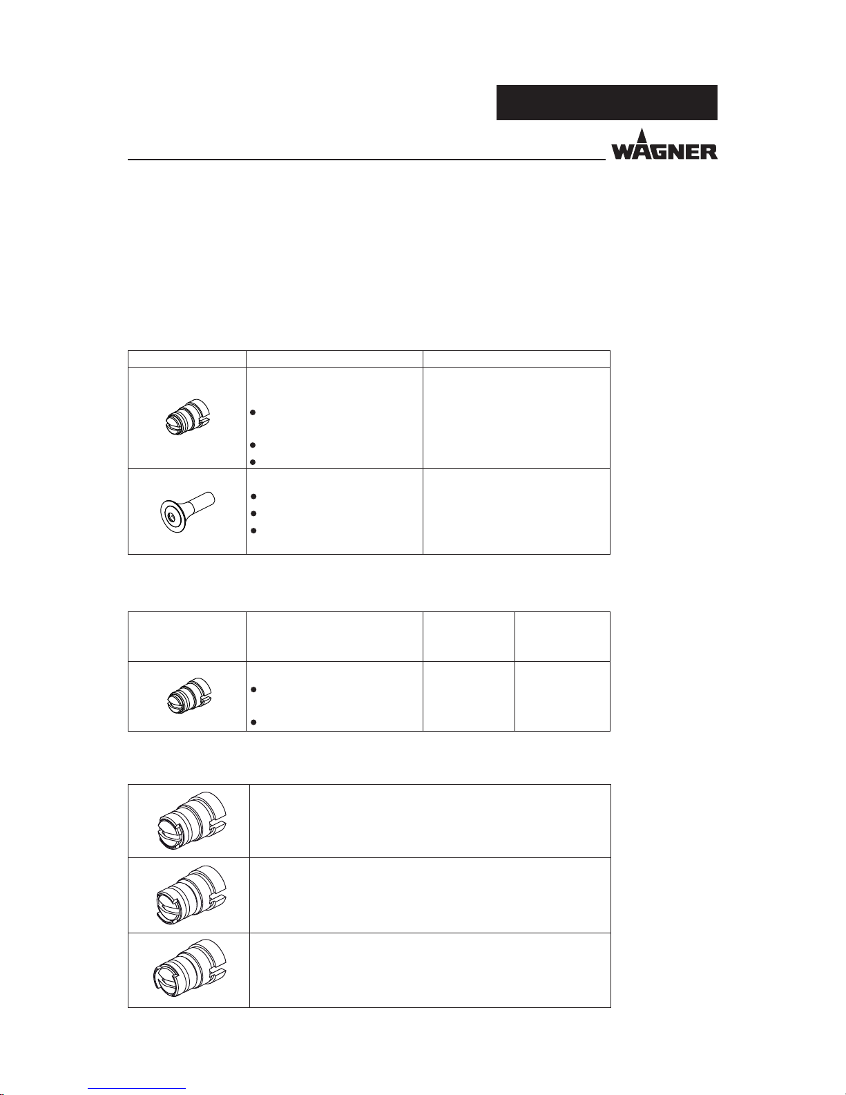
12 ACCESSORIES
12.1 FAN SPRAY NOZZLE
Order No. Designation
Fan spray nozzle, X1, complete
12.2 DEFLECTOR CONE
Order No. Designation
De ector cone, D18, complete
De ector cone, D25, complete
De ector cone, D34, complete
12.3 ELECTRODE HOLDER
Order No. Designation
Electrode holder, X1 F ET
Electrode holder, X1 R ET
Page 55

55
PEM-X1
P_01693
P_01694
P_01695
1
P_01696
OPERATING MANUAL
VERSION 03/2014 ORDER NUMBER DOC 2326020
12.4 HOSE TAKEUP
Order No. Designation
Hose take-up, D10-D12, complete
Hose take-up, D8-D10, complete
12.5 CORONASTAR RETROFIT SET
Pos Order No. Designation
CoronaStar, PEM-X1, complete
CoronaStar electrode, PEM-X1 ET
12.6 WEDGE TOOL
Pos K Stk Order No. Designation
Wedge tool, X1 + 20 wedges
available as accessory, not included in the purchased parts package
20x
Page 56

56
PEM-X1
P_01697
P_02163
OPERATING MANUAL
VERSION 03/2014 ORDER NUMBER DOC 2326020
12.7 NOZZLE EXTENSION, X1 VL 150/300/500
Pos K Stk Order No. Designation
Nozzle extension, X1 VL 150 (150 mm; 5.91 inches)
Nozzle extension, X1 VL 300 (300 mm; 11.81 inches)
1 2323338 Nozzle extension, X1 VL 500 (500 mm; 19.68 inches)
1 2324147 Fan spray nozzle, X1 VL ET
Round spray nozzle, X1 VL ET
available as accessory, not included in the purchased parts package
12.8 NOZZLE EXTENSION, X1 VL 750
Pos K Stk Order No. Designation
2330497 Nozzle extension, X1 VL 750 (750 mm; 29.53 inches)
1 2324147 Fan spray nozzle, X1 VL ET
2324148 Round spray nozzle, X1 VL ET
available as accessory, not included in the purchased parts package
Page 57

57
PEM-X1
P_01861
OPERATING MANUAL
VERSION 03/2014 ORDER NUMBER DOC 2326020
12.9 POWDER HOSE
Order No. Designation
Powder hose 9 mm
Powder hose 10 mm
Powder hose 11 mm
Powder hose 12 mm
12.10 GUN CONNECTION CABLE
Order No. Designation
2334275 Manual gun cable, PEM-X1 6m ET
2334568 Manual gun cable, PEM-X1 15m ET
Note:
The replacement of the gun cable may only be performed by Wagner service personnel!
12.11 WALL MOUNT
Order No. Designation
Wall mount with bracket
Page 58

58
PEM-X1
2x
2x
Tribo Corona
m /h
3.0
0.5
0.3
0.1
1.5
3
Tri
Ø
12
10
11
9
8
m /h
2.0
3
5.5
4.5
3.5
2.5
0 %
100 %
10
20
30
40
50
60
70
80
90
[μA] [Nm³/h] [%][kV]
[Nm³/h]
0.1
> 0.2
@
90 80 4.0 70
50 20 3.6 57
70 40 3.6 50
P5
P6
P7
P8
P9
P10
name 80 100 4.5 80
______________________________
www
✆
www.wagner-group.com/industry
______________________________
2x
82 20 3.6 45
P_01829
OPERATING MANUAL
VERSION 03/2014 ORDER NUMBER DOC 2326020
12.12 RECIPE STICKER
Order No. Designation
2331223 Recipe sticker
Page 59

59
PEM-X1
P_01716
OPERATING MANUAL
VERSION 03/2014 ORDER NUMBER DOC 2326020
12.13 POWDER MEASURING ADAPTER
Order No. Designation
Powder measuring adapter with X1 bag, complete
for measuring powder quantities for the PEM-X1 spray gun
The powder measuring adapter is slid onto the nozzle.
Risk of explosion due to electrostatic charging!
Danger to life and damage to the device.
Only use powder measuring adapter when high-voltage is
switched o !
DANGER
Page 60

60
PEM-X1
OPERATING MANUAL
VERSION 03/2014 ORDER NUMBER DOC 2326020
13 SPARE PARTS
13.1 HOW CAN SPARE PARTS BE ORDERED?
To ensure proper spare parts delivery, the following information is necessary:
Order number, designation, and quantity
The quantity need not be the same as the number given in the quantity column "Stk" on
the lists. This number merely indicates how many of the respective parts are used in each
component.
The following information is also required to ensure smooth processing of your order:
Identi cation in spare parts lists
Explanation of column "K" (labeling) in the following spare parts lists.
- Billing address
- Delivery address
- Name of the person to be contacted in the event of any queries
- Type of delivery (normal mail, express delivery, air freight, courier etc.)
= Wearing parts
Note: These parts are not covered by warranty terms
= Not part of the standard equipment but available as a special accessory.
Incorrect maintenance/repair!
Risk of injury and damage to the device.
Have repairs and part replacements carried out only by specially
trained sta or a WAGNER service center.
Before all work on the device and in the event of work
interruptions:
- Switch o the energy/compressed air supply.
- Ensure that all system components are grounded.
- Secure the device against being switched back on without
authorization.
Observe the operating manual and service manuals at all times
when carrying out work.
WARNING
Page 61

61
PEM-X1
1
3
4
5
6
7
10
P_01699
2
8
9
OPERATING MANUAL
VERSION 03/2014 ORDER NUMBER DOC 2326020
13.2 PEMX1 CORONA MANUAL GUN WITH A FAN SPRAY NOZZLE
PEM-X1 manual gun
Pos K Stk Order No. Designation
PEM-X1 Corona manual gun
Hose take-up, D10-12, complete
O-ring
Union nut, X1
Fan spray nozzle, X1, complete
Electrode holder, X1 F ET
Replacement protective wedge, X1
Gun hook, X1 ET
Screw
Wedge tool, X1
11 1 2313993 Hose, transparent 6 mm
Wearing parts
Not part of the standard equipment but available as a special accessory
Only available as a set
Page 62

62
PEM-X1
1
3
4
6
9
P_01661
2
7
8
5
OPERATING MANUAL
VERSION 03/2014 ORDER NUMBER DOC 2326020
13.3 PEMX1 CORONA MANUAL GUN WITH A ROUND SPRAY NOZZLE
PEM-X1 manual gun
Pos K Stk Order No. Designation
2335844 PEM-X1 Corona manual gun
2322761 Hose take-up, D10-12, complete
9971364 O-ring
2320464 Union nut, X1
Electrode holder, X1 R, with nozzle
6 1 Replacement protective wedge, X1
7
Gun hook, X1 ET
82 Screw
91 Wedge tool, X1
10 1 2313993 Hose, transparent 6 mm
Wearing parts
Not part of the standard equipment but available as a special accessory
Only available as a set
Page 63

63
PEM-X1
4
3
5
6
7
P_01700
2
1
OPERATING MANUAL
VERSION 03/2014 ORDER NUMBER DOC 2326020
Electrode holder, X1 R, with nozzles
Pos K Stk Order No. Designation
Electrode holder, X1 R, with nozzle
Electrode holder, X1 R ET
Replacement protective wedge, X1
De ector cone sleeve, X1
De ector cone, D18, complete
De ector cone, D25, complete
De ector cone, D34, complete
Wearing parts
Not part of the standard equipment but available as a special accessory
Only available as a set
13.4 ELECTRODE HOLDER, X1 R
Page 64

64
PEM-X1
OPERATING MANUAL
VERSION 03/2014 ORDER NUMBER DOC 2326020
14 DECLARATION OF WARRANTY AND CONFORMITY
14.1 IMPORTANT NOTES REGARDING PRODUCT LIABILITY
14.2 WARRANTY CLAIM
As a result of an EC regulation e ective from January 1, 1990, the manufacturer shall only
be liable for his product if all parts originate from him or are approved by him, and if the
devices are properly mounted, operated and maintained.
The manufacturer will not be held liable or will only be held partially liable if third-party
accessories or spare parts have been used.
With genuine WAGNER accessories and spare parts, you have the guarantee that all safety
regulations are complied with.
Full warranty is provided for this device:
We will at our discretion repair or replace free of charge all parts which within 24 months
in single-shift, 12 months in 2-shift or 6 months in 3-shift operation from date of receipt by
the purchaser are found to be wholly or substantially unusable due to causes prior to the
sale, in particular faulty design, defective materials or poor workmanship.
The type of warranty provided is such that the device or individual components of the
device are either replaced or repaired as we see t. The resulting costs, in particular
shipping charges, road tolls, labor and material costs will be borne by us except where
these costs are increased due to the subsequent shipment of the device to a location other
than the address of the purchaser.
We do not provide warranty for damage that has been caused or contributed to for the
following reasons:
Unsuitable or improper use, faulty assembly or commissioning by the purchaser or a
third party, normal wear, negligent handling, defective maintenance, unsuitable coating
products, substitute products and the in uence of chemical, electrochemical or electrical
agents, except when the damage is attributable to us.
Components that have not been manufactured by WAGNER are subject to the original
warranty of the manufacturer.
Replacement of a component does not extend the period of warranty of the device.
The device should be inspected immediately upon receipt. To avoid losing the warranty,
we or the supplier company are to be informed in writing about obvious faults within 14
days upon receipt of the device.
We reserve the right to have the warranty compliance met by a contracting company.
The services provided by this warranty are dependent on evidence being provided in the
form of an invoice or delivery note. If the examination discovers that no warranty claim
exists, the costs of repairs are charged to the purchaser.
It is clearly stipulated that this warranty claim does not represent any constraint on statutory
regulations or regulations agreed to contractually in our general terms and conditions.
J. Wagner AG
Page 65

65
PEM-X1
OPERATING MANUAL
VERSION 03/2014 ORDER NUMBER DOC 2326020
14.3 DECLARATION OF CONFORMITY
PEM-X1 manual gun 2326024
Herewith we declare that the supplied version of
- PEM-X1 manual gun, order no. 2322587, 2335844
complies with the following provisions applying to it:
- 94/9/EC (ATEX Directive)
- 2006/42/EC (Machine Directive)
- 2004/108/EC (EMV Directive)
- 2002/95/EC (RoHs Directive)
- 2002/96/EC (WEEE Directive)
Applied standards, in particular:
Applied national technical standards and speci cations, in particular:
- BGI 764
Identi cation:
0102 II 2D 2mJ
PTB 12 ATEX 5002
EN 50050-2: 2012
CE Certi cate of Conformity
The CE certi cate of conformity is enclosed with this product. If needed, further copies
can be ordered through your WAGNER dealer by specifying the product name and serial
number.
Order number:
Page 66

66
PEM-X1
OPERATING MANUAL
VERSION 03/2014 ORDER NUMBER DOC 2326020
14.4 EC TYPE EXAMINATION CERTIFICATE
Page 67

67
PEM-X1
Specialconditionsofuse:
ThesourceelectricalconnectionfortheControlUnitsaretobeconnectedinanunclassified
(ordinary)locationonly.
P_00309
OPERATING MANUAL
VERSION 03/2014 ORDER NUMBER DOC 2326020
14.5 FM APPROVAL
The PEM-X1 powder spray gun is approved in the USA and Canada using con guration
drawing no. 2309729.
Page 68

68
PEM-X1
OPERATING MANUAL
VERSION 03/2014 ORDER NUMBER DOC 2326020
Page 69

69
PEM-X1
OPERATING MANUAL
VERSION 03/2014 ORDER NUMBER DOC 2326020
Page 70

70
PEM-X1
OPERATING MANUAL
VERSION 03/2014 ORDER NUMBER DOC 2326020
Page 71

Page 72

C
E
R
T
I
F
I
E
D
Order No. 2326020
Edition 03/2014
Germany
Phone
Fax
E-mail
Switzerland
Phone
Fax
More contact addresses on the internet at:
Company/Locations/WAGNER worldwide
Subject to changes without notice
Document No. 11130849
Version B
 Loading...