

Page 1
http://www.wagner-group.com
Operating Manual
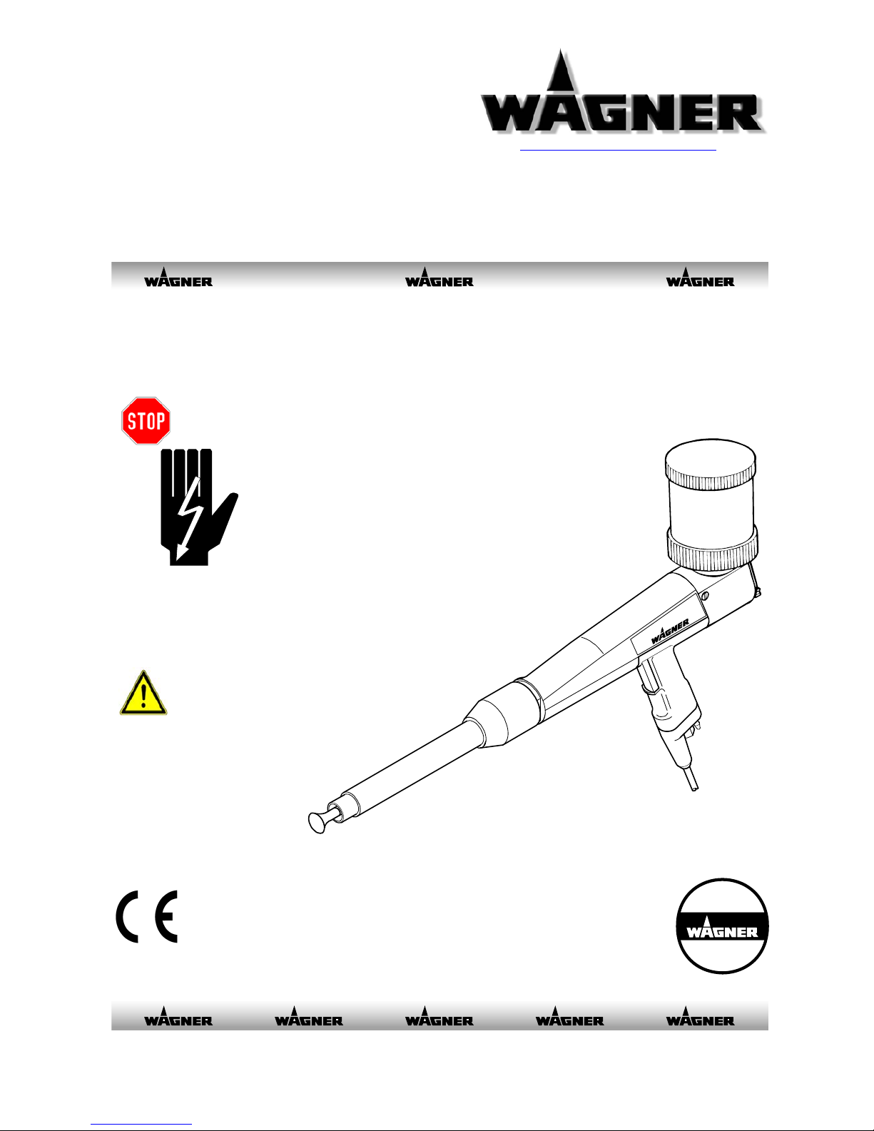
Tribo Cup Gun
DANGER
High Voltage!
Turn power off
before servicing!
Read rules for safe
operation and
instructions
carefully!
CAUTION
pemtg3_0000
0351967
PEM-TG3
C
E
R
T
I
F
I
E
D
D
I
N
I
S
O
9
0
0
1
04/2006 0351717
Page 2
Introduction
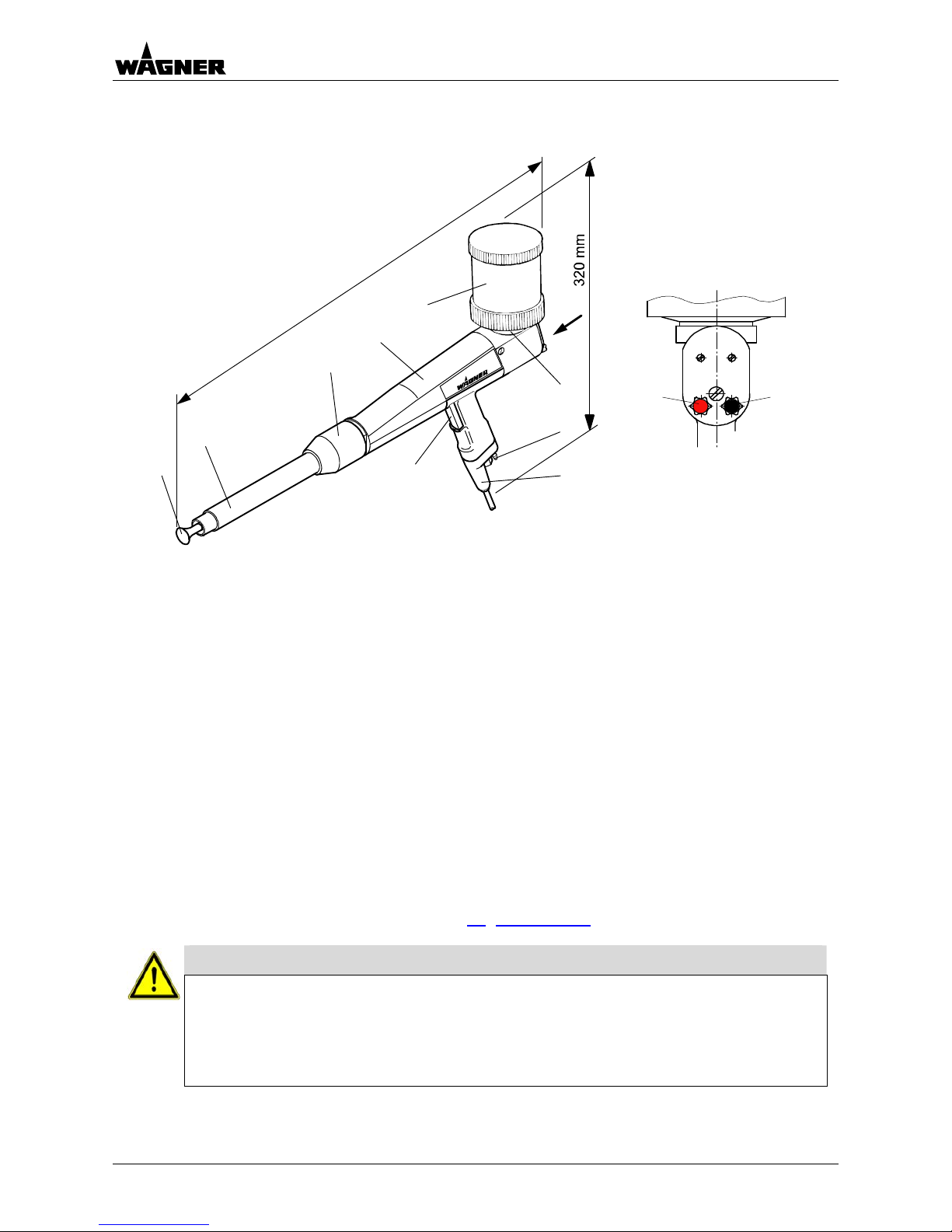
Tribo Cup Gun PEM-TG3 Article No. 0351036
00_Pemtg3_Aufbau.doc
570
m
m
X
A
B
F
G
J
E
C
D
H
Pemtg3_0001a
X
K L
Pemtg3_0001b
A Deflector cone
B Nozzle body
C Outer nut
D Spray gun body
E Trigger
F Air supply (input air)
G Electrical connection
H Powder container with fluidization
J Adapter with integrated powder injector
K Setting knob red for setting the feed air
L Setting knob black for setting the Tribo air
The Tribo cup gun PEM-TG3 is used for processing all coating powders suitable for friction
charging.
The Tribo cup gun is mainly suitable for laboratory tests, sample coating and/or low volume
production.
By actuating the trigger the compressed air supplies to the gun is turned on. This compressed
air is required for Tribo, feed, dosing and fluid air applications.
This cup gun can be operated with the control unit EPG 2008.
The cup gun is equipped with a powder container with a capacity of 500 cm
3
. You can also
mounted different powder containers on the cup gun.
You will find the article numbers in chapter 10
"Accessories".
Caution
The operator must ensure that the spray gun PEM-TG3 s only connected to Wagner
devices!
High room temperatures and, in particular, laying hoses in areas exposed to sunlight in
factory buildings must be avoided!
To secure the spray guns, the control unit must be switched off!
2 0351717 - PEM-TG3 04/2006
Page 3

Introduction
Table of contents Page
1. Safety regulations.......................................................................................................5
1.1 Safety hints....................................................................................................................5
1.2 EU Declaration of conformity.........................................................................................8
2. Preparing the spray gun.............................................................................................9
2.1 Selection of the suitable equipment ..............................................................................9
2.2 Mounting the powder container...................................................................................10
2.3 Connecting the spray gun ...........................................................................................10
2.4 Grounding....................................................................................................................11
3. Working with the spray guns...................................................................................12
3.1 Starting up the spray gun and adjusting Tribo air........................................................12
3.2 Switching off the spray gun.........................................................................................12
3.3 Performing a color change..........................................................................................13
4. Maintenance and cleaning........................................................................................15
4.1 Replacing the spray gun..............................................................................................15
4.2 Cleaning the spray gun and replacing the wear parts.................................................17
4.3 Check the standard settings........................................................................................18
4.4 Disposal.......................................................................................................................19
5. Rectification of malfunctions...................................................................................20
6. Technical data ...........................................................................................................21
7. Applicable safety regulations ..................................................................................22
8. Warranty.....................................................................................................................23
9. Scope of delivery and spare parts lists...................................................................24
9.1 How to order spare parts.............................................................................................24
9.2 Scope of delivery and spare parts list PEM-TG3 ........................................................25
10. Accessories...............................................................................................................27
10.1 Powder container ........................................................................................................27
10.2 Special accessory .......................................................................................................28
04/2006 0351717 - PEM-TG3 3
Page 4
Introduction
00_..doc
This manual contains information and hints for the service, repair and maintenance of the
equipment. The user must obey all the rules of operation found in this manual; failure to do so
will render the warranty invalid.
Wagner powder systems are designed to meet the most stringent safety requirements. They
can be operated in compliance with generally applicable safety codes and applicable national
safety regulations.
Please pay particular attention to the parts marked by the following symbols. Follow the
instructions exactly, in the interests of both your own safety and the correct functioning of the
unit.
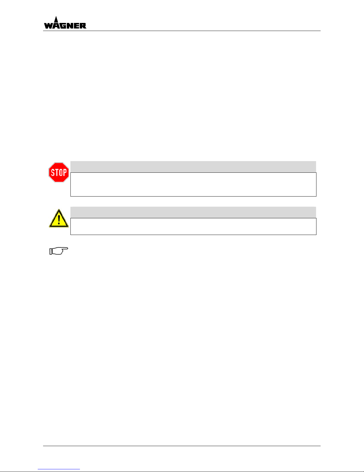
Warning
This symbol draws attention to the fact that if the operating instructions, working
instructions, prescribed working sequences etc. are not followed exactly, this can
lead to injury or even fatal accidents.
Caution
This symbol indicates that failure to follow the operating instructions, working
instructions, prescribed working sequences etc. exactly can lead to material damage.
Hint
This symbol draws your attention to useful additional information and tips. Failure to
observe these instructions can cause malfunctions.
4 0351717 - PEM-TG3 04/2006
Page 5
Safety regulations
1. Safety regulations
1.1 Safety hints
010101_ .doc
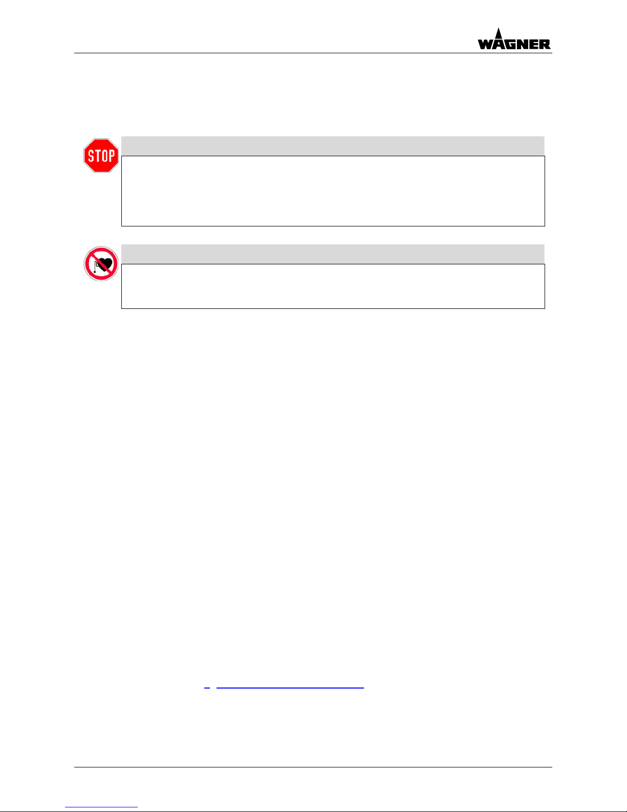
Warning
This equipment can be dangerous if it is not operated in accordance with this
operating manual!
There might be additional regulations to be observed, put into effect by
governmental, state or other official agencies or local security (fire)
departments
!
Warning
Under no circumstance may persons with a cardiac pacemaker come close
to the area between the tip of the spray gun and the work piece to be
coated!
The following rules must be observed in order to ensure a safe and efficient use of the
equipment:
• The user has to observe particularly the safety
guidelines of the VdS, the local professional and
security institutions.
• Trained and qualified personnel may only operate the electrostatic coating equipment.
• The spray gun may only be operated in powder
coating booths or on powder coating stands that
are equipped with a ventilation system.
• The user has to make sure, that the average
powder/air concentration does not exceed 50%
of the LEL (maximum allowed concentration of
powder in air). If a reliable LEL value is not
available, the average powder/air concentration
may not exceed 10 g/m³.
• Over sprayed powder must be reliably collected.
• Adhere to the instructions given by the manufac-
turers and to the prevalent local laws on the
environment when disposing of waste coating
powder.
• The main power connection for operation of the
Wagner powder equipment must be electrically
interlocked with the exhaust system of the
powder coating booth.
• In the event of faults or defects, repair work is to
be performed at the user's discretion.
• The user must conduct periodic checks of the
powder spray equipment (at least every year)
with regard to explosion-protection.
• Repairs may only be carried out by trained technicians and may never be carried out in an
explosion hazardous area. Protective measures
against explosions must still be installed.
• The work area must have an electrostatically
conductive floor (measured in accordance with
EN 1081).
• All conductive parts in the work area must be
electrostatically grounded (work area = 1 m
around every spray location or opening in the
booth).
• All persons inside the work area must wear
electrostatically conductive footwear.
• Spray guns should be operated with bare hands!
If gloves are used they must be made of conductive material.
• Guideline 94/9/EG: The device is suited for the
applications it was designed for, even in
explosion-hazard areas.
Also refer to chapter 7
"Applicable safety regulations".
04/2006 0351717 - PEM-TG3 5
Page 6

Safety regulations
010102_ .doc
• Wear suitable work clothing
• Use breathing protection or a vizard for work
which produces powder and when
developing solvent steams:
Avoid health dangers by inhalation and skin
contacts of solvent steams and lacquer aerosols; Cornea injuries by splashes in the eye.
• Check the equipment for damage
Before operating the system, check if slightly
damaged parts still function correctly. Check
whether the moving parts operate properly,
whether they jam and whether parts are
damaged.
Damaged parts should be repaired or
replaced by a Wagner customer service.
Warning
For your own safety, use only accessories and equipment listed in the
operating manual. The use of individual parts other than those
recommended in the operating manual may create a hazard to personal safety.
Use only original Wagner replacement parts!
Alteration or repair of Wagner original spare parts may cause fatal
accidents or explosions in the coating system!
6 0351717 - PEM-TG3 04/2006
Page 7

Safety regulations
HAZARD PREVENTION
Electrostatic arcing may cause an explosion or fire.
Mixtures of powder and air can explode or ignite
causing property damage and/or severe injury.
• Operator must be grounded. Grounding straps must be used
when wearing rubber soled shoes.
• Operator must remove all metallic objects from his or her
person, which are not grounded.
• The object being sprayed must be grounded.
• All metallic objects within the spray area must be grounded
(including spray booth, part hangers, fire extinguishers, etc.)
• Grounded conductive floor must be provided in spray area.
• Turn off the Power Pack and unplug from outlet before flushing
out the gun, cleaning or replacing parts on the gun such as
changing tips.
Explosion or fire. Mixtures of powder and air can
explode or ignite causing property damage and/or
severe injury.
• Exhaust and fresh air introduction must be provided to keep the
air within the spray area free of accumulation of flammable
atmosphere.
• Smoking must not be allowed in spray area.
• Fire extinguishing equipment must be present and in working
order.
• Electrostatic arcing must be prevented.
(See Electrostatic arcing)
• When cleaning the system, use only materials recommended
by the coatings manufacturer. Be sure Power Pack is turned off
and unplugged.
• Avoid all ignition sources such as static electricity sparks, open
flames such as pilot lights, hot objects such as cigarettes and
sparks from connecting and disconnecting power cords and
working light switches.
• To prevent hazardous concentrations of flammable
atmospheres, spray only in a properly ventilated spray booth.
• Never operate spray gun unless ventilation fans are operating
properly.
• Check and follow all National, State and Local codes regarding
air exhaust velocity requirements.
• Ventilation must be maintained during the cleaning operation.
Toxic Substances: Some materials may be harmful if
swallowed or come in contact with the skin.
• Follow the requirements of the Material Safety Data Sheet
supplied by the coatings manufacturer.
• Exhaust and fresh air introduction must be provided within the
spray area to keep the air free of high powder accumulations.
• Wear a mask or respirator. Read all instructions for the mask to
insure that it will provide the necessary protection against the
inhalation of powder.
General
• Read all instructions and safety precautions before operating.
• Comply with all appropriate local, state and national codes
governing ventilation, fire prevention, and operation of
Electrostatic equipment usage.
• The United States Government Safety Standards have been
adopted under the Occupational Safety and Health Act. These
standards, particularly the General Standards, Part 1910 and
the Construction Standard, Part 1926, should be consulted.
• NFPA Standard No. 33 is to be followed when setting up your
spray area. Contact the National Fire Protection Association,
Batterymarch Park, Quincy, Massachusetts, 02269 for more
information.
• Check with insurance company for additional requirements.
• Use only identical replacement parts.
• Personnel must be given training in accordance with the
requirements of NFPA Standard No. 33 chapter 18.
• It is the duty of all personnel responsible for the spray
equipment operation and maintenance to read and understand
all safety information furnished with this equipment.
04/2006 0351717 - PEM-TG3 7
Page 8

Safety regulations
1.2 EU Declaration of conformity
0103_ .doc
Wagner hereby declares that the unit described in these operating instructions has been
designed and manufactured according to the provisions of EU Directives 98/37/EC,
94/9/EC, 73/23 EEC and 89/336 EEC.
The following European standards were applied:
EN 12100-1/-2 EN 50281-1-1/-1-2 EN 61000-6-1
EN 61000-6-2 EN 61000-6-3 EN 60204-1
EN 50053-2 EN 50050 EN 50177
The following German standards and/or Guidelines were applied:
BGI 764
The product includes an EU declaration of conformity. This can be ordered again if
necessary from your WAGNER dealer by giving details of the product and serial number
involved.
The EU declaration of conformity has the number 0351967.
8 0351717 - PEM-TG3 04/2006
Page 9
Preparing the spray gun
04/2006 0351717 - PEM-TG3 9
2. Preparing the spray gun
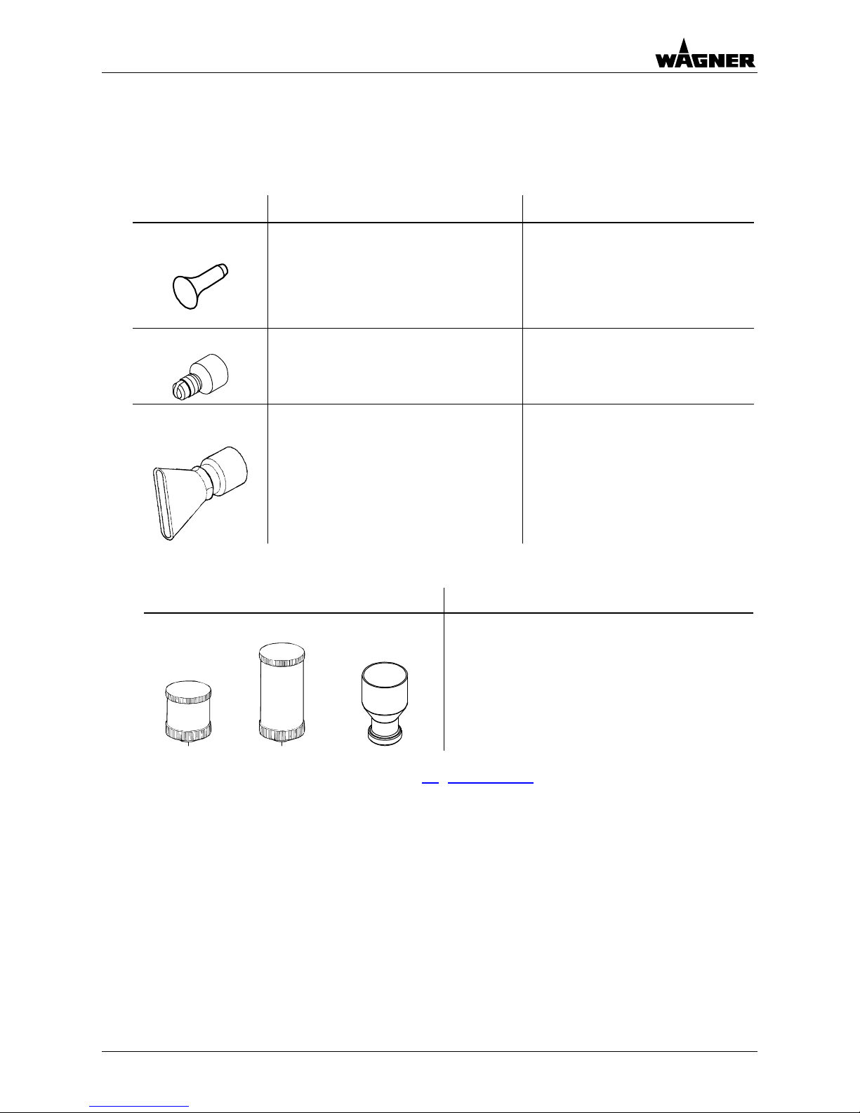
2.1 Selection of the suitable equipment
0201_Duesenauswahl_tribo.doc
Nozzle Overview Application Spray pattern
Deflector cone
• Wire goods
• Grid designs
Oval powder cloud:
Size is dependent on the deflector
cone diameter.
For powder quantities from:
50 ... 300 g/min
Fan spray nozzle
Difficult workpieces:
•
Undercuts
• Profiles
Widely spread flat powder cloud.
For powder quantities:
from 50 ... 150 g/min
Wide fan spray
nozzle
Difficult workpieces:
• Undercuts
• Profiles
Widely spread flat powder cloud.
For powder quantities:
from 100 ... 250 g/min
Powder container Comments
500 cm3 900 cm3 220 cm
3
Select the powder container size dependently
of the powder volume required for coating.
You will find the article numbers in chapter 10
"Accessories".
Page 10
Preparing the spray gun
10 0351717 - PEM-TG3 04/2006
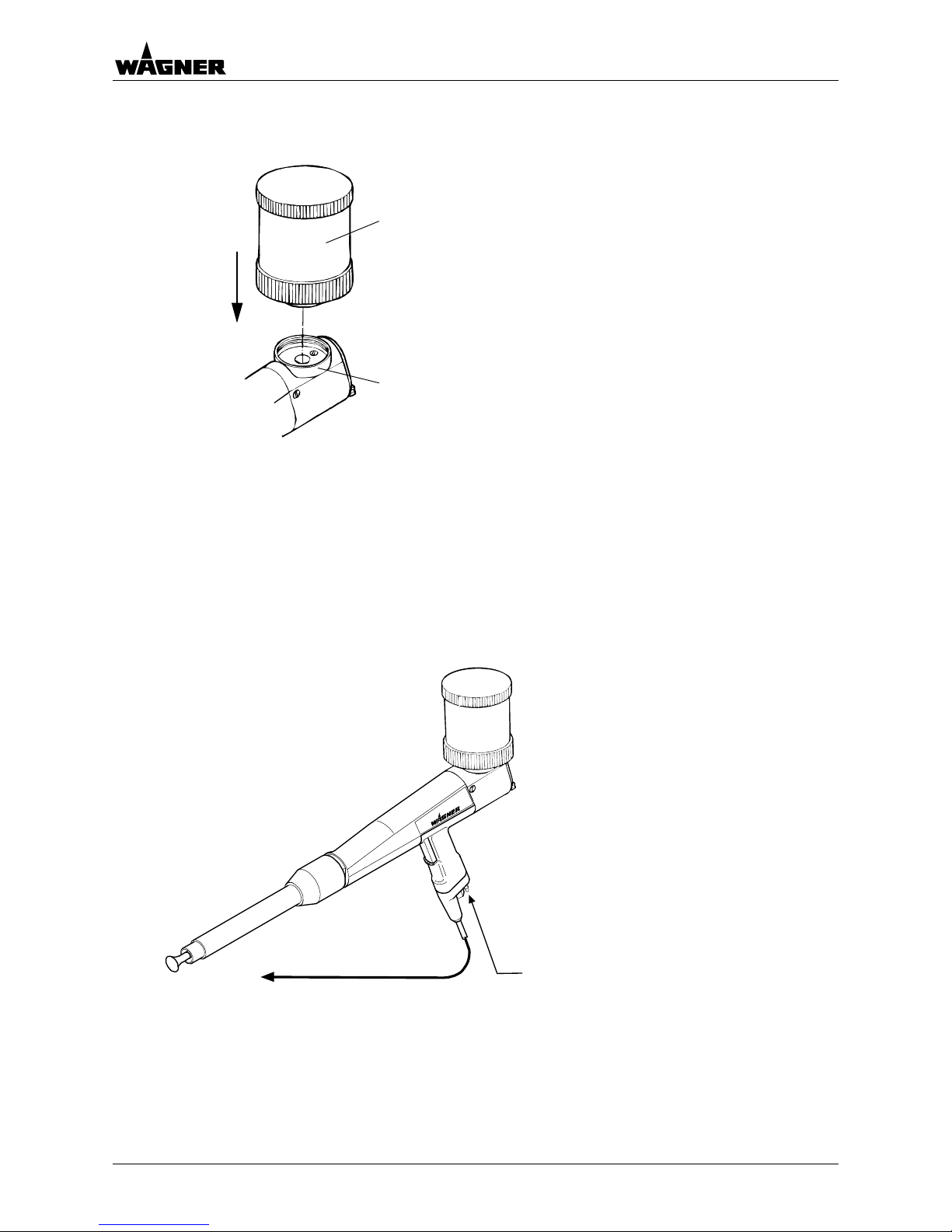
2.2 M ounting the powder container
H
J
pemcg4_0002a
The cup gun is delivered in two dismantled parts:
• spray gun and
• powder container (500 cm
3
)
Screw the powder container H onto the adapter J,
turning the powder container simultaneously right up to
the limit, thus ensuring that it is securely closed.
2.3 Connecting the spray gun
Pemtg3_0003
• Connect the spray gun to the
control unit
A with the electrical
cable.
• Connect the black hose (external
∅ 6x2) for the air supply to the spray
gun.
Air supply
B from the control unit
to the electrical connection
A at the control unit
Page 11

Preparing the spray gun
04/2006 0351717 - PEM-TG3 11
Rückwand EPG 2008
the spray gun is connected to
the EPG 2008, then the reduction
piece (6/8) must be placed at the
other end of the hose and connected
to the Y-plug connection
B.
• The Y-plug connection (8-8) is
connected with the two blue hoses
(external ∅ 8x1.5)
C to the feed and
dosage air connection of the
EPG 2008.
• The air vent has to be blocked with
the stopper
D.
The required parts are listed in section
"Special accessory
• When
".
2.4 Grounding
For safety reasons, the spray gun must be properly grounded. This occurs through the
electrical cable.
0203_ .doc
Good grounding of the workpiece is also necessary for optimum powder coating.
A poorly grounded workpiece causes:
• dangerous electric charging of the workpiece
• back-spray onto spray gun and user
• uneven coating
• very bad wrap around
Warning
Sparks between workpiece and conveyor hooks (hangers) can occur if hooks or
other hanger parts are not completely cleaned!
These sparks can cause heavy radio frequency interference.
Page 12

Working with the spray gun
12 0351717 - PEM-TG3 04/2006
3. Working with the spray guns
3.1 tarting up the spray gun and adjusting Tribo air
S
Caution
The powder cup may only be filled up to 75%, as fluidization swells the volume of the
powder.
K L
Pemtg3_0001b
• Open the powder cup and fill it up to max. 75% of the volume
with pow
• Switch o
quantity
• Shut off the feed air with the red setting knob K.
• Actuate the trigger and keep it actuated.
• Check whether sufficient fluid air is present. Correct the fluid air
if required as
described in chapter 4.3
der, but do not close the cup yet.
n the control unit and with knob 22 adjust the overall air
to approximately 3 Nm
3
/h.
.
• Close the powder cup.
• Set the feed air for the desired powder output quantity wit h the
red setting knob K.
• Correct the Tribo air with the black setting knob L if required.
Hint
• The amount of fluid air depends on the characteristics of the powder.
• Avoid a build up of powder dust (too much fluid air) in the powder cup!
3.2 Switching off the spray gun
Hint
At every work interruption, blow through the spray gun and the powder feed
components and remove any residual powder. These measures help in preventing the
build-up of powder deposits and powder su ed on
rges when the spray gun it turn
again.
Page 13

Working with the spray gun
04/2006 0351717 - PEM-TG3 13
X
H
J
pemcg4_0002b
X
K L
Pemtg3_0001b
• Release the spray gun trigger.
• The powder feed is deactivated.
• Remove the powder cup H from the
adapter J.
• With the black setting knob L open
the Tribo air all the way and with
the red setting knob K open the
ir quantity to the
maximum with knob 22.
• Hold the spray gun in the coating
booth, actuate the spray gun
trigger and remove any residual
powder inside the spray gun.
• Now the control unit can be
switched off.
. erforming a color change
Duri hange all parts carrying powder must be thoroughly cleaned of powder
resid lowing only the procedure for the powder spray gun is described.
feed air all the way.
• Set the overall a
3 3 P
ng a color c
ue. In the fol
Hint
Use a separate cup for each color if you want to shorten the cleaning time of the powder
cup.
• Release the spray gun trigger.
• The powder feed is deactivated.
Page 14

Working with the spray gun
14 0351717 - PEM-TG3 04/2006
J
5
6
3
H
2
4
1
Pemtg3_0005a
K L
Pemtg3_0001b
• Unsc
adap
rew the powder cup H from the
ter J.
• With the black setting knob L open the
Tribo air all the way and with the red
• Set the overall air quantity to the
maximum with knob 22.
• Hold the spray gun in the coating
booth, actuate the spray gun trigger
and remove any residual powder
inside the spray gun.
• Switch the control unit off and secure
it against being unintentionally
switched on again.
ousing 5.
body 3 off the
setting knob K open the feed air all the
way.
• Pull the deflector cone 1 off the
charging body 4.
• Unscrew the outer nut 2 from the
spray gun h
• Carefully pull the nozzle
powder tube 6.
• Carefully pull the charging body 4 out
of the powder tube 6.
Caution
When pulling , ensure that the charging body is not
damaged!
out and inserting the parts
• Remove powder residue from the parts removed, from the spray gun and the powder
container.
• Mount the cleaned or a new powder container.
• Carefully push the charging body 4 into the powder tube 6.
• Push the nozzle body 3 over the powder tube 6 and tighten using the outer nut 2.
• Slide the deflector cone 1 back over the charging body 4.
Activate the spray guns in accordance with chapter:
" g up the spray gun and adjusting Tribo air
•
Startin
".
Page 15

Maintenance and cleaning
04/2006 0351717 - PEM-TG3 15
4. Maintenance and cleaning
WARNING
CAUTION
WH
THE
FAI
RES N EXPLOSION/FIRE.
Turn power pack to the "OFF" position and unplug from
power source before starting to clean.
• Exhaust and fresh air introduction must be maintained
during the clean up operation.
• Keep cleaning materials in approved safety containers.
• All personnel and cleaning equipment, including
container used in cleaning operation, must be
grounded.
• DO NOT turn on the POWER PACK until the cleaning
operation has been completed, all cleaning materials
have been removed from spray area, and spray area is
free of any mixtures of powder and air produced by the
cleaning operation.
• If defects in the equipment are found, DO NOT use until
repairs are completed.
• Be sure the Power Pack is turned off and unplugged
from the power source.
NOTE
• The powder passages of the spray gun should be
cleaned while cleaning the powder hose and
powder pump, following instructions, provided with
the powder pump (injector).
(See powder injector operating manual)
• Clean the spray tip by removing from spray gun,
flushing with air and replacing on spray gun.
EN CLEANING THE ELECTROSTATIC SYSTEM,
SE SAFETY PROCEDURES MUST BE FOLLOWED.
LURE TO FOLLOW THESE PROCEDURES MAY
ULT IN A
• Clean equipment immediately after use.
• NEVER IMMERSE SPRAY GUN OR PARTS OF IT IN
ANY FLUID AT ANY TIME.
•
4.1 Replacing the spray gun
0401_ .doc
Before you commence the replacement of the spray gun any powder residue must be
removed thoroughly.
Caution
Repair or replacement of the spray gun or parts of the spray gun are only allowed to be
performed outside the hazard area and in a suitable place by specialist personnel!
The wearing parts in the spray gun, marked in the spare parts list with *, must be regularly
checked and, if necessary replaced.
Page 16

Maintenance and cleaning
16 0351717 - PEM-TG3 04/2006
0401_Pemtg3_Ausbauen.doc
H
J
D
G
M
F
Pemtg3_0004
• Switch the control unit and/or the powder
feed off.
• Unscrew the powder container H from
the adapter J.
• Remove the air supply (input air) F from
the spray gun D.
• Remove the electrical cable H from the
control unit K.
Page 17

Maintenance and cleaning
04/2006 0351717 - PEM-TG3 17
4.2 ing the wear parts
Cleaning the spray gun and replac
Caution
Never place the spray gun or parts of the spray gun in cleaning agent!
When pulling out and inserting the wear parts, ensure that the charging body is not
damaged!
5
6
4
3
2
1
Pemtg3_0005b
• Pull the deflector cone 1 off the
charging body 4.
• Unscrew the outer nut 2 from the spray
gun housing 5.
• Carefully pull the nozzle body 3 off the
powder tube 6.
• Carefully pull the charging body 4 out
of the powder tube 6.
• Check the removed parts for wear.
The entire charging body can be
replaced with a new one.
It is also possible to dismantle the charging body and merely replace the parts affected by
wear.
12
13
7
8
9
11
10
Pemtg3_0006
• Carefully Unscrew the tip 8 from the
threaded rod 7 and dismantle the
charging body.
• Unscrew the air nozzle 12 from the
deflector cone rod 13 if worn and
replace it with a new one.
• Complete clean residual powder from
all parts.
• Replace worn parts with new ones.
• Reassemble the charging body.
• Carefully push the charging body into
the gun and reassemble the gun.
Page 18

Maintenance and cleaning
18 0351717 - PEM-TG3 04/2006
4.3 heck the standard settings
The spray gun has been set at the factory to provide the optimum spray cloud with standard
powders:
Input air pressure: max. 43.5 psi (3 bar)
Powder output quantity: max. 200 g/min
Type of powder: Standard powders with grain size distribution of
35 ... 40% < 32 μm
• Check the input air pressure and readjust it
• Check the fluid base of the powder container fo with a new one if
required.
C
if required.
r damage and replace
K L
N M
Pemtg3_0001c
K Feed air adjustment 1)
L Tr
M Dosage air
N Flu
1) Rotate coun
ibo air adjustment 1)
adjustment 1)
id air adjustment 1)
ter-clockwise to increase the values.
Caution
Never turn the spindles M and N all the way in (danger of damaging the parts!).
By adjusting the dosage air M and/or the Tribo
reset if required.
air L the powder cloud can be readjusted or
Hint
Normally, the dosage air M and the atomizing air N do not have to be adjusted.
Page 19

Maintenance and cleaning
04/2006 0351717 - PEM-TG3 19
4.4 Disp
04_Entsorgung.doc
osal
waste
waste electrical
plementation in accordance with
f together with household
environmentally friendly way!
Only for EU countries
Do not dispose of electric tools together with household
material!
In observance of the European Directive 2002/96/EC on
and electronic equipment and im
national law, this product is not to be disposed o
waste material but must be recycled in an
Wagner or one of our dealers will take back your used Wagner waste electrical or electronic
equipment and will dispose of it for you in an environmentally friendly way. Please ask your
local Wagner service center or dealer for details or contact us direct.
Page 20

Rectification of malfunctions
20 0351717 - PEM-TG3 04/2006
5. Rectification of malfunctions
Malfunction Cause Rectification
- Fault in the monitoring
- Electrical cable from s
to c
device
pray gun
- Contact Wagner Service
ontrol unit faulty
N
wder use
ear
ble powder
- Replace worn parts
o Tribo current
display on PEM-TG3
- Unfit po d - Use suita
- W
Poor wrap around
Back spray
- Inadequate or no ground - See chapter 2.4
Pulveraustritt un-
oder
ir su p
- Soiling in the powder
- Blockages in the gun
- Feed air / dosage air ratio
- Wear
supply
properly
- Empty the powder container
and blow through powder air
channels
- Dismantle spray gun and clean
the parts in accordance with
chapter 3.3
gleichmäßig
nicht ausreichend.
- Bad compressed a
- Powder container is
p ly - Check compressed air
not sitting - Tighten powder container
tightly
incorrect
- Redetermine the feed air- /
with chapter 4.3
dosage air ratio in accordance
- Replace worn parts
Spray pattern is
une
- Nozzle system wear
- Replace nozzle system in
ven accordance with chapter 4.2
Fluidizat
quate or has failed
ion inade-
tainer is not sitting
tightly
- Soiling or blockage of fluidized
bed
- Wear
- Readjust the fluid air with the
spindle N in accordance with
- Fluid air too low
- Powder con
chapter 4.3
- Retighten the powder container
- Clean fluidized bed connection
and fluidization disc
- Change worn out parts
(e.g. fluidization disc)
No powder output
- The powder container is empty
- The spray gun is clogged
- Refill with powder
- Blow through the spray gun
Page 21

Technische Daten
04/2006 0351717 - PEM-TG3 21
6. echnical data
Weight: 990 g
Electrical:
Design: as per EN 50177 and EN 50050
Protection class: IP 54
Pneumatic:
Input air pressure: max. 29 psi (2 bar - standard setting)
Powder output quantity:
Required compressed air quality:
T
max. 200 g/min at 43.5 psi (3 bar)
06_ .doc
Quality class
Compressed air quality according to ISO 8573.1
5
Max. residual water:
(pressure dew point in °F at 100 psi
/ °C at 700 kPa)
+44.6 °F / +7 °C
2
Max. oil contents: 0.1 mg oil/m3 / 0.1 oz/ft3
3
Max. concentration: 5 mg/m3 / 5 oz/ft3
3
Max. particle size:
5 μm / 5 microns
Ambient conditions:
low temperature powders are used, the ambient temperature may have to be lower than
6 °F (30 °C).
If
8
Volume measures:
For volumes, specified in Nm3 (standard cubic meters). One cubic meter of a gas at
32 °F (0 °C) and 1.013 bar is called norm cubic meter.
1 Nm
3
/h = 35.3 ft3/h; 1 bar = 14.504 psi
Page 22

Applicable safety regulations
22 0351717 - PEM-TG3 04/2006
7. Applicable safety regulations
07_ .doc
EN
N 5
-2
Electrical equipment for use in areas with flammable dust
(Beuth-Verlag,
Berlin)
EN 61000-6-1 Electro-magnetic compatibility (EMC)
Generic standard resistance to interference
(Beuth-Verlag,
Berlin)
EN 61000-6-2 Electro-magnetic compatibil
Basic Standards – Interference
EN 61000-6-3 Electro-magnetic compatibil
Generic standard interference emi
EN 60204-1 VDE guidelines for the elec
BGI 764 Safety regulations for electr
equipment's (Operating condition
BGR 132
(ZH1/200)
Safety regulations governing preve
electrical charging
EN 12981 Safety requirements for coating equi
organic powder
h-Verlag,
Berlin)
EN 50050 Electrostatic manual powder coating equipment
(Beuth-Verlag,
Berlin)
systems
Instructions for fire fighting in electric equipment and nearby
(Beuth-Verlag,
Berlin)
VdS 2093 and
VdS 2325
Safety regulations governing CO
VDE 0134 Instructions for first aid in case of accid
(Beuth-Verlag,
12100-1/-2 Machine Safety
(Beuth-Verlag,
Berlin)
0281-1-1/ E
-1
ity (EMC)
resistance within industry
(Beuth-Verlag,
Berlin)
ity (EMC)
ssions
(Beuth-Verlag,
Berlin)
trical equipment of machines
(Beuth-Verlag,
Berlin)
ostatic powder coating in coating
s)
(C. HeymannsVerlag, Cologne)
ntion of combustion during
(C. HeymannsVerlag, Cologne)
pment in spray booths for
(Beut
EN 50053-2 Regulations for selecting, installing and operating electrostatic
powder coating systems, electrostatic manual powder coating
(Beuth-Verlag,
Berlin)
VDE 0132
2
fire extinguishers
(VdS Box 10 20 24
50460 Cologne)
ent
Berlin)
Page 23

Warranty
04/2006 0351717 - PEM-TG3 23
8. Warranty
08_ .doc
What is arranty? covered by this w
Faulty o ced acco ral delivery conditions.
Within t rrant period, Wag tive
parts without charge if such parts are returned with transportation charges prepaid to the
earest authorized service center. If Wagner is unable to repair this product so as to conform
to this Limited Warranty after a reasonable number of attempts, Wagner will provide, at our
fund of the purchase price of this
sole and exclusive
r defective parts are repla rding to our gene
he applicable wa ner will repair or replace, at our option, defec
n
option, either a replacement for this product or a full re
product.
These remedies are the
remedies available for breach of express and
plied warranties.
What is not covered by this warranty?
im
This warranty does not cover any of the following damages or defects:
1. Damages or defects caused by use or installation of repair or replacement parts or
accessories not manufactured by Wagner,
2. Damages or defects caused nyone other than a Wagner
authorized service center, or
3. Damages or defects caused abuse, misuse,
negligence, accident, normal wea tampering in a manner which
impairs normal operation.
Limitation of remedies:
by repair performed by a
by or related to abrasion, corrosion,
r, faulty installation or
IN NO CASE SHALL WAGNER BE LIABLE FOR ANY INCIDENTAL, SPECIAL OR
CONSEQUENTIAL DAMAGES OR LOSS, INCLUDING TRANSPORTATION COSTS,
WHETHER SUCH DAMAGES ARE BASED UPON A BREACH OF EXPRESS OR IMPLI ED
WARRANTIES, BREACH OF CONTRACT, NEGLIGENCE, STRICT TORT, OR ANY OTHER
EGAL THEORY.
Disclaimer of implied warranties:
L
TH ESS
R S OF
ERCHANTABILITY AND FITNESS FOR A PARTICULAR PURPOSE.
E FOREGOING WARRANTIES ARE IN LIEU OF ALL OTHER WARRANTI ES, EXPR
IMPLIED, INCLUDING BUT NOT LIMITED TO THE IMPLIED WARRANTIEO
M
No ability to transfer:
This warranty is extended to the original purchaser only and is not transferable.
Your rights under state law:
So clusion of
cid t apply to
ou. This warranty gives you specific legal rights; you may also be entitled to other rights,
which vary from state to state.
me states do not allow limitations on how long an implied warranty lasts or the ex
ental or consequential damages, so the above limitation and exclusion may noin
y
Page 24

Scope of delivery and spare parts lists
24 0351717 - PEM-TG3 04/2006
9. Scope of delivery and spare parts lists
9.1 ow to order spare parts
c
Faulty and unserviceable parts are replaced in a
tions of Delivery.
In order to be able tion is necessary:
- Invoici
- Delivery address
H
0901_ .do
ccordance with our General Terms and Condi-
to guarantee safe and smooth spare parts delivery, the following informa
ng address
- Name of contact persons for check back
- Type of delivery
- Quantity ordered, article number and designation
Page 25

Scope of delivery and spare parts lists
04/2006 0351717 - PEM-TG3 25
9.2 Scope of delivery and spare parts list PEM-TG3
0351036
6
4
5
7
2
1
03
tic
51036_et
Item Ar le No. Description
- - 0351036 Spray gun PEM-TG3
1 0259) 474 *
Deflector cone (∅22
1 025947
lector cone (∅28) **
5 *
Def
2 0260928 * Fan spray nozzle
4 3050701 Powder container 500 cm3
5 0351 ET 654 Tribo outer nut
6 0351581 Nozzle body
7 0260629 * e) Charging body (complet
-- 9982079
Hose (black) external ∅ 6x1:
e Y-piece of the EPG 2008
c
gun:
ter
Pneumatic line from th
to the compressed air onnection on the spray
• also refer to chap "Special accessory"
-- 9998 eduction 8/6:
to connect the pneumatic
Y-piece on the EPG 2008:
e "
137 R
line to the
• also refer to chapt r "Special accessory
Wearing part ** Special accessory
*
Page 26

Scope of delivery and spare parts lists
26 0351717 - PEM-TG3 04/2006
Item Art. No. Designation
- - 0260629 Charging body
lete) (comp
6 0260472 * Tip
7 0260473 Threaded bar
8 0260474 * Ring
9 0260471 * Charging tube
10 0260476 * Support ring
11 0260470 * Rod
12 0260463 * Central air supply
13 0260469 * Deflector cone rod
14 0260632 * Air nozzle (complete)
0260629
14
13
12
11
7
9
10
8
6
0260629_et
* Wearing part
Page 27

Accessories
04/2006 0351717 - PEM-TG3 27
10. Accessories
10.1 owder container
30507
P
01
Item Art. No. Designation
- - 3050701 Powder container 500 cm3
- - 3053662 Powder container 900 cm3
1 3050737 * Container lid
2 3050748 * O-ring 80x2
3 3050735 Cup tube 500 cm3
3 3050736 Cup tube 900 cm3
4 3050734 Cover
5 3050739 Nut
6 3050738 * Fluidization disc
7 3050733 Cup socket **
7/1 3050742 * O-ring 39x2
7/2 9971137 * O-ring 20x2
1
2
7/2
7
7/1
6
5
4
3
3050701_et
** Only available as a set
02411
nation
* Wearing part
17
Item Art. No. Desig
- - 0241117 Powder container 220 cm
3
1 3050742 * O-ring 39x2
2 9971137 * O-ring 20x2
2
1
0241117_e
t
* Wearing part
Page 28

Accessories
28 0351717 - PEM-TG3 04/2006
10.2 Special accessory
The following parts are not included in the scope of delivery of the cup gun and have
to be
ordered separately.
These parts are necessary to connect the spray gun to the EPG 2008.
3159464 Y- plug connection (8-8)
9982062
Blue hose (external ∅ 8x1.25)
Page 29

Notes
04/2006 0351717 - PEM-TG3 29
Page 30

Notes
30 0351717 - PEM-TG3 04/2006
Page 31

ADDRESSES
Germany Sw rland
J. WAGNER GmbH J. W N
Otto-Lilienthal-Str. 18 Postfach 109
D-88677 Markdorf Industrie
CH-9450
Phone +49(0)7544/505-0 Pho /75
Fax +49(0)7544/505-200 Fax +41 5
Austria Ne la
itze
AG ER AG
strasse 22
Altstätten
ne +41(0)71
(0)71/7
72211
72222
ther nds
J. WAGNER GmbH W r de B.V.
Otto-Lilienthal-Str. 18 Pr we
Postfach 1120 NL-3543 T
D- 88677 Markdorf
Phone: ++49/ (0)7544 / 5050 Ph /24
Fax: ++49/ (0)7544 / 505200 Fa /24
Belgium Denmark
agne
oost
Systemen Ne
tering 105 C
rland
AC UTRECH
one
x
+31(0)30
+31(0)30
10688
10765
Estee Industries WAGNER Powder Systems Scvandinavia
Leenbeekstraat 9 Juupajokivej 8
B-9770 Kruishoutem DK-8850 Bjerringbro
Phone +32(0)9/3885410 Phone +45 7023 2052
Fax +32(0)9/3885440 Fax +45 8668 2052
Sweden
WAGNER Powder Systems Scandinavia AB
Hedenstorpsvägen 4
Sverige - 55593 Jönköping
Phone +46(0)36/341590
Fax +46(0)36/368580
Great Britain USA
WAGNER Spraytech (UK) Ltd. WAGNER Systems Inc.
Unit 3 Haslemere Way 175 Della Court
Tramway Industrial Estate Carol Stream, IL 60188
UK-Banbury, Oxon OX 16 8TY
Phone +44-1295-265353 Phone +1(0)630/7848900
Fax +44-1295-269861 Fax +1(0)630/7848970
Page 32

ADDRESSES
WAGNER- HOSOKAWA Micron Ltd.
No. 9, 1-Chome
Shodal Tajka, Hirakata-Shi
673-1132
Phone +81(0)728/566751
Fax +81(0)728/573722
China
Japan
Osaka
WAGNER SPRAYTECH SHANGHAI CO T
4
th
Flr, No. 395 Jiangchangxi Road
Shibei Industrial Zone
Shanghai, 200436
Phone +86(0)2166521858
Fax +86(0)2166529819
France
LD .
J. Wagner France SARL
B.P. 75, 5, Avenue du 1er Mai
F-91122 Palaiseau-Cédex
Phone +33(0)825/011111
Fax +33(0)1/69817257
Italy Spain
WAGNER Itep S.p.A. WAGNER Spraytech Iberia S.A.
Via Santa Vecchia, 109 P.O.Boc, 132, Crtra. N-340, Km. 1245,4
I-22049 Valmadrera - LC E-08750 Molins de Rei (Barcelona)
+39/0341/212211 one /6800028
Fax +39/0341/210200 x
Phone Ph +34(0)93
Fa +34(0)93/6800555
 Loading...