

Page 1

Operator's Manual
VNL and VNM
Page 2

Foreword
This manual contains information concerning the safe operation of your
vehicle. It is extremely important that this information is read and understood before the vehicle is operated. This manual also contains a
considerable amount of information concerning the vehicle, such as vehicle identification, Preventive Maintenance recommendations and a log
for your service records. Please keep this in the vehicle at all times. Information from other component manufacturers is supplied in separate
manuals in the Owner’s Package.
NOTE! It is important that this manual stay with the vehicle when it is
sold. Important safety information must be passed on to the new customer. The service information contained in this manual gives the
owner important information about maintaining the vehicle but is not
intended as a substitute for the Preventive Maintenance Service Manual
and must not be regarded as such.
The National Highway Traffic Safety Administration (NHTSA) and
Volvo Trucks North America, Inc. (VTNA) should be informed immediately if you believe that the vehicle has a defect that could cause a
crash, injury or death.
Contact NHTSA by calling the Auto Safety Hotline at 1 (800) 424–
9393 (or 366–0123 in the Washington, DC area) or by writing to:
NHTSA, U.S. Department of Transportation, Washington, DC 20590.
Volvo Trucks North America, Inc.
Greensboro, NC USA
Order number: PV776-TSP20 154796
© 2001 Volvo Trucks North America, Inc., Greensboro, NC USA
All rights reserved. No part of this publication may be reproduced,
stored in retrieval system, or transmitted in any forms by any means,
electronic, mechanical, photocopying, recording or otherwise, without
the prior written permission of Volvo Trucks North America, Inc..
Page 3

Contents
General Information ............................. 1
Information For the Owner ................... 1
General Safety Information .................. 3
Modifications to Vehicle ....................... 7
Exhaust and Noise Emissions ............... 8
Vehicle Data ........................................ 16
Vehicle Access ...................................... 20
Cab Doors and Door Lock ................. 20
Cab Entry and Exit ............................. 22
Luggage Compartment ........................ 29
Hood .................................................... 30
Pre-Trip Inspection and Daily Mainte-
nance ..................................................... 32
General ................................................ 32
Pre-Trip Inspection Quick List ........... 33
Daily Maintenance .............................. 45
Additional Safety Features ................. 50
Safety Belts ......................................... 50
SRS Airbag ......................................... 61
Safety Equipment ................................ 68
VORAD Collision Warning System ... 69
Instruments and Controls ................... 70
Dash Overview .................................... 70
Instrument Cluster Overview .............. 71
Telltale Overview ................................ 72
Graphic Display Telltale Overview .... 73
Left Instrument Section ...................... 74
Main Instrument Section ..................... 82
Optional Switch Cluster .................... 112
Miscellaneous Switches .................... 113
Graphic Display ................................. 114
Graphic Display Overview ............... 114
Graphic Display Controls ................. 115
Graphic Display Telltales .................. 117
Information and Stop Messages ....... 118
Information Telltale ........................... 119
Stop Telltale ...................................... 126
Acknowledge Information and Stop
Messages ........................................... 130
Main Menu: Set-Up Mode ............... 132
Main Menu: System Diagnostic ....... 137
Main Menu: Data Log Mode (Volvo
Engine Only) ..................................... 152
Main Menu: Password Input ............ 158
Main Menu: Gauge ........................... 159
Main Menu: Fuel Economy (option) 163
Main Menu: Time/Distance .............. 165
Main Menu: FAULTS? ..................... 170
Heating and Air Conditioning ......... 174
General .............................................. 174
Climate Unit Main Control Panel .... 175
Sleeper Climate Unit ......................... 183
Cab Ventilation .................................. 185
Cab Air Filters .................................. 187
Parking Heater (optional) .................. 188
A/C Diagnostic Module .................... 194
Right Instrument Section .................... 89
Changing Telltale Bulbs In Cluster .... 95
Steering Column Switches .................. 97
Left Switch Cluster ............................. 99
Driving Light Switches ..................... 104
Right Switch Cluster ......................... 106
Pneumatic Switch Cluster ................. 110
Seats ..................................................... 195
General .............................................. 195
National Standard Seat Adjustments 196
National Comfort Seat Adjustments . 197
Volvo Standard Seat Adjustments .... 198
Volvo Comfort Seat Adjustments ..... 199
National Stationary Seat ................... 202
Page 4

Cab Interior and Sleeper .................. 203
Brakes ................................................ 272
Interior/Reading Lights ..................... 203
Storage Compartments ...................... 206
Sleeper Bunks ................................... 212
VN-660 and VN–770 Sleeper Table 217
Sleeper Compartment Sink ............... 220
Miscellaneous Sleeper Equipment .... 224
Communication and Entertainment 231
Antennas ............................................ 231
Stereo/Radio ...................................... 233
Communication Equipment .............. 234
Television .......................................... 235
Fuel Economy Driving ...................... 237
Fuel Economy ................................... 237
Engine Start and Operation ............. 244
Starting the Engine ........................... 244
Cold Weather Start and Operation ... 249
Engine Operation .............................. 256
Cruise Control ................................... 265
Electrical System ............................... 292
Electrical System ............................... 292
Power Steering ................................... 309
General .............................................. 309
Axles and Wheels ............................... 311
Axles .................................................. 311
Wheels ............................................... 313
Fifth Wheel Instructions ................... 316
Fifth Wheel General Information ..... 316
Fifth Wheel ....................................... 319
Fifth Wheel Slider (option) .............. 320
Unlocking the Fifth Wheel ............... 321
Trailer Coupling Procedures ............. 323
Trailer Uncoupling Procedures ......... 328
Operating the Volvo Slider ............... 333
Emergency Information .................... 335
Towing Procedure ............................. 335
Fuel Tank Cap(s) ............................... 267
Clutch and Transmission .................. 269
Clutch ................................................ 269
Folding Gear Lever (option) ............. 270
Brakes ................................................. 272
Service Information ........................... 341
Service Assistance and Manuals ...... 341
Index .................................................... 343
Page 5
Warning Label Information
IMPORTANT
Before driving this vehicle, be certain that you have read and that
you fully understand each and every step of the driving and handling information in this Operator’s Manual. Be certain that you
fully understand and follow all safety warnings. It is extremely important that this information is read and understood before the
vehicle is operated.
IT IS IMPORTANT THAT THE FOLLOWING INFORMATION CONCERNING
LABELS BE READ, UNDERSTOOD
AND ALWAYS FOLLOWED.
The following types of labels are used
throughout this manual:
NOTE! A note defines an operating procedure, practice, condition, etc., which is
essential to proper operation of the vehicle.
CAUTION
A caution label directs the operator’s
attention to unsafe practices where personal injury is not likely but property
damage could occur. The caution label is
in black type on a white background
with a black border.
WARNING
A warning label directs the operator’s
attention to unsafe practices which could
result in personal injury or severe damage to the vehicle. The warning label is
in black type on a gray background
with a black border.
A danger label directs the operator’s attention to unsafe practices which could
result in serious personal injury or death.
The caution label is in white type on a
black background with a black border.
Page 6

Information For the Owner
If there are questions on the maintenance
and performance of your vehicle, please
discuss them with your Volvo Truck dealer.
Your authorized dealer is required to have
trained mechanics, special tools and spare
parts to fully service your vehicle. If
necessary, your dealer will contact the manufacturer for any assistance.
In addition to this Operator’s Manual, there
may be additional instruction/operator’s
manuals supplied by component manufacturers. These manuals are placed in the
Owner’s Package and placed in the cab. Be
sure to read all the manuals thoroughly before operating the vehicle.
General Information 1
Establish a Preventive Maintenance Program with the help of your local Volvo
Truck dealer. A Preventive Maintenance
Program makes it possible to maximize the
amount of time your vehicle is up and running, resulting in longer component life.
This makes for a safer vehicle by reducing
any mechanical failures due to poor maintenance practices.
Various truck warranty coverage plans, contingent on application and weight class, are
available. Please contact an authorized
Volvo Truck Dealer for complete details.
Replacement warranty certificates for Volvo
Trucks are available from Volvo dealers.
Also, various safety labels may be placed
on components by the component manufacturer. Be sure to read and follow these
labels to prevent damage to the vehicle,
personal injury or even death.
Information in this manual refers to Volvo
components and Volvo drivetrain. Information concerning non-Volvo engines and/or
drivetrains can be obtained by contacting
the respective manufacturer.
For trucks placed in service after August 1,
2000 and operating in the USA and
Canada, Volvo dealers can print copies of
the Standard Truck Warranty Certificate
and the Premium (Purchased) Truck Coverage Certificate. Copies are available in
either English or Canadian French at the
dealer communication system (DCS) website. Look in the Service/Warranty folder.
NOTE! Federal law requires manufacturers
to notify owners of its products in the event
of a non-compliance to a Federal Motor
Vehicle Safety Standard or if a safety related defect is discovered. If you are not
the original owner of this vehicle, please
notify us about the change in ownership at
the address below or through an authorized
Volvo Truck dealer. This is the only way
we will be able to contact you if necessary.
Volvo Trucks North America, Inc.
Att: Vehicle Registration Dept.
P. O. Box 26115
Greensboro, NC 27402–6115
United States of America
Page 7
2 General Information
Do Not Remove this manual from the vehicle. It contains important operational and
safety information that is needed by all
drivers and owners of this vehicle.
This Operator’s Manual covers Volvo VNseries vehicles manufactured by Volvo
Trucks North America, Inc. with any of the
following designations:
VNL42T VNM42T VNL42 VNM42
VNL64T VNM64T VNL64 VNM64
L=long hood, M=medium hood
T=tractor
Explanation: The first number after the
model designation represents the total number of wheels (hubs) per vehicle. The
second number represents the number of
wheels (hubs) that drive the vehicle. Each
model designation also carries a suffix,
which identifies the cab type.
This manual, together with manuals for
specific components, for example, Volvo
engine, Cummins engine, Eaton transmission, etc., contain important information to
be able to operate this vehicle safely. They
contain advice and instructions which will
enable you to get the operating economy
and performance that you expect from this
quality vehicle.
All information, illustrations and specifications contained in this manual are based
upon the latest product information available at the time of publication. If any
questions arise concerning the current status of Federal or state laws, the appropriate
Federal or state agency should be contacted.
Volvo Trucks North America, Inc. reserves
the right to make changes at any time or to
change specifications or design without notice and without incurring obligation.
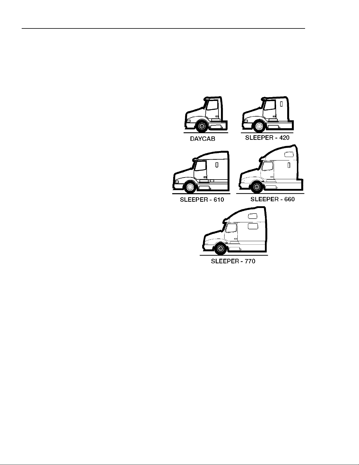
W0001619
VN cab types
Page 8
General Safety Information
Operating the Vehicle
Every vehicle, including heavy duty vehicles, has blind spots. The size of blind
spots varies from driver to driver and from
situation to situation. As a skilled, professional driver,
avoid accidents in turns, lane changes or
other maneuvers. Volvo Trucks North
America, Inc. provides standard equipment
(such as cabs, windshields, window sizes
and mirrors), preferred by most owners and
drivers under most conditions and in most
applications.
you are in the best position to
General Information 3
Never try to operate or work on this
vehicle while under the influence of alcohol. Your reflexes can be affected by
even a small amount of alcohol. Drinking and operating this vehicle can lead
to an accident, causing serious personal
injury or death.
However, due to differences in the size of
drivers, their seating positions, the way that
they use and operate their vehicles, personal preferences and other factors, no
combination of mirrors and other visibility
enhancement devices will eliminate all
blind spots in every situation.
The safe operation of this vehicle is up to
you. Because of your special preferences,
needs and circumstances, you may want to
add extra mirrors and/or other visibility enhancement devices. If so, you should
contact an authorized Volvo Truck dealer to
obtain those parts which best fit your own
personal needs and preferences.
WARNING
All items within the cab must be secured
before the vehicle is set in motion. This
includes, but is not limited to, drinks,
clothes, books, televisions, etc. In the
event of a collision, loose items could
fly around inside the cab. This could
cause personal injury.
Page 9
4 General Information
Operating In Bobtail Mode
Tractors are equipped with a bobtail air
brake proportioning valve which automatically redistributes the braking force between
front and rear axles when not hooked up to
a semitrailer (bobtail operation).
When operating in bobtail mode, the rear
brake chambers receive reduced or proportional brake air pressure. When the tractor
is towing a trailer, the rear brake chambers
will receive full (normal) brake pressure.
NOTE! When operating bobtail, be certain
that glad hands, trailer air hoses, electrical
cable and connectors are properly stowed
and secure. Do not allow them to rub or
chafe on other components.
WARNING
When operating bobtail, the brake
system on the vehicle reduces the possibility of rear wheel brake lockup, except
on full pedal application. When bobtailing, be certain that adequate pedal
pressure is applied. There is no need to
reduce pedal effort. Failure to do so may
result in increased stopping distances.
Page 10
Do Not Overload
This vehicle has been designed and assembled for a maximum gross vehicle weight
rating (GVWR) and a maximum front and
rear axle weights rating (FAWR and
RAWR). The actual rating for this vehicle
can be found on the label attached to the
door frame on the driver’s side. If any of
these three ratings is exceeded and overloading occurs, instability, poor handling,
failure of parts and accelerated wear can
occur.
Under no circumstances should the published GVWR, FAWR, and/or RAWR be
exceeded. Failure to observe these precautions can lead to the loss of vehicle
control, resulting in a crash causing serious personal injury or death.
General Information 5
Do not exceed the load rating of the
tires or the vehicle weight ratings. Overloading may result in tire failure causing
loss of vehicle control, leading to an accident resulting in severe personal injury
or death.
Operating
Before driving this vehicle, locate the instruments and controls, and become
thoroughly familiar with their operation.
After starting and when driving, always
check to make sure that the instrument
readings are normal.
W0001210
Page 11

6 General Information
Reporting Safety Defects
USA
The National Highway Traffic Safety Administration (NHTSA) and Volvo Trucks
North America, Inc. should be informed
immediately if you believe that the vehicle
has a defect that could cause a crash, injury
or death.
Contact NHTSA by calling the Auto Safety
Hotline at 1 (800) 424–9393 (or 366–0123
in the Washington, DC area) or by writing
to: NHTSA, U. S. Department of Transportation, Washington, DC 20590.
1 (800) 424-9393
Canada
Refer consumer complaints to Volvo Trucks
Canada, Inc. or to the Transport Canada Department of Public Complaints, Recalls
and Investigations.
Mexico
Volvo Trucks of Mexico, S.A. de C.V.
should be informed immediately if you believe the vehicle has a defect that could
cause a crash, injury or death. Contact
Volvo Trucks de Mexico by calling or by
writing to: Volvo Trucks de Mexico, S.A.
de C.V., Prol. Paseo de la Reforma 600,
1er. Piso — 121, Col. Santa Fe Peña
Blanca, C.P. 01210, México, D.F.
NOTE! For a listing of other contacts for
information or help, see page 341.
1 (905) 795-1555
01 (800) 90 94 900
Page 12
Modifications to Vehicle
Chassis Frame
Frame side rails are heat treated. No welding is permitted because structural failure
may result. Do not drill through either top
or bottom flanges. A warning label is also
attached to the frame for information.
Drilling is permitted in the frame web in
accordance with a specified hole spacing
pattern. Consult a Volvo Truck dealer to
obtain approved hole spacing dimensions or
refer to the Frame Rail and Cross Member
Service Manual.
General Information 7
W7000519
Frame rail and cross member nuts and bolts
should be checked periodically and tightened to the specified torque if necessary.
Frame Alterations
Under no circumstances can the frame be
cut and an extension piece added to increase the wheelbase. The only alteration
allowed is wheel base shortening, where
the only change in the frame rail is a new
hole pattern drilled for the new location of
the rear suspension.
Welding In Vehicle
Do not weld anywhere in or on the vehicle
before disconnecting batteries, all electronic
control units (ECU) and instrument cluster.
See page 298 for more information. Do not
use oxy/acetylene welding to repair cab
panels. Refer to the service manuals for
specific information.
WARNING
Do not weld on any part of the frame or
drill holes in the top or bottom flanges.
Serious structural damage could occur.
Page 13

8 General Information
Exhaust and Noise Emissions
General
USA
The Federal Clean Air Act, Section 203 (a)
(3), states the following concerning the removal of air pollution control devices or
modification of a certified engine to a noncertified configuration:
“The following acts and the causing thereof
are prohibited:
(3) For any person to remove or render inoperative any device or element of design
installed on or in a motor vehicle or motor
vehicle engine in compliance with regulations under this part prior to its sale and
delivery to the ultimate purchaser, or for
any manufacturer or dealer knowingly to
remove or render inoperative any such design after sale and delivery to the ultimate
purchaser.”
delivery of the vehicle to the ultimate purchaser, and, in addition, no manufacturer or
dealer may make take such action after sale
and delivery of the vehicle to the ultimate
purchaser. The law provides a penalty of up
to $10,000 for each violation.
Modifications, such as reprogramming of
the fuel system so the engine will exceed
the certified horsepower or torque, or removing the mufflers are examples of illegal
changes.
Changes should not be made to a certified
engine that would result in an engine that
does not match the configuration of an engine model that is currently certified to
meet Federal Standards.
Specifically, please note that no person may
make such changes prior to the sale and
Canada
The same conditions that apply in the USA
apply to Canada, with one exception. After
the vehicle is sold to a retail customer, that
is, the end user, the jurisdiction controlling
the emission control devices becomes the
province in which the vehicle is licensed.
No changes should be made that render any
or all of the devices inoperative.
Should the owner/operator wish to make
any changes to the emission control devices, check with the provincial authority
before making any such changes.
Mexico
The same conditions that apply in the USA
apply to Mexico. Refer to the Mexican
Federal Law for Emission Control which
adheres to EPA regulations. No changes
should be made that render any or all of
the emissions control devices inoperative.
Should the owner/operator wish to make
any changes to the emission control devices, check with the state authority before
making any such changes.
Page 14

General Information 9
California Emission Control Warranty Statement
YOUR WARRANTY RIGHTS AND OBLIGATIONS
The California Air Resources Board and Volvo Trucks North America , Inc. (VTNA) are
pleased to explain the emission control system warranty on your vehicle. In California,
new motor vehicles must be designed, built and equipped to meet the State’s stringent
anti-smog standards. Volvo Trucks North America, Inc. must warrant the emission control
system on your vehicle for the periods of time listed below provided there has been no
abuse, neglect or improper maintenance of your vehicle.
Your emission control system may include parts such as carburetor or fuel injection system
and engine computer. Also included may be hoses, belts, connectors and other emissionrelated assemblies.
Where a warrantable condition exists, Volvo Trucks North America, Inc. will repair your
vehicle at no cost to you including diagnosis, parts and labor.
MANUFACTURER’S WARRANTY COVERAGE
This warranty is appliccable for a period of five years, 100,000 miles or 3,000 hours of
operation, whichever first occurs. If an emission-related part of your vehicle is defective,
the part will be repaired or replaced by Volvo Trucks North America, Inc.
This is your emission control system DEFECTS WARRANTY.
OWNER’S WARRANTY RESPONSIBILITIES
As the vehicle owner, you are responsible for the performance of the required maintenance
listed in your owner’s manual. Volvo Trucks North America, Inc. recommends that you retain all receipts covering maintenance on your truck but Volvo Trucks North America, Inc.
cannot deny warranty solely for the lack of receipts or for your failure to ensure the performance of all scheduled maintenance.
You are responsible for presenting your vehicle to a Volvo Trucks North America, Inc.
dealer as soon as a problem exists. The warranty repairs should be completed in a reasonable amount of time, not to exceed 30 days.
As the vehicle owner, you should also be aware that Volvo Trucks North America, Inc.
may deny you warranty coverage if your vehicle or a part has failed due to abuse, neglect,
improper maintenance or unapproved modifications.
If you have any questions regarding your warranty rights and responsibilities, you should
contact Volvo Trucks North America, Inc., Warranty Administration, (336) 393-2000 or
the California Air Resources Board at 9480 Telstar Avenue, El Monte, CA 91731.
Page 15

10 General Information
EMISSION CONTROL SYSTEM WARRANTY
Volvo Trucks North America, Inc. WARRANTS TO THE ORIGINAL OWNER, AND
EACH SUBSEQUENT OWNER, OF A NEW TRUCK POWERED BY A VOLVO
DIESEL ENGINE THAT THE EMISSION CONTROL SYSTEM OF YOUR TRUCK:
1 Is designed, built and equipped so as to conform at the time of sale to all regulations
of the U.S. Environmental Protection Agency and the California Air Resources Board
applicable at the time of the manufacture; and
2 Is free from defects in material and workmanship which will cause the emission con-
trol components not to function as designed for a period of use of 5 years or 100,000
miles or 3,000 hours of engine operation, whichever comes first.
The 5 years/100,000 miles/3,000 hour warranty period shall begin on the date the vehicle
is first delivered to the first retail purchaser or if the vehicle is placed in service as a
demonstrator company vehicle prior to the sale at retail, on the date the vehicle is the first
placed in service.
The emission control system of your new Volvo engine was designed, built and tested using genuine Volvo parts, and the engine is certified as being in conformity with Federal
and California emission control regulations. Accordingly, it is recommended that any replacement parts used for maintenance, replacement or repair without invalidating this
warranty; the cost of such services or or parts, however, will not be covered under the warranty except in an emergency situation. A part not being available or a repair not being
completed within 30 days also constitutes an emergency.
Use of replacement parts which are not of equivalent quality may impair the effectiveness
of emission control systems. If other than Volvo parts are used for maintenance, owner
should obtain assurances that suck parts are warranted by their manufacturer to be equivalent to genuine Volvo parts. However, the use of other than Volvo replacement parts does
not invalidate the warranty on other components, unless such parts cause damage to warranted parts.
Repairs and service covered by the warranty will be performed by an authorized Volvo
Trucks North America, Inc. dealer at his place of business with no charge for parts or labor (including diagnosis) using Volvo parts for the emission control system, that requires
replacement and is covered by the warranty and found defective. In case of an emergency,
where an authorized Volvo Trucks North America, Inc. dealer is not available, repairs may
be performed at any available service establishment or by the owner, using any equivalent
replacement parts and Volvo Trucks North America, Inc. will reimburse the owner for such
repairs (including diagnosis) not to exceed Volvo Trucks North America, Inc’s suggested
retail retail price for the warranted parts and the labor rate appropriate for the geographical
area and the tasks performed.
Replaced parts and paid invoices must be presented to a Volvo Trucks North America, Inc.
dealer for reimbursement.
Page 16

General Information 11
The emissions control parts covered by this Emission Control System Warranty are listed
under "What Is Covered by the Emissions Warranty." You are responsible for the performance of all required maintenance on your new Volvo engine, including maintenance or
repairs needed due to severe operating conditions. Volvo Trucks North America, Inc. will
not deny a warranty claim solely because you have no record of maintenance. However,
Volvo Trucks North America, Inc. may deny a warranty claim if your failure to perform
required maintenance resulted in the failure of a warranted part. Receipts covering the
performance of regular maintenance should be retained in the event questions arise concerning maintenance. The receipts should be transferred to each subsequent owner of the
vehicle with the emission warranted engine.
CUSTOMER ASSISTANCE
Volvo Trucks North America, Inc. wishes to help to assure that the Emission Control System Warranty is properly administered. In the event that you do not receive the warranty
service to which you believe you are entitled under the Emission Control System Warranty,
you should contact Volvo Trucks North America, Inc. Warranty Administration, (336) 393-
2000. The address and telephone number of each Regional Office is in your vehicle
owner’s manual. If you need additional assistance or information concerning the Emission
Control System Warranty, contact: Volvo Trucks North America, Inc., Warranty Administration, (336) 393-2000.
WHAT IS NOT COVERED BY THE EMISSION WARRANTY
This warranty does not cover:
1 Malfunctions in any part caused by any of the following: misuse, abuse, improper
adjustments unless performed by a Volvo Trucks North America, Inc. dealer, modifications, alterations, tampering, disconnection, improper or inadequate maintenance, or
use of fuels not recommended for the engine as described in the owner’s manual.
2 Damage resulting from accident, acts of nature or other events beyond the control of
Volvo Trucks North America, Inc.
3 The replacement of expendable maintenance items such as filters, hoses, belts, oil,
thermostat and coolant made in connection with scheduled maintenance services once
these parts have been replaced. Any parts replaced under warranty before the first required replacement point are warranted for the remainder of the warranty period.
4 Replacement items which are not genuine Volvo parts or not authorized by Volvo
Trucks North America, Inc.
5 Loss of time, inconvenience, loss of use of vehicle or engine, or commercial loss.
6 Any vehicle on which the odometer or hourmeter has been disconnected or the
mileage (or hours) has been altered so the actual usage cannot be readily be deter-
mined.
7 Any vehicle registered and normally operated outside the United States.
Page 17

12 General Information
WHAT IS COVERED BY THE EMISSION WARRANTY
The following is a list of the items that are considered a part of the Emission Control Systems and are covered by the Emission Warranty when installed as original equipment by
Volvo Trucks North America, Inc. on vehicles which were built to conform to Environmental Protection Agency and California Air Resources Board regulations
IMPORTANT - This may not include expendable maintenance items. Emission related
parts requiring scheduled maintenance are warranted until their first scheduled replacement
point.
I. Fuel Injection System
II. Air Induction System
A. Intake Manifold
B. Turbocharge System
C. Charge Air Cooler (Intercooler)
III. Exhaust Manifold
IV. Miscellaneous Items Used in Above Systems
A. Hose, clamps, fittings and tubing
B. Pulleys, belts and idlers
C. Vacuum, temperature, and time sensitive valves and switches
D. Mounting hardware, sealing gaskets and PVC (if applicable)
THIS CALIFORNIA EMISSION CONTROL WARRANTY STATEMENT IN NO WAY
REPLACES, MODIFIES, ALTERS OR SUPERSEDES THE TRUCK WARRANTY CER-
TIFICATE, ITS TERMS AND CONDITIONS, AND ITS
LIMITATIONS AND EXCLUSIONS.
BE CERTAIN YOU READ AND UNDERSTAND ALL WARRANTIES WHICH
ACCOMPANIED YOUR VEHICLE.
NOTE! Warranty coverage is subject to
change without notice. Contact your Volvo
Truck dealer for the current warranty
statement.
Page 18

Noise Emissions
Volvo Trucks North America, Inc. warrants
to the first person who purchases this vehicle for purposes other than resale and to
each subsequent purchaser, that this vehicle
as manufactured by Volvo Trucks North
America, Inc. was designed, built and
equipped to conform, at the time it left the
control of Volvo Trucks North America,
Inc., with all applicable U.S. EPA Noise
Control Regulations.
This warranty covers this vehicle as designed, built and equipped by Volvo Trucks
North America, Inc., and is not limited to
any particular part, component or system of
the vehicle manufactured by Volvo Trucks
North America, Inc. Defects in design, assembly or in any part, component or system
of the vehicle as manufactured by Volvo
Trucks North America, Inc., which, at the
time it left the control of Volvo Trucks
North America, Inc. caused noise emissions
to exceed Federal standards, are covered by
this warranty for the life of the vehicle.
General Information 13
Page 19

14 General Information
Tampering with Noise Control System
Federal law prohibits the following acts or
the causing thereof:
(1) The removal or rendering inoperative by
any person, other than for purposes of
maintenance, repair, or replacement, of any
device or element of design incorporated
into any new vehicle for the purpose of
noise control prior to its sale or delivery to
the ultimate purchaser or while it is in use;
or
(2) the use of the vehicle after such device
or element of design has been removed or
rendered inoperative by any person.
Among those acts presumed to constitute
tampering are the acts listed below:
Air Intake System
Removing or rendering inoperative the air
cleaner or intake piping.
Engine Cooling Fan
Removing or rendering inoperative the fan
clutch.
Removing the fan shroud.
Engine
Removing or altering engine speed programming so as to allow engine speed to
exceed manufacturer’s specifications.
Modifying the parameters of the Engine
Electronic Control Unit.
Page 20

Fuel System
Removing or altering engine speed programming so as to allow engine speed to
exceed manufacturer’s specifications.
Inner Fender Shields and Cab Skirts
Removing shields or skirts.
Cutting away parts of shields, skirts or damaged or loose portions of shields or skirts.
General Information 15
Page 21
16 General Information
Vehicle Data
Identification and Labels
It is extremely important that the correct
vehicle model and serial number are given
whenever replacement parts or service literature are ordered. Using these numbers, as
well as giving the major component model
and serial numbers, will prevent delay and
errors in obtaining the correct material.
Space is given on the rear inside cover of
this manual for noting the main component
model and serial numbers.
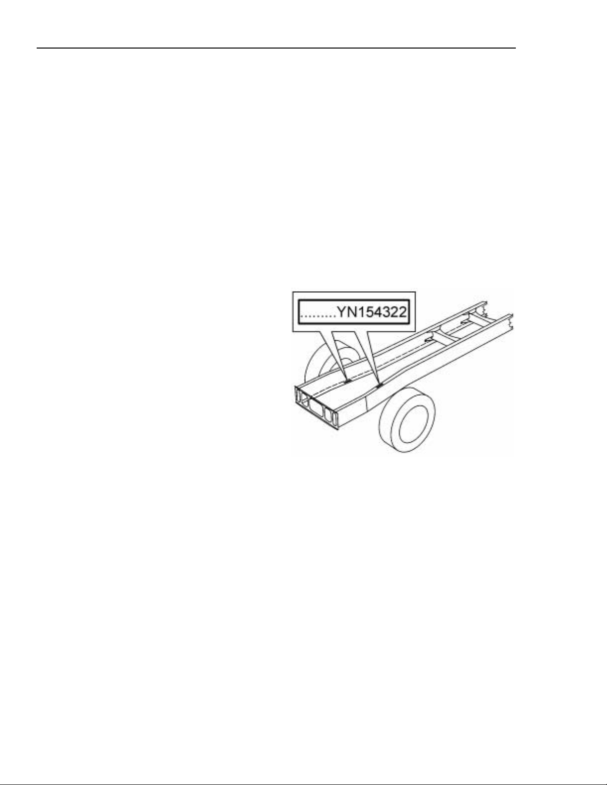
The full 17–digit Vehicle Identification
Number (VIN) is shown on the Vehicle
Identification label located in the door
opening on the driver’s side (see next
page). The 8–digit chassis number is embossed into the bottom flange right hand
side of the frame rail and the top flange left
hand side of the frame rail, 42 inches (1065
mm) back from the front edge of the frame
rail. The use of this number is very helpful
when ordering parts for your vehicle.
Vehicle Order
The Vehicle Order is a complete and detailed record of all data pertaining to the
assembly of the vehicle. It should be filed
in the Owner’s office where it will be readily available for reference. Any changes
made to the vehicle must become a part of
the Vehicle Order and must comply with all
applicable Federal Motor Vehicle Safety
Standards.
W0001995
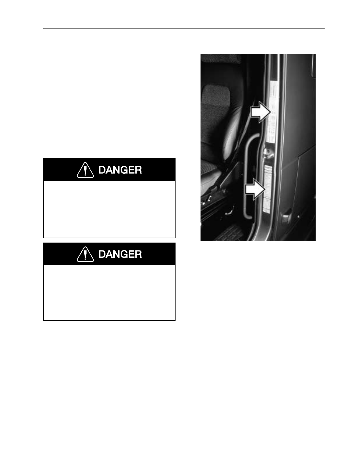
Page 22
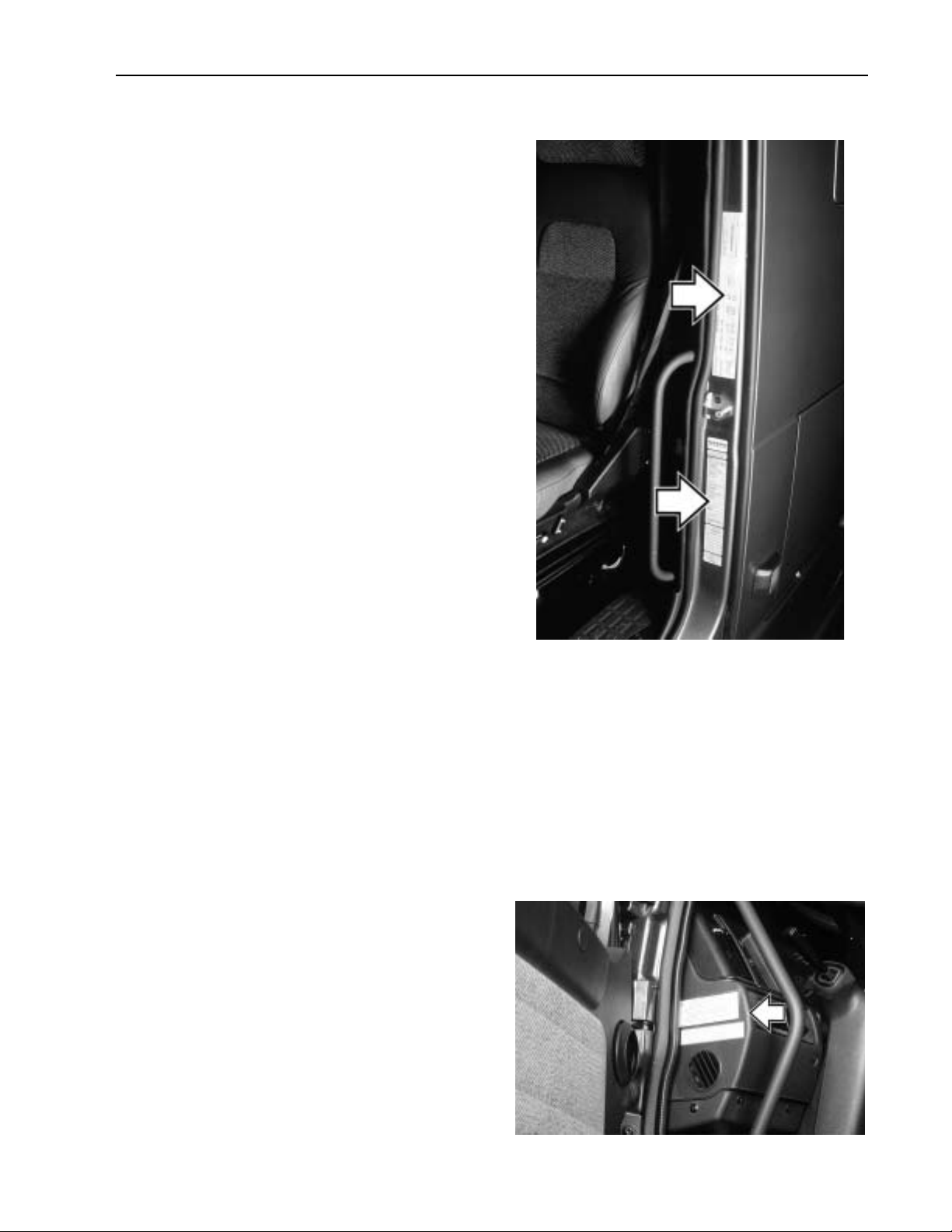
Identification and Certification Labels
There are two labels that are located on the
rear, lower face of the driver side door
frame. These should be part of the vehicle
at all times.
The VIN is shown on the Vehicle Identification label. The VIN includes the vehicle
make, model series, weight class, engine
model, where the vehicle was built and the
vehicle serial number. This label also
shows the truck model designation, major
component model and serial number, cab
model and serial number, cab and chassis
paint colors, and color numbers.
On the upper part of the door frame is the
Certification label showing the axle and
load ratings for the vehicle as it was built.
Do not exceed these ratings by overloading.
General Information 17
NOTE! To deter tampering with the original build information, the information on
the label will be destroyed if label is
removed. If for any reason a label is damaged, contact your Volvo Truck dealer for a
replacement.
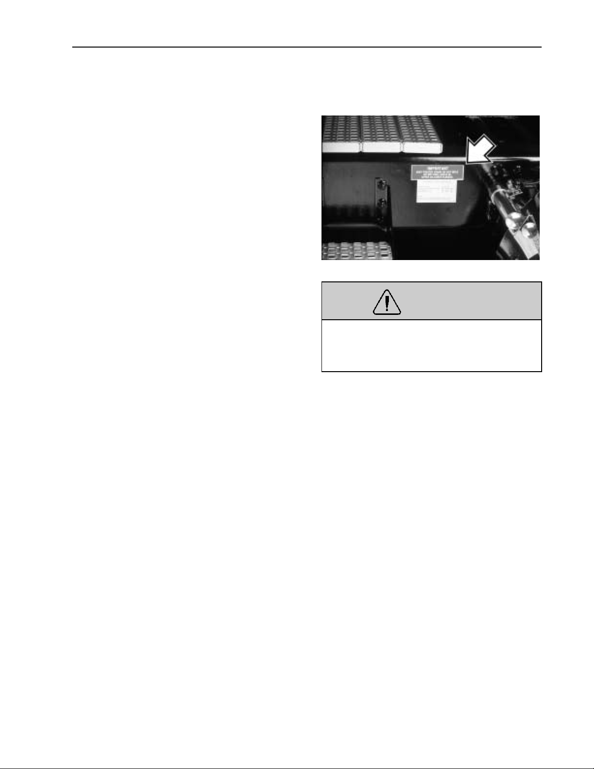
Noise Emission Control
A Noise Emission Control label is located
on the left end of the dash. It is the
Owner’s responsibility to maintain the vehicle so that it conforms to EPA regulations.
Refer to page 14 for a listing of what constitutes tampering with the Noise Emissions
Control.
W0001210
W0001458
Page 23
18 General Information
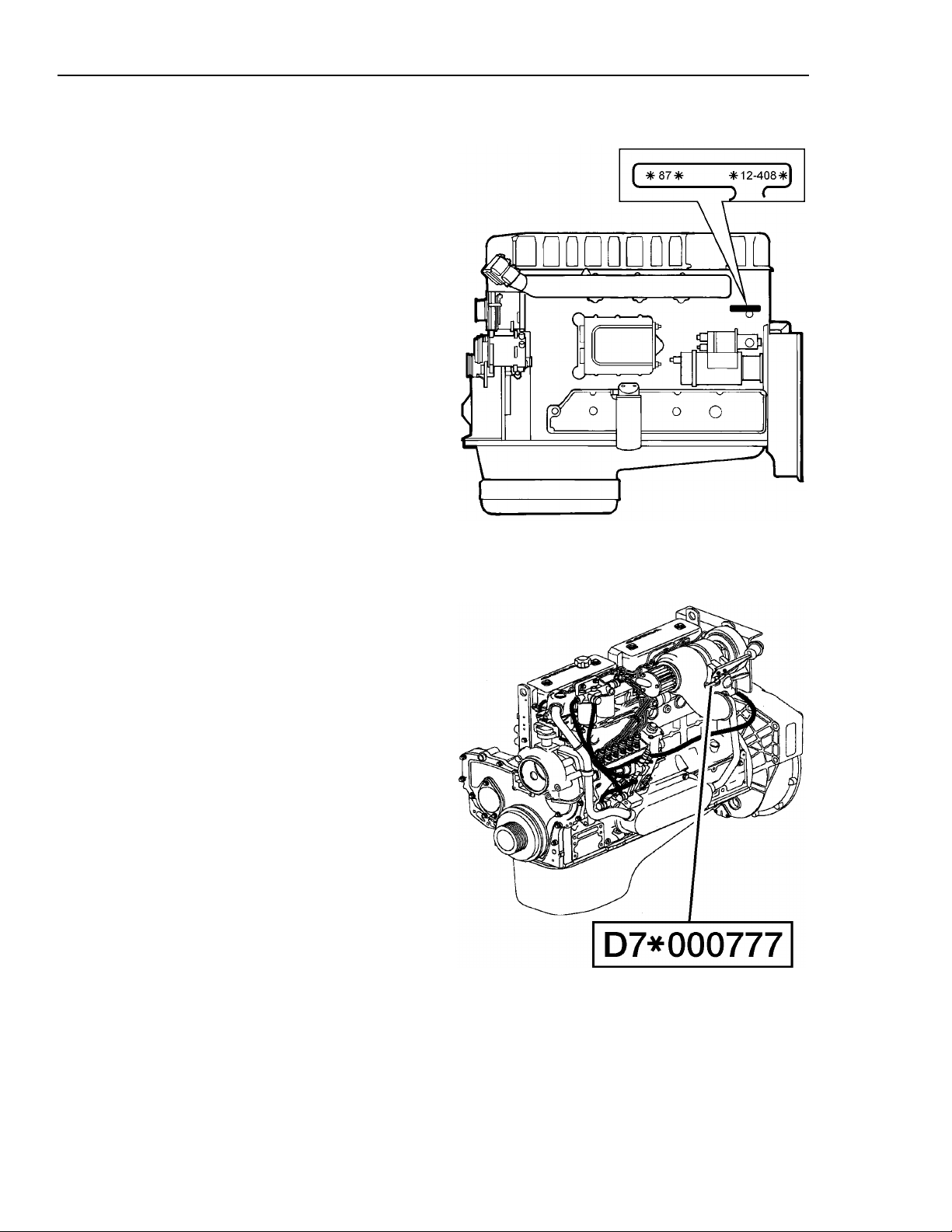
Components
The Volvo D12 engine serial number is located on the rear, left side of the cylinder
block.
There is also a label on the engine electronic control unit that shows the engine
serial number.
The Volvo D7 engine serial number is located on the rear, left side of the cylinder
block.
There is also a label on the rear valve cover
that shows the engine serial number.
W0001529
W2002707
Page 24
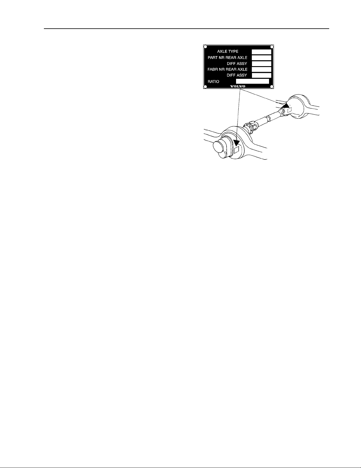
The rear axle model and serial number is
located on the right side of the transfer gear
housing on the tandem front axle. It is located on the left side of the differential
housing on the tandem rear axle and on the
right side of the single axle.
General Information 19
W4000894
Page 25
20 Vehicle Access
Cab Doors and Door Lock
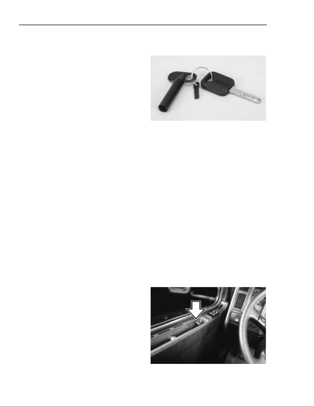
The cab door is unlocked with the same
key used for the ignition lock. Keys can be
made to fit only one vehicle or all the vehicles in a fleet of Volvos. A tool for
changing bulbs in the instrument cluster is
included on the keychain.
The key fits in the door lock either way.
Insert the key and turn it 1/4 turn counterclockwise to unlock or clockwise to lock
the door.
NOTE! The vehicle is delivered with 2
identical keys. If more keys are needed,
order them through your Volvo Truck authorized dealer. The keys are laser cut and
require a special machine for copying,
available through the dealer. Record the key
code and keep it in a secure place. A new
key can be made if the keys are lost.
W0001231
Key code at the end of keychain
The door locks are mechanically or electrically operated. The lock is activated by
either the key from the outside or the door
lock handle from the inside. With mechanical locks, only one door can be
locked/unlocked at a time. With electrical
locks, both doors will be locked/unlocked
by operating either the key or the inner
door lock handle on either side.
To lock either door from the inside, push
the door lock handle forward. The handle
will stay in place, indicating the door is
locked. It can be unlocked without opening
the door by moving the door lock handle to
the middle position.
No door can be locked while it is still
open. The door must be closed for the lock
to work. In the event of a power failure the
electrical lock system reverts back to a mechanically functioning system.
W8001462
Page 26
The door has a position lock that enables
the door to remain open in two different
positions. An indented bar is holding the
door at approximately 30
open position at approximately 85
and in the fully
.
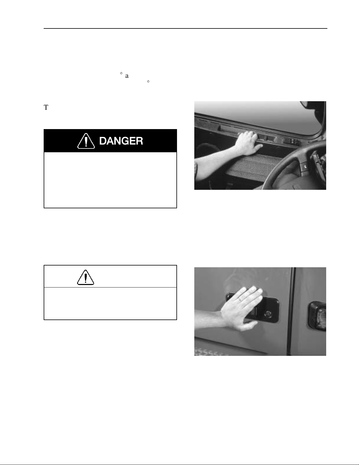
To close the door from the inside, place the
hand in the handhold and pull the door in.
To lessen the chance of being thrown
from the vehicle in case of an accident,
always lock the door and wear the safety
belt while driving. Failure to do so can
cause serious personal injury or death if
involved in an accident.
Vehicle Access 21
W8001854
CAUTION
Do not shut the door by pushing on the
door panel. Hard pushing may distort
the metal in the door panel.
To close the door from the outside, place
the hand flat against the door lock area and
push the door shut.
W8001853
Page 27
22 Vehicle Access
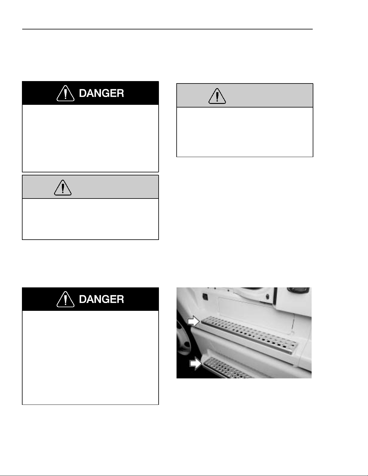
Cab Entry and Exit
General
WARNING
Do not stand on the steps or any other
part of the vehicle while it is in motion.
The steps and the back of cab access
deck plates are only for entering/exiting
the vehicle and not for riding on. Failure
to heed this warning can result in serious personal injury or death.
WARNING
Wearing shoes with soles that are dirty
or wet increases the chance of slipping
and falling. Be careful when entering the
cab with dirty or wet soles.
Both the operator and passenger should
exercise caution when entering or exiting
the cab. Use the steps and grab handles
to safely get in and out of the cab to
prevent injuries related to a slip and fall.
Steps are designed to be slip resistant
and to provide a stable surface for
entering or exiting the cab. However, accumulation of ice, dirt, lubricants, etc.
on the steps can make entering or exiting hazardous. Always make sure the
steps are free from slippery substances.
Failure to follow this guideline may result in a fall that can cause serious
personal injury or death.
The steps on the vehicle are designed to
conform with the requirements of 49 CFR
399. You should familiarize yourself with
this Federal regulation.
W8000928
Page 28

Vehicle Access 23
General Entry Guidelines
1 Always have three limbs (one foot and
two hands or two feet and one hand)
in contact with the vehicle at all times
when entering or exiting the cab or the
area behind the cab.
2 Be certain you have a firm handhold
and/or stable foot position before
transferring weight to that position. For
example, do not start to put weight on
a foot until you are certain your foot is
properly on the step and will not slip
when you transfer your weight.
3 Do not climb on top of the frame, fuel
tanks or storage boxes to make trailer
hook-ups.
4 If the vehicle is equipped with air fair-
ings, do not use the side mounted
fairing (wind deflector) brackets and
braces as steps or grab handles.
box cover is properly fastened before
stepping.
9 Do not jump from the cab or from the
steps to the ground.
10 Always face the cab when entering or
exiting.
11 Do not hold anything in your hands
when entering or exiting the cab or the
area behind the cab. Log books, cups,
clipboards, jackets, luggage and the
like can be placed on the cab floor or
rear deck plate before entering or exiting.
12 Be sure to disconnect the safety belt
before exiting the cab.
13 Be sure that the safety belt is fully re-
tracted and out of the way prior to
entering or exiting the cab.
5 Be certain that the grab handles are
clear of snow, mud, ice or other substances that could make them slippery
before using them. Do not use steps or
grab handles if they are slippery or
damaged.
6 Be certain that all grab handles, steps
and related parts are in good working
condition. Any defects should be reported and repaired before using the
grab handles and steps.
7 Do not step on the curved surface of
the fuel tanks. They may be slippery
from snow, mud, ice, water, spilled
fuel or other slippery substances.
8 If a step is mounted to the top of the
battery box, be certain that the battery
14 Do not put your foot on any surface
that does not have slip resistant, self
cleaning material. If there is no step
material, the surface may be slippery
and you could fall.
15 Before entering or exiting, be certain
that the soles of your shoes/boots are
free from grease, mud or any other
substance which could make them
slippery.
16 Always put the foot flat on the top of
the step. Do not place your foot on the
side or edge of the step.
BE SURE TO FOLLOW ALL OF
THESE INSTRUCTIONS BEFORE ENTERING O
THE AREA BEHIND THE CAB.
R EXITING THE CAB OR
Page 29
24 Vehicle Access
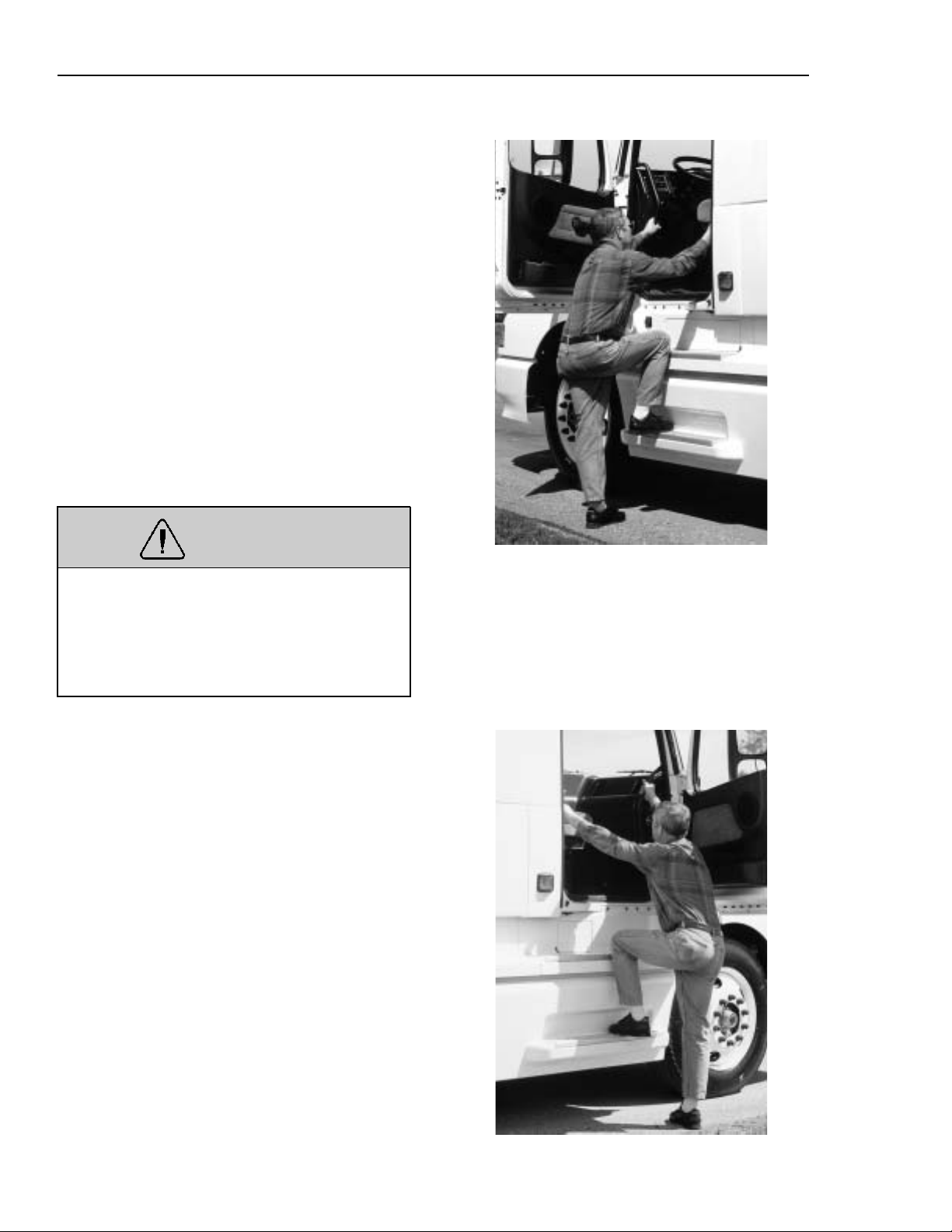
Driver Side Entry/Exit
Open the door. Place any hand-carried
items on the cab floor. Grasp the right grab
handle with your right hand and the left
grab handle with your left hand. Put your
right foot fully on the bottom step and pull
yourself up to the opening.
Slide hands up on the handles, if necessary.
Put your left foot on the top step and step
up. Step into the cab with your right foot
first.
To exit, reverse the process. Do not attempt
to exit the cab while carrying any items in
your hands.
WARNING
On vehicles without side fairings, always make sure that the battery box
cover is securely fastened before stepping up. Failure to fasten the cover may
lead to personal injury.
Passenger Side Entry/Exit
Open the door. Place any hand-carried
items on the cab floor. Grasp the left grab
handle with your left hand and the right
grab handle with your right hand. Put your
left foot fully on the bottom step and pull
yourself up to the opening.
Slide hands up on the handles, if necessary.
Put your right foot on the top step and step
up.
W0001223
Step into the cab with your left foot first.
To exit, reverse the process. Do not attempt
to exit the cab while carrying any items in
your hands.
W0001228
Page 30
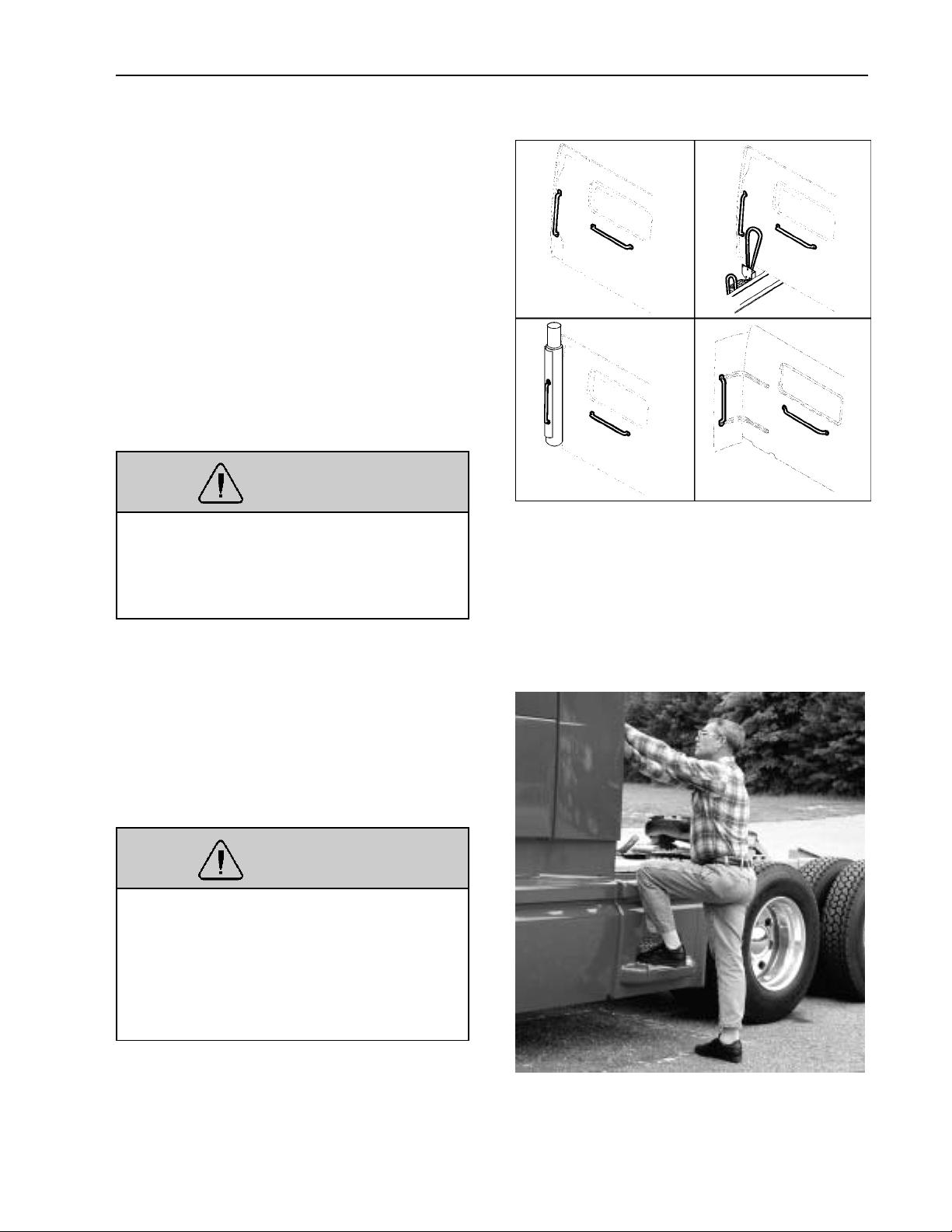
Behind the Cab Entry
When trailer air and electrical connections
can not be coupled from the ground, Federal Regulations require commercial
carriers to provide back-of-cab access steps,
grab handles and plates.
Depending on what option is chosen, grab
handles are available in many variations. In
each case, make sure to always have three
limbs (one foot and two hands or two feet
and one hand) in contact with the vehicle at
all times when entering or exiting the area
behind the cab.
WARNING
Wearing shoes with soles that are dirty
or wet increases the chance of slipping
or falling. Be careful when entering the
back-of-cab area with dirty or wet soles.
Vehicle Access 25
W8001363
Grasp the grab handle to the left with both
hands. Put the left foot onto the bottom
step and pull yourself up. Put the right foot
on the top step and step onto the deck plate
with the left foot.
WARNING
Always perform trailer hook-ups while
standing on the ground. Do not climb
on top of fuel tanks or frame rails to
hook up or disconnect trailer air lines
and electrical cord, or serious injuries
could result from a slip and fall.
W9000077
Page 31

26 Vehicle Access
Stand on the ground when connecting the
air and electrical connections to the trailer.
W5000713
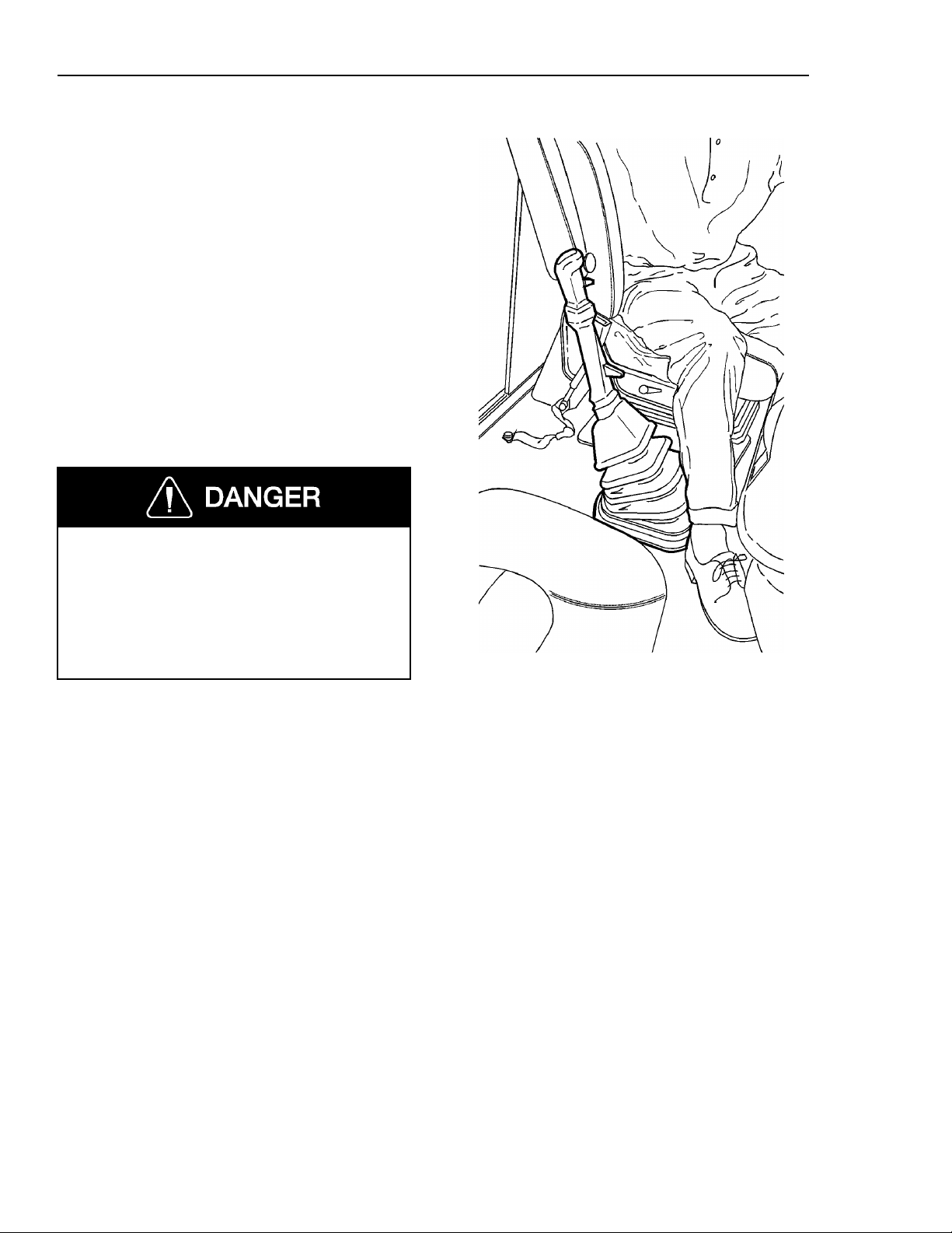
Entering Sleeper From Seat
Standard Gear Lever
When moving from the driver seat to the
sleeper section, follow this procedure:
Make sure the parking brakes are set
•
Place the gear shift lever in a gear po-
•
sition toward the rear of the vehicle
If equipped with an adjustable steering
•
column, move the steering wheel up
and forward
Place the left hand on the steering
•
wheel and the right hand on the top of
the gear lever
Move the right foot out to the middle
•
of the floor
Lift the upper body, supported by the
•
hands on the steering wheel and the
gear lever and step out from the seat
area.
W8002037
Page 32

Folding Gear Lever (option)
When moving from the driver seat to the
sleeper section, follow this procedure:
Make sure the parking brakes are set
•
To release the gear lever, pull the lever
•
toward the seat and press on the knob
downward in a straight line.
Vehicle Access 27
W4001388
Twist the lever counterclockwise while
•
holding pressure on the knob. When
releasing the pressure, the
springloaded lever will be pushed up
out of the locked position.
Lift and fold the gear lever straight
•
back, parallel with the seat. It will
come to rest in the folded position.
W4001389
NOTE! If the lever is not folded
straight back, it may not be able to
travel the full distance.
W4001390
Page 33
28 Vehicle Access
If equipped with an adjustable steering
•
column, move the steering wheel up
and forward
Place the left hand on the steering
•
wheel and the right hand on the top of
the dash
Move the right foot out to the middle
•
of the floor
Lift the upper body, supported by the
•
hands on the steering wheel and the
dash and step out from the seat area.
When locking the gear lever in place
again, follow the procedure on page 271.
Failure to lock the gear lever properly
into place can cause loss of control of
vehicle, leading to serious personal injury or death.
W4001391
Page 34
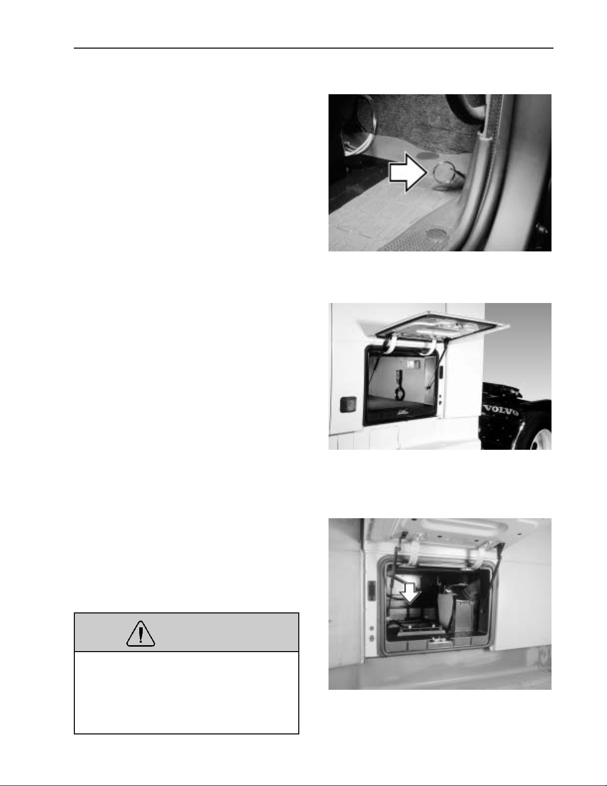
Luggage Compartment
To gain access to the luggage compartments, there is a pull-ring connected to the
lock, located at the lower rear corner of the
cab door opening on each side. Pull ring to
unlock the door. The lock has a safety catch
that will hold the door in place, even if the
door is not fully locked. To open door, hold
pull-ring out while pulling the door out.
The door swings out from the bottom on
hinges mounted on the top. To assist in
opening and to hold the door open, there
are two compressed gas cylinders mounted
on each door. The door will swing up by itself when pulled out a short distance and
then released. If the light switch is set on
automatic, the light will come on when the
door opens.
Vehicle Access 29
W8000984
Safety equipment and tow hooks are stored
in the luggage compartments. If equipped,
the sleeper heater and air conditioning unit
is located in the passenger side luggage
compartment.
WARNING
Always place heavy objects in the luggage compartment. Sudden stops or
sudden turns could cause personal injury
if heavy objects fall from overhead storage shelves.
W8001073
W1000139
Page 35
30 Vehicle Access
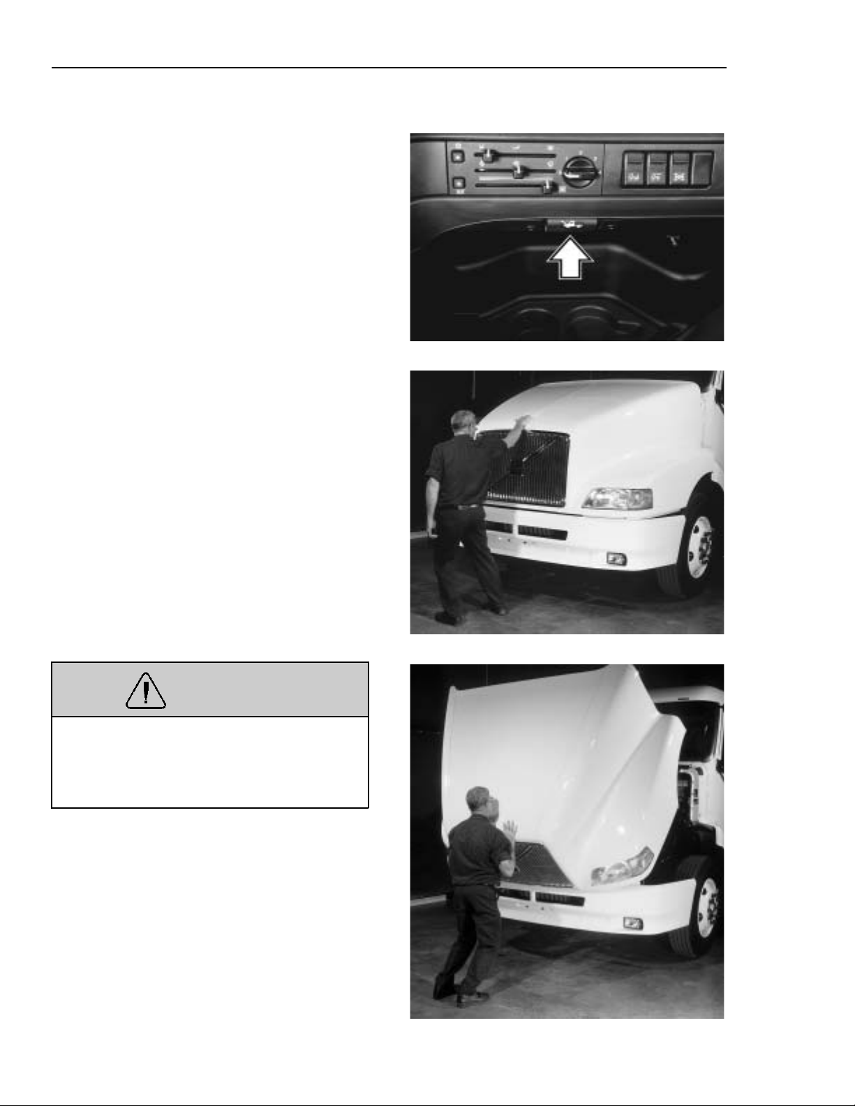
Hood
The hood is locked down by two latches,
one on each side of the back end of the
hood. The latches are operated by a handle
on the bottom edge of the dashboard.
Pull the bottom of the handle out to release
hood. The hood will be raised about two
inches off its resting position and remain
there.
Make sure the hood can be opened fully
without hitting anything. Stand sideways in
front of the hood with feet in line with the
vehicle. Place feet well apart and grasp the
recessed handle in the front part of the
hood. Transfer the body weight by leaning
away from the hood. Lift the hood until it
is past the balance point. Release the hood
and let it complete the opening movement
unaided.
Two restraint cylinders will engage during
the last part of the opening. The cylinders
will slow and dampen the hood down to its
resting position.
WARNING
Make sure that no one is in the way of
the hood when closing. The hood could
injure a person in the way while being
lowered.
W8000986
W8000982
To close the hood, stand with feet well
apart and place the hands along the front
edge of the hood. Bend the knees and let
the leg muscles do the work when lifting.
Raise the hood up to the halfway point.
Carefully guide the hood down with
enough speed that the hood latches lock the
hood in place when it comes to its normal
resting position.
W8000983
Page 36
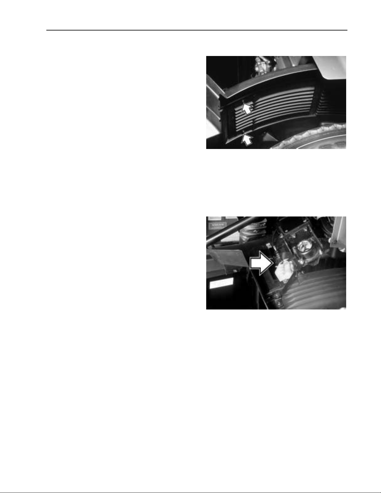
Manual Hood Opening
In the event of a malfunction in the hood
opening mechanism, the hood latches can
be manually operated through an opening
in the wheelwell splash shield. The opening
is normally covered by a plate.
To access the opening, remove the two
screws using a T30 Torx screwdriver. Remove the cover plate.
Vehicle Access 31
W8002389
The hood latch can now be accessed
through the hole. Operate the latch manually by pushing the lever in toward the
engine. Do the same on the other side.
W8000981
Page 37

32 Pre-Trip Inspection and Daily Maintenance
General
Before working on or inspecting a vehicle, set the parking brakes, place the
transmission in neutral and block the
wheels. Failure to do so can result in unexpected vehicle movement and can
cause serious personal injury or death.
Safety is the most important and obvious
reason for doing a pre-trip inspection. Federal and state laws require inspection done
by the driver. Federal and state inspectors
also inspect commercial vehicles. An unsafe vehicle can be placed “out of service”
until the driver or owner corrects the
deficiency. Owners and operators should familiarize themselves with sections 49 CFR
396.11 and 396.13 concerning Federal requirements for vehicle inspection. Certain
other laws may also apply.
Section 49 CFR 396.13 states that all motor
carrier drivers must complete a written report at the end of each work day for each
vehicle operated, covering most of what is
covered in the pre-trip list. The report
should list all defects or deficiencies discovered by the driver. Doing a pre-trip
inspection prepares for the end-of-work report.
Starting on the next page are suggested
guidelines to be used in performing truck,
tractor and trailer pre-trip inspections. De-
pending on the application of the vehicle
being used, these guidelines should be
modified to include other necessary inspection points. For example, steps and grab
handles should be checked daily on refuse
trucks because the operator is getting in
and out of the cab more frequently.
If any component or system does not pass
this inspection, it must be corrected before
operating the vehicle. Whenever equipment
requires adjustment, replacement, repair or
lubrication, refer to the Service Manuals or
contact a Volvo Truck dealer for the correct
procedures, specifications and intervals.
Take your time going through the pre-trip
inspection. Remember that a careful pre-trip
inspection saves time by eliminating unscheduled stops for correcting a faulty item.
The following information has been
provided by the American Trucking Association as developed by the D.O.T. Office of
Motor Carriers (BMCS).
Page 38
Pre-Trip Inspection and Daily Maintenance 33
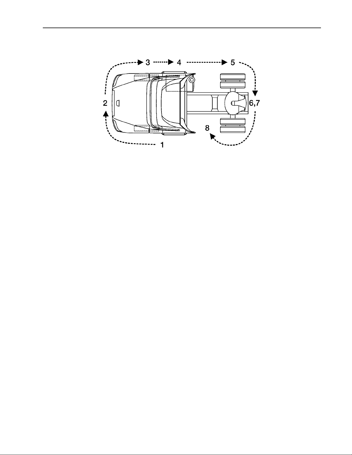
Pre-Trip Inspection Quick List
Inspect the vehicle in a circular manner as shown in the
illustration. Numbers between parentheses in the list, refer to pages in this manual where component function
and necessary inspection is explained in greater detail.
W0001230
Approaching the Vehicle
Check under the vehicle for oil, fuel,
•
coolant leaks or other signs of damage.
Check body surfaces for signs of
•
breaks or damage.
Preparation
Open drain cocks on air tanks to let
•
the tanks drain ( page 283).
Chock wheels on vehicle and, if
•
hooked up, trailer.
Close air tank drain cocks.
•
Start the engine and let the air pres-
•
sure build up to normal ( page 273).
Stop engine.
Switch on parking lights and four-way
•
flashers ( page 99).
Apply parking brakes ( page 278).
•
Release the hood latches ( page 30).
•
Raise hood.
Step 1: Left Side Of the Cab
Left Front Wheel
Check condition of wheel rim. Espe-
•
cially look for cracks, missing
lockrings, bent or broken studs,
clamps or lugs.
Check condition of tire: properly in-
•
flated, no serious cuts, bulges, tread
wear or any signs of misalignment;
valve stem not touching wheel, rim or
brake drum; valve cap in place.
Check wheel bearing and hub: no ob-
•
vious leaking on outside or inside
wheel. Verify correct oil level in hub.
Left Front Suspension
Check condition of spring, spring
•
hangers, shackles, U-bolts: no cracks,
breaks or shifting.
Check shock absorber condition.
•
Page 39

34 Pre-Trip Inspection and Daily Maintenance
Step 1: Left Side Of the Cab (cont.)
Left Front Brake
Condition of brake drum. With brakes
•
released, look for a noticeable gap between lining and drum (This check
cannot be made if dust covers are in
place).
Condition of brake air hose.
•
Check brake chamber mounting bolts
•
and bracket.
Check slack adjuster and chamber
•
pushrod travel.
Condition of Front Axle and Steering System, Left Side
No loose, worn, bent, damaged or
•
missing parts.
Under Hood, Left Side
Check coolant hose condition.
•
Lights and Reflectors
Lower hood and inspect parking,
•
clearance and identification lights on
hood and cab. They should be clean,
operating and of the proper color.
Reflectors clean and proper color.
•
Turn on headlights. High and low
•
beams should be operating and lenses
clean. If equipped, check daytime running lights.
Left and right front turn signal lights
•
clean, operating and proper color.
Raise hood.
Grille
Check that charge air cooler and radia-
•
tor or bugscreens are clean and
undamaged.
Check condition of fan drive belts.
•
Check engine and surrounding areas
•
for coolant, oil and fuel leaks.
Check wiring harnesses for signs of
•
damage.
Step 2: Front Of Cab Area
Condition of Windshield
Check for damage and clean if dirty
•
( page 48 ).
Check windshield wiper arms for
•
proper spring tension.
Check wiper blades for any damage,
•
“dead” rubber and securement to arm.
Step 3: Right Side Of Cab Area
Right Front Wheel
Check condition of wheel rim. Espe-
•
cially look for cracks, missing
lockrings, bent or broken studs,
clamps or lugs.
Check condition of tire: properly in-
•
flated, no serious cuts, bulges, tread
wear or any signs of misalignment;
valve stem not touching wheel, rim or
brake drum; valve cap in place.
Check wheel bearing and hub: no ob-
•
vious leaking on outside or inside
wheel. Verify correct oil level in hub.
Page 40

Pre-Trip Inspection and Daily Maintenance 35
Step 3: Right Side Of Cab Area (cont.)
W0001230
Under Hood, Right Side
Right Front Suspension
Check condition of spring, spring
•
hangers, shackles, U-bolts: no cracks,
breaks or shifting.
Shock absorber condition.
•
Right Front Brake
Condition of brake drum. With brakes
•
released, look for a noticeable gap between lining and drum (This check
cannot be made if dust covers are in
place).
Condition of brake air hose: check for
•
any chafing.
Check brake chamber mounting bolts
•
and bracket.
Check slack adjuster and chamber
•
pushrod travel. With brakes applied or
released, look for conspicuously different positions of the slack adjusters.
Condition of Front Axle and Steering System, Right Side
No loose, worn, bent, damaged or
•
missing parts.
Check condition of coolant and heater
•
hoses.
Check condition of fan drive belts.
•
Check engine and surrounding areas
•
for coolant, oil and fuel leaks.
Check fuel separator sight glass and
•
drain if necessary. Check for leaks.
Check wiring harnesses for signs of
•
damage.
Check air filter with brackets and
•
hoses for loose connections or damage. Check filter gauge, if mounted on
the filter.
Step 4: Right Saddle Tank Area
Right Fuel Tank(s)
Securely mounted and not damaged or
•
leaking.
Fuel lines secure and not leaking.
•
Check that shut-off valves are open.
Tank(s) full of fuel. Cap on and secure.
•
Page 41

36 Pre-Trip Inspection and Daily Maintenance
Condition of Visible Components
Rear of engine: not leaking.
•
Transmission: not leaking. If equipped
•
with oil cooler, check for leaks or that
air-to-air cooler is not blocked.
Check drive shaft.
•
Exhaust system: secure, not leaking,
•
not touching wires, fuel or air tubing.
Frame and cross members: no bends,
•
cracks or breaks.
Air tubing and electrical wiring: se-
•
cured against snagging and chafing.
Step 5: Right Rear Vehicle Area
Dual Wheels, One Or Two Axles
Check condition of wheels and rims.
•
Especially look for cracks, missing
lockrings, bent or broken spacers,
studs, clamps or lugs.
Suspension
Check condition of springs (leaf or
•
air), spring hangers, shackles and Ubolts.
Axle alignment.
•
Brakes
Condition of brake drums. With brakes
•
released, look for a noticeable gap between lining and drum (This check
cannot be made if dust covers are in
place).
Condition of brake hoses: check for
•
any chafing.
Check brake chamber mounting bolts
•
and brackets.
Check slack adjusters and chamber
•
push rod travel. With brakes applied or
released, look for conspicuously different positions of the slack adjusters.
Check spring brakes.
•
Check condition of tires: properly in-
•
flated, no serious cuts, bulges, tread
wear or any signs of misalignment;
valve stems not touching wheels, rims
or brake drums; valve caps in place
and no objects stuck between the
wheels.
Check that both tires are of same type,
•
for example, not mixed radial and bias
type and that their circumferences are
matched.
Check wheel bearing and hub: no obvi-
•
ous leaking on outside or inside wheel.
Step 6: Rear Of Vehicle Area
Frame Area
Frame or cross members not bent,
•
cracked or otherwise damaged or
missing.
Check that air tubing and electrical
•
lines are properly secured to the frame
with no damage or chafing.
Lights and Reflectors
Tail lights, brake lights and turn signal
•
lights: operating, clean and proper
color.
Page 42

Pre-Trip Inspection and Daily Maintenance 37
Step 7: Coupling System Area
Fifth Wheel
Securely mounted to the frame.
•
No missing or damaged parts.
•
Check that trunnion and plate are
•
properly lubricated ( page 318).
Sliding Fifth Wheel
Mechanism not worn, bent, damaged
•
or parts missing ( page 320).
Properly lubricated.
•
W0001230
Step 8: Left Saddle Tank and Left Rear
Vehicle Wheels Area
Dual Wheels, One Or Two Axles
Check condition of wheels and rims.
•
Especially look for cracks, missing
lockrings, bent or broken spacers,
studs, clamps or lugs.
Check condition of tires: properly in-
•
flated, no serious cuts, bulges, tread
wear or any signs of misalignment;
valve stems not touching wheels, rims
or brake drums; valve caps in place
and no objects stuck between the
wheels.
All locking pins present and locked in
•
place.
If air operated: no air leaks.
•
Air Tubing and Electric Lines Visible From
This Point
Should be secure from dangling.
•
Both air lines and electric line should
•
be free from damage, oil and grease.
Check that both tires are of same type,
•
for example, not mixed radial and bias
type and that their circumferences are
matched.
Check wheel bearing and hub: no obvi-
•
ous leaking on outside or inside wheel.
Suspension
Check condition of springs (leaf or
•
air), spring hangers, shackles and
U-bolts, no cracks, breaks or shifting.
Page 43

38 Pre-Trip Inspection and Daily Maintenance
Brakes
Condition of brake drums. With brakes
•
released, look for a noticeable gap between lining and drum (This check
cannot be made if dust covers are in
place).
Condition of brake hoses: check for
•
any chafing.
Check brake chamber mounting bolts
•
and brackets.
Check slack adjusters and chamber
•
push rod travel. With brakes applied or
released, look for conspicuously different positions of the slack adjusters.
Check spring brakes.
•
Condition of Visible Components
Left Fuel Tank(s)
Securely mounted and not damaged or
•
leaking.
Fuel lines secure and not leaking.
•
Check that shut-off valves are open.
Tank(s) full of fuel. Cap on and secure.
•
Battery Area
Open the battery box ( page 294). Bat-
•
tery box securely mounted to vehicle.
Batteries secured against movement
•
( page 294).
Battery cases not broken or leaking.
•
Battery cables free from damage.
Tops of batteries and terminals clean
•
and free from foreign material.
Transmission: not leaking.
•
Drive shaft: looks OK.
•
Exhaust system: secure, not leaking,
•
not touching wires, fuel or air tubing.
Frame and cross members: no bends,
•
cracks or breaks.
Air tubing and electrical wiring: se-
•
cured against snagging and chafing.
If equipped, replace battery lid and
•
make sure it is securely fastened
( page 295).
Page 44

In the Cab
Pre-Trip Inspection and Daily Maintenance 39
W0001230
Check steps and grab handles for
•
looseness or breakage ( page 23).
Also, clean them if there is any substance that makes them slippery, which
makes cab entry/exit hazardous.
Start the engine. If equipped, check
•
that exhaust rain cap opens when accelerating engine.
Check gauges and telltale light func-
•
tion ( page 85).
Check function of low air warning
•
( page 91). Check the Graphic Display
for any fault codes ( page 114).
Check clutch function ( page 269). If
•
equipped, check for clutch brake function.
Check windshield wipers and washers
•
( page 47) and horns, including backup alarm, if equipped.
Check climate control and defroster
•
( page 174). If equipped, check mirror
heater.
Check condition of warning triangles,
•
fire extinguisher and flares ( page 68).
Adjust the seat ( page 195). Check
•
mirror adjustment.
Check safety belts for function and
•
damage ( page 55).
Apply service brakes. After initial
•
drop, pressure should hold steady, or
increase slightly, with engine at idle.
Check steering wheel for excessive
•
free play.
Check for loose items in the cab. Se-
•
cure them if necessary.
Clean inside windshield, door win-
•
dows and instruments. Clean mirrors.
Page 45

40 Pre-Trip Inspection and Daily Maintenance
Hooking Up To Trailer
Hook-up Preparation
Check kingpin and mounting plate on
•
trailer, free from wear, bends or damage.
Chock trailer wheels.
•
Fifth Wheel Or Trailer Hitch
No visible space between fifth wheel
•
and trailer ( page 326).
Locking jaws around the shank and
•
not the head of kingpin ( page 326).
Release lever properly seated and
•
safety latch/lock engaged ( page 327).
Check all connections to dolly or
•
trailer hitch and safety chains are secured.
Check function of trailer air supply
•
valve and trailer brakes.
Sliding Fifth Wheel
Check that fifth wheel is not so far
•
forward that the tractor frame will
strike the landing gear during turns.
Page 46

Pre-Trip Inspection and Daily Maintenance 41
NOTE! Refer to the trailer manufacturer’s
manual for specific information on the
trailer checks.
W0001361
Step 9: Trailer Front Area
Air and Electrical Connections
Glad hands properly mounted, free
•
from damage and not leaking.
Trailer cord receptacle properly
•
mounted, free of damage; plug properly seated and safety catch engaged
to prevent accidental disconnect.
Air and electrical lines properly se-
•
cured against tangling, snagging and
chafing with sufficient slack for turns.
Step 10: Right Side of Trailer Area
Landing Gear or Dolly Area
Fully raised; no missing or damaged
•
parts.
Crank handle present and secured.
•
If power operated, no air/hydraulic
•
leaks.
Spare Wheel(s)
Carrier or rack not damaged.
•
Spare wheel securely mounted in rack.
•
Tire and wheel condition adequate for
•
a spare: proper size, properly inflated.
Lights and Reflectors
Trailer side clearance lights: clean, op-
•
erating and proper color.
Reflectors clean and proper color.
•
Frame and Body
Frame and crossmembers not bent,
•
cracked, damaged or missing.
Proper placarding.
•
Body parts not damaged or missing.
•
Page 47

42 Pre-Trip Inspection and Daily Maintenance
Step 11: Right Rear Trailer Wheel
Dual Wheels, One Or Two Axles
Check condition of wheels and rims.
•
Especially look for cracks, missing
lockrings, bent or broken spacers,
studs, clamps or lugs.
Check condition of tires: properly in-
•
flated, no serious cuts, bulges, tread
wear or any signs of misalignment;
valve stems not touching wheels, rims
or brake drums; valve caps in place
and no objects stuck between the
wheels.
Check that both tires are of same type,
•
for example, not mixed radial and bias
type and that their circumferences are
matched.
tween lining and drum (This check
cannot be made if dust covers are in
place).
Condition of brake hoses: check for
•
any chafing.
Check brake chamber mounting bolts
•
and brackets.
Check slack adjusters and chamber
•
push rod travel. With brakes applied or
released, look for conspicuously different positions of the slack adjusters.
Check spring brakes.
•
Step 12: Rear of Trailer Area
Lights and Reflectors
Check wheel bearing and hub: no obvi-
•
ous leaking on outside or inside wheel.
Suspension
Condition of springs (leaf or air),
•
spring hangers, shackles and U-bolts.
Axle alignment.
•
Condition of torque rod arms.
•
If equipped with sliding axles, check
•
position and alignment. Look for damaged, worn or missing parts, all locks
present, fully in place and locked.
Flexible air tubing not cracked, cut,
•
crimped or otherwise damaged. Secured against tangling, dragging and
chafing.
Brakes
Rear clearance, identification and tail
•
lights clean, operating and proper
color.
Reflectors clean and proper color.
•
Cargo Securement
Cargo properly blocked, braced, tied,
•
chained, etc.
Tailboard up and properly secured.
•
End gates free from damage, properly
secured in stake pockets.
Canvas or tarp (if required) properly
•
latched down to prevent water damage,
tearing, billowing or blockage of either
mirrors or tail lights.
Rear doors securely closed, latched or
•
locked; required security seals in place.
Condition of brake drums. With brakes
•
released, look for a noticeable gap be-
Underside guard in place: not cracked,
•
bent or broken.
Page 48

Pre-Trip Inspection and Daily Maintenance 43
NOTE! Refer to the trailer manufacturer’s
manual for specific information on the
trailer checks.
W0001361
Step 13: Left Rear Trailer Wheels Area
Dual Wheels, One Or Two Axles
Check condition of wheels and rims.
•
Especially look for cracks, lockrings
missing, bent or broken spacers, studs,
clamps or lugs.
Check condition of tires: properly in-
•
flated, no serious cuts, bulges, tread
wear or any signs of misalignment;
valve stems not touching wheels, rims
or brake drums; valve caps in place
and no objects stuck between the
wheels.
Check that both tires are of same type,
•
for example, not mixed radial and bias
type and that their circumferences are
matched.
If equipped with sliding axles, check
•
position and alignment. Look for damaged, worn or missing parts, all locks
present, fully in place and locked.
Flexible air tubing not cracked, cut,
•
crimped or otherwise damaged. It
should be secured against tangling,
dragging and chafing.
Brakes
Condition of brake drums. With brakes
•
released, look for a noticeable gap between lining and drum (This check
can not be made if dust covers are in
place).
Condition of brake hoses: check for
•
any chafing.
Check wheel bearing and hub: no obvi-
•
ous leaking on outside or inside wheel.
Suspension
Condition of springs (leaf or air),
•
spring hangers, shackles and U-bolts.
Axle alignment.
•
Condition of torque rod arms.
•
Check brake chamber mounting bolts
•
and brackets.
Check slack adjusters and chamber
•
push rod travel. With brakes applied or
released, look for conspicuously different positions of the slack adjusters.
Check spring brakes.
•
Page 49

44 Pre-Trip Inspection and Daily Maintenance
Step 14: Left Side of Trailer Area
Landing Gear or Dolly Area
Fully raised; no missing or damaged
•
parts.
Crank handle present and secured.
•
If power operated, no air/hydraulic
•
leaks.
Spare Wheel(s)
Spare wheel securely mounted in rack
•
with no damage to rack.
Tire and wheel condition adequate for
•
a spare: proper size, properly inflated.
Lights and Reflectors
Trailer side clearance lights: clean, op-
•
erating and proper color.
Before Leaving the Parking Area
Remove chocks from the wheels.
•
Test trailer hook-up by slowly pulling
•
while applying the trailer brakes with
the trailer brake hand control valve.
Test the service brakes before leaving
•
the parking area.
Test parking brakes by stopping on a
•
20% grade and applying the parking
brakes. The parking brakes shall hold
the combined vehicle and trailer without moving.
Reflectors clean and proper color.
•
Frame and Body
Frame and crossmembers not bent,
•
cracked, damaged or missing.
Proper placarding.
•
Body parts not damaged or missing.
•
Page 50
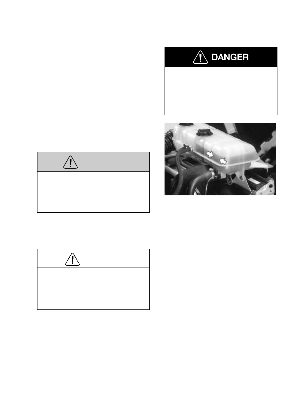
Pre-Trip Inspection and Daily Maintenance 45
Daily Maintenance
The following should be checked daily in
addition to doing the pre-trip inspection of
the truck or tractor and trailer.
While checking the fluid levels, visually inspect hoses, pipes and their connections for
signs of leakage. Inspect the ground under
engine, transmission and rear axle(s) for
signs of leakage.
Check coolant level in the coolant tank.
The level should be above the minimum
mark shown on the side of the tank.
Before working on or inspecting a vehicle, set the parking brakes, place the
transmission in neutral and block the
wheels . Failure to do so can result in
unexpected vehicle movement and can
cause serious personal injury or death.
WARNING
Do not remove the cap to the surge tank
while the engine and radiator are still
hot and under pressure. Scalding fluid
and/or steam may be blown out under
pressure if the cap is taken off too soon.
If the coolant level is low, add more
coolant to the tank so the level is above the
minimum mark. Coolant should be filled
through the cap in the middle of the tank.
CAUTION
To prevent cooling system damage, add
only pre-mixed coolant made up of 50%
clean water and 50% antifreeze. See the
“Operator’s Manual, Maintenance &
Engine” for more detailed information.
W2002049
Page 51

46 Pre-Trip Inspection and Daily Maintenance
WARNING
Keep yourself clear of all moving or hot
engine parts. A hot engine can cause serious burns.
Check oil level in the engine with the dipstick. The oil level should be between the
minimum and maximum marks on the dipstick.
CAUTION
Do not overfill or underfill oil. Premature wear or component damage may
result if you do.
See the “Operator’s Manual, Maintenance
and Engine” for correct types of oil used in
Volvo engines.
CAUTION
If the vehicle is equipped with an aerodynamic bumper, do not step on or press
in between the bumper and the wheel.
Breakage or damage may result.
W2002047
To add oil to the engine, remove oil cap on
the valve cover and fill through the hole.
CAUTION
Make sure the oil added is the same
type of oil that is in the engine. The
wrong type of oil could accelerate wear
on engine if not suited for application.
W2002048
Page 52
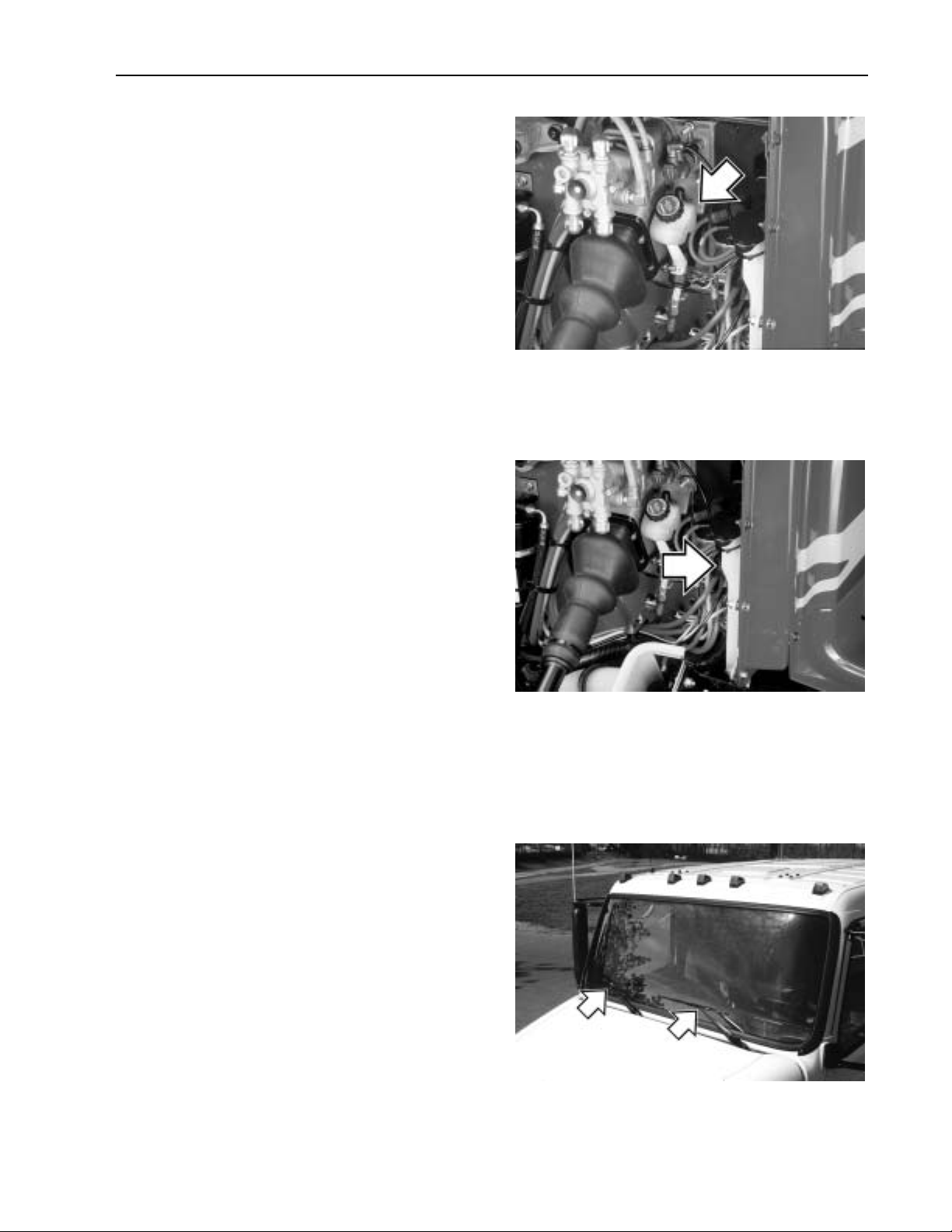
Pre-Trip Inspection and Daily Maintenance 47
Check fluid level in the clutch fluid reservoir. Fluid level should be between the
level marks on the reservoir.
If fluid needs to be added, use brake fluid,
DOT 4.
Check level in the windshield washer reservoir. If washer fluid needs to be added, use
a commercially reputable washer fluid that
has good cleaning capability and does not
freeze in cold weather.
W4000726
Total reservoir capacity is 3.3 gallons
(12.5 liters). An indicator will appear on
the diagnostic display when there is
approximately 1.4 gallons (5.3 liters) remaining in the reservoir.
Check that windshield wipers and washer
are working properly.
The windshield washer spray should cover
the windshield well. The wipers should
clean the windshield in a couple of strokes
and should not leave any streaks.
W8000985
W3000874
Page 53

48 Pre-Trip Inspection and Daily Maintenance
If the windshield needs an overall cleaning,
use a long handled cleaning sponge and
squeegee.
Clean the side windows in the same way
with a long handled sponge and squeegee.
W1000070
Check all lights for proper function:
Headlights
•
Daytime running lights
•
Parking and marker lights
•
Stoplights
•
Turn signals
•
NOTE! Make sure that all fluid levels are
at their proper levels. If the fluids are not at
their proper levels, add as necessary. Refer
to the Engine and Maintenance Manual for
information on what types of fluids are recommended for your Volvo vehicle.
W3000953
Page 54
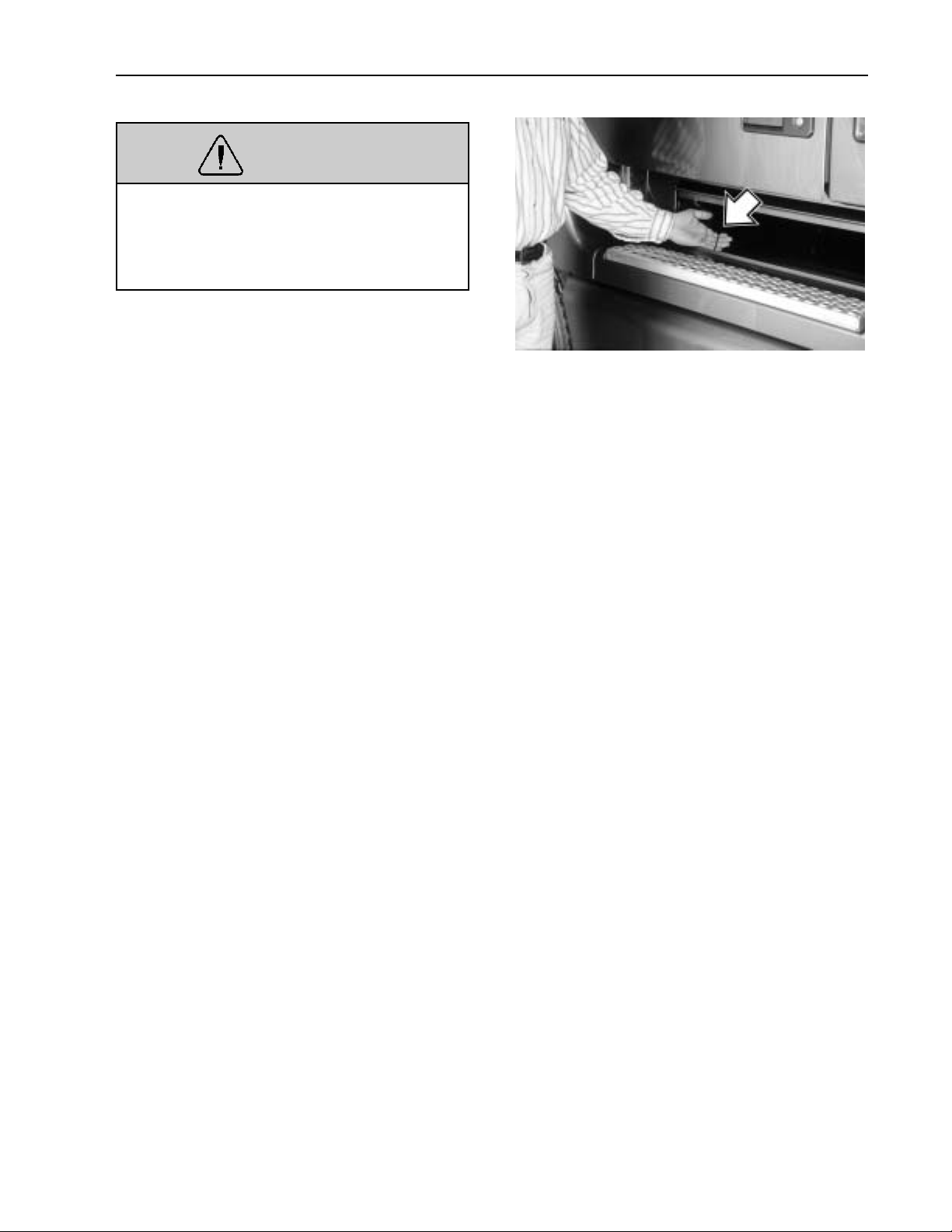
Pre-Trip Inspection and Daily Maintenance 49
WARNING
When draining the air tanks, do not look
into the area of the draining air. Dirt or
sludge particles may be in the air stream
that could cause eye injury.
Empty out the air tanks daily. With the air
system fully charged and with the engine
shut off, listen for air leaks.
W5000601
Page 55
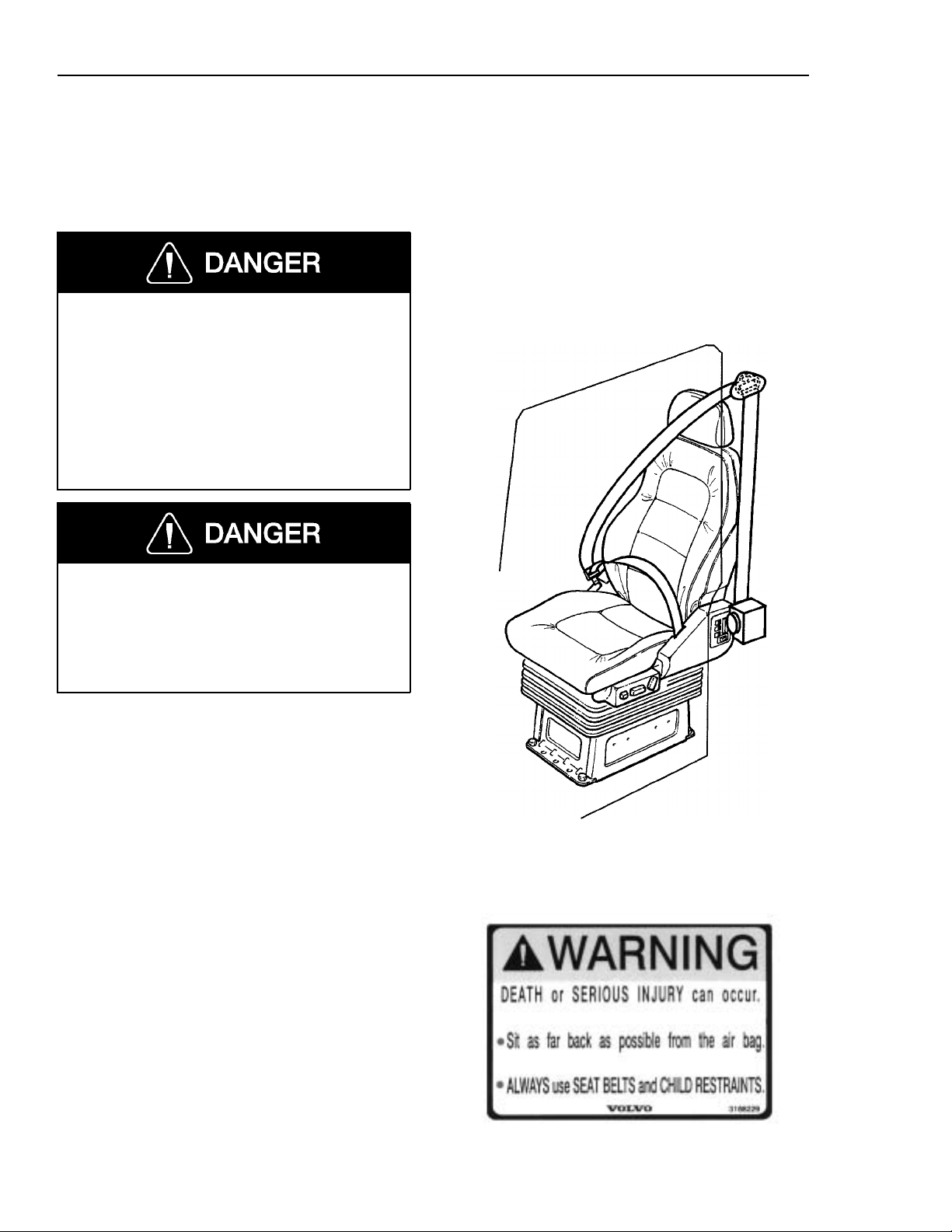
50 Additional Safety Features
Safety Belts
General
Safety belts must be properly worn at all
times by the driver and all passengers
while the vehicle is in motion even if
the vehicle is equipped with a Supplemental Restraint System (SRS or air
bag). Failure to do so can result in serious personal injury or death in the event
of a sudden stop or collision.
Fasten the safety belt before starting to
drive. Trying to fasten the safety belt
while the vehicle is moving may lead to
an accident, causing serious personal injury or death.
Safety belt assemblies installed in this vehicle meet FMVSS 209, “Type 1” and “Type
2” requirements. They are recommended
for all persons weighing over 50 lb (25 kg).
A child restraint system should also be provided for each child weighing 50 lb (25 kg)
or less. It should meet the requirements of
FMVSS 213, “Child Restraint System.”
Carefully read and follow all manufacturer’s instructions on installation and use.
Make certain the child remains in the restraint system at all times while the vehicle
is in motion.
W8001834
W8002741
Page 56
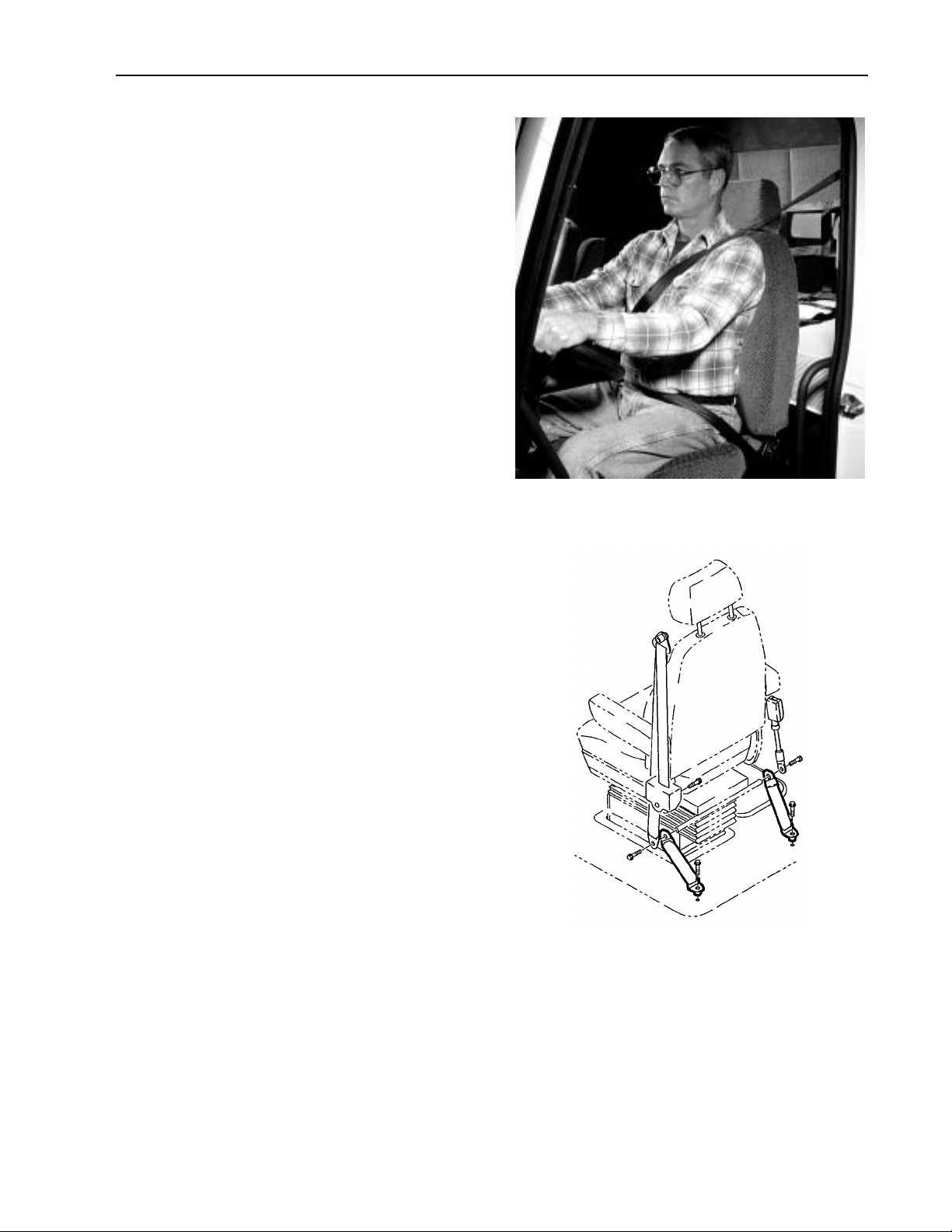
Additional Safety Features 51
Safety belts must be worn by the driver and
all passengers at all times. Before adjusting
or fastening the safety belt, move the seat
forward or rearward and adjust the seat
height as necessary. Sit erect and adjust the
seat cushion and seat back for a comfortable driving position. In the event of a
collision, a correct driving position maximizes the effectiveness of the safety belt.
There are both Federal and State laws governing the use of safety belts. As laws
differ from state to state, make yourself familiar with the current rules.
W8001077
Tether straps are installed on all
suspension-type seats. Tether straps help secure the seat to the floor and are intended
to restrain the seat and safety belt in case
of an accident or sudden stop.
The tethers are not adjustable and do not
need any adjustment.
W8001387
Page 57

52 Additional Safety Features
Operating the Safety Belt
To fasten the safety belt, pull the belt out
from the retractor and insert the latch into
the buckle. Verify proper lock of the latch
by pulling on the latch.
Adjust the slack by pulling on the top part
of the belt until the lower part, or the part
that crosses the lap, is snugly adjusted. Release the top part and let the retractor pull
the belt in.
The lap portion of the safety belt should be
worn low across the pelvic region (hip
bone) and adjusted snugly. Never adjust the
lap belt across the abdomen. A push button
on the buckle is used to release the safety
belt latch by pushing in the button release
on the buckle.
W8001835
The buckle portion of the safety belt system is different depending on the seat
option chosen. The National standard and
comfort seat has a separate buckle that is
attached to a floor anchor by a seat strap.
This seat strap is not adjustable, and does
not need to be adjusted.
The buckle for the seat is bolted to the seat
floor.
If a comfort clip is used on the safety belt,
always adjust the latch so that there is a
maximum of 1 in. (25 mm) slack between
the belt and chest (about the width of two
fingers). If a larger slack is allowed, the effectiveness of the safety belt is decreased in
the event of a collision. Operation of the
clip is described on page 60.
W8001836
Make sure the safety belt is completely retracted and out of the way when not in use.
W8001837
Page 58

Sleeper Safety Restraint
Always use the safety restraint when the
vehicle is in motion. Failure to do so not
only may cause severe injuries or death
to the passenger in the event of an accident but also poses a danger of injuries
to other occupants of the vehicle.
Anytime the vehicle is in motion, a passenger using the sleeper bunk should be
strapped in using the safety restraint.
The top bunk should always be used
with the harness in place, whether the
vehicle is in motion or not. Falling from
the upper bunk can result in severe personal injury or death.
Additional Safety Features 53
W8000895
The restraint netting can be used for securing loose articles. Any loose articles that
can shift in the cab during hard cornering
or braking should be kept restrained.
Fasten the restraint by connecting the
buckle with the latch. Make sure the belts
are not twisted. Test the latch connection
by pulling on the belt. If they come apart,
reconnect and test again. If the connection
can not be made, replace the belt before using the bunk for sleeping during driving.
To loosen the restraint, press the red release
button on the latch (1). Restraints should be
properly stored when not used. Having the
restraint laying loose in the cab can be a
source for unintentional snagging.
W8002475
Page 59

54 Additional Safety Features
Safety Restraint — VN-420, VN–610 and VN–660
The restraint has latches in one end and
buckles in the other so it can only be installed one way. Connect the restraint to the
back wall and the buckles on the floor. Connect the side tethers and adjust the straps to
form a “tent” over the bunk (VN-660 upper
bunk does not have the “tenting” feature).
Safety Restraint — VN-770
Connect the restraint to the back wall first.
The wall connectors are located in the storage units. Connect the lower part of the
restraint to the lower buckles. Connect the
side tethers and adjust the straps to form a
“tent” over the bunk.
NOTE! The restraints for top and bottom
bunks are different. Each belt can only be
installed to the correct bunk.
W8002039
Page 60

Inspection
Failure to properly inspect and maintain
the safety belts can cause serious personal injury or death.
It is critical that any time a vehicle has
been involved in an accident, the entire
safety belt system must be replaced in
the vehicle (which also includes the
sleeper bunk restraints) if they were in
use at the time of the accident. Failure
to replace the safety belt system may result in serious injury or death.
Additional Safety Features 55
Check the belts, buckles, latch plates, retractors, anchorages, and guide loops to
ensure that they are working properly. Look
for loose/damaged parts (without disassembling) that could keep the restraint system
from working properly. If the safety belt,
retractor and hardware were in use during a
collision, they must be replaced. The restraint system anchorage fasteners must be
replaced if necessary. If there is any doubt
about the restraint system’s effectiveness,
replace the entire safety belt assembly.
A damaged safety belt, whether visibly
damaged or not, could result in serious
personal injury in the event of an accident. The safety belt systems should be
replaced at least every five years.
Do not bleach or re-dye the color webbing because it may cause a severe loss
of belt strength. This loss of strength
could allow the safety belt to break
under stress, thus resulting in severe personal injury or death.
Page 61

56 Additional Safety Features
The following maintenance guidelines detail how to inspect safety belts and tethers
for cuts, fraying, extreme or unusual wear
of the webbing, etc., and damage to the
buckle, retractor, hardware or other factors
which indicate that safety belt system replacement is necessary.
Check the web wear at the buckle/latch
area. The webbing must be closely examined to determine if there are any cuts,
fraying or extreme wear in the webbing.
Cuts, fraying or excessive wear would indicate the need for replacement of the safety
belt system.
The D-loop web guide is an area where almost constant movement of the safety belt
webbing occurs because of the relative
movement between the seat and the cab.
This constant movement forms an area
where wear will often occur. The webbing
must be closely examined to determine if
there are any cuts, fraying or extreme wear
in the webbing. Cuts, fraying or excessive
wear would indicate the need for replacement of the safety belt system.
W8001406
W8002478
Page 62

Additional Safety Features 57
Check to make sure that the D-loop web
guide is rotating properly. If the guide is
not rotating properly, the webbing will pull
at the wrong angle through the guide, accelerating wear.
If equipped, check the comfort clip for
cracks or possible damage. Make sure that
it works properly.
W8002477
Check the buckle by inserting the latch and
verifying proper operation. Determine if the
latch plate is worn or deformed. Check the
buckle and latch casing for cracks or
breakage.
W8001404
Page 63

58 Additional Safety Features
The retractor web storage device is
mounted on the B-pillar, just behind the
door in the cab. The retractor is the heart of
the safety belt system and can be damaged
if abused, even unintentionally. Check the
retractor web storage device operation to
ensure that it is not locked and that it spools
out and retracts the webbing properly.
If tethers are being used to anchor the
safety belts to the floor, make sure that they
are properly attached to the seat. Tethers
must also be inspected for web wear and
proper tightness of mounting hardware.
W8002481
All hardware for safety belt mounting
points should be evaluated for corrosion.
All attachment points of the system should
be checked for tightness of mounting
hardware.
Check the web in areas exposed to ultraviolet rays from the sun or extreme dust or
dirt. If the original color of the web in
these areas is extremely faded, the physical
strength of this web may have deteriorated.
If this condition exists, replace the safety
belt system.
W8001387
Page 64

Additional Safety Features 59
Important Facts About Safety Belts in Heavy Trucks
The high mileage associated with heavy
trucks, the continual relative movement of
the seat with the cab, the possible contact
with the vehicle seat or other parts of the
cab structure, and the potential exposure of
this safety belt to severe environmental conditions make it crucial to inspect the seat
belt system regularly. It is recommended
that the system be inspected every 15,000
miles (24,000 km) or more often if the vehicle is exposed to severe environmental or
vocational conditions. Any safety belt system that shows cuts, fraying, extreme or
unusual wear, significant discolorations due
to ultra-violet ray exposure, dusty-dirty
conditions, abrasion to the safety belt webbing or damage to the buckle, latch plate,
retractor, hardware or any other obvious
problem should be replaced immediately,
regardless of the mileage.
Once replacement of the safety belt has
been determined necessary, be certain that
it is replaced only with a Volvo original replacement safety belt. See your authorized
Volvo Truck dealer for replacement. Your
Volvo safety belt system has been developed and tested specifically for heavy
trucks. Replace it only with the exact same
design that the vehicle was equipped with.
If the inspection indicates that any other
part of the safety belt system requires replacement, the entire belt system must be
replaced. An installation guide is attached
to every replacement system, entitled
“Three-Point Safety Belt Installation
Guide.” There are separate safety belt
instruction guides for suspension and stationary seats. Use the proper guide for your
type of seat and follow the instructions
very closely. It is vitally important that all
components are mounted back in the same
positions as the original components that
were removed. This will maintain the design integrity of the mounting points for the
safety belt assembly.
Page 65

60 Additional Safety Features
Comfort Clip Operation
When provided, the comfort clip is located
on the shoulder strap just below the D-ring.
When adjusting the comfort clip, the following procedure must be followed for
proper adjustment:
1 Pull out only enough webbing to allow
slight pressure to the shoulder and
chest. Allow no more than a 1 in.
(25 mm) slack when measured between the chest and the belt.
2 To activate the clip mechanism feature,
lift the lever up to clamp the webbing
in place.
NOTE! When the safety belt is not in use,
the clip should be in the open position to
allow the seat belt to retract to its proper
position. Also make sure that the adjustment of the comfort clip does not interfere
with the operation of the safety belt.
Always adjust the clip so that there is a
maximum of 1 in. (25 mm) of slack between the belt and chest (about two fingers
width). If a larger slack is allowed, the effectiveness of the safety belt is decreased in
the event of a collision.
W8002388
Open position
W8001837
Page 66

Additional Safety Features 61
SRS Airbag
WARNING
The SRS airbag is intended to supplement — not replace — the standard
safety belt. The airbag is not deployed
when the truck is hit from behind, from
the side or if it rolls over. For best protection, sit in a normal, upright position.
Always wear the safety belt.
For added safety, the vehicle may be
equipped with an airbag or SRS (Supplemental Restraint System) as a supplement
to the standard three-point anchored safety
belt. The SRS is designed to reduce the risk
of injury to the driver’s face and upper part
of the body. Together with the safety belt,
the airbag helps prevent the driver from being thrown against the steering wheel,
windshield or other hard surfaces in the cab.
The Volvo SRS Airbag provides increased
protection in frontal collisions, where the
vehicle collides with a fixed or heavy object
with enough force to activate the sensors
which then activates the airbag. Damage to
the vehicle is not always proportional to
whether the SRS Airbag deploys or not.
The SRS Airbag is not designed to be activated with:
Collision from the sides
•
Collision from the rear
•
Rolling over
•
Head-on collisions at low speed or
•
against soft objects such as bushes,
snow drifts, etc.
Page 67
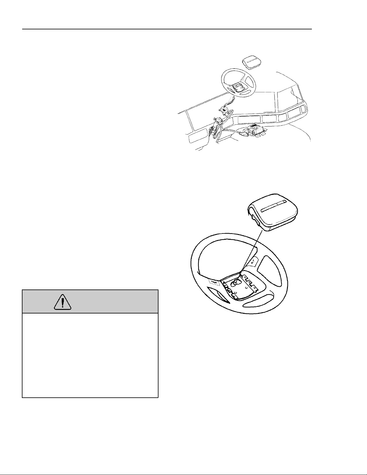
62 Additional Safety Features
SRS System
The inflatable airbag is folded into the center of the steering wheel. It inflates in the
event of a serious collision above a certain
level, where the angle of impact, crash
severity, speed and nature of the object involved in the collision all play a part in
whether or not the airbag is activated.
T8006849
The system consists of a gas generator surrounded by the inflatable airbag. In the
event of a sufficiently violent collision, a
control unit activates the gas generator ignitor and the airbag inflates. To cushion the
impact, the airbag deflates when compressed. This also releases some non-toxic
smoke into the cab. The entire sequence,
from inflation to deflation of the airbag,
takes a few tenths of a second.
WARNING
Never attempt to drive with a deployed
airbag. With the bag hanging out of the
hub of the steering wheel, the truck may
be more difficult to steer. In addition,
other safety systems may be damaged.
Continuous exposure to the smoke and
dust created during the deployment of
the airbag can cause irritation to the skin
and eyes.
T8006855
Page 68
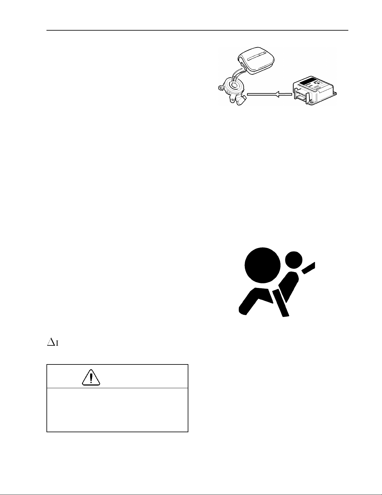
Additional Safety Features 63
The SRS system is continually monitored
by the control unit. A control unit is
mounted on a bracket above the engine
cover which detects deceleration. The control unit also contains a standby power unit
which can supply the system with power
for a short time, should the normal supply
be broken.
If the control unit detects a sufficiently violent deceleration (collision), the system is
activated. The gas generator triggers and
fills the bag with a non-toxic gas within a
few hundredths of a second. During a collision, after the bag has been filled, gas flows
out through two holes in the weave. These
holes are large enough to let the airbag collapse slowly, gently catching the driver.
T8006857
In the event of a problem in the SRS system, a telltale shows on the graphic display
in the instrument cluster. This telltale, together with other telltales in the cluster,
also light up when the engine is started.
The telltale should go out after approximately 10 seconds when the starting key
has been turned to the drive position.
If a problem develops in the system, the
1
INFO telltale will come on together with
the SRS telltale.
CAUTION
The vehicle should be taken to an authorized Volvo Truck dealer immediately if
the SRS telltale stays on or lights up
when the vehicle is being driven.
W3000982
Page 69

64 Additional Safety Features
Warning Labels
The label attached to the left hand sunvisor
shows the year and month when a Volvo
Truck dealer should be contacted for a
specific inspection and for a possible replacement of the airbag. This is done to
guarantee the function of the airbag after
the stated date. Replace the label when replacing the airbag module. Never attempt
to make any adjustments to SRS components yourself.
Steering shafts and steering wheel should
not be removed, adjusted or replaced without following the proper work procedure.
Failure to do so can damage the SRS system to the point where it does not work any
longer. A warning label is located on the
upper steering shaft.
T8006843
T8006842
There is also a label on the inside of the
windshield that indicates the inclusion of
an airbag to the vehicle safety features.
When equipped with an airbag, a label
about the correct procedure for protecting
small children and protecting the driver is
attached to the left hand, overhead storage
lid or back of sunvisor.
T8006841
W8002741
Page 70

Additional Safety Features 65
Any queries concerning the SRS system
should be directed to a Volvo Truck dealer.
There is no maintenance required for the
SRS system until the date stated on the
warning label located on the left hand sunvisor.
Never attempt to repair any part of the
SRS system. Any interference with the
system may cause it to malfunction and
result in serious injury or death. Work
on the system may only be carried out
by an authorized Volvo Truck dealer.
To allow the SRS system to work as designed:
Never drive an SRS system equipped
•
vehicle with the hands on the steering
wheel pad/airbag module.
No objects, accessory equipment or
•
stickers may be placed on, attached to
or installed near the SRS cover in the
center of the steering wheel.
Page 71

66 Additional Safety Features
General Information
When is the airbag deployed?
The airbag is only deployed during a headon collision, where the vehicle hits a fixed
or heavy object with sufficient force. The
SRS system registers both the force of the
collision and the internal forces caused by
the collision. The control unit determines if
the collision is sufficiently violent for the
airbag to be deployed.
NOTE! The SRS system is only activated
once in a collision. If the airbag has deployed, the following is recommended:
Have the vehicle towed to a Volvo
•
Truck dealer. Even if the vehicle can
be driven after a collision, it is not
recommended to drive the truck
with the airbag deployed.
Have an authorized Volvo Truck dealer
•
change the components in the SRS
system.
Only use original Volvo parts when re-
•
placing the SRS system components
(airbag, safety belt, etc.).
When is the airbag not deployed?
Not all frontal collisions activate the SRS
system. In a collision with a soft object (a
snow drift or bush for example, or a hard
or fixed object at low speed), there is no
need for the SRS system to be activated.
The airbag is usually not inflated in response to side-on collisions, impacts from
the rear or if the vehicle overturns. The extent of damage to the vehicle is no measure
of how well the SRS system works.
Page 72

Additional Safety Features 67
Can the airbag be deployed accidentally?
The complete SRS system is constructed so
that the airbag only inflates in particular
collision conditions. The SRS system has
its own diagnostic unit which continuously
monitors the functioning of the system.
Make a habit of checking the SRS system
telltale light when starting and driving the
vehicle.
Heart of the Volvo safety system
The three-point anchored safety belt is
the heart of the Volvo safety system. The
belt should be worn at all times. The SRS
system is intended as a supplement to the
three-point anchored safety belt.
Page 73
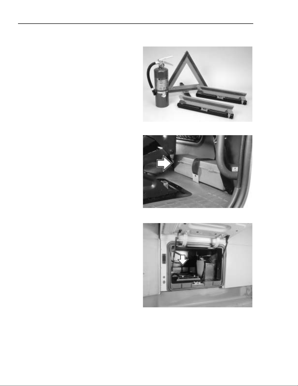
68 Additional Safety Features
Safety Equipment
Safety triangles and fire extinguishers are
available as optional equipment. The fire
extinguisher should be located by the base
of the driver seat, between the seat and the
door. Depending on the cab style, the
safety triangles are located in different
places in the cab.
Day Cab
The warning triangles are stored in a box
that is strapped to the back wall.
W1000071
Sleeper Cab
The warning triangles are stored in a box
that is strapped to the inner wall of the
right side luggage compartment.
W0001372
W1000139
Page 74

Additional Safety Features 69
VORAD Collision Warning System
The Eaton VORAD computerized Collision
Warning System constantly monitor vehicles ahead with a front end mounted radar
and in a blind spot area with an optional
side mounted radar. The Collision Warning
System warns the driver of potentially dangerous situations by activating visual and
audible alerts.
The Eaton VORAD Collision Warning
System is intended solely as an aid for
an alert and conscientious professional
driver. It is not to be used or relied upon
to operate the vehicle. Use this system
together with rear view mirrors and
other instrumentation to maintain safe
operation of the vehicle. Operate a VORAD equipped vehicle in the same safe
manner as if VORAD was not installed.
The Eaton VORAD Collision Warning
System is not a substitute for safe driving procedures nor will it compensate
for any driver impairment, such as
drugs, alcohol or fatigue.
The Eaton VORAD Collision Warning
System may provide little or no warning
for some hazards like: alerts for pedestrians, animals, oncoming vehicles and
cross traffic. SmartCruise will not react
to stationary objects and it does not have
the capability to stop the vehicle.
Failure to follow these instructions may
lead to a crash resulting in severe personal injury or death.
If your vehicle is equipped with the Eaton
VORAD Collision Warning System, read
the manufacturer’s Driver Reference Manual before taking the vehicle on the road.
Page 75

70 Instruments and Controls
Dash Overview
1 Air Vents ( page 182)
2 Diagnostic Test Connection
3 Left Switch Cluster ( page 99)
4 Headlight Switch ( page 104)
5 Driving/Fog Lights - option ( page 105)
6 Instrument Light Dimmer ( page 113)
7 Climate Unit Control Panel ( page 174)
8 Hood Latch Handle ( page 30)
9 Pneumatic Switches ( page 110)
10 Cigar Lighter ( page 113)
Operating
Before driving this vehicle, locate the instruments and controls, and become
thoroughly familiar with their operation.
After starting and when driving, always
check that the instrument readings are
normal.
W8002383
11 Ashtray
12 Instrument Cluster, Left ( page 74)
13 Instrument Cluster, Main ( page 82)
14 Instrument Cluster, Right ( page 89)
15 Trailer Hand Brake Control ( page 283)
16 Tractor Parking Brake ( page 278)
17 Trailer Air Supply ( page 278)
18 Radio - option ( page 233)
19 Optional Switches ( page 112)
20 Right Switch Cluster ( page 106)
NOTE! Availability of gauges depends on
chosen options. All gauges and telltales
may not be used in all vehicles.
Page 76

Instruments and Controls 71
Instrument Cluster Overview
W3004396
General
The cluster is available in seven different
configurations, with the speedometer either
graded in mph or km/h. The cluster consists of three combined sections:
Left Section
The left section can include pyrometer, engine oil pressure gauge, engine coolant
temperature gauge, turbo boost pressure
gauge and a graphic display for driver
information. See page 74 for gauge information and page 114 for graphic display
information. There are telltales in the lower
part. Please refer to page 77 for telltale
information.
Center Section
The center section contains tachometer,
speedometer and odometer. See page 82 for
gauge information. In the lower part there
is a central warning lamp and telltales for
different vehicle functions. Please refer to
page 85 for telltale information.
Right Section
The right section can include forward and
rear axle temperature gauges, fuel level
gauge, application air pressure gauge, front
and rear brake air pressure gauges. Vehicles
with rear air suspension may have an air
suspension pressure gauge. See page 89 for
gauge information. There are telltales in the
lower part. Please refer to page 92 for telltale information.
Page 77

72 Instruments and Controls
Telltale Overview
1 Engine Preheat ( page 78)
1
2 Yellow
( page 79)
3 Red
( page 80)
4 No Charge ( page 81)
5 Left Turn ( page 86)
6 Fifth Wheel Lock ( page 86)
7 Wheel Differential Lock
( page 86)
8 Axle Differential Lock
( page 86)
9 High Beam ( page 87)
10 Safety Belt ( page 87)
11 Parking Brakes ( page 87)
12 Tractor ABS ( page 88)
INFO Light
1
STOP Light
W3004406
13 Trailer ABS ( page 88)
14 Air Suspension Level
( page 88)
15 Mirror Heater ( page 88)
16 Right Turn ( page 86)
17 Transmission Temperature
( page 92)
18 Check Transmission
( page 92)
19 Traction Control System
( page 92)
20 Wait to Start (Not used)
21 Transmission in Neutral
( page 92)
22 Water in Fuel (Not used)
Page 78

Instruments and Controls 73
Graphic Display Telltale Overview
1 Voltmeter ( page 162)
2 Engine oil temperature ( page 159)
3 Transmission oil temperature
( page 125)
4 Preheating active ( page 78)
5 Acknowledged warning ( page 130)
6 Alarm clock on ( page 167)
7 PTO engaged ( page 101)
8 Cruise control engaged ( page 265)
9 Airbag (SRS) ( page 63)
W3003534
10 Coolant level ( page 126)
11 Washer fluid level ( page 120)
12 Engine airfilter clogged ( page 121)
13 Too cold for engine brake ( page 289)
14 Overheating, instrument cluster
( page 120)
15 Engine preheat fault ( page 249)
16 Engine oil pressure ( page 76)
17 Coolant temperature ( page 75)
Page 79

74 Instruments and Controls
Left Instrument Section
A Pyrometer (option) (this page)
B Engine Coolant Temperature
( page 75)
C Engine Oil Pressure ( page 76)
D Turbo Boost Pressure (option)
( page 77)
E Graphic Display ( page 114)
F Telltale Indicators ( page 77)
A — Pyrometer (option)
An engine pyrometer system indicates the
exhaust temperature, which helps the operator get the best efficiency from the engine.
Variations in engine load can cause the exhaust temperature to vary. For example,
high exhaust gas temperature is the result
of prolonged engine lugging or overfueling.
If the pyrometer reading shows that exhaust
temperature exceeds normal, reduce fuel to
the engine until exhaust temperature is reduced. Shift to a lower gear if the engine is
overloaded.
W3003644
W3003632
Page 80
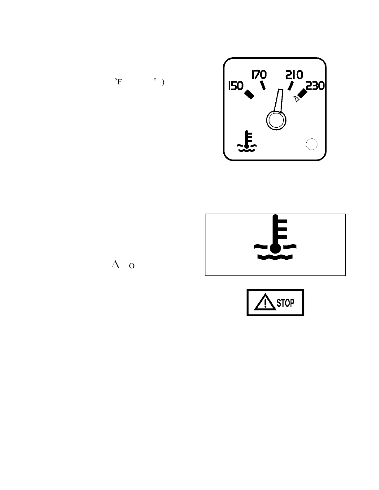
Instruments and Controls 75
B — Engine Coolant Temperature
The gauge indicates engine coolant temperature. Normal operating temperature
reading is 165 to 205
the VOLVO engine. The temperature, under
normal driving conditions, must be below
the red sector. The temperature range for
the coolant will vary depending on the type
of engine, load, grade, ambient air temperature and operating conditions. If the
temperature remains below or exceeds the
normal temperature range, the cooling system should be checked for problems by
your Volvo Truck dealer.
F (75 to 95C) for
W3003769
The LED light in the lower right corner of
the gauge lights up solid when coolant temperature is excessive. The temperature limit
is dependent on the engine manufacturer
electronic program. Together with the
1
gauge light, the red
STOP telltale will
come on and the buzzer will also sound.
The engine is at risk and the engine controller may react by derating the engine
power. Stop at the first safe place where the
problem can be checked.
NOTE! If the coolant temperature returns
to normal shortly after exceeding the limit
and no repair has been made, the warning
messages go out but there will be a fault
message logged.
W3003614
T3008861
Page 81

76 Instruments and Controls
C — Engine Oil Pressure
The gauge indicates oil pressure by a sensor
directly connected to the engine lubrication
system. Normal oil pressure is 30 to 70 psi
(210 to 480 kPa) when the engine is at normal operating temperature. At idle speed,
the pressure may drop to 5 to 20 psi (35 to
140 kPa). When first starting a cold engine,
oil pressure may exceed 90 psi (620 kPa).
The LED light in the lower right corner of
the gauge lights up solid when the oil pressure is too low. The pressure limit is
dependent on the engine manufacturer electronic program. When the gauge light
1
comes on, the red
blinking, the buzzer sounds and the oil
pressure symbol appears on the graphic display. The engine is at risk and the engine
controller may react by derating the engine
power, for example. Bring the vehicle to a
safe stop where the problem can be
checked.
STOP telltale starts
W3003768
W3003613
1
With very low oil pressure, the red
telltale lights up solid. The engine will shut
down within 30 seconds from when the
light came on. Pull off the road as soon as
possible without being a safety hazard.
Failure to take necessary action when
1
the
result in automatic engine shutdown and
loss of power steering assist. Vehicle
crash resulting in personal injury or
death can occur.
STOP telltale is on, can ultimately
STOP
T3008861
Page 82

Instruments and Controls 77
D — Turbo Boost Pressure (option)
The gauge indicates intake manifold pressure on the engine. The pressure is
generated by the turbo. Boost pressure
should be the same at a given engine temperature, speed and load. Turbo boost
pressure will vary for different engines and
vehicle models. By monitoring the gauge,
the operator can avoid engine problems.
W3003631
F — Telltale Indicators, Left Section
1 Engine preheat telltale ( page 78)
2 Caution telltale ( page 79)
3 Stop telltale ( page 80)
4 No Charge telltale ( page 81)
W3003645
Page 83

78 Instruments and Controls
1 — Engine Preheat Telltale
The amber telltale will light up when the
intake manifold preheater is operating. The
heater is used for better cold starts. Operation time of the heater can vary in several
steps from 0 to 50 seconds depending on
coolant temperature and outside air temperature. On cold mornings, the preheater will
be on for the maximum 50 seconds. When
the ignition key has been turned to the preheat position, the preheater coils in the
intake manifold are activated to warm the
intake air. Once the engine is started, the
preheater may be re-engaged to assist in a
quicker engine warm-up. See page 249 for
information on using the preheater.
T3008841
Page 84
Instruments and Controls 79
2—1INFO Telltale
The yellow1INFO telltale lights up to indicate a control system or component
malfunction. In some cases, the engine
power may be derated (see page 120).
When the telltale comes on, stop at the first
safe place where the problem can be
checked.
When ignition is switched on, the telltale
goes out unless a defect is detected.
NOTE! On vehicles equipped with a Volvo
engine, the telltale is on for 3 to 5 seconds
after the ignition key switch is turned on.
T3008860
See page 119 for a listing on related messages that trigger this telltale.
Page 85

80 Instruments and Controls
3—1STOP Telltale
Failure to take necessary action when
1
the
result in automatic engine shutdown and
loss of power steering assist. Vehicle
crash resulting in personal injury or
death can occur.
The
the operator that a severe problem has been
detected and in some cases a preventive action may be taken by the engine electronics
to protect the engine. For example: if oil
pressure or coolant level drops too low, the
engine will be forced to low idle and when
the vehicle speed is zero, the engine shuts
down. Another example is: with excessive
coolant temperature, the engine will gradually reduce power output to 50%. This
telltale always activates the buzzer.
STOP telltale is on, can ultimately
1
STOP telltale lights up red to alert
T3008861
The engine may be started again after the
key is turned off and then back on. However, it will only operate for 30 seconds
unless the problem is resolved.
CAUTION
If the problem is allowed to persist, serious damage to the engine may occur.
Always repair the cause of the problem
before taking the vehicle into service
again.
The engine could be forced to low idle
within 30 seconds from when the light
came on. Pull off the road as soon as possible without being a safety hazard.
See page 126 for a listing on related messages that trigger this telltale.
Page 86

Instruments and Controls 81
4 — No Charge Telltale
The No Charge telltale lights up red when
a problem exists in the charging system or
when there is no output from the alternator,
such as when the engine is not running.
The No Charge telltale lights up dimly
when there are several volts difference between the system voltage and the alternator
output voltage. The telltale shines brighter
as the alternator output voltage drops.
For more information on the electrical system, see page 293.
T3008832
Page 87

82 Instruments and Controls
Main Instrument Section
G Tachometer ( this page)
H Speedometer ( page 83)
J Master Warning Telltale ( page 84)
K Warning Telltales ( page 85)
G — Tachometer
The tachometer is electrically driven by a
signal from the engine. Monitor the
tachometer to guide correct gear shifting
and to prevent engine overspeeding when
descending steep grades. Each engine has
its ideal operating ranges for power and
economy. Read the engine manufacturer’s
manual to find out the best ranges for each
engine.
W3003643
CAUTION
Always keep an eye on the tachometer
during downhill runs. Do not allow the
engine to over-speed. Excessive engine
over-speed can result in serious engine
damage.
W3003639
Page 88
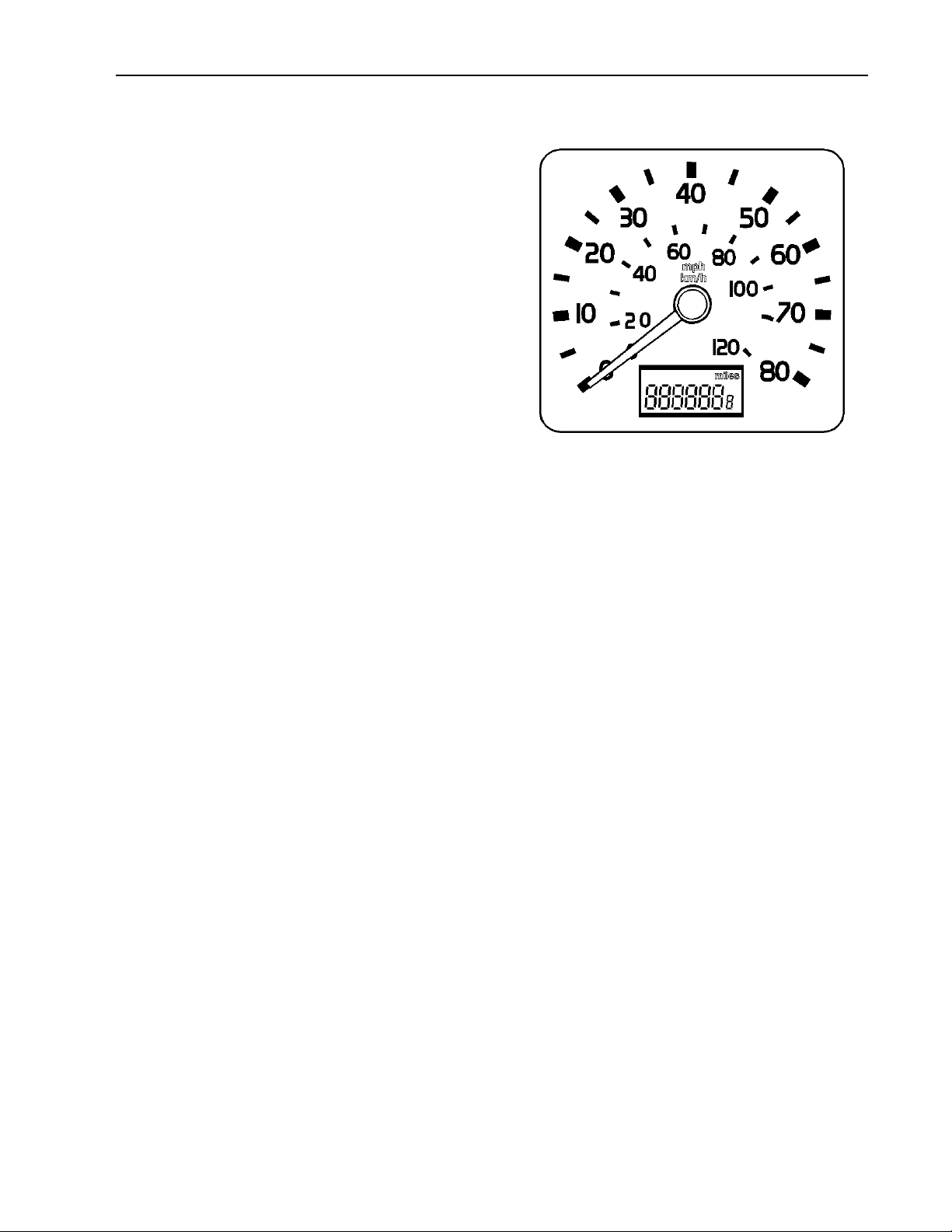
Instruments and Controls 83
H — Speedometer and Odometer
The speedometer is driven by the vehicle’s
electronic system. Recalibration of the
speedometer can be made to compensate
for tire size changes or other changes in the
vehicle driveline. This is done by reprogramming the engine or transmission
electronic controller. Reprogramming can
be performed by your authorized Volvo
Truck dealer.
The odometer is a Liquid Crystal Display
(LCD) mounted in the lower speedometer
face. The odometer registers up to
999,999.9 miles or km. The internal electronics will make distance conversions
between miles and km automatically.
W3003640
To be able to read the current mileage
without turning the ignition on, press any
graphic display control to activate the
odometer and clock for approximately 30
seconds.
Page 89
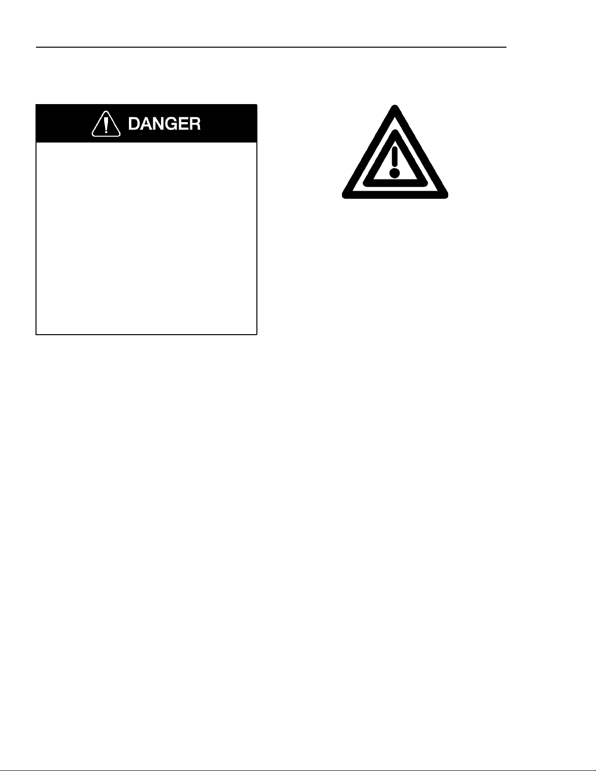
84 Instruments and Controls
J — Master Warning Telltale
The Master Warning Telltale and buzzer
alerts of a dangerous situation. Air pressure is low and the remaining air volume
may not be enough for repeated braking.
The emergency brakes may engage,
causing a wheel lock-up, loss of vehicle
control and become a hazard to following vehicles. Bring the vehicle to a
controled stop. Failure to follow these
precautions can result in loss of braking
control and serious personal injury or
death can occur as a result of a vehicle
accident.
W3000638
This will light up when either front or rear
air brake system pressure drops below 60
psi (410 kPa) or lower. The buzzer will
also sound when the telltale lights up.
When the pressure goes above 60 psi in
both front and rear brake circuits, the telltale will automatically go out.
Air brake system pressure should be between 90 to 135 psi (620 to 930 kPa) for
normal operation. The master warning telltale comes on and the buzzer sounds when
air pressure has dropped to 60 psi or lower.
If the air pressure is allowed to drop below
30 to 40 psi (200 to 275 kPa) in both
systems, the parking spring brakes will automatically engage and stop the vehicle.
When the master warning telltale comes on
and before the parking spring brakes engage, stop the vehicle in a controlled
manner at an off-road location so as not to
be a hazard to other vehicles on the road.
Refer to page 273 for more information
about the brakes.
Page 90

Instruments and Controls 85
K — Warning Telltales, Center Section
1 Left Turn Telltale ( page 86)
2 Fifth Wheel Lock Telltale ( page 86)
3 Wheel Diff. Lock Telltale ( page 86)
8 Anti-Lock Brake System (Tractor or
9 Anti-Lock Brake System (Trailer)
W3003646
Truck) Telltale ( page 88)
Telltale ( page 88)
4 Interaxle Diff. Lock Telltale ( page 86)
5 High Beam Telltale ( page 87)
6 Safety Belt Telltale ( page 87)
7 Parking Brake Telltale ( page 87)
NOTE! All telltales may not be used in all
vehicles.
The telltale strip is located below the
tachometer and speedometer. A yellow caution telltale indicates that there is a system
or component in the vehicle that requires
the operator’s attention. A red warning telltale indicates that there is a system or
component that should be checked before
the vehicle is driven any further.
10 Air Suspension System Telltale
( page 88)
11 Mirror Defroster Telltale ( page 88)
12 Right Turn Telltale ( page 86)
Page 91
86 Instruments and Controls
Left and Right Turn Telltales
This lights up green when the turn signal is
activated and blinks in time with the outside turn signal lamps. An audible signal
also sounds in time with the telltale. A single short beep is heard when the telltale
lights up.
5th Wheel Lock Telltale
This telltale will light up yellow when the
pneumatic switch for the 5th wheel slide
lock is turned on. It will stay lit until the
switch is turned to the off position again.
See the 5th wheel uncoupling section on
page 333 for correct use.
W3000903
Wheel and Interaxle Differential Lock Telltales
These telltales will light up yellow when
the pneumatic switches for either the wheel
or interaxle differential lock are turned on.
For the interaxle lock, the telltale is activated by the switch. For the wheel lock, a
switch in the axle turns the telltale light on
only when the lock is actually engaged. It
turns the light off only when the lock is actually disengaged. See page 311 for proper
differential lock use.
W3000621
W3000904
Page 92

Instruments and Controls 87
High Beam Telltale
Any time the high beams are activated, by
the high/low beam switch or the high beam
flash switch, the telltale lights up blue. For
information on switching high/low beam,
see page 97.
Safety Belt Telltale
The telltale lights up red each time the ignition is turned on to remind the driver to
fasten the safety belt. It stays lit for 10 seconds and then goes out automatically.
Before adjusting the safety belt, make sure
the vehicle is stationary and that the seat
has been adjusted as required. Do not attempt to adjust the safety belt or seat while
the vehicle is in motion. For proper use of
the safety belt, see page 52.
W3001303
W3000625
Parking Brake Telltale
The telltale lights up red when the parking
brake valve knob is pulled out. The daytime running light (DRL) function is also
dependent on the parking brake application.
Any time the parking brake telltale is on,
the DRL is deactivated.
Never exit your vehicle unless the parking brake is set. Failure to do so can
result in unexpected vehicle movement
and cause personal injury or death.
For proper use of the parking brake, see
page 278.
W3000627
Page 93

88 Instruments and Controls
ABS Telltale, Tractor and Trailer
The telltale lights up amber if the AntiLock Brake System (ABS) senses a
problem under the following conditions:
1 The system will go through its self
test when the ignition switch is turned
on and the telltale should continue to
be on. The light should go out when
the vehicle speed reaches over approximately 7 mph (11 km/h). If the
telltale stays on at higher speed, there
is a problem with the ABS.
2 The ABS telltale lights up during driv-
ing. The ABS self test has detected a
fault in the system.
W3000905
The vehicle can still be driven with a problem in the ABS. However, the ABS will not
be operating and standard air braking is in
effect. For more information, see page 285.
The trailer ABS telltale is in effect for vehicles manufactured after February 2001.
Air Suspension Telltale
The telltale lights up amber when the suspension leveling valve is activated. As long
as the switch is activated, the suspension is
lower than normal and the telltale is on. For
proper use of the suspension level control,
see fifth wheel uncoupling on page 329.
W3002596
Mirror Defroster Telltale (option)
The telltale lights up amber when the mirror defrost switch is engaged. Heater
temperature is automatically regulated by
an internal system in the mirror head.
W3000632
Page 94

Instruments and Controls 89
Right Instrument Section
L Forward Drive Axle Oil Temperature
(option) ( this page)
M Rear Drive Axle Oil Temperature
(option) ( this page)
N Fuel Level Gauge ( page 90)
O Application Air Pressure (option)
( page 90)
OR
Air Suspension Pressure (option)
( page 90)
P Front Brake System Air Pressure
( page 91)
Q Rear Brake System Air Pressure
( page 91)
W3004407
R Warning Telltales ( page 92)
L & M — Forward & Rear Drive Axle Oil Temperature (option)
The gauges are connected to temperature
senders installed in the axles. Normal operating temperature range is up to 250
C). If average oil temperature consis-
(120
tently goes above 250
F (120C), more
frequent oil changes are needed or an oil
cooler could be installed.
F
CAUTION
A sudden increase in oil temperature
that is not caused by a load increase
may indicate mechanical failure. Bring
the vehicle to a safe stop where the
problem can be checked. Do not operate
vehicle until correcting the problem.
W3003634
Page 95

90 Instruments and Controls
N — Fuel Level Gauge
The gauge is connected to a sending unit in
the fuel tank. There is only one sender even
if the vehicle is equipped with dual tanks.
O — Application Air Brake Pressure (option)
W3003628
Air gauges are directly connected to the air
brake system. They will indicate the brake
application pressure from either the front,
rear or trailer circuit pressure.
The gauge will not register air pressure until the foot brake pedal is depressed or the
trailer hand brake is applied.
O — Air Suspension Pressure (option)
Air gauges are directly connected to the air
suspension system. It will indicate the suspension pressure in the air springs.
The pressure shown on the gauge is a crude
indication of the load on the rear axle(s).
The gauge should not be used for trying to
balance the load between the axles.
W3004302
W3003633
Page 96
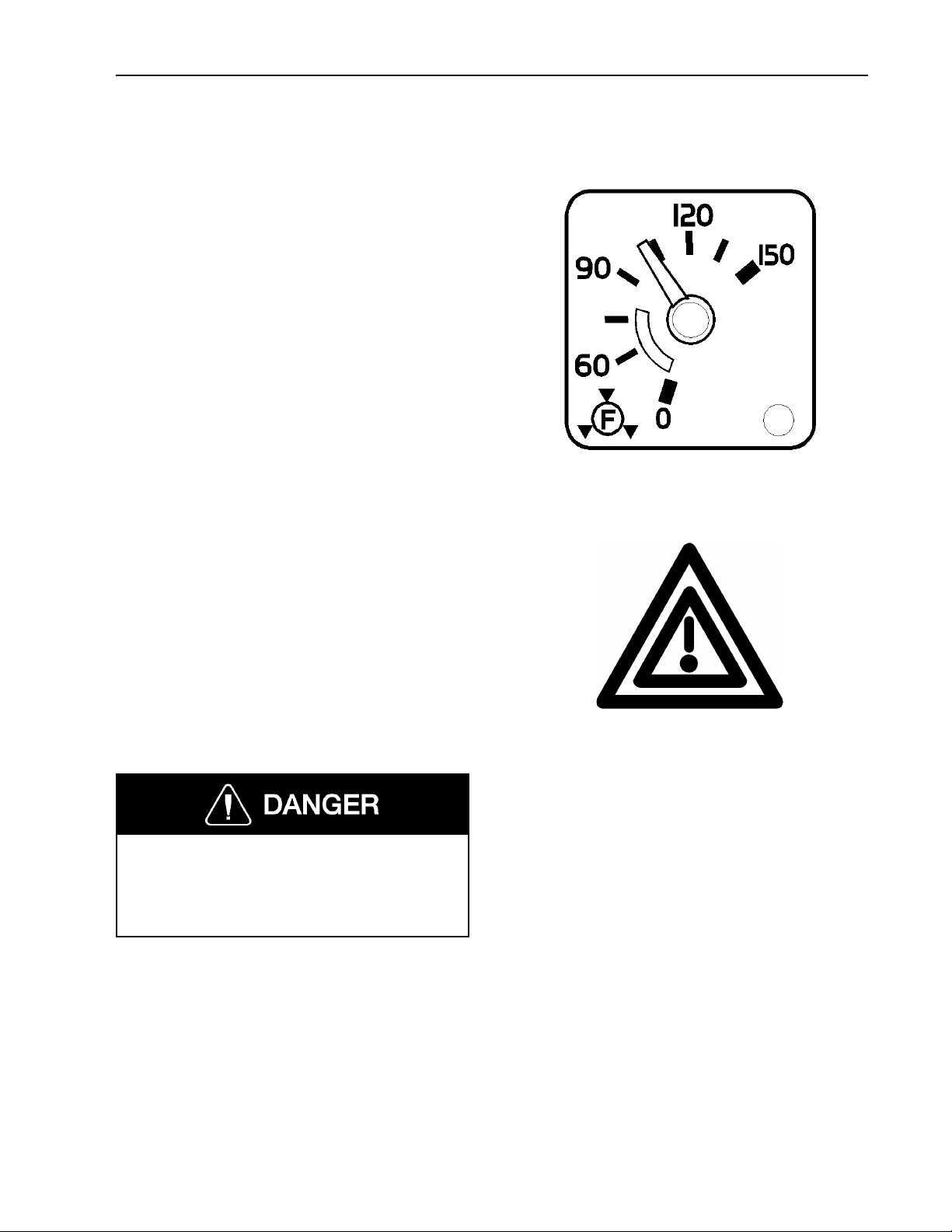
Instruments and Controls 91
P & Q — Front and Rear Brake System Air Pressures
The system air gauges are directly connected to the front and rear circuit tanks.
The two gauges should register equal air
pressure. Air brake system pressure should
be between 90 to 135 psi (620 to 930 kPa)
for normal operation. The pointers in the
two gauges should register equal air pressure. By observing the gauge pointers, the
operator can detect a pressure drop if an air
leak develops and can readily identify the
circuit affected. See page 273 for more information.
There is a low-air warning switch in each
gauge. If the pressure in a brake circuit air
tank drops below approximately 60 psi
(420 kPa), the red indicator in the lower
right corner of the gauge will light up and
the master warning indicator and the buzzer
will simultaneously come on. If the air
pressure is allowed to drop below 30 to 40
psi (205 to 275 kPa) in both systems, the
parking brakes will automatically engage to
stop the vehicle. Refer to page 273 for
more information about the brakes.
Master Warning Indicator
W3000638
W3003637
Failure to observe these precautions can
result in the loss of braking performance
and personal injury or death can occur
as a result of a vehicle crash.
Page 97
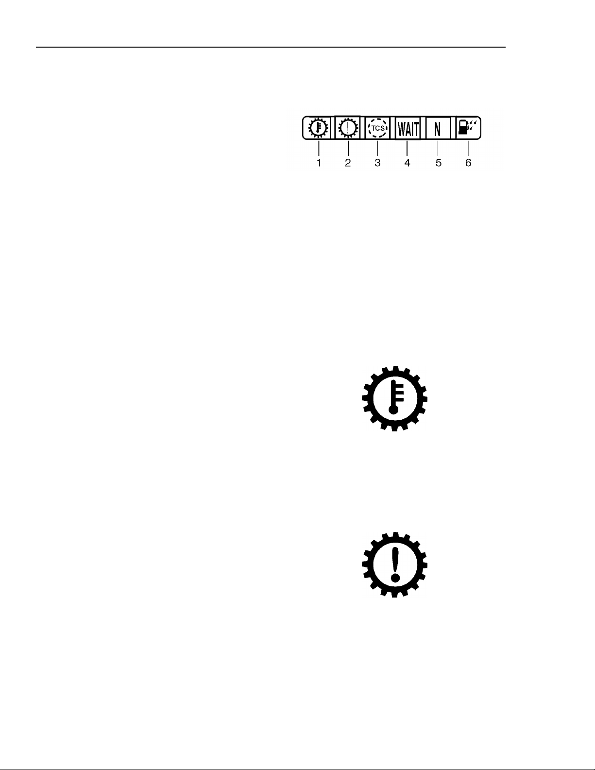
92 Instruments and Controls
R — Warning Telltales, Right Section
1 Transmission Temperature (this page)
2 Check Transmission (this page)
3 Traction Control System ( page 93)
4 Wait to Start (Not used)
5 Automatic Neutral ( page 94)
6 Water in Fuel (Not used)
Transmission Temperature Telltale
The Transmission Temperature Telltale is
for the Allison WTEC III transmission. The
amber warning signal lights up and a
buzzer sounds when the transmission temperature is too high.
W3004416
W3004305
Check Transmission Telltale
The Check Transmission Telltale is for the
Allison WTEC III transmission. The red
warning signal lights up to indicate a transmission problem. Depending on the severity
of the problem, shifts may be restricted.
W3004306
Page 98
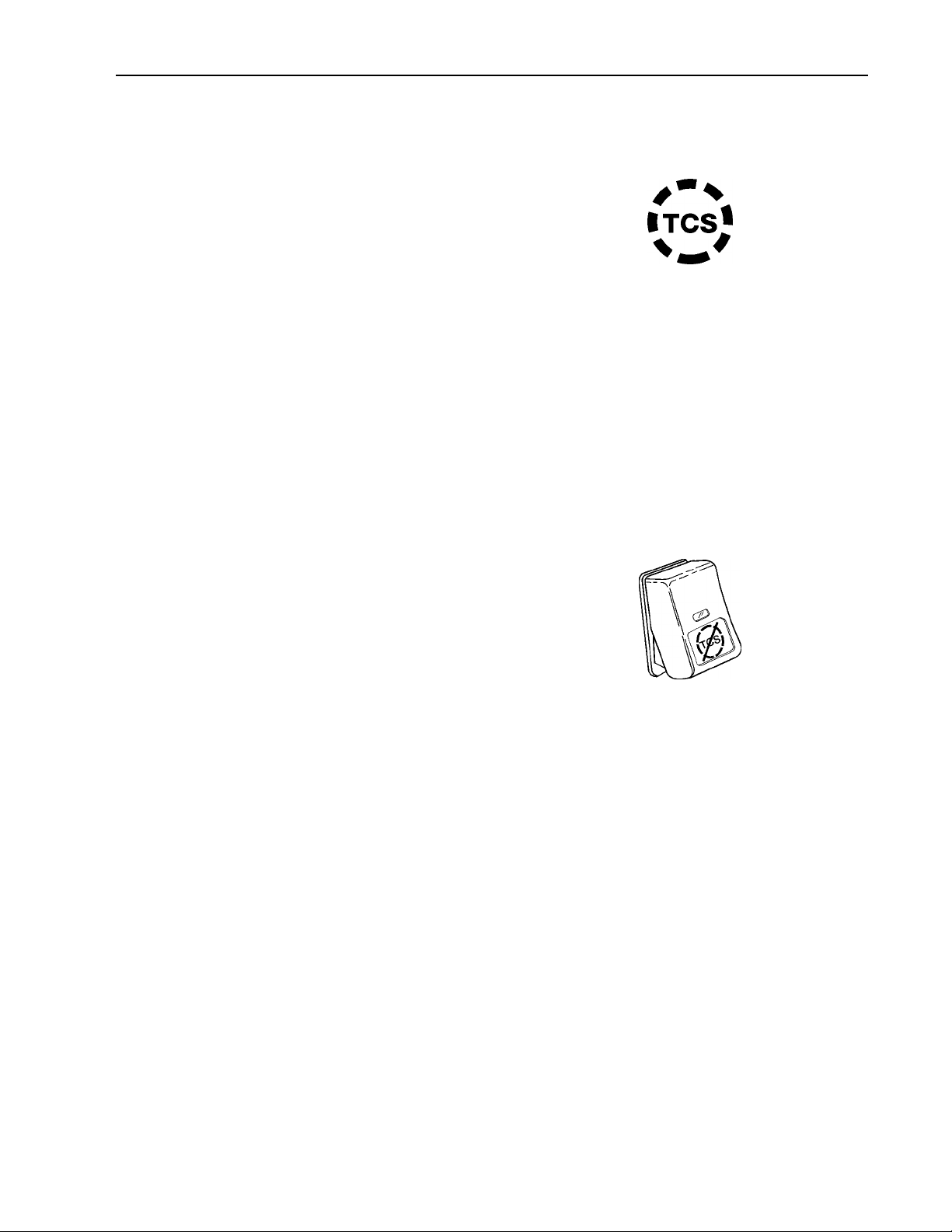
Instruments and Controls 93
Traction Control System Telltale
The amber telltale will blink only when the
Traction Control System (TCS) mud/snow
mode is engaged. At all other times, the
TCS system operates in the background
without indication. The system does not
have an on/off switch. See page 287 for
more information.
The TCS only operates at speeds lower
than 25 mph (40 km/h). The system detects
wheel spin by comparing wheel speeds and
controls the spin by using the brake system
to transfer power to wheels with greater
traction. Under circumstances where all
drive wheels are spinning, the system sends
a signal to the engine control unit to reduce
power.
W3000962
The TCS includes a TCS mud/snow switch
for turning the system off to increase wheel
spin. This function may be desirable in
deep snow or mud to keep the vehicle from
bogging down.
To operate, press in the bottom part of the
switch. The switch stays in this position
and the TCS telltale light blinks to indicate
that the mud/snow mode is engaged. To return to normal TCS operation, press the
bottom part of the switch again and it will
return to rest position.
W3001336
Page 99
94 Instruments and Controls
Auto Neutral Telltale
The Auto Neutral Telltale is for the Allison
WTEC III transmission. The green indicator lights up when the transmission is in
auto neutral. Auto neutral is activated just
before the vehicle comes to a complete stop
(less than 1.5 mph [2.5 km/h]). The gear is
re-engaged shortly (1–2 seconds) after the
brake pedal is released.
Allow for the gear re-engagement when applying throttle; do not increase engine
speed before the transmission has engaged.
If the engine speed is too high, the transmission will not engage.
W3004308
CAUTION
When operating the vehicle on normal
grades (less than 4%), a slight roll-back
can be experienced when the brake
pedal is released and before the transmission re-engages.
NOTE! When operating on severe grades
(more than 5%), the transmission has a
safety feature that can be used. Before releasing the brake pedal, manually press the
“DRIVE” key on the Allison gear selector,
and the gear is re-engaged manually to assist in preventing roll-back.
Page 100
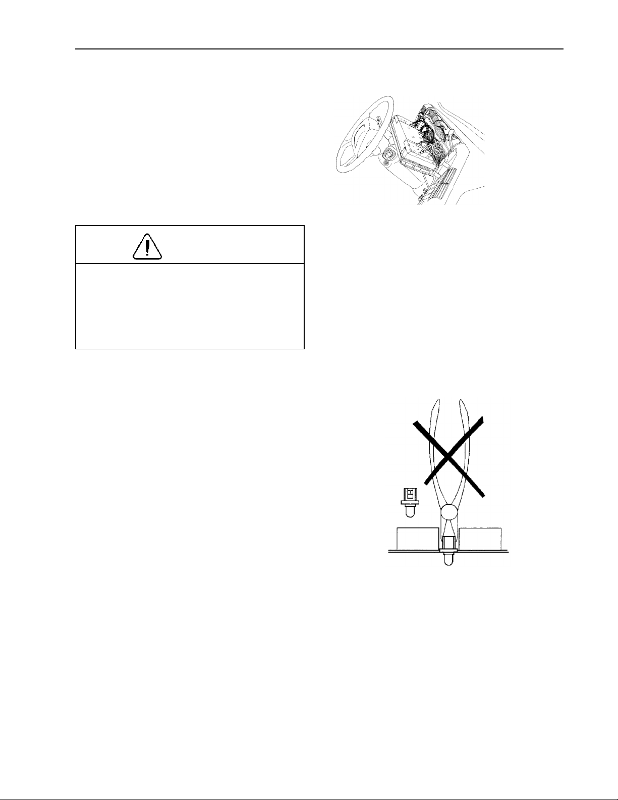
Instruments and Controls 95
Changing Telltale Bulbs In Cluster
NOTE! Before beginning to work, make
sure the vehicle ignition is switched OFF.
If possible, adjust the steering column
back. Remove the two screws at the top of
the instrument cluster and fold the cluster
out and let it rest face-down against the
steering column so the bulbs are accessible.
CAUTION
Do not let the cluster be in the
face-down position for more than maximum 15 minutes. Damage to the gauges
can occur by oil running out of them,
making the gauge reading inaccurate.
W3000842
Do not use any other tools for changing the
bulbs than the correct tool. Using a pair of
pliers could easily cause a short-circuit if
power is on, thereby destroying the circuit
board.
W3001306
 Loading...