

service and maintenance
D4, D6

© 2017 AB VOLVO PENTA
Volvo Penta reserves the right to make changes
Printed on environmentally friendly paper

Table of Content
Safety Information ...................................................................................... 5
Spare parts - safety ................................................................................... 7
General Information .................................................................................. 14
Service Protocol ...................................................................................... 15
Preventive repair ..................................................................................... 16
Genuine Volvo Penta Parts ..................................................................... 23
Illustrations .............................................................................................. 25
Chemical products .................................................................................... 27
Chemical products .................................................................................. 27
Special Tools ............................................................................................. 29
Other Special Equipment ........................................................................ 29
Specifications ............................................................................................ 31
Engine Decals ......................................................................................... 31
Transmission Decals ............................................................................... 32
General Tightening Torques .................................................................... 34
Specifications .......................................................................................... 35
Engine ........................................................................................................ 40
Component location ................................................................................ 41
Maintenance Schedule ............................................................................ 44
General inspection .................................................................................. 45
General advice for electronic protection .................................................. 47
Check software status ............................................................................. 48
Air Filter ................................................................................................... 48
Crankcase Ventilation, Filter Change ...................................................... 49
Compressor, oil level ............................................................................... 50
Compressor oil, Replace ......................................................................... 50
Lubrication System ................................................................................... 52
When you work with Chemicals, Fuel and Lubrication Oil, Change ........ 52
Engine Oil, Level Check .......................................................................... 52
Engine oil, Replace ................................................................................. 54
Oil filter, Replace ..................................................................................... 55
Oil topping up and level check ................................................................ 56
Fuel System ............................................................................................... 64
General ................................................................................................... 64
Fuel filter, Change ................................................................................... 65
Fuel pre-filter ........................................................................................... 66
Fuel system, bleeding ............................................................................. 68
Exhaust System ........................................................................................ 71
Exhaust hose .......................................................................................... 71
Turbocharger, Inspection ........................................................................ 72
Cooling System ......................................................................................... 74
Coolant Level, Checking and Topping Up ............................................... 74
Drive Belt, Replace ................................................................................. 77
Seawater Pump, Impeller, Change ......................................................... 80
Seawater Filter, Check and Cleaning ...................................................... 82
Anodes .................................................................................................... 84
Transmission ............................................................................................. 86
IPS ........................................................................................................... 86
IPS ....................................................................................................... 86
Oil drain, IPS ........................................................................................ 88
47707967 09-2022 © AB VOLVO PENTA 1

Oil filter, IPS ......................................................................................... 88
Oil filler, IPS ......................................................................................... 89
IPS, oil level ......................................................................................... 89
Anode, exhaust outlet (IPS) ................................................................. 90
Propeller ............................................................................................... 91
Propeller shaft seals, replacement ....................................................... 92
Transmission: Oil strainer, inner and outer .......................................... 92
Anodes ................................................................................................. 93
Painting IPS Drives .............................................................................. 94
Reversing gear ....................................................................................... 95
Reversing gear, oil and filter change .................................................... 95
Sterndrive ............................................................................................... 99
Valve block, oil filter, change .............................................................. 101
Sterdrive, hydraulic fluids ................................................................... 103
Sterndrive, oil level ............................................................................. 104
Sterndrive, Draining ........................................................................... 107
Sterndrive, Oil Filling .......................................................................... 109
Sterndrive bellows .............................................................................. 111
Propeller ............................................................................................. 112
Checking Protective Anodes .............................................................. 113
Painting the Drive ............................................................................... 115
Long-Term Storage ................................................................................. 117
Storage instruction for long-term storage of new engine ....................... 119
Cleaning engine and transmission ........................................................ 121
Cold Weather Precautions .................................................................... 123
Checklist ................................................................................................ 125
Battery, Maintenance ............................................................................ 126
Index ......................................................................................................... 129
2 47707967 09-2022 © AB VOLVO PENTA

47707967 09-2022 © AB VOLVO PENTA 3

Safety Information
4 47707967 09-2022 © AB VOLVO PENTA
Safety Information
!
Safety Information
This chapter describes how safety precautions are
presented in the manual and on the product. Read the
chapter through very carefully before you start the
engine or do any maintenance or service. It has to do
with your safety; an incorrect operation can lead to
personal injury and damage to products or property. It
also gives you an introduction to the basic safety rules
for using and looking after the engine.
Safety texts have the following order of priority:
DANGER!
Indicates a hazardous situation, which, if not avoided, result in death or serious injury.
WARNING!
Indicates a hazardous situation, which, if not avoided, could result in death or serious
personal injury.
CAUTION!
Indicates a hazardous situation, which, if not avoided, could result in minor or moderate
personal injury.
If anything remains unclear or if you are unsure of
something, contact your Volvo Penta dealer for
assistance.
IMPORTANT:
Always follow local safety instructions and
regulations.
IMPORTANT:
Indicates a situation, which, if not avoided, could result in property damage.
NOTICE! Used to draw attention to important information that facilitates work or
operations.
This symbol is may be used on the product to call your attention to the fact that this is
safety information. Always read such information very carefully.
Make sure that warning and information symbols on the engine are clearly visible and
legible. Replace symbols that have been damaged or have been painted over.
In some cases, this symbol is used on our products and refers to important information
in the Operator’s Manual.
47707967 09-2022 © AB VOLVO PENTA 5

Safety Information
Most chemicals such as engine and transmission oils,
glycol, petrol and diesel oil and chemicals used in
workshops such as degreasing agents, paint and
solvents are harmful to health.
Carefully read the instructions on the product
packaging! Always follow the safety regulations, such
as the use of protective masks, goggles, gloves, etc.
Make sure that other personnel are not exposed to
substances that are hazardous to health. Ensure good
ventilation.
Manage used and leftover chemicals in the prescribed
manner.
Personal safety equipment
CAUTION!
Always use appropriate safety equipment. Personal
protective equipment does not eliminate the risk of
injury but it will reduce the degree of injury if an
accident does happen.
P0024482
Some examples are ear protection, eye and face
protection, protective footwear, personal protective
equipment, head protection, protective clothing,
gloves and respirators.
WARNING!
Ensure that all machine guards and safety devices are
in place and are functional.
CAUTION!
Never use tools or products that show signs of
damage.
Protect your eyes
CAUTION!
Wear safety glasses.
Always wear safety glasses if there is a risk of
splintering, sparks and spray from the electrolyte (socalled battery acid), or other chemicals. Your eyes are
very delicate and damage can result in loss of sight!
Protect your skin
CAUTION!
Risk of skin damage.
Avoid getting oil on your skin! Prolonged or repeated
exposure to oil can dry out the skin. Thereafter,
irritation, dryness and eczema and other skin problems
may occur.
Use protective gloves and avoid oil-soaked clothes
and rags. Wash regularly, especially before eating.
Wear suitable protective creams to prevent skin from
drying out and to facilitate cleaning.
6 47707967 09-2022 © AB VOLVO PENTA
P0024470
Safety Information
Fire safety
WARNING!
Fire and Explosion Risk!
Accidental spark could ignite fuel vapors.
All fuels – as well as many lubricants and chemicals –
are flammable. Do not allow open flames or sparks
near them. Smoking forbidden! Hydrogen from the
batteries is also very flammable and explosive in
certain mixture with air.
Ensure that the workplace is well ventilated and take
the necessary precautions before welding or grinding
begins. Always ensure that there is a fire extinguisher
close at hand in the work area.
Spare parts - safety
WARNING!
Always use Volvo Penta genuine spare part to
minimize the risk of an explosion or fire.
Components in fuel systems and electrical systems on
Volvo Penta engines are designed and manufactured
to minimize the risk of explosions and fire, in
accordance with applicable legal requirements.
Used oils, filters and chemicals etc.
WARNING!
Risk of fire.
Store fuel soaked rags and other flammable material
so that there is no danger of them catching fire.
Oil-soaked rags can spontaneously ignite under
certain circumstances.
IMPORTANT:
Used fuel and oil filters are environmentally hazardous
waste and must be taken to an approved waste
management facility for correct handling, as must any
used lubricating oil, contaminated fuel, paint residue,
solvents, degreasers and wash residue.
Prevent start of the engine
WARNING!
Immobilize the engine by turning off the power supply
with the main switch(es) and lock it (them) in the off
position before starting work. Place a warning notice at
the main switch.
If the engine is equipped with BMS (Battery
Management System), always disconnect both battery
cables from the battery terminals.
47707967 09-2022 © AB VOLVO PENTA 7
Safety Information
P0024481
P0024808
Ventilation when running the engine
WARNING!
Only start the engine in a well-ventilated area. If
operating the engine in a closed area ensure that there
is exhaust ventilation leading out of the work area to
remove exhaust gases and crankcase ventilation
emissions.
The engine must not be operated in areas where there
are explosive materials or stored gas.
Rotating parts and hot surfaces
DANGER!
Working with or approaching a running engine is a
safety risk. Watch out for rotating components and hot
surfaces.
If the engine is in operation and operates another
device, you must not, under any circumstances,
staying close to the engine.
Work on running engines is strictly prohibited. There
are however adjustments that require the engine to be
run. Approaching a running engine is a safety risk.
Loose clothing and long hair can get caught in the
rotating parts; careless movements or a dropped tool
can lead to serious personal injury.
Be careful to avoid hot surfaces (exhaust pipes,
turbochargers, charge air manifolds, start elements
etc.) and hot fluids in pipes and hoses on engines that
are running or have just stopped. Re-install all
protective covers that were removed during
maintenance work before starting the engine.
Information on the engine
IMPORTANT:
Make sure that all warning and information decals on
the product are always visible. Replace decals which
have been damaged or painted over.
8 47707967 09-2022 © AB VOLVO PENTA
P0024483
P0024688
Safety Information
Prohibition on use of start spray
WARNING!
Never use start spray or similar agents to start an
engine. This may cause an explosion in the inlet
manifold. Risk of personal injury.
Before start of engine
WARNING!
Never start the engine if there is reason to suspect fuel
and/or gas leaks, or if there is explosive material
nearby.
IMPORTANT:
Only start the engine with the air filter and protective
caps fitted. Foreign objects in the inlet line could cause
machine damage. Also make sure that no tools or other
parts have been left next to the engine.
WARNING!
Never start the engine with the valve cover removed.
There is a risk of personal injury.
For engines with turbochargers, the rotating
compressor turbine can in addition cause serious
personal injuries.
Before any work on the electrical system
WARNING!
Always stop the engine first. Then disconnect the
current at the main switches and any external power
supply before working on the electrical system – to
minimize the risk of electrical hazards.
IMPORTANT:
Never disconnect the current using the main switches
when the engine is running or by disconnecting the
battery cables.
The alternator and electronics could be damaged.
Avoid damage to the engine control
module and other electronics
IMPORTANT:
Switch off the main switch before connecting or
disconnecting a connector.
Before any work on the cooling system
WARNING!
Stop the engine and let it cool before starting work on
the cooling system. Hot fluids and hot surfaces can
cause burns.
47707967 09-2022 © AB VOLVO PENTA 9
Safety Information
P0024484
Risk of water penetration/sinking
WARNING!
If a launched boat is equipped with sea water tap and
safety valve, ensure that these are closed before any
work is allowed to begin on the cooling system.
Remember to open the tap and valve before starting
the engine!
Hot coolant under pressure
CAUTION!
Hot coolant can cause burns. Avoid opening the filler
cap for the coolant when the engine is still hot. Steam
or hot coolant can spray out and system pressure is
lost.
Open the filler cap slowly, and release the pressure in
the cooling system if the filler cap or valve has to be
opened, or if a plug or coolant hose must be removed
from a hot engine.
P0024488
Hot oil under pressure
CAUTION!
Hot oil can cause burns. Avoid getting hot oil on the
skin. Ensure that the lubrication system is not
pressurized before starting any work. Never start or
operate the engine without the oil filler cap is on. There
is a risk that hot oil can spray out.
At any leak detection on the fuel system
WARNING!
Wear safety goggles!
Be extremely careful when searching for leaks in the
fuel system high-pressure circuits. There is very high
pressure in the jet from pipes and injectors. The fuel
may penetrate the tissue and cause serious risk of
blood infection (septicemia).
Handling of fuel pipes
IMPORTANT:
High pressure pipes for fuel must not be bent or
straightened under any circumstances. Cracks may
occur. Damaged pipes must be replaced.
Before any work on the fuel system —
Cleanliness
IMPORTANT:
Take great care to keep the fuel system components
clean. Even minimal amounts of dirt can cause engine
breakdown.
10 47707967 09-2022 © AB VOLVO PENTA
P0024468
Safety Information
Safe handling of batteries
WARNING!
Risk of fire and explosion. Never allow an open flame
or electric sparks near the batteries.
A spark caused by an incorrectly connected battery
can be sufficient for the battery to explode resulting in
serious injury and damage.
Do not touch the connections during a starting attempt.
Spark hazard! Do not lean over batteries.
Correct polarity of the batteries
IMPORTANT:
Make sure that the positive (+) and negative (–) battery
cables are correctly connected to the corresponding
battery terminals. Wrong connection may cause
severe damage to electrical equipment.
Risks of electrolyte in batteries
WARNING!
Always wear protective goggles when charging or
handling batteries.
Battery electrolyte is highly corrosive.
Rinse immediately with copious amounts of water if the
electrolyte gets in your eyes. Search directly after the
rinsing help by medical staff.
If it comes electrolyte to unprotected skin, wash
immediately with soap and water.
After finished work with the engine
IMPORTANT:
Always perform a leakage and function check.
Cleaning the engine and components
NOTICE! Follow the instructions Cleaning engine and
transmission, page 121.
P0026213
Cleanliness for sensitive components
IMPORTANT:
Observe meticulous cleanliness when handling
system components.
Even minimal amounts of dirt could cause a
breakdown.
47707967 09-2022 © AB VOLVO PENTA 11
General Information
P0024485
Lifting the engine
WARNING!
Never work alone when removing heavy components,
even when using lifting devices such as locking tackle
lifts.
IMPORTANT:
When using a lifting device, two people are usually
required to do the work – one to take care of the lifting
device – and the other to ensure that components are
lifted clear and not damaged during the lifting
operations.
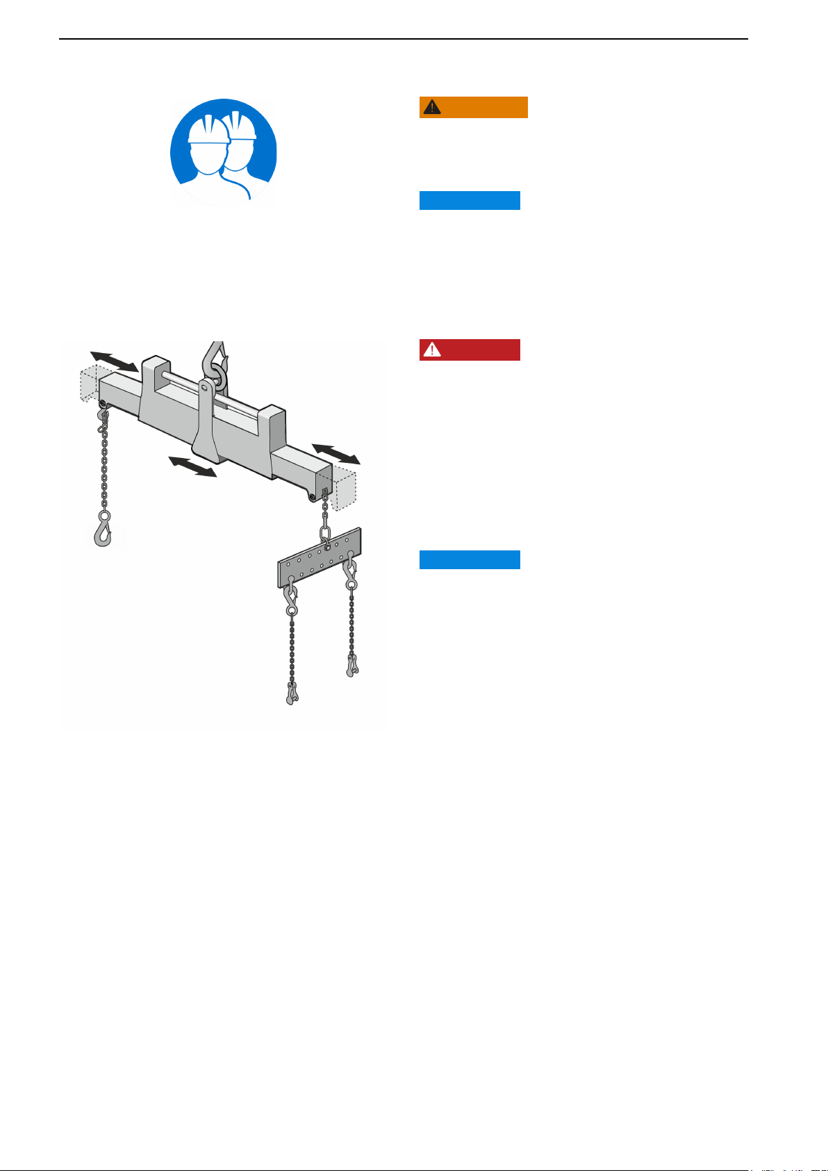
Proper lifting equipment
DANGER!
The existing lugs on the engine should be used for
lifting. Always check that the lifting equipment used
is in good condition and has the load capacity to lift
the engine (engine weight including transmission and
extra equipment). For safe handling and to avoid
damaging components fitted to the top of the engine,
the engine must be lifted with a correctly adjusted lifting
boom.
Never perform any work on an engine that is only
suspended from the lifting equipment.
P0024689
Example of an adjustable lifting yoke and a lifting tool.
IMPORTANT:
All chains or wires must run parallel to each other and
as perpendicular to the engine as possible. If other
equipment attached to the engine has altered its center
of gravity, special lifting devices may be needed to
obtain the correct balance for safe handling.
12 47707967 09-2022 © AB VOLVO PENTA

General Information
47707967 09-2022 © AB VOLVO PENTA 13

General Information
General Information
General information
This service and maintenance manual contains
descriptions and instructions for the service of the
above-mentioned Volvo Penta products in their
standard models. The design and servicing items may
vary between different products. Applicable service
intervals and service procedures are described in the
maintenance schedule for the product.
The product designation, serial number and
specification are indicated on the engine decals or
type plate. This information must always be provided
in all correspondence concerning the product.
The manual has been produced primarily for use in
Volvo Penta workshops. It is assumed that persons
using the manual have fundamental knowledge of the
product and are capable of carrying out mechanical
and electrical work to industry standards.
Volvo Penta continually develops its products. We
therefore reserve the right to make changes.
All of the information in the manual is based on
product data available when the manual was
published.
NOTICE! The owner is responsible for ensuring that
scheduled maintenance is carried out. Warranty
claims to Volvo Penta may be declined if neglected
maintenance results in faults in the specified product.
Refer to the warranty terms supplied with the engine.
Specific terms for the U.S. market
This engine is certified as being in compliance with
federal and Californian exhaust restriction
regulations. Parts related to exhaust restrictions are
covered by the warranty commitment for exhaust
restricting systems. Terms and the parts covered are
specified under "What is covered by the warranty
undertaking for emissions” in “Emission Control
System Warranty Statement”. Repairs and service
covered by the warranty are carried out by an
authorized Volvo Penta distributor or dealer at no
charge for diagnostics, labor or parts using genuine
Volvo Penta parts in all areas of the exhaust restriction
system covered by the warranty and found to be
defective.
The use of the service and repair workshop other than
a Volvo Penta authorized distributor or dealer or the
use of exhaust-related components from other
manufacturers than Volvo Penta do not affect the
scope of the warranty undertaking for emissionrestricting systems. If emission-related components/
items are included in scheduled service, such parts
are marked with a diamond (♦) in the maintenance
schedule and service must be carried out at the
specified intervals in order to meet the requirements
of the warranty undertaking for emission-restricting
systems. The full warranty terms can be found in
“Emission Control System Warranty Statement”.
14 47707967 09-2022 © AB VOLVO PENTA

Certified engines
The engine is exhaust-certified, and if it is used in
an area where exhaust emissions are regulated
by law, this places special demands on the care
and maintenance of the engine.
NOTICE! Neglect or failure to follow the items
required here may invalidate the engine emissions
certificate.
This means that AB Volvo Penta will no longer be able
to assume liability for engine specification
compliance with the certified model. Volvo Penta is
not responsible for damages or costs arising as a
result of this.
• Certification means that an engine type has
been inspected and approved by the competent
authorities. The engine manufacturer
guarantees that all engines made of the same
type are equivalent to the certified engine.
• It is the responsibility of the user to make sure
no intentional misuse of the engine takes place.
• Volvo Penta maintenance and service intervals
must be followed.
• All faults must be remedied as soon as possible.
• Only use genuine Volvo Penta replacement
parts or parts of the same quality as Volvo Penta
replacement parts.
General Information
Explanation of the relationship between
service intervals and operating
conditions
Because operating conditions may vary depending
on how the component is used, it is important that the
service interval (expressed in hours or months) is not
exceeded.
Example: 1000 hours / 24 months. Whichever is the
sooner applies. If the component is used for 1000
hours in 18 months, the service must be carried out
when the 1000-hour interval is reached.
This is to retain the component’s best quality and
service life. The warranty will be void if this is not
complied with.
Typical examples are: Propeller shaft seals operating
in sandy waters. Air filters exposed to heavily polluted
air
Action codes used in the service schedule:
C = Cleaning
R = Replacement
A = Adjustment
L = Lubricate
I = Inspection (includes where necessary also
adjustment, cleaning, lubrication and replacement)
• The engine may not be converted or modified in
any way, except with accessories and service
kits which Volvo Penta has approved for the
engine.
• Volvo Penta recommends that service on
injection pumps, pump settings and injectors
always be carried out by a qualified workshop.
• No changes may be made to the installation of
the exhaust pipe and engine air inlet ducts.
• Any tampering with the engine will hamper EU
type-approval of the engine concerned.
• No warranty seals (if present on the product)
may be broken by unauthorized persons.
Service Protocol
To maintain the functionality of the product Service
Protocol shall be followed. The owner or other persons
with sufficient technical competence may carry out
some measures in accordance with Service Protocol.
Contact an authorized Volvo Penta dealer in the case
of uncertainty as to how service work must be
performed.
Service Protocol contains the necessary maintenance
points for your engine in a single document. See more
on Volvo Penta‘s website: vppn.volvo.com and
Product Center for online service protocol.
47707967 09-2022 © AB VOLVO PENTA 15
General Information
Preventive repair
Here is an overview of the components that may be included in preventive maintenance. May vary depending on
the engine's design and construction.
These components form the basis for calculating service contracts and the costs in the service calculator in
Product Center.
Fuel system
Fuel pump
Unit injectors
P0026295
P0026296
Exhaust system
Turbocharger, low-pressure
Turbocharger, high pressure
Overflow valve (Lisk)
Silencer
Diesel particulate filter (DPF), replacement
After-treatment system
Pump unit
Dosage valve
16 47707967 09-2022 © AB VOLVO PENTA
P0026297
General Information
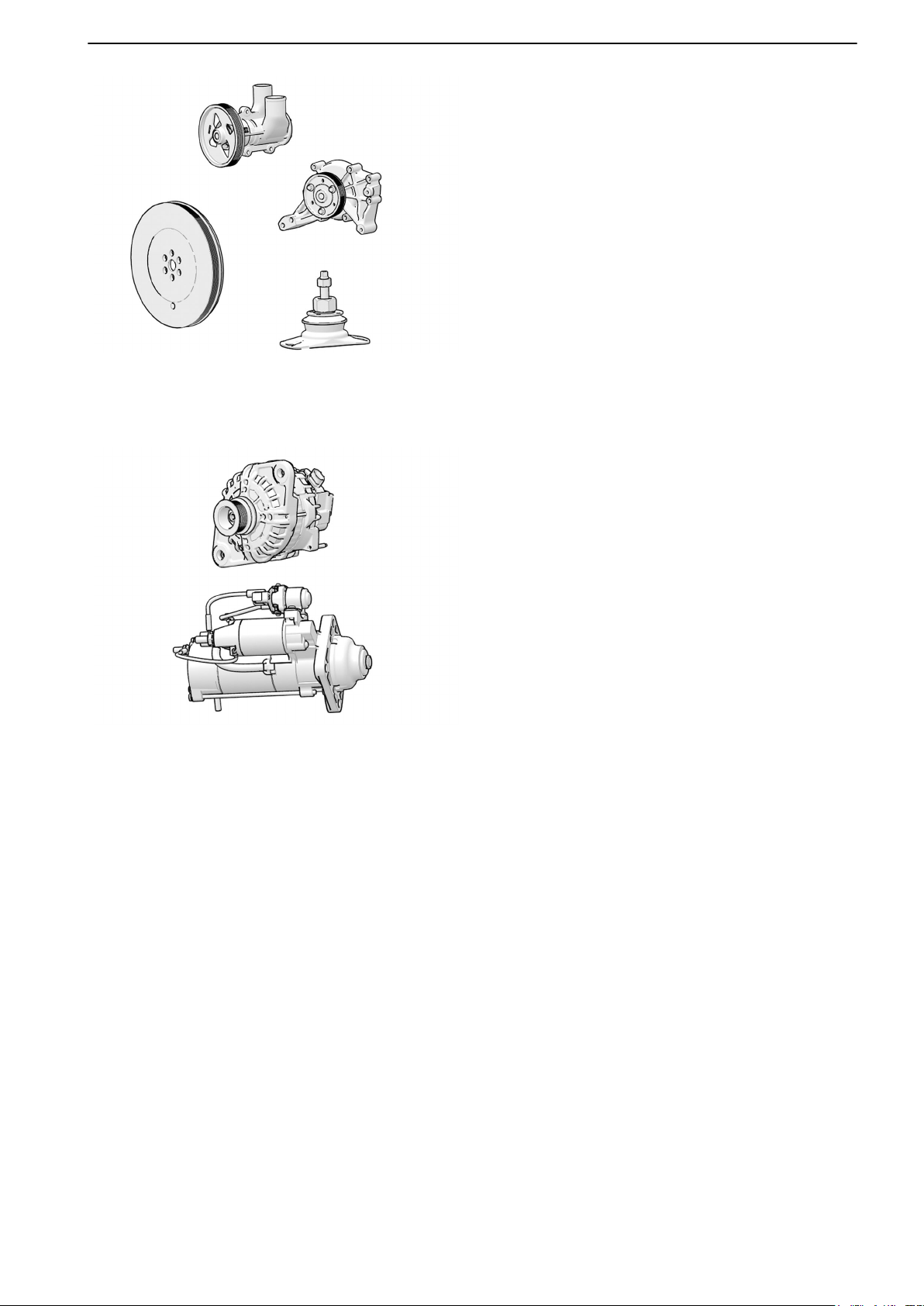
Cooling system
Seawater pump
Coolant pump
Engine
Vibration dampers
Engine pads, kit
Electrical system
Alternator
Starter motor
P0026298
47707967 09-2022 © AB VOLVO PENTA 17
General Information
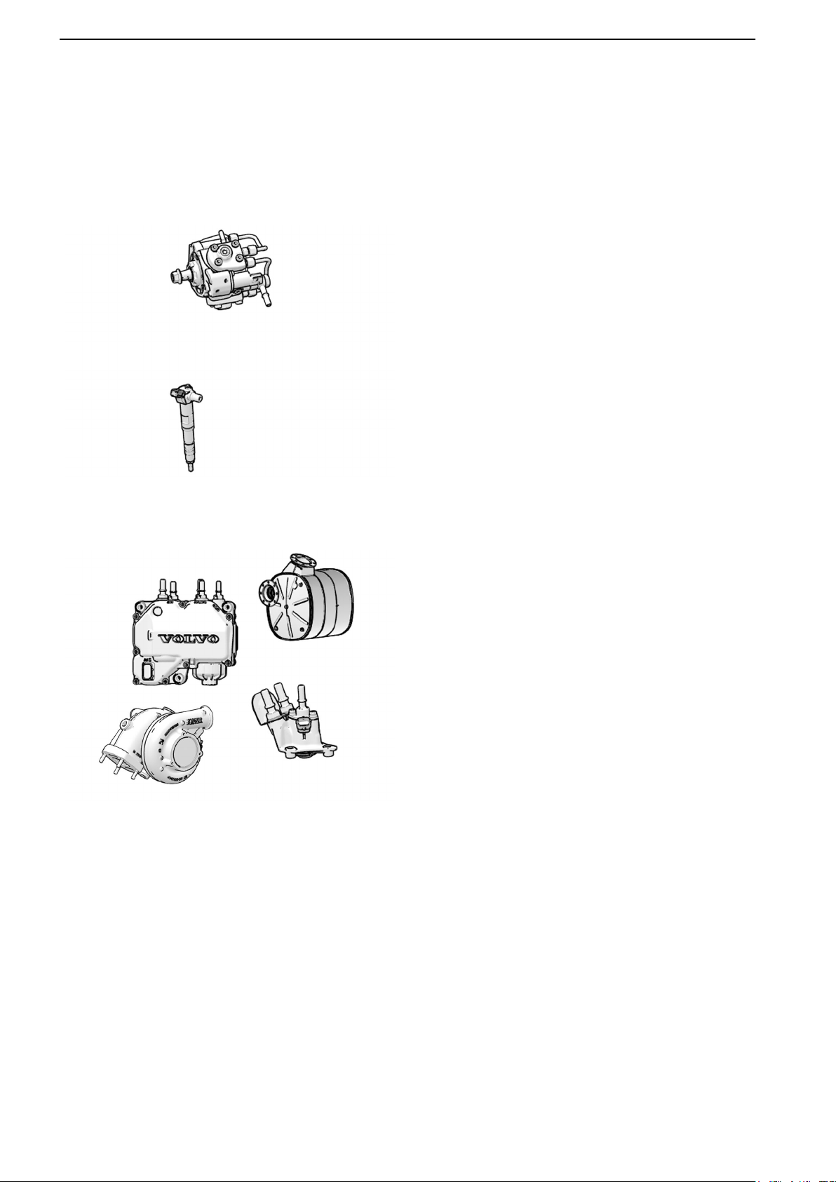
Engine, overhaul
Here is an overview of the components that may be included in a complete overhaul. May vary depending on the
engine's design and construction.
E.g. liners may not be replaced on certain engines. In this case, cylinders must be measured to see if new pistons
can be installed or if the engine block should be replaced.
The components below provide the basis for calculating service contracts and the costs in the service calculator
in Product Center.
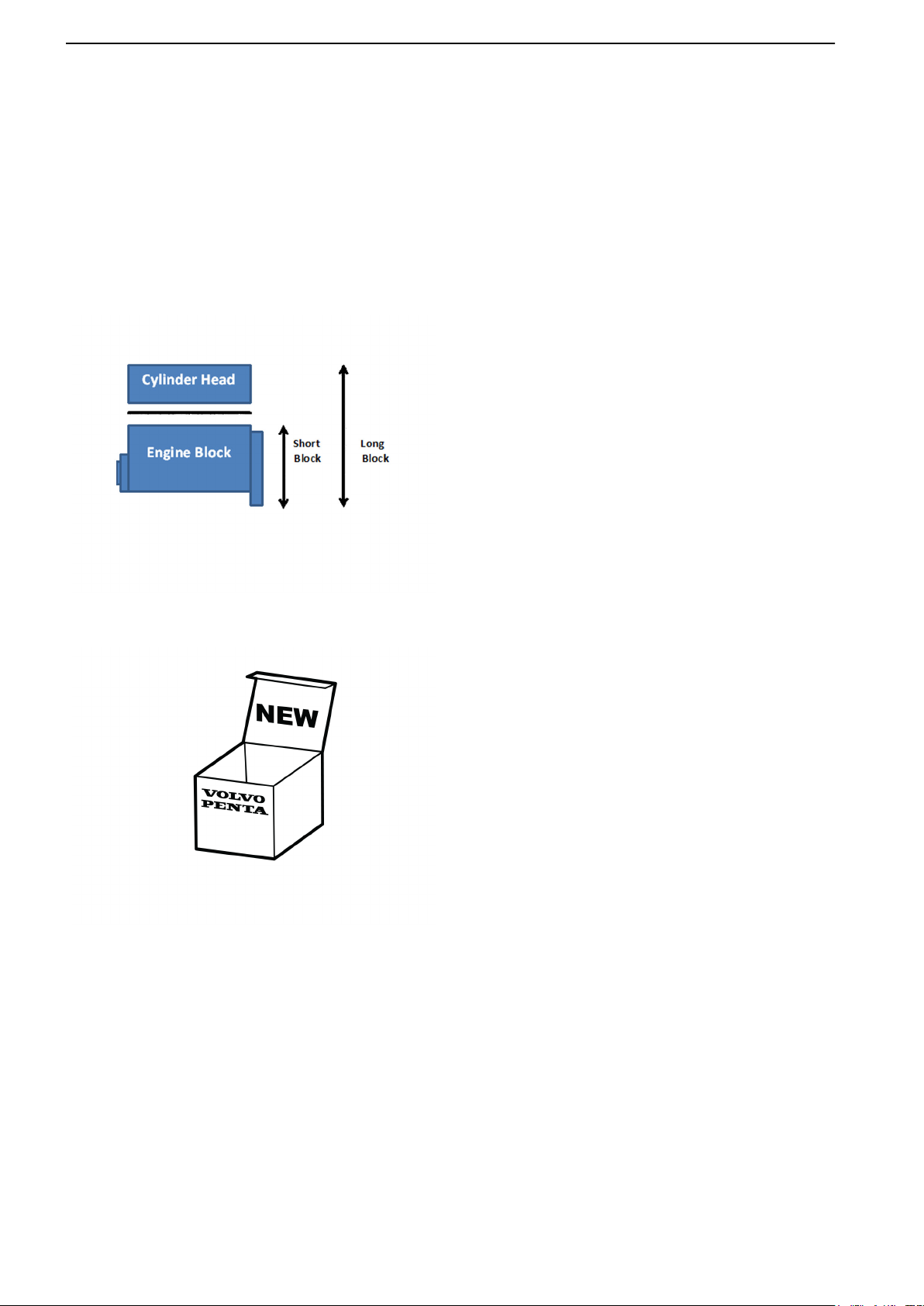
Engine: May be overhauled twice, after which the engine is considered spent and is replaced by a long block or
new engine.
Overhaul
Long block
Short block
Cylinder head (replacement)
Cylinder head, gasket
P0026299
P0026300
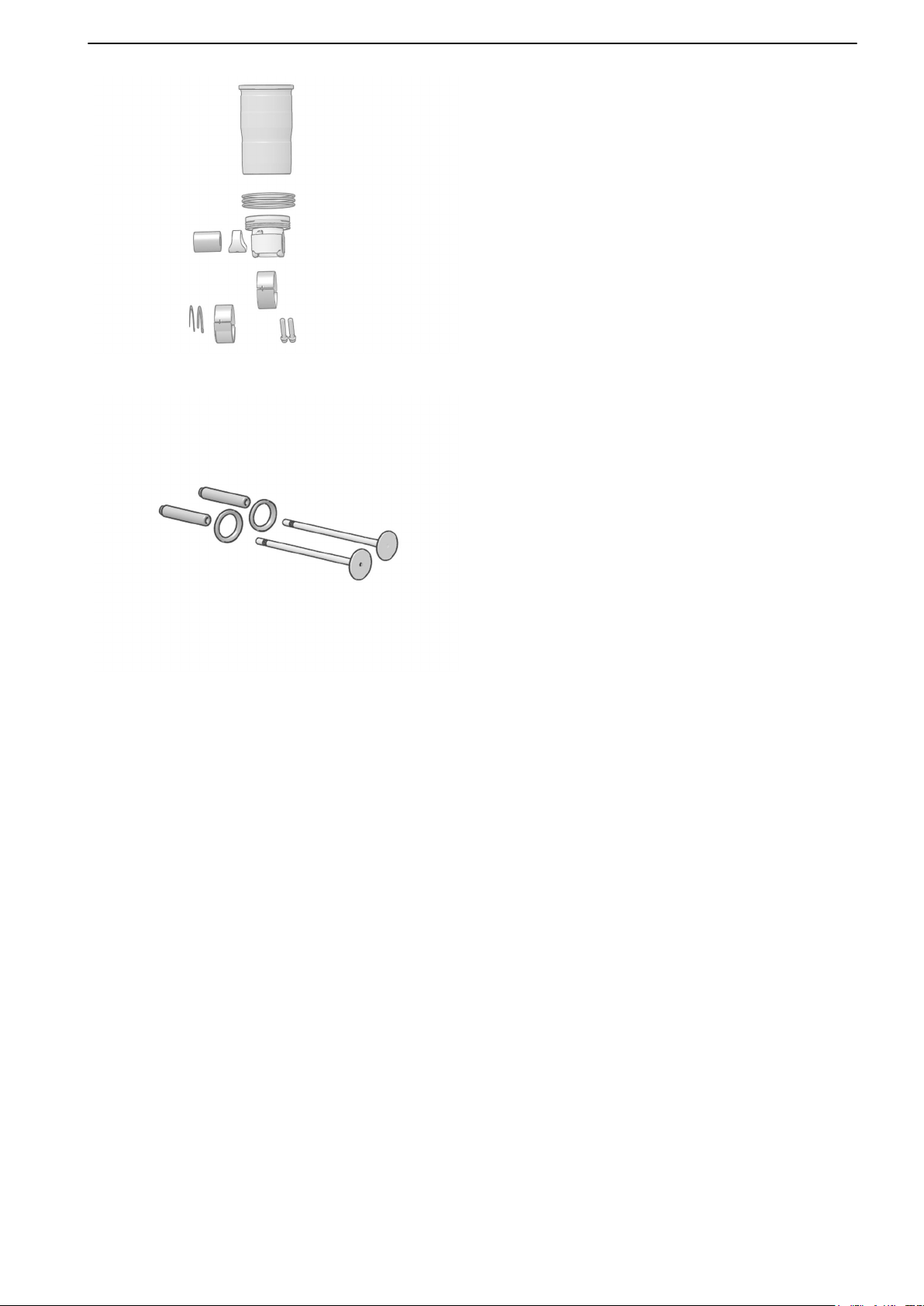
Engine, overhaul kit
Cylinder head, overhaul kit
Gaskets, kit
Flat gaskets
Valve cover, gasket
18 47707967 09-2022 © AB VOLVO PENTA
P0026301
General Information
Cylinder liners, kit
Main bearings, kit
Big end bearings, kit
Thrust washers, kit
Camshaft bearings, kit
Exhaust valve
Valve seat
P0026302
47707967 09-2022 © AB VOLVO PENTA 19
General Information
Transmission, overhaul
Here is an overview of the components that may be included in a complete overhaul/replacement. May vary
depending on the transmission's design and construction.
The components below provide the basis for calculating service contracts and the costs in the service calculator
in Product Center.
The transmission is overhauled once, then the complete unit is replaced
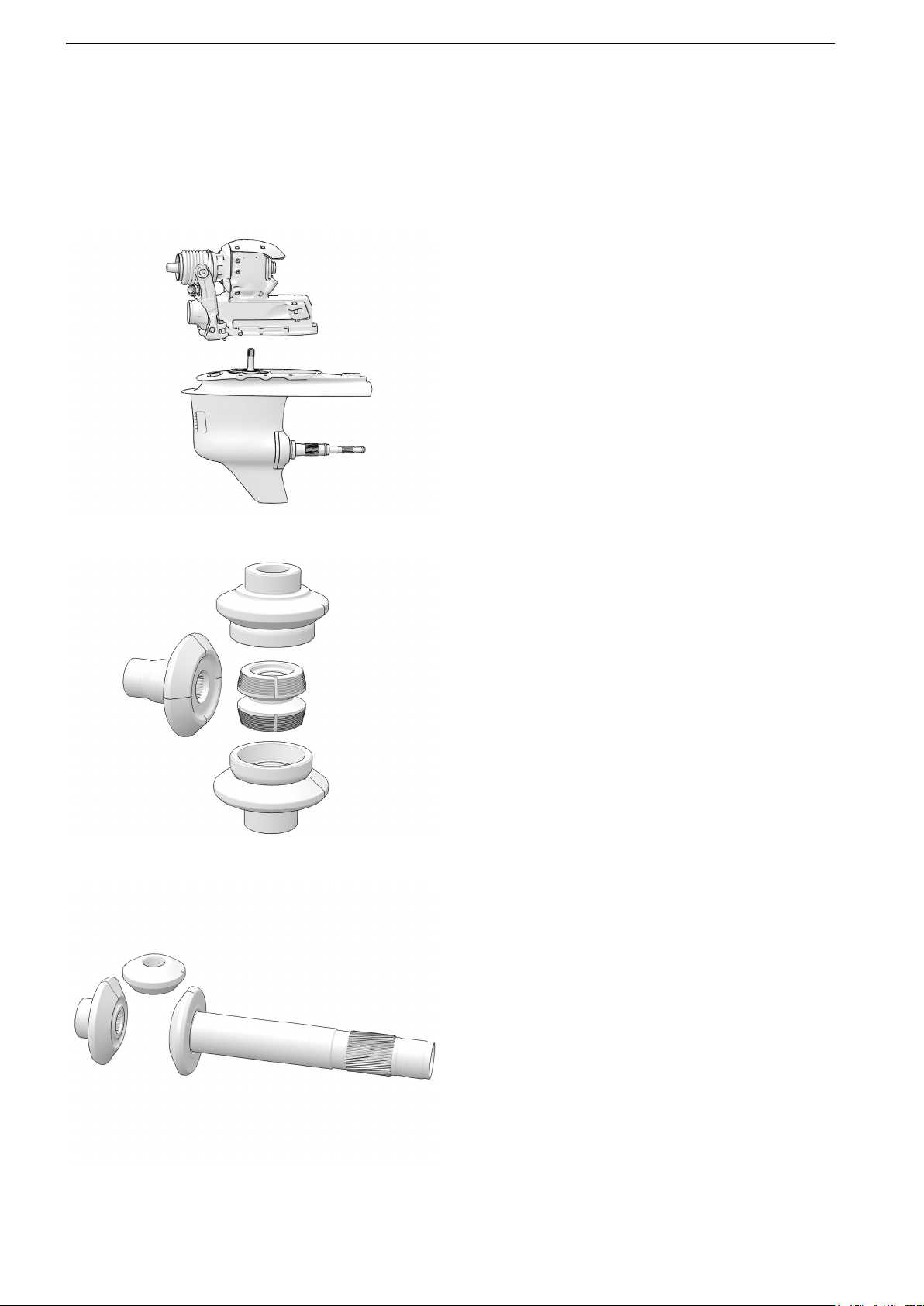
Overhaul, Aquamatic
Aquamatic sterndrive, replacement
Upper gear
Lower gear
P0026303
P0026304
Repair, Aquamatic
Upper gear, kit
Sliding sleeve
Lower gear, kit
P0026305
20 47707967 09-2022 © AB VOLVO PENTA
P0026306
General Information
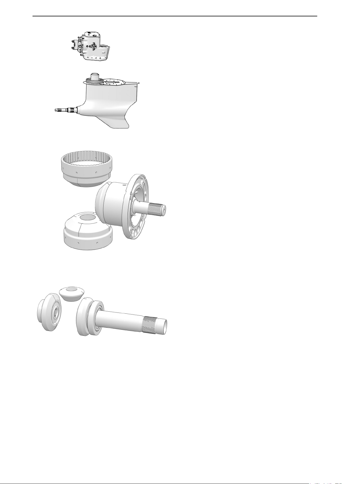
Overhaul, IPS
IPS Drive, replacement
Upper gear
Lower gear
Repair, IPS
Upper gear, kit
P0026307
P0026308
Lower gear, kit
47707967 09-2022 © AB VOLVO PENTA 21
General Information
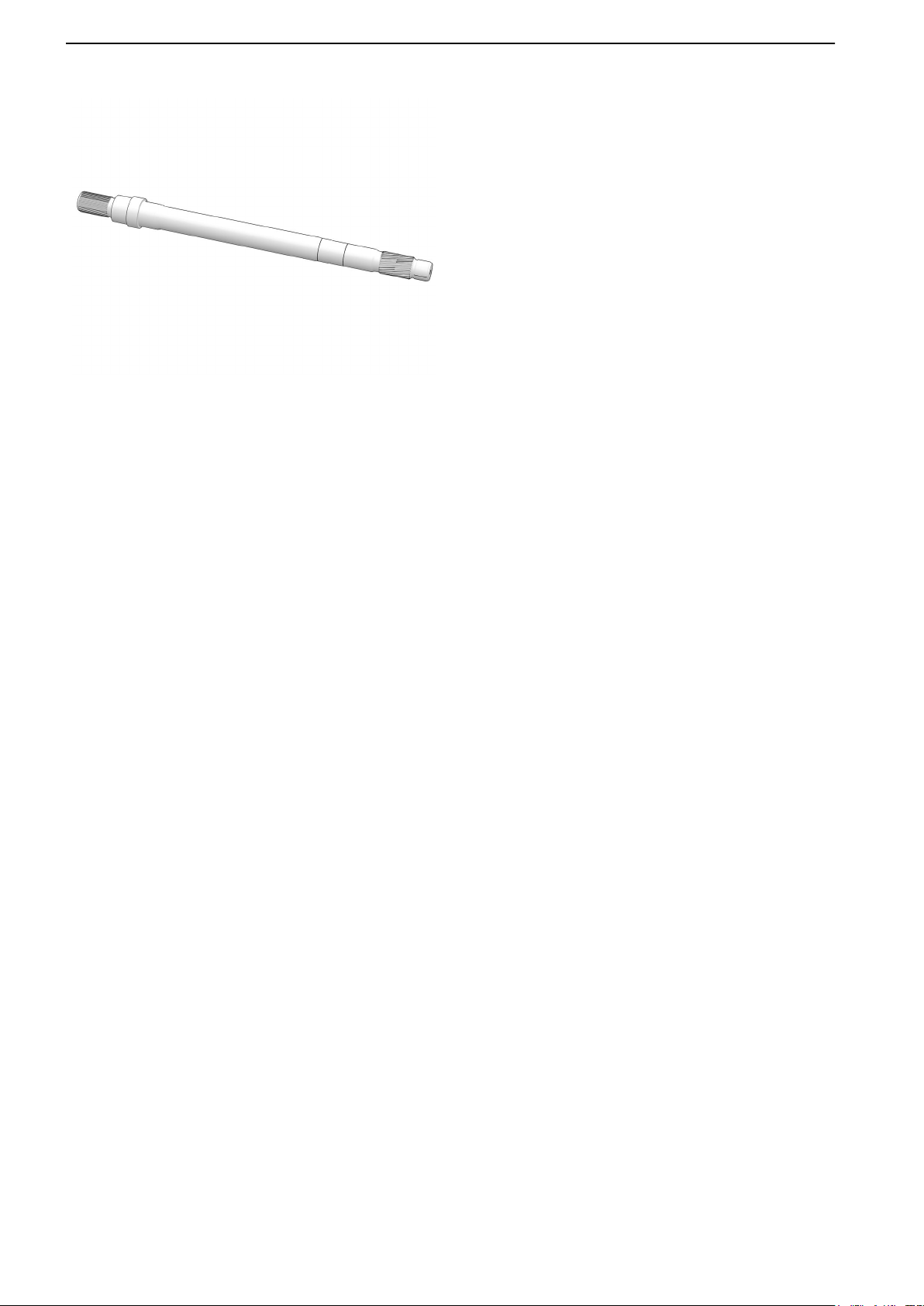
P0026309
Propeller shaft
22 47707967 09-2022 © AB VOLVO PENTA

General Information
Genuine Volvo Penta Parts
Volvo Penta products are designed and manufactured
to achieve the highest quality. All parts are
manufactured so that together they provide the best
possible reliability. For this reason, we always
recommending the use of Genuine Volvo Penta
Partsas they are manufactured based on the same
stringent specifications as the factory-installed parts in
Volvo Penta powertrains.
Lube oils
Volvo Penta supplies a wide range of lubricants
developed especially for Volvo Penta engines. VDS
(Volvo Drain Specification) is a Volvo standard that
specifies Volvo’s oil grade requirements. We
recommend the use of the specified oil to ensure
engine function and a long service life.
Transmission oil
In a marine environment it is vitally important that the
correct gear lubricant is used for the product
concerned.
In Volvo Penta's extensive testing we pick out those
oils that meet our requirements for functionality and
that within the oil change intervals ensure the product’s
service life.
While oils from various suppliers meets both SAE class
(viscosity) and API class (quality), their additives often
differ. Additives can be up to 35% of the total volume,
and are crucial to how oil can handle a given water
content while still maintaining the necessary
lubricating properties. The additives also affect the
friction in, for example, the IPS unit clutch assembly.
The correct oil is crucial for the proper functioning of
the transmission.
IMPORTANT:
It is extremely important not to use other oil than
specified for the IPS unit.
NOTICE! Volvo Penta will deny all warranty claims if it
emerges that the wrong oil has been used in the IPS
unit.
NOTICE! For reverse gears, the oil change intervals
and maintenance instructions recommended by the
manufacturer must be adhered to.
Coolant
The main function of a coolant is to absorb heat from
the engine. The coolant also protects against freezing,
lime deposits and corrosion. Volvo Penta Coolant VCS
(yellow) and Volvo Penta Coolant (green) are two
completely different types of coolants, which contain
different types of inhibitors. Different types of coolants
(colors) must not be mixed.
47707967 09-2022 © AB VOLVO PENTA 23

General Information
If the concentrated coolant must be diluted with water,
the water's chemical composition may impair the
corrosion protection. In areas with high levels of
sodium and calcium in tap water, the coolant must be
diluted with distilled water. Alternatively, Volvo Penta
coolant is available for purchase ready diluted.
Protection against
Mixing the
concentrated coolant
40 % -25 °C
46 % -30 °C
54 % -38 °C
60 % -46 °C
NOTICE! It is important to use coolant with a
concentration of 40-60 % in the cooling system even
where there is no risk of freezing. The coolant also
prevents corrosion and deposits. A mixture with a
concentration above 60 % will impair antifreeze
protection.
freeze bursting down
to:
24 47707967 09-2022 © AB VOLVO PENTA

Colors used in illustrations
Most illustrations include a highlighted component
which is secured by a bolt or similar as part of a (light
gray) engine or transmission.
Chemical products
Illustrations
• Highlighted components
(blue)
• Fastener
(red)
• Assembly
(light gray)
• Background
(white)
• Special tools
(yellow)
• Seals
(green)
(as of 06/2018)
P0022106
Other types of symbols used in the images are
divided into the following categories:
• Safety
• Important
• Cleanliness
• Position
• Movement
• Measured value
• Tools
• Chemicals
• Sealant
• Units
47707967 09-2022 © AB VOLVO PENTA 25

Chemical products
26 47707967 09-2022 © AB VOLVO PENTA
Chemical products
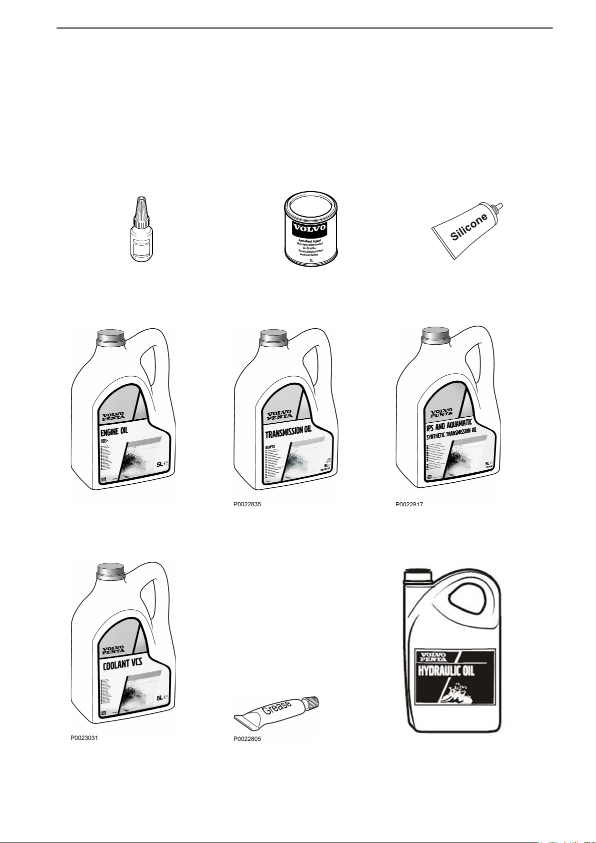
P0001869
Thread locking fluid Corrosion protection Sealant
Special Tools
Chemical products
The following is a selection of Volvo Penta
recommended chemical products. The products are
available for purchase at regional Volvo Penta
dealerships. Deviations may occur in the range, see
Specifications.
For correct part numbers, refer to the Parts catalogue.
Engine oil Transmission oil IPS synthetic gear lubricant
VCS Coolant Grease ATF oil
47707967 09-2022 © AB VOLVO PENTA 27

Special Tools
28 47707967 09-2022 © AB VOLVO PENTA

Special Tools
Specifications
Other Special Equipment
There are special equipment and tools to be used
when working with the engine. For some operations/
service points special tools are required in order to
carry out the work in a correct manner.
3889988 Adapter 22767251 Hose
47707967 09-2022 © AB VOLVO PENTA 29

Specifications
30 47707967 09-2022 © AB VOLVO PENTA

Specifications
Specifications
Engine Decals
There are type plates on the engine, and in the case of
marine applications, also on the drive lines. Some of
the type plates are marked with identity numbers. This
information should always be used as a reference
when ordering service and replacement parts or
contacting Volvo Penta retailers.
1 Certification/Transom ID 3 Serial #
2 CHASSIS ID 4 Product ID
47707967 09-2022 © AB VOLVO PENTA 31

Specifications
Transmission Decals
IPS unit
1 Product ID
2 CHASSIS ID
Reverse Gear
1 Reverse gear ID
32 47707967 09-2022 © AB VOLVO PENTA

Specifications
Stern drive
1 Stern drive ID
Electrical rudder actuator
1 Product information
2 CHASSIS ID
3 Product ID
47707967 09-2022 © AB VOLVO PENTA 33

Specifications
Bolt Nm
M6 standard bolt 10
M8 standard bolt
M10 standard bolt
M12 standard bolt
M14 standard bolt
M16 standard bolt
NOTICE! Check the bolts intended for
installation Damaged bolts with e.g. shear
marks under the heads, must be scrapped.
24
48
85
140
220
General Tightening Torques
34 47707967 09-2022 © AB VOLVO PENTA

Specifications
Volvo Penta products, all markets excluding North America
Oil quantity in engine, including filter
D4
D6
VDS-4.5 SAE15W-40
Part number: 23909459
Part number: 23909460
Part number: 23909461
Part number: 23909462
Oil volume
DPH-D1 drive
(differs between versions: A - B - C - D)
DPR drive 4.2 liters
12 liters
20 liters
1 liter
5 liters
20 liters
208 liters
5.1-5.3 liters
Specifications
Transmission oil DPH gear ratio 1.59 (D6 - 400hp)
SAE 75W-140. Part number: 3809439
DPH/DPR transmission oil
SAE 75W-90. Part number: 22479648
Power Trim Hydraulic oil
ATF/Dextron. Part number: 1161995
Oil quantity, IPS oil including filter
D4
D6
Transmission oil IPS
Part number: 22479650
Part number: 22479648
Part number: 22479647
Part number: 22479660
Transmission oil, reverse gear
ATF/Dextron. Part number: 1161995
Rudder actuator
Oil: ATF/Dextron. Part number: 1161995
Oil volume 5 liters
5 liters
5 liters
14 liters
14 liters
1 liter
5 liters
20 liters
208 liters
5 liters
Oil, compressor. Part number: 85108974 0.1 liter
Coolant, VCS yellow, concentrated
Part number: 22567295 5 liters
Part number: 22567307 210 liters
Coolant, VCS yellow, ready-mixed
Part number: 22567314 5 liters
Part number: 22567340 210 liters
47707967 09-2022 © AB VOLVO PENTA 35

Specifications
Volume ready-mixed coolant VCS, (empty system)
D4 13 liters
D6 16 liters
Propeller shaft grease. Part number: 828250 25 grams
NOTICE! Old model engines have green coolant,
which must NOT be mixed with newer VCS yellow
coolant.
NOTICE! Yellow and red Volvo Penta ATF Dextron III
oil may be mixed without causing any problems.
Check that the engine is using the same type.
36 47707967 09-2022 © AB VOLVO PENTA

Volvo Penta products for North America
Oil quantity in engine, including filter
D4
D6
VDS–4.5
Part number: 23219282
Part number: 23219274
Part number: 23219264
Part number: 23219260
Part number: 23219246
Oil volume
DPH-D1 drive
(differs between versions: A - B - C - D)
DPR drive 1.1 US gallon
3.2 gallons
5.3 gallons
1 US quart
1 US gallon
5 gallons
55 gallons
330 gallons
1.3-1.4 gallons
Specifications
Transmission oil DPH gear ratio 1.59 (D6 - 400hp)
SAE 75W-140. Part number: 3809439
DPH/DPR transmission oil
SAE 75W-90. Part number: 1141680
Power Trim Hydraulic oil
ATF/Dextron. Part number: 3851039
Oil volume, Transmission oil, including filters
D4
D6
Part number: 1141679
Part number: 1141680
Part number: 1141681
Part number: 1141682
Transmission oil, reverse gear
ATF/Dextron. Part number: 3851039
Oil, rudder actuator: ATF/Dextron. Part number: 3851039
Oil volume in rudder actuator 1.3 gallons
1 US gallon
1 US gallon
1 US gallon
3.7 gallon
3.7 gallon
1 US quart
1 US gallon
5 gallons
55 gallons
1 US gallon
Oil, compressor
Coolant, VCS yellow, concentrated
Part number: 22567295
Part number: 22567307
Coolant, VCS yellow, ready-mixed
Part number: 22567314
Part number: 22567340
Volume ready-mixed coolant VCS, (empty system)
D4
D6
47707967 09-2022 © AB VOLVO PENTA 37
. Part number: 85108974 0.26 gallons
1.3 gallons
55.5 gallons
1.3 gallons
55.5 gallons
3.4 gallons
4.2 gallons

Engine
Propeller shaft grease. Part number: 828250 25 grams
NOTICE! Old model engines have green coolant,
which must NOT be mixed with newer VCS yellow
coolant. Check that the engine is using the same type.
NOTICE! Yellow and red Volvo Penta ATF Dextron III
oil may be mixed without causing any problems.
38 47707967 09-2022 © AB VOLVO PENTA

Engine
47707967 09-2022 © AB VOLVO PENTA 39

Engine
Engine
40 47707967 09-2022 © AB VOLVO PENTA

Component location
Engine
1. Coolant 6. Seawater drain
2. Seawater filter 7. Seawater impeller
3. Fuel filter 8. Cooling system drain
4. Oil dipstick 9. Seawater drain
5. Oil filter
47707967 09-2022 © AB VOLVO PENTA 41

Engine
P0026214
10. Anode, Aquamatic model 14. Compressor (on those engines that have this).
11. Crankcase separator 15. Engine oil filler
12. Oil drain 16. Drive belt cover
13. Air filter
42 47707967 09-2022 © AB VOLVO PENTA

Engine
47707967 09-2022 © AB VOLVO PENTA 43

Engine
Maintenance Schedule
The Volvo Penta engine and its equipment are designed for high reliability and long life. The engine is built so as
to have minimal environmental impact. These qualities will be retained and unnecessary malfunctions avoided if
service is provided according to the maintenance schedule.
Service intervals
Service items can be found in the Service Record available for download at www.volvopenta.com.
Search under tab: Manuals.
Extended service intervals
The interval between engine oil changes may be extended in certain circumstances. To determine whether the
service interval may be extended, Volvo Penta's conditions for extended service intervals must be met and an oil
analysis performed, see Lubrication System, page 57.
The Volvo Penta dealer has further information.
Where both operating hours and calendar times are specified, perform the maintenance item at whichever time is
the sooner.
44 47707967 09-2022 © AB VOLVO PENTA

Engine
General inspection
General inspection
Make a habit of visually inspecting the engine and
engine compartment before the engine is started and
after operation once the engine is stopped. This will
help you to discover quickly if anything abnormal has
happened, or is about to happen.
This inspection only takes a few minutes, but can
prevent serious malfunctions and expensive repairs.
The images are generic and applicable to all engine
installations. They show only a selection of
components and systems.
The inspection applies to all components in the
systems.
Look especially carefully for fuel leakage
at:
• Injector connections
P0026583
• Common rail, replacement
• Check all clamped items
• Fuel filter
• Fuel pipe/hoses
• Fuel pump
47707967 09-2022 © AB VOLVO PENTA 45

Engine
P0026582
Oil leaking turbocharger connections, oil pipes/
hoses, oil sensors, oil filter and oil sump.
Check all clamped items.
Coolant leakage on the coolant pump, expansion
tank, coolant cooler, oil cooler, charge air cooler,
coolant sensors, coolant hoses.
Check all clamped items.
P0026581
Also check:
Drive belts
Damaged wiring
Loose wiring
Loose fasteners
Exhaust hoses
Hoses/hose connections to transmissions
WARNING!
Accumulations of fuel, oil and grease on the engine or
in the engine compartment are a fire hazard and must
be removed as soon as they are discovered.
WARNING!
If you discover a leakage of oil, fuel or coolant,
investigate the cause and fix the fault before starting
the engine to avoid the risk of fire.
46 47707967 09-2022 © AB VOLVO PENTA

General advice for electronic protection
Engine
The following advice must be complied with to
avoid damage to the engine control unit and other
electronics.
IMPORTANT:
Switch off the main switch before connecting or
disconnecting a connector.
● Never switch off the current at the main switch when
the engine is running.
● Never disconnect a battery cable when the engine
is running.
● Switch off the main switches or disconnect the
battery cables when fast-charging the batteries.
● NOTICE! It is not necessary to switch off the main
switches during normal maintenance charging.
● Only batteries may be used as a starting aid. A jump
start unit is able to supply very high voltage which
may damage the control unit and other electronics.
● Take extreme care so that the harness terminals do
not come into contact with oil, water or dirt if a
connector is removed from a sensor.
Diagnostics socket location.
P0026215
New model
Old model
47707967 09-2022 © AB VOLVO PENTA 47

Engine
Check software status
These readings depend on the type of installation and
are carried out using the VODIA diagnostics tool.
Reading and resetting parameters.
•
Reading and erasing any fault codes (DTC).
•
P0024905
Resetting service intervals (EVC2).
•
Air Filter
Replacing the air filter
1 Remove the plastic cover that sits over the air
filter.
2 Change the filter (1).
3 Install the cover.
NOTICE! Discard the old filter. It is not meant to be
cleaned.
48 47707967 09-2022 © AB VOLVO PENTA

Engine
Crankcase Ventilation, Filter Change
NOTICE! Emission-related component/object.
Replacement of crankcase separator (old model)
1 Remove the cover (1).
2 Replace filter (2).
3 Install the cover.
NOTICE! Discard the old filter. It is not meant to be
cleaned.
P0026216
Replacement of crankcase separator (new model)
1 The new model does not require any service.
47707967 09-2022 © AB VOLVO PENTA 49

Lubrication System
Compressor, oil level
Checking the level and topping up
1 Unscrew the dipstick.
2 Wipe the oil dipstick dry and put it back in, without
screwing it in.
3 Pull out the oil dipstick again and check the level.
4 Top up with oil as necessary.
NOTICE! Never overfill the compressor with oil. The
level must be inside the marked area on the oil dipstick.
P0026311
P0026312
Compressor oil, Replace
The compressor oil must be changed at the intervals
specified in the servicing schedule. The oil can be
drained out with the aid of the plug in the bottom (2) or
be sucked out with a hose through the hole for the
dipstick (1).
50 47707967 09-2022 © AB VOLVO PENTA

Lubrication System
47707967 09-2022 © AB VOLVO PENTA 51

Lubrication System
Lubrication System
When you work with Chemicals, Fuel and Lubrication Oil, Change
NOTICE! Apply barrier cream to your hands and
always use protective gloves for work which involves
contact with oil, fuel and similar. Continuous skin
contact with engine oil dries the skin and can be
hazardous.
Engine Oil, Level Check
NOTICE! It is very important that engine oil be kept at
a suitable level for correct engine lubrication.
A high oil level leads to increased oil consumption
and may cause clogging of the silencer and/or the
closed crankcase ventilation.
A low oil level may lead to seizing pistons, engine
wear and engine overheating.
Oil level check, hot engine.
Make sure the engine is level.
•
Stop the engine; wait a at least 15 minutes and then
•
measure the level.
Oil level check, cold engine. (recommended)
Make sure the engine is level.
•
Oil level measurement is most reliable before the
•
engine is started
Check that the oil level is between the dipstick's min
and max markings.
52 47707967 09-2022 © AB VOLVO PENTA

P0028585
Lubrication System
A Oil level on the MIN marking: add oil until the level is
between min and max.
B Optimal oil level, do NOT add oil.
C Oil level at max marking; do NOT add oil.
NOTICE! Never add too much engine oil.
47707967 09-2022 © AB VOLVO PENTA 53

Lubrication System
Engine oil, Replace
1 Remove the rubber protector covering the
connection.
2 Connect a hose to the pipe (1).
3 Empty the oil by siphoning it out with a vacuum
pump.
NOTICE! If the engine oil is hot, it will drain out faster.
54 47707967 09-2022 © AB VOLVO PENTA

Lubrication System
Oil filter, Replace
NOTICE! Always use original parts and fluids
recommended by Volvo Penta.
1 Remove the oil filters.
2 Lubricate the sealing surface of the gasket (1) on
the new filter with a thin layer of engine oil.
3 Install the oil filters and tighten the filter according
to the filter instructions.
47707967 09-2022 © AB VOLVO PENTA 55

Lubrication System
Oil topping up and level check
Filling
1 Fill with the required volume of oil; see
Specifications, page 35.
Checking oil level
2 Start the engine and let it idle for a few minutes.
3 Stop the engine and check the oil level after a few
minutes.
4 Top up as necessary.
56 47707967 09-2022 © AB VOLVO PENTA

Lubrication System
Volvo Penta oil analysis
Volvo Penta oil analysis provides an extensive diagnostic check on the condition of the driveline. The oil analysis
provides information for example on water content, fuel content, dirt and the amount of metallic particles in the oil
as a result of component wear.
Thanks to early warning signs given by oil analysis, preventive maintenance and component replacement can be
planned, so that unplanned shutdowns can be avoided.
Some engines allow the oil change intervals to be extended. There are two different service schedules available for
these engines. Refer to the Volvo Penta Product Center
In order to find out more about Volvo Penta Oil Analysis, we recommend our on-line training.
P0035460
P0024907
IMPORTANT:
This kit and its accompanying instructions have been developed for Volvo Penta's service workshops, boat builders,
machine manufacturers and other authorized workshops that have staff with qualified professional training. The
assembly instructions are intended for professionals only and are not intended for use by laypeople. Volvo Penta
assumes no liability whatsoever for damage to materials or persons that may occur if the assembly instructions are
not followed or if the work is carried out by non-professionally trained personnel.
47707967 09-2022 © AB VOLVO PENTA 57

Lubrication System
Figure 1
P0035441 P0035462
Figure 2
P0035463
Engine
D4/D6
D2, D3, D5, D7, D8, D9, D11, D12, D13,
D16
Transmission/drive
IPS1
IPS10
IPS2/3/15/20/30
Reverse gear/S Drive:
DPH/DPI/DPS/DX
Length (L)
900 mm (35 in)
280 mm (11 in)
Length (L)
125 mm (5 in)
100 mm (4 in)
280 mm (11 in)
100 mm (4 in)
150 mm (6 in)
58 47707967 09-2022 © AB VOLVO PENTA

Figure 3
D2/D3/D5/D7/D8/D9/D11/D12/D13/D16 D4/D6
P0035464 P0035465
IPS1/IPS2/IPS3/15/20/30 IPS10
Lubrication System
P0035466 P0035467
47707967 09-2022 © AB VOLVO PENTA 59

Lubrication System
DPH, DPI
P0035468 P0035470
DPS, SX
P0035469
60 47707967 09-2022 © AB VOLVO PENTA

Lubrication System
Reverse gear/S Drive:
P0035471 P0035473
Read the instructions before starting work. Check that all parts are included in the package. Illustrations can be
used for several different instructions. Therefore, objects in illustrations may differ from the installation in progress.
However, the main information is correct.
Designation Quantity Figure Position
Oil sampling bottle and postage packaging 5 1 1
Hose, reel, 100 m (328 ft) 1 1 2
Vacuum pump 1 1 3
Plastic bag 1 1 4
Not included in the kit intended for the U.S.
Installation instructions 1
General
Regular oil analyses provide improved insight into engine health.
Test reports are available on the Volvo Penta Partner Network within 48 hours of receiving the sample at the test
laboratory.
To obtain permission to access the report page, please contact Volvo Penta's sales office in each country.
NOTICE! The oil analysis is carried out to give recommendations. It can never replace service according to the
maintenance schedule.
47707967 09-2022 © AB VOLVO PENTA 61

Fuel System
Sampling instructions
1 Start the engine and run until it reaches normal operating temperature.
2 Stop the engine and wait 15 minutes before taking the oil sample.
3 Cut off a suitable length of hose.
Use the oil dipstick as measurement of length (L). Mark the dipstick length on the hose. The length (+) is
needed to connect the hose to the pump. See figure 2
IMPORTANT!
Before cutting the hose, make sure that it fits in the tube of the dipstick.
4 Fit the hose into the upper part of the vacuum pump. Let the hose protrude approximately 40 mm (1.6").
5 Attach the sampling bottle to the pump.
6 Insert the sampling hose into the dipstick tube.
Locate the length marking (L) on the hose.
Take the sample halfway between the oil surface and the bottom of the oil sump.
Engine D4/D6 only: Insert the hose into the engine oil drain hose (A). Locate the length marking (L) on the
hose. Take the sample halfway between the oil surface and the bottom of the oil sump. See figure 3.
7 Pump up oil to flush the pipe.
Release the O-ring to break the vacuum and stop the oil flow.
Remove the sampling bottle and empty it. Ensure that the oil is collected in an environmentally friendly way.
8 Attach the sampling bottle to the pump and take an oil sample.
Fill the bottle to 80%. Remove the bottle and attach the cap immediately.
9 Send to the laboratory chosen by Volvo Penta to get your oil analysis report.
Clean the pump
• • Cut off the hose above the pump and pull the hose out of the pump from the opposite side to keep the pump
free of oil.
• Wipe the pump with a lint-free cloth or paper.
Apply a thin layer of silicone grease to both O-rings.
If necessary, use compressed air for cleaning.
• Assemble the vacuum pump and test its operation.
IMPORTANT:
Do not clean the pump with diesel, gasoline or detergents.
Additional orders through the spare parts system:
• Part number 21616535 (A kit that contains: Sampling bottles, vacuum pump, plastic hose, plastic tool bag
and instructions).
NOTICE! The plastic tool bag is not included in the version of the kit intended for the United States.
• Part number 21616560 (Hose reel, 100 meters, 328 feet).
NOTICE! For DPH/DPI drives, take the test as soon as possible after the boat lift. The DPH drive needs to be
tipped up.
NOTICE! See VPPN/Services/Volvo Penta oil analysis for oil wear limits.
62 47707967 09-2022 © AB VOLVO PENTA

Fuel System
47707967 09-2022 © AB VOLVO PENTA 63

Fuel System
Fuel System
P0030204
General
The fuel system has a fine filter fitted to the engine as
standard. In addition, the installation often includes a
pre-filter as an option.
Shown here are pre-filters sold by Volvo Penta. They
are available either as a single filter or dual changeover
filters.
64 47707967 09-2022 © AB VOLVO PENTA

Fuel System
Fuel filter, Change
WARNING!
Fire hazard. When carrying out work on the fuel system
make sure the engine is cold. A fuel spill onto a hot
surface or an electrical component can cause a fire.
Store fuel soaked rags so that they cannot cause fire.
IMPORTANT!
Do not fill the new filter with fuel before installation.
There is a risk of system contamination that may cause
malfunction or damage
1 Remove the coupling piece.
P0026217
P0026218
2 Remove the fuel filter.
3 Lubricate the sealing surface of the gasket on the
new filter with diesel oil.
4 Install the fuel filter. Tighten according to the
instructions on the filter.
5 Install the connector.
47707967 09-2022 © AB VOLVO PENTA 65

Fuel System
Fuel pre-filter
Volvo Penta fuel pre-filters are supplied in single and
double models.
Check
The double filter is fitted with a pressure gauge (A) that
indicates when it is time to replace the filter cartridges.
Replace the filter cartridges according to maintenance
schedule recommendations, or earlier if the pressure
gauge shows a pressure drop of 6–10 in. Hg at idle or
16–20 in. Hg at full rpm/engine load.
WARNING!
Working with or approaching a running engine is a
safety risk. Watch out for rotating components and hot
surfaces.
P0029028
Draining
Place a container under the filter. Empty the water and
sediment through the plugs (B).
66 47707967 09-2022 © AB VOLVO PENTA

Fuel System
Filter cartridge replacement
Double filter cartridges can be replaced while the
engine is running by shutting off the fuel flow to one
filter holder at a time.
Fuel flow is controlled by moving the handle (X) to the
following positions:
A Normal operating position (both filters connected).
B Left filter cartridge can be replaced.
C Right filter cartridge can be replaced.
D Both filters shut off.
P0029029
P0029030
If the engine is stopped, begin by shutting the fuel
valves at the tank before replacing the filters. If the
engine is running, the fuel flow to the filter must be shut
off using the handle (X).
Place a container under the filters and shut off the
•
filter for replacement.
Undo the T-bolt (A) and remove the cover (B).
•
Carefully remove the cartridge with a turning
•
movement.
Empty the water and sediment through the drain
•
hole (C).
Insert a new filter cartridge and fill the holder with
•
clean fuel.
Replace the cover gasket and the T-bolt O-ring.
•
Moisten the gasket and the O-ring with fuel before
installing them.
Replace the cover and tighten by hand.
•
Dry up any fuel spills.
•
Replace the other filter in the same way.
•
Open the fuel valves and put the lever in the normal
•
operating position. Check that there are no leaks.
Repeat the procedure on the other filter.
•
47707967 09-2022 © AB VOLVO PENTA 67

Fuel System
Fuel system, bleeding
CAUTION!
Never disconnect a fuel line or component after the fuel
pump to bleed. The fuel is under very high pressure
and can penetrate the skin.
1 Remove the rubber protective cover from the vent
screw. Fit a hose to the nipple and open the vent
screw.
P0026219
P0026220
2 Pump the hand pump (1) until fuel free from air
bubbles comes out of the vent nipple. Keep
pumping at the same time as the vent nipple is
being closed. When all the air has been removed,
pumping becomes heavier.
3 Remove the hose and replace the rubber cap.
68 47707967 09-2022 © AB VOLVO PENTA

Exhaust System
Draining water from the fuel
1 Remove the connector to the sensor on the filter
(1).
2 Open the drain screw (2). Check that it clean fuel
is coming out.
3 Close the drain screw.
4 Re-connect the connector to the sensor.
P0026313
NOTICE! Take care when closing the drain screw (2),
the threads are of plastic and easily broken. Screw until
the surfaces meet (slight resistance), then tighten a
further 1/4 turn, no more!
NOTICE! If water comes out of the fuel pre-filter, the
fuel tank must be drained and cleaned.
47707967 09-2022 © AB VOLVO PENTA 69

Exhaust System
70 47707967 09-2022 © AB VOLVO PENTA

Exhaust System
Exhaust System
Exhaust hose
There may be different models available
IPS
Inspect the exhaust hose for wear and signs of
leakage. Replace the exhaust hose if it has cracks or
appears damaged.
The illustration shows an IPS installation. There is also
an exhaust hose on engines with reverse gear.
Stern drive
The drive has an exhaust bellows between the drive
and the engine that must be inspected.
Stern drive
There is an anode on the pipe after the exhaust
bellows.
Remove the cover (1).
Replace the anode (2).
Install the cover. Locking fluid must be applied to the
cover screws (1).
Tightening torque 24 Nm.
47707967 09-2022 © AB VOLVO PENTA 71

Cooling System
P0026314
Exhaust damper
Check the function of the IPS unit exhaust damper by
opening and closing it.
Lubricate its shaft at every service with propeller shaft
grease, (the grease nipple is on the side).
In position 1 the damper is open. In position 2 the
damper is closed.
NOTICE! Never start the engine with the damper
closed, pressure may force the hose to detach.
Turbocharger, Inspection
Should be performed by an authorized workshop.
Please refer to the Workshop manual.
NOTICE! In the case of damage to the compressor/
turbine wheels, the complete turbocharger must be
replaced. We recommend this work be carried out by a
Volvo Penta workshop.
72 47707967 09-2022 © AB VOLVO PENTA

Cooling System
47707967 09-2022 © AB VOLVO PENTA 73

Cooling System
Cooling System
Coolant Level, Checking and Topping Up
WARNING!
Do not open the coolant filler cap when the engine is
hot. Steam or hot fluid could spray out, causing severe
burns.
NOTICE! Always use original parts and liquids
recommended by Volvo Penta.
Early engines have green coolant. Do NOT mix yellow
with green VCS!
NOTICE! Check the proportion of the anti-freeze
protection each year, if the coolant is not being
replaced.
1 Check the coolant level in the expansion tank.
There is an edge or marking in the expansion tank
indicating where the level must be when the
engine is cold.
2 Top up with coolant as necessary.
74 47707967 09-2022 © AB VOLVO PENTA

P0026223
Cooling System
Replacing coolant
1 Open the expansion tank cap.
2 Open all the drain points.
3 Drain the coolant from all the lowest points,.
NOTICE! If there is are heating elements connected to
the engine coolant system, these elements must be
drained in connection with replacement of the engine
coolant.
To empty the cooling water, D6 engines.
P0026221
P0026222
To empty the cooling water, D4/D6 engines
47707967 09-2022 © AB VOLVO PENTA 75

Cooling System
Filling an empty system
NOTICE! Mix the coolant in advance to ensure that the
cooling system is filled with the correct mixture,
(applies to concentrated coolant). Do not start the
engine until the system has been vented and is
completely filled.
NOTICE! If a heating unit is connected to the engine
cooling system, the heat control valve for the system
must be opened and the installation vented during
filling.
1 Check that all drain points are closed.
2 Fill with coolant until the level is above the MIN
mark in the expansion tank.
3 Start the engine when the cooling system has
been filled and vented.
4 Open any venting nipples shortly after starting, to
allow trapped air to escape.
P0026315
5 Run the engine at idle for a couple of minutes.
Increase the engine speed to run at 1600-1700
rpm for about three minutes.
6 Switch the engine off and check the coolant level.
7 Start the engine. Start the engine again and run it
until it reaches normal operating temperature
(when the thermostat opens). Switch off and
check the coolant level again after the engine has
cooled. Adjust as necessary.
NOTICE! The coolant contains corrosion protection
additives. Do not drain the system if the engine is to be
in storage for a longer period of time.
76 47707967 09-2022 © AB VOLVO PENTA

Cooling System
Drive Belt, Replace
The following steps describe the removal/installation of
belts on an engine with double rive belts.
NOTICE! It is recommended that both belts are always
changed.
IMPORTANT:
Always change a belt that is oily, worn or damaged.
Removal
CAUTION!
Pinch hazard. Keep fingers clear.
1 Remove the protective cover.
2 Undo the bolts securing the outer belt’s tension
roller bracket.
3 Release the belt tension roller.
4 Remove the outer belt.
5 Turn the automatic belt tensioner to unload the
inner belt.
6 Remove the inner belt.
NOTICE! Check the operation of the pulleys/wheels
and their bearings. Replace the component in the
event of play/damage.
47707967 09-2022 © AB VOLVO PENTA 77

Cooling System
Installation of the inner belt
1 Unload the automatic tensioner.
2 Install the belts.
3 Release the relief on the automatic belt tensioner.
4 Check that the belt is correctly aligned on all the
pulleys.
Installation of outer belt
1 Install the belts.
2 Tighten the tension roller’s square bunge.
Tightening torque 70 Nm. Keep it there.
3 Tighten the 2 bolts securing the belt tension roller.
Tightening torque 48 Nm.
4 Install the protective cover.
78 47707967 09-2022 © AB VOLVO PENTA

Belt tightening, D4/D6 engines
1 D4
2 D4
3 D6
4 D6
Cooling System
47707967 09-2022 © AB VOLVO PENTA 79

Cooling System
Seawater Pump, Impeller, Change
Removal
1
WARNING!
Risk of water entry. Close and drain the raw water
system before starting any work on the system.
2 Pull out the impeller.
3 Clean and inspect the seawater pump and
impeller cover. If it is worn, decide whether it
needs to be changed.
P0024418
80 47707967 09-2022 © AB VOLVO PENTA

P0026224
Cooling System
Installation
4 Lubricate the inside of the pump housing and the
new impeller with glycerin.
5 Press in the impeller with a rotating movement (as
in the illustration).
6 Install the cover; use a new gasket.
7 Open the cooling water cock.
8 Check that there is no leakage when the engine is
being started.
NOTICE! The impeller may be damaged if any types of
lubricant other than glycerin are used.
47707967 09-2022 © AB VOLVO PENTA 81

Cooling System
Seawater Filter, Check and Cleaning
If the waters where the boat is used contain a lot of
contamination, seaweed etc., the filter must be
checked more often than indicated in the maintenance
schedule. Otherwise there is a risk that the filter may
become blocked, resulting in engine overheating.
Removal
1 Close the sea cock in the boat.
2 Undo the clamp (1).
3 Remove the cover (2).
4 Lift out the insert (3) and clean it.
5 Install the filter in reverse order.
6 Open the sea cock and check that there are no
leaks when the engine is being started.
82 47707967 09-2022 © AB VOLVO PENTA

P0026226
Cooling System
Cooling water intake, IPS
Check the cooling water cock for the IPS unit at every
service.
It must be possible to open and close the cock.
Lubricate as needed.
Check hoses and clamps.
Cooling water intake
Check the cooling water cock operation at every
service.
It must be possible to open and close the cock.
Lubricate as needed.
Check hoses and clamps.
P0026225
Clean the cooling water intake (outer grille) when the
boat is on dry land.
47707967 09-2022 © AB VOLVO PENTA 83

Transmission
P0026227
Anodes
Anodes are located on the heat exchanger and the
charge air cooler end walls (1). Replace anodes when
50% has been consumed.
On newer engines the end walls are plastic. These are
without anodes.
P0026228
NOTICE! Roughen new anodes with sandpaper to
activate them. Do not use a wire brush or grinding
abrasive during cleaning. This will impair the operation
of the galvanic anodes.
84 47707967 09-2022 © AB VOLVO PENTA

Transmission
47707967 09-2022 © AB VOLVO PENTA 85

Transmission, IPS
Transmission
IPS
IPS
Component location
1 Oil filler
2 Oil dipstick
3 Oil filter
4 Oil drainage
5 Anode
86 47707967 09-2022 © AB VOLVO PENTA

Transmission, IPS
Clamping ring
Clean the surface between the clamping ring and
rubber seal from oxide and debris with lukewarm water,
a soapy water solution and a brush.
Suck out the water and dry off the space.
Lubricate with a suitable corrosion inhibitor afterwards.
(Generic illustration of an IPS unit. There may be
differences between different units)
Exhaust plate
Check the white plastic part of the IPS unit (colored
blue in the illustration) and its exhaust sealing. The
plastic part may not be painted. Clean with the boat out
of the water and check for any wear. Replace the
exhaust gasket if it is damaged.
NOTICE! Do not use a high pressure washer when
cleaning the exhaust plate.
IMPORTANT:
Be careful when cleaning with a high pressure washer.
Never point towards the propeller shaft seal or the
steering seals.
47707967 09-2022 © AB VOLVO PENTA 87

Transmission, IPS
P0026229
Oil drain, IPS
In order to change the oil in the IPS unit the boat must
be lifted out of the water. Remove the drain plug at the
rear edge of the unit (1).
The IPS unit holds 14.7 liters (3.88 US Gallons)
Clean any dirt off the plug magnet before re-inserting it.
The tightening torque for the plug is 48 Nm.
Oil filter, IPS
P0026238
1 Remove the oil filter; be prepared to collect spilled
oil.
2 Lubricate the the surface of the gasket on the new
filter with a thin coating of oil.
3 Tighten the filter by hand until the surfaces meet
each other (and turning starts to become stiff),
then tighten a further 1/2 turn.
88 47707967 09-2022 © AB VOLVO PENTA

P0026230
Transmission, IPS
Oil filler, IPS
Fill up with the required amount of IPS oil (1). For
quantity and grade, see Specifications, page 35.
Check the level with the aid of the oil dipstick (2).
The oil dipstick must not be screwed down when
checking the level.
NOTICE! The oil dipstick is made of plastic; do not
overtighten
IPS, oil level
P0026231
Check the oil level using the dipstick.
NOTICE! The stern drive must be stopped for at least
12 hours before an accurate oil level check can be
made.
The level must be between the markings on the oil
dipstick.
The dipstick should not be screwed down when
checking the level.
NOTICE! The oil dipstick is made of plastic; do not
overtighten.
47707967 09-2022 © AB VOLVO PENTA 89

Transmission, IPS
Anode, exhaust outlet (IPS)
Replace the anode on the IPS unit when 50% has been
consumed. Clean any oxide off the new anode using
an emery cloth before installing it in order to activate it.
NOTICE! Do not use a wire brush or grinding abrasive
with metallic ingredients for cleaning the anode. This
will impair the galvanic function of the anode.
Tightening torque: 24 Nm
90 47707967 09-2022 © AB VOLVO PENTA

Transmission, IPS
Propeller
Checking for damage
Check the propeller blades.
If there is any damage it must be repaired or the
propeller replaced.
Should be performed by an authorized Volvo Penta
workshop, see workshop manual.
Lubricating the propeller shafts
Clean and grease the shafts with water-resistant
grease. This should be done annually, as propeller
removal will otherwise be difficult.
Should be performed by an authorized Volvo Penta
workshop, see workshop manual.
47707967 09-2022 © AB VOLVO PENTA 91

Transmission, IPS
Propeller shaft seals, replacement
Replacement of propeller shaft seals is a servicing item
on the IPS-unit but requires special tools and should
therefore be carried out by an authorized workshop.
Please refer to the Workshop manual.
Make a note of the maintenance schedule for your IPS.
Transmission: Oil strainer, inner and outer
The oil strainer for the solenoids in the IPS drive gear
housing must be cleaned/changed according to the
intervals in the servicing schedule.
P0033694
It is strongly recommended that this task is performed
at an authorized workshop.
For instructions, please refer to the workshop manual.
NOTICE! The servicing points differ between the older
A/B/C types and the newer types D/E/F.
92 47707967 09-2022 © AB VOLVO PENTA

Transmission, IPS
Anodes
Volvo Penta's Active Corrosion Protection system
(ACP) protects IPS units against galvanic corrosion.
Replace anodes when 50% of the anode has been
consumed.
NOTICE! The anode on the IPS unit must always
remain in place, even if an ACP is connected.
P0028223
If the boat is equipped with regular anodes, they must
be replaced when 50% has been consumed.
NOTICE! When regular anodes are fitted, there is
always 1 anode per drive.
Rub new anodes with an emery cloth to remove oxide
and activate their protection.
Do not use a wire brush or grinding abrasive. This will
impair the galvanic function of the anode.
NOTICE! Different materials on anodes four different
environments.
Zinc for saltwater operations
•
Magnesium for freshwater operations
•
47707967 09-2022 © AB VOLVO PENTA 93

Transmission, IPS
Painting IPS Drives
Volvo Penta recommends that the drive units be
painted. This reduces fouling delivering lower fuel
consumption, and maximum speed will be retained
throughout the season. Painting also reduces the
anode consumption as there is less bare metal surface
in contact with the water.
All paints with anti-fouling agents are toxic and harmful
to the marine environment. If the waters where the boat
is sailed do not promote a high level of fouling or if the
boat is lifted out during the season to enable
mechanical cleaning, wherever possible, the use of
anti-fouling agents should be avoided.
Most countries have introduced legislation that
regulates the use of anti-fouling agents.
Check the legislation that applies where the boat is to
be used, and always comply with these regulations. In
many cases it is strictly forbidden to use anti-fouling
agents on leisure craft, e.g. in fresh water.
NOTICE! Tin-based agents (TBT) must never be used.
NOTICE! Do not use a copper-based paint on the IPS
unit.
Growth-inhibiting paint should be applied in three
stages:
Clean the IPS drive with a suitable cleaning agent
•
before applying the primer (coating).
Use a primer recommended by the manufacturer of
•
the anti-fouling paint and which is also suitable for
bronze alloys.
Apply anti-fouling paint as the top coat. Follow the
•
manufacturer's recommendations in respect of the
number of coats of paint.
Do not paint the groove between the drive unit and the
hull.
Do not paint the white plastic section.
Do not paint the anode.
NOTICE! The paint must be dry before launching the
boat.
94 47707967 09-2022 © AB VOLVO PENTA

Reversing gear
Transmission, Reversing gear
Reversing gear, oil and filter change
The reverse gears are hydraulic and the lubrication
system is equipped with an oil filter and oil cooler.
The reverse gears to D4/D6:
HS45A Oil volume: 2.5 liters
HS63A Oil volume: 3.8 liters
HS63IV Oil volume: 4.3 liters
HS80A Oil volume: 5 liters
HS80IV Oil volume: 7 liters
HS80A-B Oil volume: 5.5 liters
HS80IV-B Oil volume: 7 liters
HS85A Oil volume: 5.5 liters
HS85IV Oil volume: 7 liters
NOTICE! The volumes that are specified exclude
hoses and the the oil cooler.
P0026232
NOTICE! The illustration is generic; the design of the
reversing gear may differ.
Changing the oil
1 Clean around the oil filler and the filter so there is
no risk of dirt entering.
2 Remove the oil filter.
3 Drain/draw out the oil from the designated drain
location (the plug at the bottom or through the
dipstick or oil filter hole).
4 Lubricate the gasket surface on the new filter with
a thin coating of oil.
5 Install the new oil filter.
6 Fill with new oil. Use the dipstick to check the oil
level is correct.
7 Start the engine and run it at 1500 rpm for a few
minutes.
8 Stop the engine and check the oil level again.
9 Top up as necessary.
NOTICE! Oil in accordance with
Specifications, page 35.
47707967 09-2022 © AB VOLVO PENTA 95

Transmission, Reversing gear
Checking the level and topping up
1 Unscrew the dipstick and wipe it off.
2 Put the dipstick back, without screwing it down.
3 Lift the dipstick out again and check the level.
4 Top up with oil if necessary.
NOTICE! Never overfill the reversing gear with oil. The
level must be inside the marked area on the oil dipstick.
96 47707967 09-2022 © AB VOLVO PENTA

Transmission, Reversing gear
Grease-lubricated shaft
1 Check that there is grease in the grease cup.
2 Lubricate the shaft at each service.
3 Check the shaft bushing seal. If there is any
leakage, the seal must be replaced.
P0026233
Water-lubricated shaft
On launching, inspect the rubber stuffing box on the
propeller shaft to ensure it is sealing, and that there are
no cracks. Check during the season for leakage of
water into the boat through the stuffing box; if so, the
rubber stuffing box must be changed.
The rubber sleeve on the propeller shaft must be
vented when the boat is launched. The sleeve is
vented by squeezing the sleeve mouth (where the
shaft emerges) together while at the same time
pressing the shaft lightly downwards.
It is recommended to press in 1/4 teaspoon of water
resistant grease on launching, to lubricate the leadthrough on starting.
P0026234
47707967 09-2022 © AB VOLVO PENTA 97

Transmission, Reversing gear
P0026316
Electric rudder actuator
Check the oil level with the aid of the dipstick on the
side of the rudder actuator.
The oil dipstick must not be screwed down when
checking the level. The level must be between the
markings on the oil dipstick.
NOTICE! The oil dipstick is made of plastic; do not
overtighten.
Changing the oil in the rudder actuator
Oil change intervals according to the maintenance
schedule. When changing the oil, suction it off through
the dipstick hole.
Quantity approx 4.2 liters.
P0026317
Also check that the bolted joint is secured and the
linkage between the actuator and rudders is not
binding.
98 47707967 09-2022 © AB VOLVO PENTA
 Loading...