

Volkswagen Eurovan Camper User Manual
Thank you for choosing the EuroVan Camper .
Your new EuroVan was constructed by Volkswagen in their Hannover, Germany assembly plant. Volk-
swagen ha s been supplying the world with vans for over 45 years, and the EuroVan ref lects this e xpe ri -
ence.
The mid-sized EuroVan is a heavy-duty vehicle built to endure a wide variety of applications, well
bey on d th at of a ty pical m ini van. Thi s makes i t i deal for a cam per vehicl e, where comfort and driv e-
ability must be combined with strength and durability.
The Winnebago camper package was designed, engineered and quality built in Forest City, Iowa. In
developing the package, we focused on three primary objectives:
I. CAPTURE THE ESSENCE OF THE TRADITIONAL VOLKSWAGEN CAMPER.
To accomplish this we had to provide the m ost efficient use of space possible, and deli ver a high
level of material and workmanship quality.
Thanks to Volkswagen ’s long wheel base, the EuroVan Cam per has more in terior volume than the
previous model, the Vanagon Camper. We believe that we have found the optimum blend of storage
and living area within this larger space. Even the refr igerator is a special design to fit two cubic feet
into the smallest possible galley space.
Regardin g quality a n d durab ili ty, w e hope that man y of our e ff orts are easily recognizable, even to
the casual observer. However, what would not be obvious, for example, is the fact t hat the entire gal-
ley is anchored by an aluminum frame, tig-welded together and then electro-statically “powder
painted”. Or t hat the cabinet panels are solid-cor e woo d covered with high-pressure laminates.
Even the “pop-up” top is Winnebago’s own design and construction. Here we use an aluminum
fram e and h igh -densi ty f oam, san dwich ed between two poly me r sheets. The resul t is an i nsul ated
top t hat is much stronger than Fiberglass , a nd somewhat light e r in weight.
II. MAXIMIZE VERSATILITY.
Ty pi cal cam per-vans are good campers, but not very capab l e at haul i ng people or thi ngs. Wi th the
EuroVan Camper, we set out to ensure that on any given day, it can be a complete camper, a roomy
passenger van, or an effective cargo van.
Thi s vers ati l ity com es from the gal l ey -l ef t la you t, com bi ne d wi th a n opti ona l c ente r sea t, an d the
fact that the center and rear seats are easily folded or removed. The result is room for up to six full-
sized people or a remarkable variety of cargo (or many t hings in bet w e en! )
AUGUST 2001 132000-01-U02
III. MAXIMIZE VALUE
Winn ebago’s past success is not based upon selling the lowest price motor hom e, b ut in stead on
being the best value. In fact, Winnebago won seven of eleven 1993 “ Best Buy” awards giv en to
motor homes that Consumer’s Digest felt had the best value for the American consumer.
In the devel opmen t of the EuroVan Cam per package, we cal l ed upon several proven suppl i ers for
high qua lity co mp onents and appliances that can be readily serviced in the United States or Canada.
We also produce many of the components ourselves to ensure a high level of quality at a reasonable
cost.
In market research clinics, we spoke with many past and present Volkswagen camper owners about what
drew them to their campers. From them, the message was quite clear:
A. Volkswagen Camper buyers are not looking for a cheap product, but they demand value.
B. Volkswagen Camper buyers do not want “fluff”, they want practical features that make sense.
C. Volkswagen Camper buyers expect versatility, durability and quality.
As a total package, Winnebago believes that the EuroVan Camper lives up to these requirements. We
hope that your own experience with the EuroV an Camper exceeds your expectations. Thank you again for
your purchase.
WILLIAM J. O’LEARY
Vice President, Product Development

OWNER’S NAME
STREET ADDRESS
CITY AND STATE (OR PROVINCE IN CANADA)
MOTOR HOME SERIAL NUMBER
VEHICLE CHASSIS IDENTIFICATION NO. (VIN)
DATE OF DELIVERY TO FIRST RETAIL PURCHASER
VEHICLE MILEAGE AT TIME OF DELIVERY
SELLING DEALER NAME AND ADDRESS


2002 NEW VEHICLE LIMITED WARRANTY
WINNEBAGO INDUSTRIES, INC.
EUROVAN CAMPER
WARRANTY COVERAGE TO OWNER
Winnebago Industries, Inc. of Forest City, Iowa warrants the
portion of each new Eurovan manufactured or installed by it
(excluding those items listed under Items Not Covered) to the
owner for use in U.S. and Canada as follows:
WARRANTY PERIOD
For the period of 24 months or 24,000 miles on the odometer,
whichever occurs first, from the date the vehicle is delivered to the
first retail purchaser or first placed in service as a dealer
demonstrator, whichever occurs first. Winnebago does not
authorize any person to create for it any other obligations or
liability in connection with this vehicle. ANY IMPLIED
WARRANTY OF MERCHANTABILITY OR FITNESS FOR A
PARTICULAR PURPOSE APPLICABLE TO THIS VEHICLE IS
LIMITED IN DURATION TO THE DURATION OF THIS
WRITTEN WARRANTY AS HEREINBEFORE OR
HEREINAFTER PROVIDED. THE PERFORMANCE OF
REPAIRS AND NEEDED ADJUSTMENTS IS THE
EXCLUSIVE REMEDY UNDER THIS WRITTEN WARRANTY
OR ANY IMPLIED WARRANTY. WINNEBAGO SHALL NOT
BE LIABLE FOR INCIDENTAL OR CONSEQUENTIAL
DAMAGES FOR LOSS OF TIME, INCONVENIENCE, OR
OTHER CONSEQUENTIAL DAMAGE INCLUDING EXPENSE
FOR GASOLINE, TELEPHONE, TRAVEL, LODGING, LOSS
OR DAMAGE TO PERSONAL PROPERTY, OR LOSS OF
REVENUE RESULTING FROM BREACH OF THIS WRITTEN
WARRANTY OR ANY IMPLIED WARRANTY. Some states do
not allow limitations on how long an implied warranty will last or
the exclusion or limitation of incidental or consequential damages,
so the above limitations or exclusions may not apply to you.
This warranty gives you specific legal rights and you may also
have other rights which vary from state to state.
________________
ITEMS NOT COVERED UNDER WARRANTY BY
WINNEBAGO INDUSTRIES, INC.
The following items are covered by separate warranties issued by
their respective manufacturers and are not warranted by
Winnebago. Consult separate warranty documents for the terms
and conditions established by the manufacturers of these
components:
Chassis (Volkswagen)
Batteries
Radio
Tires
Wheels
Also, this warranty shall not apply to failures, damages or
malfunctions resulting from normal wear, misuse, abuse,
negligence, alteration, accident, fire, improper repair of the vehicle
or failure to follow recommended maintenance requirements.
Also, Winnebago cannot and does not accept any responsibility in
connection with any of its Eurovans for additional equipment or
accessories installed at any dealership or other place of business, or
by any other party other than Winnebago. Such installation of
equipment or accessories by any other party will not be covered by
the terms of this warranty.
WINNEBAGO’S RESPONSIBILITY
Any part of the Winnebago Eurovan subject to this warranty which
is found to be defective in material or workmanship, will be
repaired or replaced at Winnebago Industries’ option without
charge to the customer for parts or labor. The owner may obtain
warranty repairs or replacement of such items at any authorized
Winnebago Dealership.
________________
________________
Winnebago Industries, Inc.
P.O. Box 152
Forest City, Iowa 50436
ATTENTION: WARRANTY DEPT.
PLACE
STAMP
HERE

CARE AND MAINTENANCE
Defects or damage to appearance items such as fiberglass, metal,
paint, fabrics and trim, may occur during manufacturing or
transporting. Normally, any factory defect or damage is corrected
at the factory. In addition, dealers are obligated to inspect each
vehicle upon delivery to them and prior to delivery to you. You
should also immediately inspect for appearance defects and advise
your selling dealer without delay, as damage and normal
deterioration due to use and exposure is not covered by this
warranty.
IF REPAIRS ARE NEEDED
If a part of the system covered by this warranty fails to function or
requires service during the warranty period:
1. Take the Eurovan to the selling dealer or authorized
Winnebago dealer as specified under the WINNEBAGO
RESPONSIBILITY section of this warranty, for repair.
2. If the dealer is unable to make the repair, he can contact
Winnebago Industries, Inc. for technical or parts assistance.
3. If, after the above steps are completed and the repair is not
made, the customer should contact Winnebago Industries,
Inc., P.O. Box 152, Forest City, Iowa 50436, Attention:
Owner Relations Department (641-585-6939) and furnish the
following information:
− The complete serial number of the Eurovan
The customer may be directed to another dealer or service center
for repairs to be completed, if such dealer or service center is better
able to complete the repair.
4. If after the above steps are completed and the repairs are not
completed, the customer can:
− Contact the Service Administration Manager of
Winnebago Industries and request a customer relations
board meeting to resolve the problem. This action,
however, is not mandatory.
DEALER’S REPRESENTATIONS EXCLUDED
Winnebago Industries, Inc. does not undertake the responsibility to
any purchaser of its products for any undertaking, representation or
warranty made by dealers selling its product beyond those herein
expressed.
CHANGES IN DESIGN
Winnebago Industries, Inc. reserves the right to make changes in
design and changes or improvements upon its products without
imposing any obligation upon itself to install the same upon its
products theretofore manufactured.
− Date of retail purchase
− Selling dealer’s name
− Nature of the service problem and a brief explanation of
the steps or services the dealer has performed, and the
results obtained.
PART NO. 701677-J7-000
------------------------------------------------CUT HERE------------------------------------------------
NOTICE OF SECOND OWNER
ORIGINAL
OWNER
NAME
ADDRESS
NEW
NAME
OWNER
ADDRESS ZIP CODE
WINNEBAGO IDENTIFICATION NUMBER VEHICLE MILEAGE DATE
CHASSIS IDENTIFICATION NEW OWNER SIGNATURE
IMPORTANT: THIS NOTICE IS TO BE USED ONLY FOR RECORD KEEPING BY WINNEBAGO INDUSTRIES
The completed form does not constitute an actual change of ownership
.
TABLE OF CONTENTS
INTRODUCTION
Operators Manual ................................. 0-1
Owner Information Binder.................... 0-1
Options and Equipment ........................0-1
Warranty................................................0-1
Service Assistance ......... .. .. .. .. .. .. .. .. .. .. .. .0-1
Drinking and Driving............................ 0-2
Reporting Safety Defects....... .. .. .. .. .. .. .. .0- 2
Exterior Features........ .. .. .. .. .. .. .. .. .. .. .. .. .. .0-3
Tank Capacities.... .. .. .. .. .. .. .. .. .. .. .. .. .. .. .. .. .0-3
Interior Features......... .. .. .. .. .. .. .. .. .. .. .. .. .. .0- 4
SECTION 1: SAFETY PRECAUTIONS
Seat Belts ........... .. .. .. .. .. .. .. .. .. .. .. .. .. .. .. .. .. .1-1
General W ar nings..... .. .. .. .. .. .. .. .. .. .. .. .. .. .. .1- 2
Fuel & LP Gas ..... .. .. .. .. .. .. .. .. .. .. .. .. .. .. .. .. .1- 3
LP Gas Leaks........................................1-4
LP Gas Alarm .......................................1-4
Electrical ............................................... 1-5
Loading .................................................1-5
Formaldehyde Warning......................... 1-5
Carbon Monoxide Alarm... .. .. .. .. .. .. .. .. .. .1-6
Smoke Alarm ........................................ 1-6
Fire Extinguisher................................... 1-7
Rear Liftgate Exit..................................1-7
SECTION 2: LP GAS SYSTEM
LP Gas Supply ...................................... 2-1
Safe Use of LP Gas System .................. 2-1
How LP Gas Wor ks ......... .. .. .. .. .. .. .. .. .. .. .2-1
Selecting Fuel Types.......... .. .. .. .. .. .. .. .. .. .2-1
LP Tank System .................................... 2-2
Refilling LP Tank..................................2-2
Air in the LP Gas Tank .........................2-3
T ravel with LP G a s. .... .... .... .... .... .... .... ..2-3
Regulator............................................... 2-4
LP Gas Leaks........................................2-4
Winter Use of LP Gas ...... .. .. .. .. .. .. .. .. .. .. .2-5
How Long Will a Tank Last?. .. .. .. .. .. .. .. .2-5
SECTION 3: ELECTRICAL SYSTEM
110-Volt AC System ............ .. .. .. .. .. .. .. .. .3-1
External Power Cord (Shoreline).......... 3-1
110-Volt Outlets... .. .. .. .. .. .. .. .. .. .. .. .. .. .. .. .. .3-2
110-Volt Circuit Breaker........ .. .. .. .. .. .. .. .3-2
Ground Fault Circuit Interrupter
(GFCI) ............................................... 3-2
Power Control Center ...........................3-2
Thermal Breaker ...................................3-3
Power Converter Charging Section ......3-3
12-Volt DC System .......... .. .. .. .. .. .. .. .. .. .. .3-3
Aut omotive B attery. . .... .... .... .... .... .... .... .3-3
Auxiliary (Coach) Battery ....................3-3
12-Volt Outlets.... .. .. .. .. .. .. .. .. .. .. .. .. .. .. .. .. ..3-4
12-Volt Circuit Breakers ....... .. .. .. .. .. .. .. ..3-4
Coach Battery Circuit Breaker..............3-4
Battery Sto rage and Maintenance ..... .. ..3-5
Battery Condition Meter....................... 3-5
SECTION 4: PLUMBING SYSTEMS
Galley Sink Faucet................................4-1
Rear Sprayer Head................................4-1
Filling Fresh W at er Tank ...... .. .. .. .. .. .. .. ..4- 1
Disinfection of Fresh W at er Tank... .. .. ..4-2
W at er Drain Valve..... .. .. .. .. .. .. .. .. .. .. .. .. .. ..4- 2
Waste Water Holding Tank ................... 4-3
Dumping Holding T ank ...... .. .. .. .. .. .. .. .. ..4-3
Holding Tank Level Indicators ....... .. .. ..4-3
SECTION 5: RV FEATURES AND
APPLIANCES
RV Interior Features (Illustration) ........5-1
Refrigerator........................................... 5-2
Range Top............................................. 5-3
Monitor Panel ....................................... 5-4
Water and Holding Tank Levels ........... 5-5
LP Gas Level ........................................ 5-5
Battery Condition Meter....................... 5-5
LP Gas Furnace..................................... 5-5
Humidity and Condensation ................. 5-5
Pop-Up Roof ......................................... 5-6
Sl e eping Facilities.................................5- 7
Upper Bed. .. .. .. .. .. .. .. .. .. .. .. .. .. .. .. .. .. .. .. .. .. ..5-7
Rear Bench Seat/Bed ............................5-8
Center Bench Seat...............................5-10
Child Restraint Tether Anchors ........ .. 5-1 1
Center Companion Seat......................5-12
Tables..................................................5-12
Interior Lights ..................................... 5-12
Side Tip-Out Window ......................... 5-13
Side Slider Window.. .. .. .. .. .. .. .. .. .. .. .. .. ..5-13
Front & Rear Curtains......................... 5-13
Pleated Side Window Shades.............. 5-13
Luggage Tray (Roof) .......... .. .. .. .. .. .. .. ..5-13
Radio/Cassette Player ......... .. .. .. .. .. .. .. ..5-14
Rear Storage Compartment.................5-14
SECTION 6: CARE AND STORAGE
Care of Pop-Up Roof Canvas ............... 6-1
Upholstery............................................. 6-1
V inyl Fabrics....... .. .. .. .. .. .. .. .. .. .. .. .. .. .. .. .. ..6- 1
Cabinets ................................................ 6-1
TABLE OF CONTENTS
Tables and Galley Cover....................... 6-1
Stainless Steel Sink and Countertop ..... 6-2
Range and Refrigerator.........................6-2
Cold Weather St o rage (W interizing).... .6- 2
Removal from Storage..........................6-3
SECTION 7: TRAVELING WITH YOUR
CAMPER
Vehicle W e ight. . .... .... .... .... .... .... .... .... ....7-1
Tr ailer Towing.......... .. .. .. .. .. .. .. .. .. .. .. .. .. .. .7-1
Pre-Travel Checklist ............................. 7-1
Severe Weather Information ...... .. .. .. .. .. .7-1
Campsite Set-Up (Leveling) ........ .. .. .. .. .7-2
Congratulations on the purchase of your new
EuroVan Camper. This conversion package has
been carefully designed, engineered and quality
built by Winnebago I ndust ries, Inc.
OPERATOR’S MANUAL
Please read this operator’s manual and the
Volkswagen Euro Van Owners Manual thorough-
ly. They provide you with information necessary
to pr operly and safely operate the vehicle and t he
equipment in your camper.
This manual describes those instruments,
controls and instr uctions which are unique to t his
motor home. For information on the automotive
equipment, contro ls, special seat belt usages and
instruct ions not described in t his manual, we urge
you to read the Volkswagen EuroVan Owner’s
Manual and the equipment manufacturer’s infor-
mation provided in your Owner Information
binder.
This manual should be kept in the vehicle at
all times for personal reference. The operator’s
manual, owner information binder and Volk-
swagen EuroVan operating guide are to be con-
sidered permanent c omponents of this vehicle.
They should remain in the vehicle when sold to
provide the next o wner with important safety, o p-
erating and maintenance information.
NOTE: The descriptions, illustrations, and spec-
ifications in this manual were correct at
the time of printing. We reserve the right
to change specifications or design with-
out notice, and without incurring obliga-
tion to install the same on products
previously manufactured.
Throughout this manual, r eference is made t o
the following terms: Note, Caution and Warn-
ings. These terms indicate important information
which must be understood and followed. The def-
initions of these terms are:
NOTE: Indicates a special point of information.
INTRODUCTION
CAUTION
Indicates t hat a failure to o bserve can
cause damage to vehicle or equip-
ment
WARNING
This symbol is used to alert you to
precautions that involve your per-
sonal safety as well as vehicle dam-
age. Read and follow them carefully.
OWNER INFORMATION BINDER
Your Owner Information binder contains in-
formation supplied by manufacturers of individ-
ual appliances and equipment installed in your
Winnebago camper.
Consult this information regarding the opera-
tion and care of appliances, accessories and spe-
cial equipment.
OPTIONS AND EQUIPMENT
Some equipment and accessories described in
t his ma nu al ma y be op t ion al a nd may no t ap ply to
your vehicle.
WARRANTY
The camper conversion components (e.g.
pop-up roof, cabinets, appliances, automotive
radio, etc.) in your new EuroVan Camper are
covered against defects in material and work-
manship by a Winnebago factory warranty. This
warranty should be validated immediately and
returned to the factory by your dealer. For
detailed information on what the Winnebago
warranty includes, see the New Vehicle Limited
Warranty included in our Owner Information
binder.
SERVICE AND ASSISTANCE
Your Euro Van Camper dealer will be glad to
provide any additional information you need, as
well as answer any questions you might have
about operat ing the equipment in your camper.
When it comes to service, remember that your
dealer knows your vehicle best a nd is intereste d
0-1
INTRODUCTION
in your satisfaction. Your dealer will provide
quality maintenance and any ot her assistance that
you may require during your ownership of this
vehicle.
If you need warranty repairs to the camper
equipment while traveling, however, you may
take your vehicle to any Winnebago or Itasca
dealership because they are authorized to assist
you.
DRINKING AND DRIVING
Winnebago Industries supports the recom-
mendations of the Presidential Commiss ion on
Drunk Driving.
·
Exercise your goo d judgment and encourage
others to do t he same.
·
Know the legal limits and do not exceed
them.
·
Also know your personal limits, which may
be lower than the legal limits.
·
Sh oul d you e v er e x ceed your limits, fin d al-
te rnative t r a ns p orta tion; call a cab, ask a
friend to drive you home or call a family
member to come and get you.
The presence of alcoho l in significant levels
in the bloo d increases the probabilit y tha t t h e
driver will be involved in an accident.
REPORTING SAFETY DEFECTS
If you believe t ha t your vehicle ha s a de fec t
which could cause a crash or could cause injury
or deat h, you should immediately inform the Na-
tional Highway Traffic Safety Administration
(NHTSA) in addition to notifying Win ne ba go I n-
dustries, Inc.
If NHTSA receives similar complaints, it
may open an investigation, and if it finds that a
safety defect exists in a group of vehicles, it may
order a recall and remedy campaign. However,
NHTSA cannot become involved in individual
problems between you, your dealer , o r Winneba-
go Industries.
To contact NHTSA, you may either call the
Auto Safety Hotline toll-free at 1-800-424-9393
(or 366- 0123 in Washington, D.C. area) or write
to: NHTSA, U.S. Depart ment of Transportation,
Washington, D.C. 20590. You can also obtain
other information about motor vehicle safety
from the Hotline.
0-2
EXTERIOR FEATURES
INTRODUCTION
1. Tip-Out Window
2. Refrigerato r Heat Exhaust Vent**
3. LP Gas Tank Controls/Fill Valve
4. Waste Water Tank Dump Valve
5. 110-Volt Shoreline Input Plug
6. Holding Tank Vent
7. Furnace Exhaust Vent**
8. Coach Battery Compartment Vent
9. Slider Window
10. Pop-Up Roof
11. Roof Vent
12. Luggage Tray
**CAUTION: Be careful. These features may become hot while refrigerator or furnace are in use.
TANK CAPACITIES
Vehicle Fuel Tank ... .... .... .... .... ....... .... .... ..21.1 gal.
LP Gas Tank (tank size).................20 lbs./4.6 gal.
(usable full cap.) .....16 lbs./3.7 gal.
Fresh W ater Tank ........................................12 gal.
Waste Water Holding Tank .......................... 8 gal.
0-3
INTRODUCTION
Your Euro Van Camper has many convenient, self-contained RV features.
1. Camper Electrical Power Center
2. Water Center
3. 110-Volt AC Outlet
4. 12-Volt DC Outlet
5. Storage Pockets
6. Cold Air Return Grille
7. Storage Shelves
8. Wardrobe/Storage Closet
9. Storage Cabinet 2/Mirror
10. Furnace Thermostat
11. Fluorescent Light
12. Galley Sink & Faucet
13. LP Gas Range Top
14. Range Burner Spatter Shields
15. Table Storage
16. 110-Volt AC Outlet
17. LP Gas Alarm
18. 12-Volt DC Outlet
19. Refrigerator - AC/DC/Gas
20. System Monitor Panel
21. Utensil Drawer
22. Storage Cabinet
23. Wat er Line Drain
24. Furnace Heat Vents
25. Storage Cabinet
26. Fu rna c e Co l d Air R e turn G rille
0-4
SECTION 1
TO THE OWNER
Read and understand all instructions and pre-
cautions in both manuals before operating your
new camper. The symbol WARNING is used
throughout t his manual to alert you to precau-
tions that involve your personal safety . Read and
follow them carefully. Listed are some safety
precautions that must be adhered to. These pre-
cautions as well as others that involve damage to
equipment are also listed in the appropriate areas
in this ma n ual.
SEAT BELTS
Seats intended for occupancy while the vehi-
cle is in motion are equipped with seat belts for
the protect ion of the driver and passengers. The
lap belts must be worn as low as possible and fit
snugly across the hip area. Always sit erect and
well back into t he seat. To gain full protection of
the safety belt, never let mo re than o ne person use
the sa me sa fety belt at any o ne t ime, and d o not
let the safety belts become damaged by pinching
them in the doors o r in the seat mechanism. After
any serious accident, any safety belts which were
in use at the time should be replaced.
WARNING
This manual does not include infor-
mation on very important safety con-
siderat ions and warning related to
“Safet y Belt s” and “Child Sa fety”, Be
sure to check the Volkswagen Vehicle
Owner’s Manual for this information
on occupant restraint systems and
child safety and also for additional in-
structions relating to the vehicle.
Although federal law provides for ad-
ditional, separate lap belt on swivel
seats, Winnebago recommends for
your safety and the safety of all occu-
pants, that you always use the combi-
nat io n lap-shoulde r belt and no t the
separate lap belt while this vehicle is
moving. Never drive the vehicle un-
less the swivel seat is locked in the
forward facing position.
CENTER COMP ANION SEA T BEL T S
See your Volkswagen Vehicle Owner’ s Man-
ual for information regarding care and use of
safety belts for the optional center companion
seat.
CENTER BENCH SEA T LAP BELTS
The seat belts in the rear of your camper are
equipped with automatic locking retractors that
let you easily adjust your seat belt to the proper
length for passenger safety.
• Grasp the end of the belt and pull smoothly
outward from the seat to t he required length,
then insert into buckle. Be sure belt is not
twisted before fastening.
• Feed any excess belt length back toward t he
seat so the belt retractor will lock the belt at
the proper length for your body when
released.
• Do not jerk the belt or pull out too quickly
because it will lo ck prematurely and require
you to reset the belt retractor.
• Re se t the belt r e tractor by letting the belt go
all the way back to the starting point, then
pull slowly and smoothly outward.
• Only seats equipped with seat belts are to be
occupied while the vehicle is moving
• To unfasten the lap belt, press the release
button on the buckle. Hold onto the end of
the belt when you re lea se it from the buckle
to keep it from retracting too rapidly.
NOTE: When using the lap belt to restrain a
child seat, pull the seat belt out all the
way and hold it with one hand while you
use your other hand to thread the tongue
of the belt through the slots in the child
car seat. After threading the belt through
the child seat, latch the belt securely.
Feed any excess belt length back into the
retractor so that it locks snugly. The belt
should be tight enough to hold the child
car seat securely against the seat.
1-1
SECTION 1
TO THE OWNER
WARNING
To reduce the risk of an injury in an
accident, position the lap belt tightly
and as low as possible across the pel-
vis. Pregnant women should be espe-
cially certain to wear the lap belt as
low as possible across the pelvis so
there is no pressure on the abdomen.
Only seats equipped with seat belt s
are to be occupied while the vehicle is
in motion.
REAR BENCH SEAT 3-POINT LAP
SHOULDER BELTS
Fastening:
tongue using the hand nearest to the sidewall.
Next, bring the belt across the body and slide the
tongue into the buckle until the latch engages.
Do not pull the belt away from the wall too
quickly or it will “lock” and prevent you from
pulling it any farther. If this happens, relax your
pull on the belt slightly, then continue pulling it
less quickly.
NOTE: When using the lap/shoulder belt to
Unfastening:
buckle. Hold onto t he tongue when you release it
from the buckle to keep it from retracting t oo rap-
idly.
When the lap-shoulder belt is in use, the lap
portion must ride across the strong hip area and
the shoulder portion must ride diagonally over
the shoulder blade toward the buckle.
The shoulder belt is designed to lock only dur-
ing a sudden stop, sudden body movement or a
collision. At a l l oth er times it will move freel y
with the occupant.
Ho ld the belt just be hind t he
restrain a child seat, pull the seat belt out
all the way and hold it with one hand
while you use your other hand to thread
the tongue of the belt through the slots in
the child car seat. After threading the
belt though the child seat, latch the belt
securely. Adjust the tongue portion of the
latch so that it is tight enough to hold the
child car seat securely against the seat.
Press the release button in the
WARNING
Never wear the shoulder belt in any
position other than as stated above.
Failure to do so could increase the
ch a n ce or ex ten t o f in jury in a colli-
sion.
GENERAL WARNINGS
• Only seats equipped with seat belts are to be
occupied while the vehicle is moving.
• Make sure all passengers have seat belts fas-
tened in a low and snug position so the force
exer ted by the belt in a collision will be
spread across the strong hip area. Pregnant
women should wear a lap-shoulder belt
whenever possible, with the lap belt portion
worn low and snug throughout the preg-
nancy.
• All moveable or swiveling seats should be
placed and locked in forward facing posi-
tio ns while t he vehicle is moving.
• Never let passengers stand or kneel on seats
while the vehicle is moving.
• S le ep ing fa cilities are not t o be utiliz ed wh ile
vehicle is moving.
• Examine the escape window and be familiar
with its operat ion, but do not use except in an
emergency.
• Inspect the fire extinguisher monthly for
proper charge and operating condition. This
sho u ld a lso be d one before beginning a vaca-
tion or any extended trip.
DRIVING
• Do not attempt to adjust the driver’s seat
while the vehicle is moving.
• Do not adjust tilt steering in a moving vehi-
cle.
• Do not operate the cruise control on icy or
extremely wet roads, winding roads, in
heavy traffic, or in any other traffic situation
where a constant speed cannot be main-
tained.
• Use care when accelerating or decelerating
on a slippery surface. Abrupt speed changes
can cause skidding and loss of control.
1-2
SECTION 1
NOT SAFE TO USE COOKING
APPLIANCES FOR COMFORT HEATING
COOKING APPLIANCES NEED FRESH AIR FOR SAFE OPERATION.
BEFORE OPERATION:
1. OPEN OVERHEAD VENT OR TURN ON EXHAUST FAN AND;
2. OPEN WINDOW.
TO THE OWNER
• Driving through water deep enough to wet
the brakes may affect stopping dist a nc e or
cause the vehicle to pull to one side. Check
brake operation in a safe area to be sure they
have not been affected. Never operate any
vehicle if a difference in braking efficiency
is noticeable.
• Adverse weather conditions and extremes in
terrain may affect handling and/or perfor-
mance of your vehicle. Refer to your chassis
manual for related information.
• The fire extinguisher should be inspected
monthly for proper charge and operating
condition. This should also be done before
beginning a vacation or any extended trip.
FUEL & LP GAS
• The rangetop, refrigerator and furnace must
be t u r ne d o f f while refillin g th e fuel tank or
LP tank.
• Never smoke while ref illin g vehicle fuel
tank or LP gas tank.
• Avoid inhaling exhaust gases produced by
burned gasoline, or LP gas in items such as
the cha s sis eng ine, range, refrigerator, a nd
furnace. They contain carbon monoxide,
which is an odorless, color less and poison-
ous gas. (See Carbon Monoxide Alarm, page
1-5.)
• Do not bring or sto re LP gas containers, gas-
oline or ot her flammable liquids inside the
vehicle because a fire or explosion may
result. LP gas containers are equipped with
safety valves which relieve excessive pres-
sure by discharging gas to the atmosphere.
• Do not alter the LP gas system at any time or
in any way.
• Do not fill LP gas tank above 80 percent of
capacity. Overfilling the LP gas container
can result in uncontrolled gas flow which
can cause fire or explosion. A properly filled
container w ill c ontain appro ximately 80 per-
cent of its volume as liquid LP gas.
• Never use an open flame to t est for LP gas
leaks. Close tank valve and replace all pro-
tective covers and caps on LP system after
filling.
• Never connect natural gas to the LP gas sys-
tem.
• When lighting range burners do not turn
burner controls to “On” and allow gas to
escape before lighting match.
• Do not use po rt able fuel-burning equipment,
including wood and charcoal grills and
st ove s, inside t he r ecr eat iona l vehicle. Us e o f
this equipment inside t he recreational vehi-
cle may cause fires or asphyxiation.
• LP gas regulators must always be installed
with the diaphragm vent facing downward.
Regulators that are not in compartments
have been equipped with a protective cover.
Make sure that the regulator vent faces
downward and that the cover is kept in place
to minimize vent blo ckage which could
result in excessive gas pressure causing fire
or explosion.
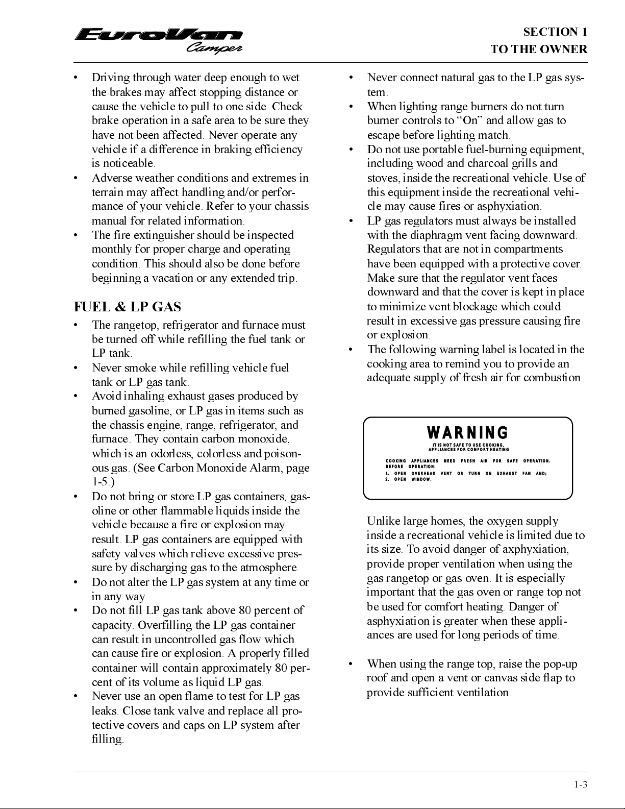
• T he fo llowing w ar ning label is loca t ed in the
cooking area to remind you to pro vide an
adequate supply of fresh air for combustion.
WARNING
IT IS NOT SAFE TO USE COOKING IT IS
APPLIANCES FOR COMFORT HEATING
COOKING APPLIANCES NEED FRESH AIR FOR SAFE OPERATION.
BEFORE OPERATION:
1. OPEN OVERHEAD VENT OR TURN ON EXHAUST FAN AND;
2. OPEN WINDOW.
Unlike large homes, the oxygen supply
inside a recreational vehicle is limited due to
its size. To avoid danger of axphyxiation,
provide proper ventilation when using the
gas rangetop or gas oven. It is especially
important that the gas oven or range top not
be used for comfort heating. Danger of
asphyxiation is greater when these appli-
ances are used for long periods of time.
• When using the range top, raise the pop- up
roof and open a vent or canvas side flap to
provide sufficient ventilation.
1-3
SECTION 1
TO THE OWNER
LP GAS LEAKS
T h e followin g labe l is loca ted in the v ehicle
near the range area. If you smell gas within the
vehicle, quickly and carefully perfor m the proce-
dures listed.
IF YOU SMELL GAS
1. E xtinguish any o p e n flames, p ilot
lights and all smoking materials.
2. Do not touch electrical switches.
3. Shut off the gas supply at the tank
valve(s) or gas supply connection.
4. Open doors and other ventilating
openings.
5. Leave the area until odor clears.
6. Have the gas system checked and
leakage source correct ed before
using again.
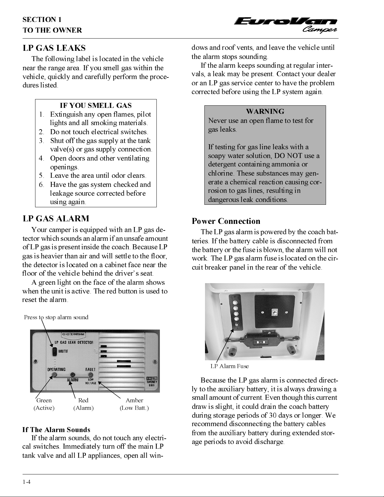
LP GAS ALARM
Your camper is equipped with an LP gas de-
tecto r which sounds an alarm if an unsafe amount
of LP gas is present inside the coach. Because LP
gas is heavier than air and will sett le to the floo r,
the detector is located on a cabinet face near the
floor of the vehicle behind the driver’s seat.
A green light on the face of the alarm shows
when the unit is ac tive. T he red button is used to
reset the alarm.
dows and roof vents, and leave the vehicle until
the alarm stops sounding.
If the alarm keeps sounding at regular inter-
vals, a leak may be present. Contact your dealer
or an LP gas service center to have the pro blem
corrected before using the LP system again.
WARNING
Never use an open flame to test for
gas leaks.
If testing for gas line leaks with a
soapy water solution, DO NOT use a
detergent containing ammonia or
chlorine. These substances may gen-
erate a chemical reaction causing cor-
rosion to gas lines, resulting in
dangerous leak conditions.
Power Connection
The LP gas alarm is po wered by the coach bat-
teries. If the battery cable is disconnected from
the battery or the fuse is blown, the alarm will not
work. The LP gas alarm fuse is located o n the cir-
cuit breaker panel in the rear of the vehicle.
Press to stop alarm sound
Green
(Active)
Red
(Alarm)
Amber
(Low Batt.)
If The Alarm Sounds
If the alarm sounds, do not t o uch any electri-
cal switches. Immediately turn off the main LP
tank valve and all LP appliances, open all win-
1-4
LP Alarm Fuse
Because the LP gas alarm is co nne cted d irect-
ly to t he auxiliary battery, it is always drawing a
small amount of cur rent. Even t hough t his current
draw is slight, it could drain the coach batter y
during storage periods of 30 days or longer. We
rec ommend d isconnect ing the battery cables
from the auxiliary battery during extended stor-
age periods to avoid discharge.
SECTION 1
TO THE OWNER
Further Information
See the manufacturer’s information entitled
“Your LP Gas Detector” in the Owner Informa-
tion binder for further instruct ions on nuisance
alarms and care and testing of the LP gas detec-
tor.
ELECTRICAL
·
Careless handling of electrical components
can be fatal. Never touch or use electrical
components or appliances while feet are bare,
while hands are wet , o r while st anding in wa-
ter or on wet ground.
·
Improper grounding of the vehicle can cause
personal injury. Do not plug the utilit y p o wer
cord into an outlet which is not gro unded and
do not adapt t he plug to connect to a recepta-
cle for which it is not designed.
·
Do not attach an e x ten sion cord to the utility
power cord.
·
Be sure that all electrical appliances to be
used contain 3-prong plugs for proper
grounding.
·
Avoid overloa d ing elec trical circuits. Re-
place fuses or circuit breakers with those of
the same size and amperage rat ing only. Nev-
er use a higher rated fuse or breaker.
·
Use caution when handling or working near
electrical storage batteries. Always remove
jewelry and wear protective clothing and eye
covering. Avoid creating sparks.
FORMALDEHYDE INFORMATION
WARNING
So me co mpo nents in this vehicle co n-
tain formaldehyde based adhesives
which may release formaldehyde
fumes into the air for an unknown
period of time until total dissipation
occurs. Individuals who are allergic
to formaldehyde gas fumes may
experience irritation to eyes, ears,
nose and throat. Reaction in infants
may be more severe. Although long
range effects are not well understood,
te sting to d ate has no t revealed an y
ser ious he alth e ffect s in humans a t t he
level of emission from these prod-
ucts.
NOTE: To aid in dissipation, ventilate the vehi-
cle by opening all windows and circulat-
ing the air with a fan.
CARBON MONOXIDE WARNING
WARNING
Avoid inhaling exhaust gases, as they
contain carbon monoxide, which is a
colorless, o do r less and poisonous gas.
LOADING
·
Store o r secur e a ll loo se it e ms inside t he mo-
tor home before traveling.
·
Neve r lo a d the vehicle in excess of the gr oss
vehicle weight rating or t he gro ss axle weight
rating for either axle.
If your suspect that exhaust fumes are entering
the passenger compartment, have the cause deter-
mined and corr ected as soon as possible. If you
must drive under these conditions, drive only
with ALL WINDOWS FULLY OPENED.
The be st pro tect io n a g ainst carbon mo noxide
entry into the vehicle body is a properly main-
ta ined eng ine e xha u st and vent ilat ion system. I t
is recommended that the exhaust system and
body be inspected by a qualifie d Vo l kswagen
service center.
·
Each time the vehicle is raised for an oil
change.
·
Whenever a change in the sound of the ex-
haust system is noticed.
1-5
SECTION 1
TO THE OWNER
·
Whenever the exhaust system, underbody or
rear of the vehicle is damaged.
To allow pro per o perat ion of the vehicle’s
ventilation system, keep front ventilation inlet
gr ill c lear of snow, leaves or other obstruct ions at
all times. DO NOT OCCUPY A PARKED VE-
HICLE WITH ENGINE RUNNING FOR AN
EXTENDED PERIOD.
Do not run engine in confined areas, such as a
garage, except to move vehicle in or out of area.
When vehicle is stopped in an UNCONFINED
area with the engine ru nning for any mor e t ha n a
short period, adjust heating or cooling system to
force outside air into the vehicle as follows:
1. Set fan to medium or high speed and vent
control to air.
2. O n ve hicles equipped with air conditioning,
set fan to medium or high speed and set co n-
trol to obtain maximum vent air.
Rear liftgate should be closed while driving to
avoid drawing dangerous exhaust gases into the
vehicle.
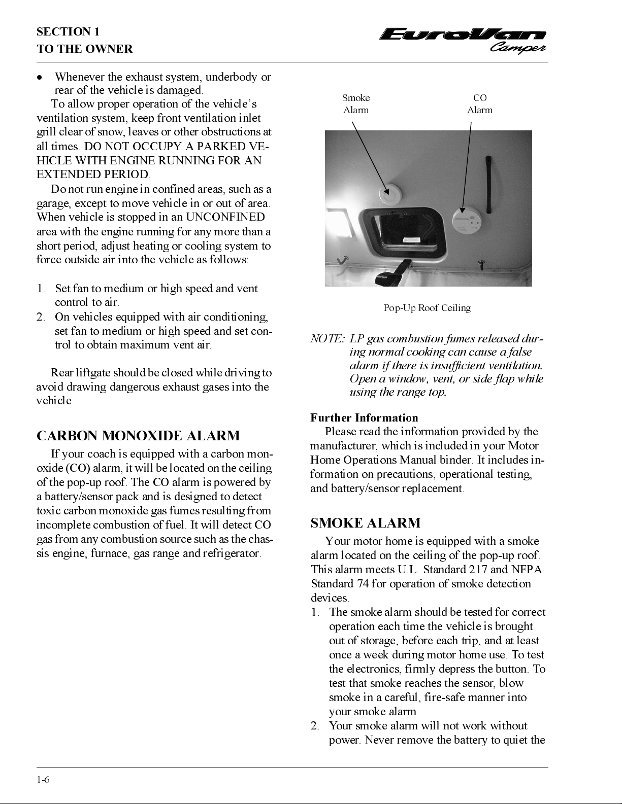
Smoke
Alarm
Pop-Up Roof Ceiling
CO
Alarm
NOTE: LP gas combustion fumes released dur-
ing normal cooking can cause a false
alarm if there is insufficient ventilation.
Open a window, vent, or side flap while
using the range top.
CARBON MONOXIDE ALARM
If your coach is equipped with a carbon mon-
oxide (CO) alarm, it will b e lo ca t ed on th e ce iling
of the pop-up roof. The CO alarm is powered by
a battery/sensor pack and is designed to det ect
toxic carbon monoxide gas fumes resulting from
inc o mp le te c ombu stio n o f fu e l. I t will d e tec t C O
gas from any combust ion source such as the chas-
sis engine, furnace, gas range and refrigerator.
Further Information
Please read the information provided by the
manufacturer, which is included in your Motor
Home Operations Manual binder. It includes in-
formation on precautions, operational testing,
and battery/sensor replacement.
SM OK E ALARM
Your motor home is equipped with a smoke
alarm loca ted on the c eiling of t h e pop-up ro o f.
This alarm meets U.L. Standard 217 and NFPA
Standard 74 for operation of smoke detection
devices.
1. The smoke alarm should be test ed for cor rect
operation each time the vehicle is brought
out of storage, before each trip, and at least
once a week during motor home use. To test
t h e ele ctron i c s, firmly depress the button. To
test that smoke reaches the sensor, blow
smoke in a careful, fire-safe manner into
your smoke alarm.
2. Your smoke alarm will not work without
power. Never remove t he battery to quiet the
1-6
SECTION 1
TO THE OWNER
alarm. When your smoke alarm “beeps”
about once a minute the battery is weak.
Install a new battery immediat e ly . Be sure to
use only batteries specified in manual or o n
unit. Test unit after installing a new battery.
3. Clean and vacuum the openings on your
smoke alarm once a month.
4. Do not o pen the smoke alarm or tr y to repair
it. For replacement information see warranty
in Owner’s Manual.
5. Smo k e a la r ms ha v e techn ic a l limit a tions an d
may not respo nd in all situations. FIRE PRE-
VENTION is your best safeguard.
Further Information
Please read the information provided by the
manufacturer, which is included in your Motor
Home Operations Manual binder. It includes
information on precautions, operational testing,
and bat t ery/sensor replacement.
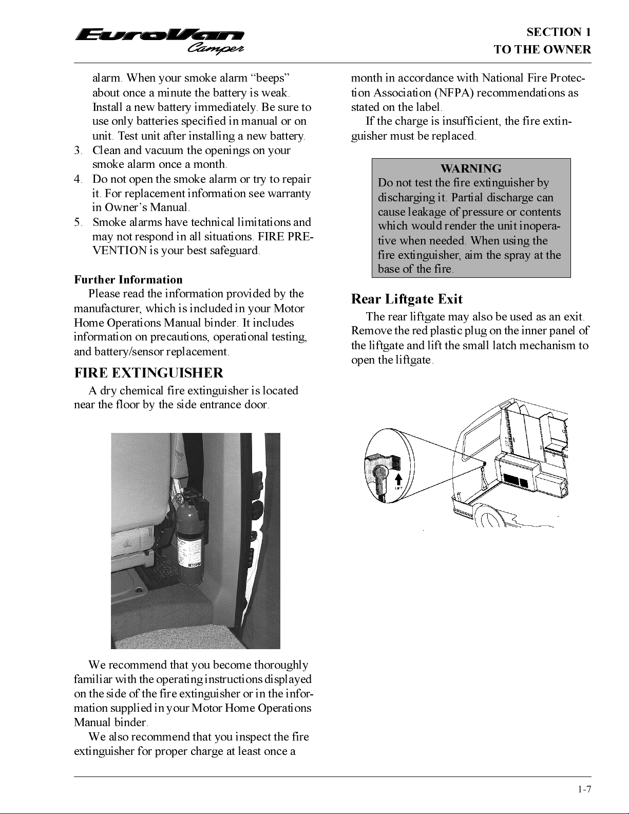
FIRE EXTINGUISHER
A dry chemical fire extinguisher is located
near the floor by the side entrance door.
month in accordance with National Fire Protec-
tion Association (NFPA) recommendations as
stated on the label.
If the charge is insufficient, the fire extin-
guisher must be replaced.
WARNING
Do not test t he fire extinguisher by
discharging it. Partial discharge can
cause leakage of pressure or contents
which would render the unit inopera-
tive when needed. When using the
fire extinguisher, aim the spray at the
base of t h e fire.
Rear Liftgate Exit
The rear liftgate may also be used as an exit.
Remove the red plastic plug on the inner panel of
the liftg a te and lift t he small latc h mec hanism t o
op e n the lift g ate.
We recommend that you become thoroughly
familiar with the oper ating inst ructions displayed
on the side of t he fire extinguisher or in the infor-
mation supplied in your Motor Home Operations
Manual binder.
We also recommend that you inspect the fire
extinguisher for proper charge at least once a
1-7

 Loading...