


Service Training
Self-study programme 328
The 2004 Caddy
S328_001
The 2004 Caddy is built on the same platform as the 2004 Golf. Compared with the previous
model based on the Polo platform, we have improved the technology and comfort considerably.
The 2004 Caddy will thus take a leading position among its rivals.
Unlike its predecessor, the 2004 Caddy now comes in three different versions.
The Caddy Van, Caddy Shuttle and Caddy Life cover a wide range of needs.
In addition to, increased payload, more space and also improved functionality, the 2004 Caddy
has a boarder engine range that now also offers greater performance.
Furthermore no shortcuts have been taken in crash safety.
The self-study programme shows the design and
function of new developments.
The contents will not be updated.
2
NEW
For current testing, adjustment and repair instructions,
refer to the relevant service literature.
Important
Note

Contents
In brief . . . . . . . . . . . . . . . . . . . . . . . . . . . . . . . . . . . . . . . . . . . . . . 4
Body . . . . . . . . . . . . . . . . . . . . . . . . . . . . . . . . . . . . . . . . . . . . . . . 14
Occupant protection . . . . . . . . . . . . . . . . . . . . . . . . . . . . . . . . . . 28
Engines . . . . . . . . . . . . . . . . . . . . . . . . . . . . . . . . . . . . . . . . . . . . . 30
Transmission . . . . . . . . . . . . . . . . . . . . . . . . . . . . . . . . . . . . . . . . . 34
Chassis . . . . . . . . . . . . . . . . . . . . . . . . . . . . . . . . . . . . . . . . . . . . . 36
Electrical system. . . . . . . . . . . . . . . . . . . . . . . . . . . . . . . . . . . . . . 48
Heating and air-conditioning . . . . . . . . . . . . . . . . . . . . . . . . . . . 62
Radio, telephone and navigation. . . . . . . . . . . . . . . . . . . . . . . . 66
Service . . . . . . . . . . . . . . . . . . . . . . . . . . . . . . . . . . . . . . . . . . . . . 70
3
In Brief
The 2004 Caddy
Where is the 2004 Caddy built?
In 1993, a joint venture was set-up between the
Polish car manufacturer FSR
(in Polish = Fabryka Samochodów
Rolniczych,
English = Factory for Agricultural
Automobiles)
and Volkswagen Group.
Volkswagen Poznan GmbH has been a
100-percent subsidiary of Volkswagen
Commercial Vehicles since 1997.
The original business concept behind Volkswagen Poznan GmbH was to assemble light commercial
vehicles from kits. Kits from the different Volkswagen Group brands were delivered to Poznan for
complete assembly. Operations were expanded constantly over the next years. Around 3,400 members
of staff currently work at the plant.
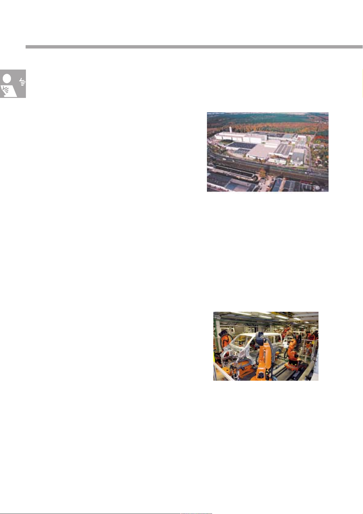
The plant in Poznan
S328_002
Major investments include the set-up of a new
paint shop, a new body plant and new assembly
lines for the 2004 Transporter and the 2004
Caddy.
The result is a complete automobile plant with its
own logistics services, quality assurance
department and all associated areas. Among
others, the latest laser welding and soldering
techniques are being used for the new models.
With the launch of the 2004 Transporter, the plant now has its very own product for the first time. All
2004 Transporters with open superstructures are produced in Poznan. The 2004 Transporter Kombi also
rolls off the assembly line in Poznan.
Now Poznan has another product of its own - the 2004 Caddy.
Paint shop
S328_004
4

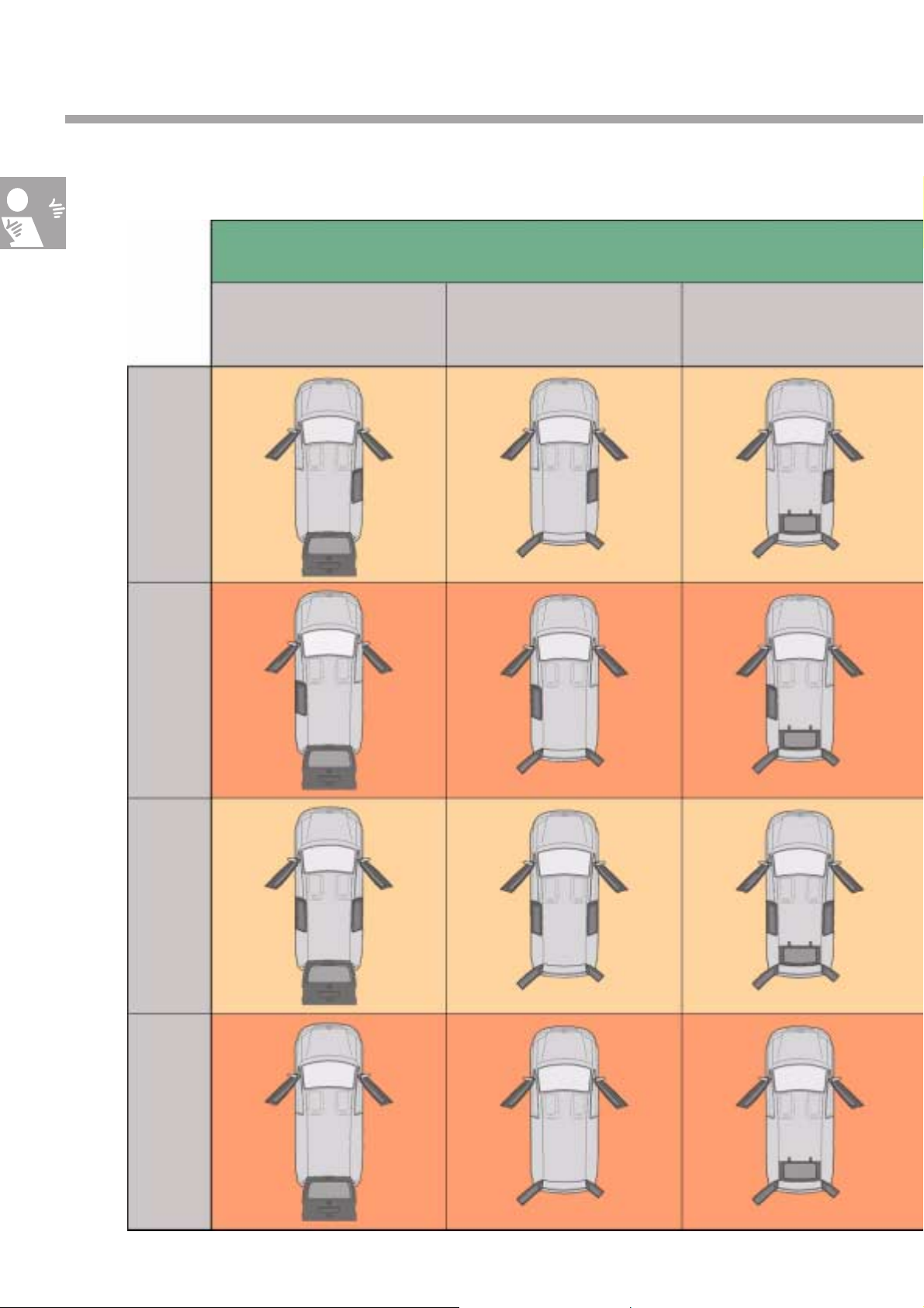
The Competitors
The diagram shows the field of competitors facing the 2004 Caddy. Only one version of each vehicle is
shown to represent the respective range.
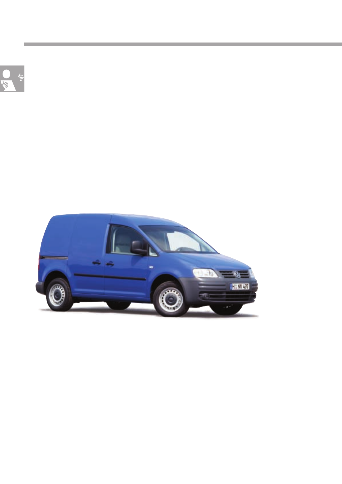
2004 Caddy Van
S328_096
Fiat Doblò
Opel Combo
Immediate rivals
Competition
Renault Kangoo
Ford Tourneo Connect
Citroën Berlingo
Mercedes Vaneo
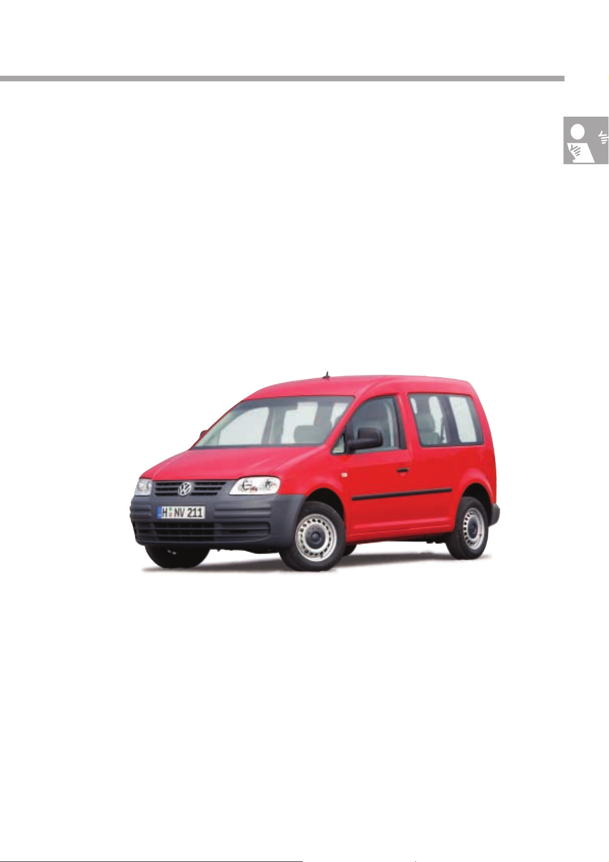
2004 Caddy Shuttle/Life
S328_162
S328_097
5
In Brief
Technical highlights in the 2004 Caddy
The 2004 Caddy is setting new standards with the Caddy Van, Caddy Shuttle and Caddy Life versions.
It features a modern design with smooth outer surfaces all-round.
Here is an overview of the highlights:
Caddy Van
• Payload up to 750 kg
• Towing up to 1,500 kg
• Loading capacity up to 3.2 m
• Sliding door on right and left (optional),
Sliding door opens wide to 700 mm
3
• Clear glass headlamps with H1/H7 bulbs
• Electromechanical power
steering
• Navigation/preparation
for telephone (optional)
S328_096
• Rear axle with leaf springs
• ABS - MK70 system (Conti Teves)
• Generous storage compartments in the
doors and cab roof ceiling of driver’s cab
6
• Crash-optimised pedals and
crash-optimised steering
column
• Airbag system with
front side airbags
• Glazed load compartment,
same as Shuttle (optional)
Caddy Shuttle/Caddy Life
The Shuttle version of the 2004 Caddy, offering further highlights compared with the Caddy Van, comes
in 2 versions:
– Caddy Shuttle is the “Basic” version and
– Caddy Life is the “Comfort” version
• Up to 7 seats in the
Caddy Shuttle/Caddy Life
• Rear vent wings (optional)
on Caddy Shuttle/Caddy Life
S328_097
• ESP (optional)
MK60 system (Conti Teves)
• Tipping 1st seat row in passenger
compartment on Caddy Shuttle/Caddy Life
• Generous storage facilities in
Caddy Life passenger compartment
• Removable and locking tow bar
on Caddy Shuttle/Caddy Life
• 2nd seat row in passenger compartment (optional) in form of folding and
removable double bench
• Sliding windows in
sliding doors
7
In Brief
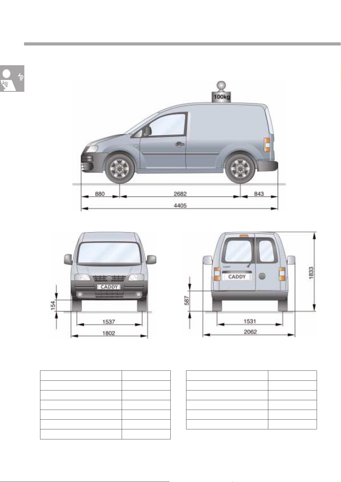
Technical data
Caddy Van
S328_005
S328_094S328_006
Dimensions
Length 4,405 mm
Length with tow bar 4,505 mm
Width 1,802 mm
Width with mirrors 2,062 mm
Height 1,833 mm
Overhang length at front 880 mm
Overhang length at rear 843 mm
Height of load sill 587 mm
Ground clearance 154 mm
Wheelbase 2,682 mm
Track width at front 1,537 mm
Track width at rear 1,531 mm
Tank capacity 60 l
8
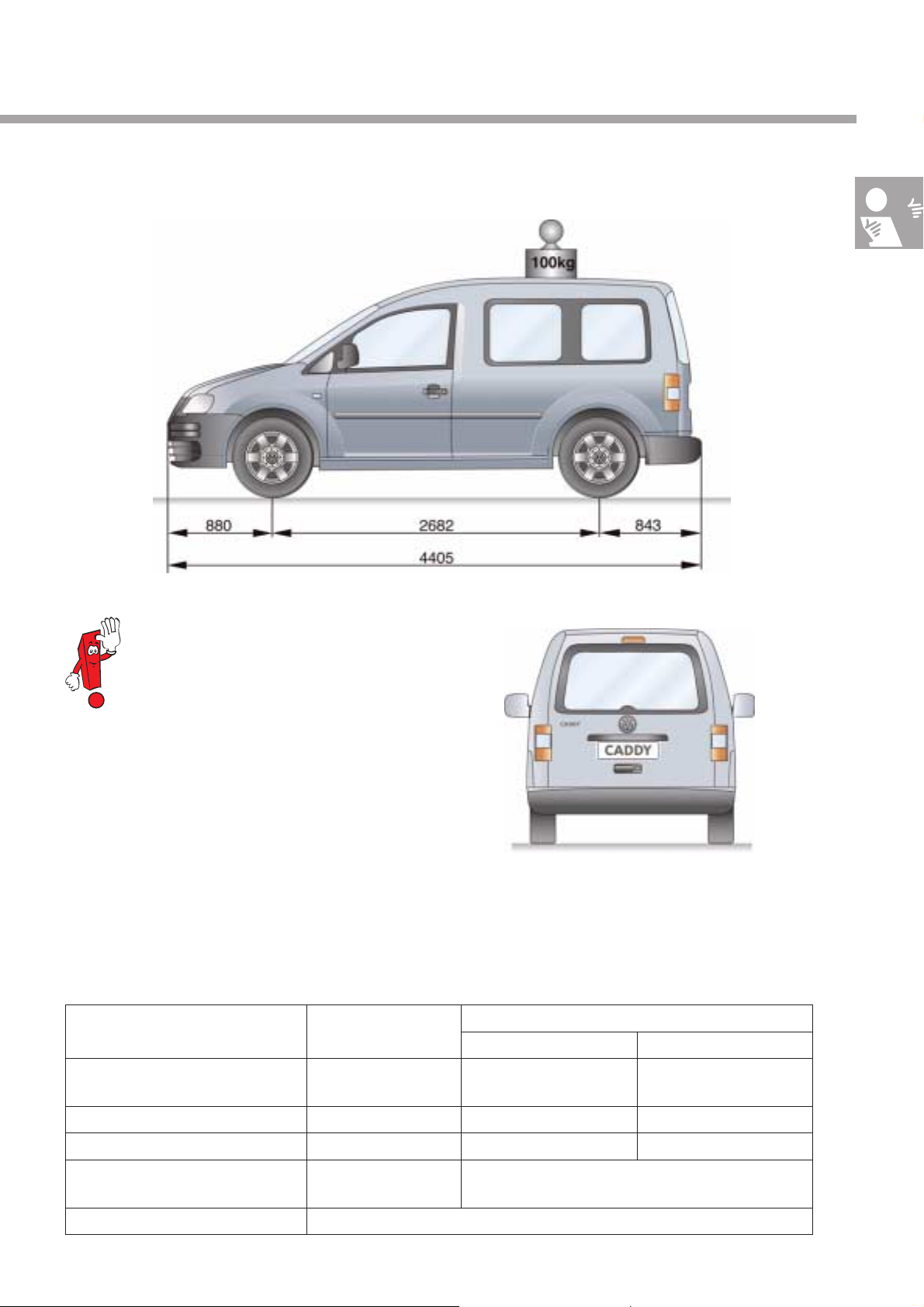
Caddy Shuttle/Caddy Life
The Caddy Van, Caddy Shuttle and
Caddy Life look the same from the
front. The outside dimensions of the
different Caddy versions are the same.
They only differ in equipment and
weight.
S328_095
S328_007
Weight
Caddy Van Caddy Shuttle/Caddy Life
5-seater 7-seater
Curb weight including driver* 1,400 – 1,481 kg 1,476–1,560 kg (Shuttle)
1,521 – 1,605 kg (Life)
Maximum weight* 2,150 – 2,235 kg 2,000 – 2,124 kg 2,165 – 2,250 kg
Braked towing capacity* 1,200 – 1,500 kg 1,200 – 1,500 kg 1,035 – 1,350 kg
Load without driver* up to 750 kg 503 - 653 kg (Shuttle)
479 - 608 kg (Life)
Roof load 100 kg
* Depending on engine and equipment
1,513-1,597 kg (Shuttle)
1,558 –1,642 kg (Life)
9
In Brief
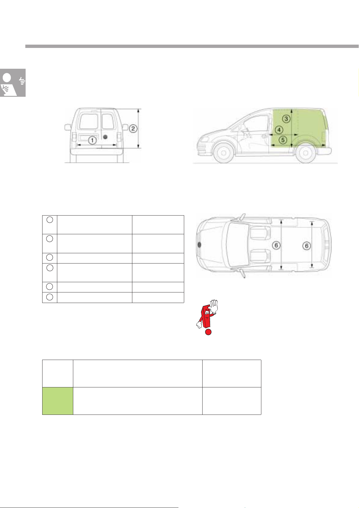
Interior dimensions
Caddy Van
S328_008b
Load compartment dimensions
1 Opening width -
rear door/tailgate
2 Opening height -
rear door/tailgate
3 Loading height up to 1,257 mm
4 Opening width -
sliding door
5 Loading length up to 1,781 mm
6 Loading width 1,172 to 1,558 mm
1,181 mm
1,116 mm
700 mm
Load compartment – Volume
S328_008a
S328_009
The pictures show the Caddy Van with
wing doors. A tailgate is also available
as an option.
10
Colour Volumes
Name Volumes
Load compartment volumes up to 3,200 l
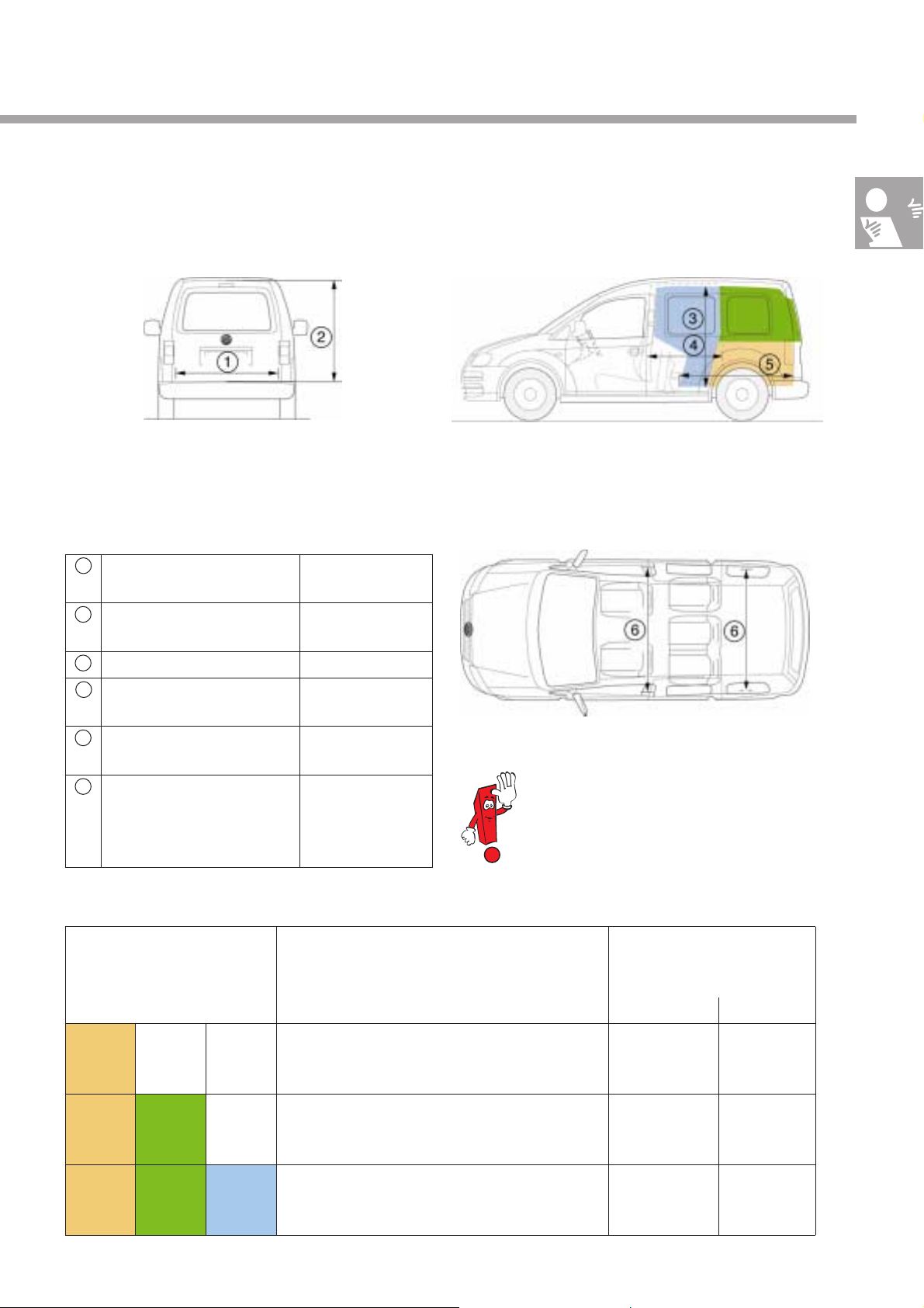
Caddy Shuttle/Caddy Life
S328_010b
Luggage compartment -dimensions
1 Opening width -
rear door/tailgate
2 Opening height -
rear door/tailgate
3 Loading height up to 1,238 mm
4 Opening width -
sliding door
5 Luggage compartment
length
6 Luggage compartment
width (Shuttle)
Luggage compartment
width (Life)
1,181 mm
1,116 mm
700 mm
up to 1,354 mm
1,170 to 1,340 mm
1,120 to 1,340 mm
S328_010a
S328_011
The pictures show the Caddy Shuttle
with tailgate. It can also be equipped
with optional wing doors.
Luggage compartment – volume
Colour partial volume
Name Volume
Volume, closed luggage compartment,
behind 1st seat row in passenger compartment
Volume, open luggage compartment,
behind 1st seat row in passenger compartment
Volume, open luggage compartment,
behind front seats with tipped 1st seat row
Sum of partial volume
Caddy Shuttle Caddy Life
up to 626 l up to 560 l
up to 1,266 l up to 1,200 l
up to 2,305 l up to 2,239 l
11
In Brief
Overview of doors
Caddy Van
… with tailgate … with rear
Right-hand sliding doorLeft-hand sliding doorSliding doors on both sidesWithout sliding door
wing doors
… with rear
wing doors and
“ladder flap”
12
S328_012

Caddy Shuttle/Caddy Life
… with tailgate … with rear
wing doors
… with rear
wing doors and
“ladder flap”
The 2004 Caddy comes in a wide range of
versions. The variable equipment with sliding
doors, rear wing doors, tailgates or a ladder
flap.
S328_013
The picture shows the complete Caddy
range.
The assignment of left-hand and righthand drive vehicles can be found in the
current sales literature.
The ladder flap will be available later
on.
13
Body
Body in white
A sturdy body in white has a decisive influence on the stability and thus also on the driving safety of a
vehicle. This particularly important for vehicles that are mainly used as fast commercial vehicles.
The driving comfort also benefits from a good body design. That is a plus for the Caddy Shuttle and the
Caddy Life when used as a family and leisure vehicle.
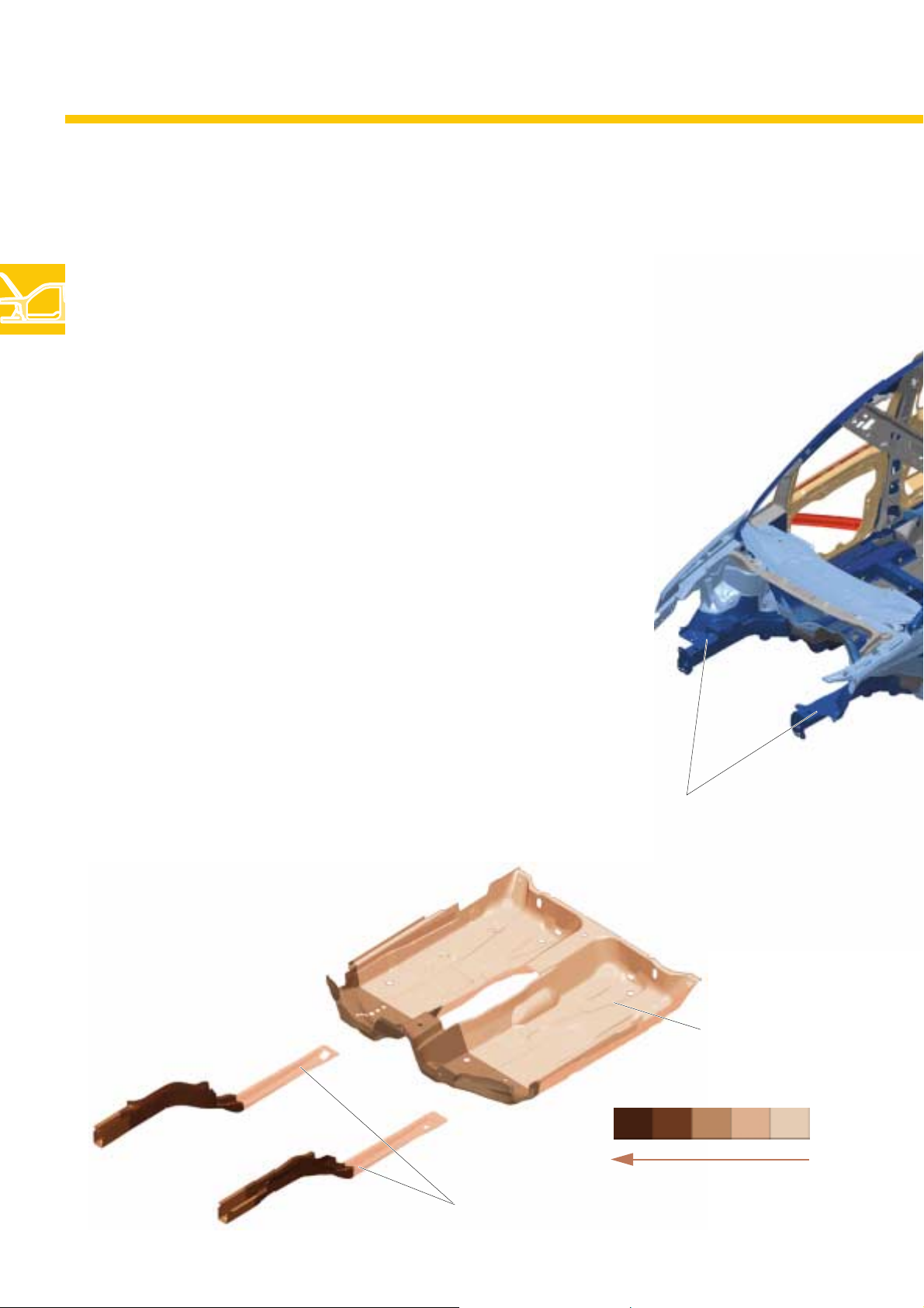
The 2004 Caddy has a torsionally stiff and low
weight two-shell body structure (inside/outside
body shell). The following structural features can
be distinguished in terms of function:
– Floor pan with frame structure,
with tailored blanks at front (different sheet
thicknesses, welded before shaping)
– inner body shell,
with reinforcement elements,
– outer body shell,
single-piece side section
– Roof reinforcements
– Use of different sheet qualities depending on
the loading of the respective body areas
– Reinforcement and impact elements for
improved occupant protection in the front
doors
Floor pan - front
with tailored blanks
Longitudinal member - front
S328_168
14
Floor - front
increasing sheet thickness
Longitudinal member - front
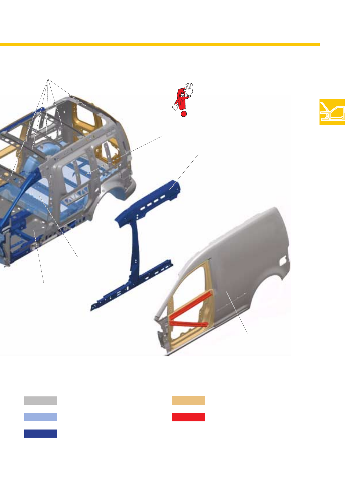
Roof reinforcements
The pictures show the body
in white of the Caddy Van.
Cross member
Reinforcing element
Floor panel - rear
Floor panel - front
Normal-strength sheet
Higher strength sheets
S328_014
Side section (one-piece)
Mounted partsSheet qualities
Doors
Side impact elements
High-strength sheets
15
Body
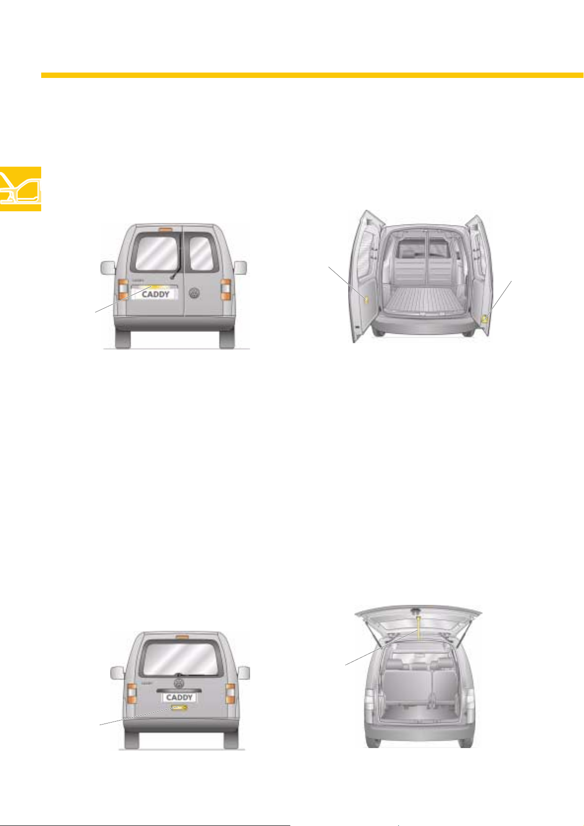
Wing doors
The Van version of the 2004 Caddy comes with glazed wing doors split in the ratio 2/3 to 1/3.
The windows in the wing doors can be covered with an optional dark opaque film. The Caddy Shuttle/
Caddy Life can be optionally fitted with the wing doors.
Inside handle
Outside handle
S328_087
Locking lever
S328_088
The left-hand wing door needs to be opened first. The outside handle on the left-hand door is integrated
in the number plate light fitting. The locking level built into the bottom of the right-hand door can then be
used to open the right-hand wing door. Wing doors lock at a 90° angle when opened. If the door
latches are detached, the wing doors will open to approx. 170° due to a stop in the hinge.
Tailgate
The Caddy Shuttle and Caddy Life come with a tailgate with rear window as standard. The Caddy Van
can also be fitted with a tailgate. The tailgate can be opened with an outside handle. A draw loop is
provided to help pull it down.
Draw loop
16
Outside
handle
S328_089
S328_090
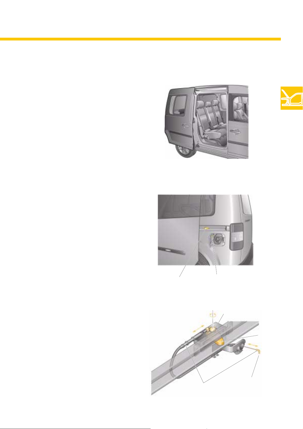
Sliding door
The 2004 Caddy is equipped with a sliding door
reaching up to the roof on the passenger side.
The drivers side can also be fitted with an
optional sliding door.
The sliding door opens to a maximum width of
70 cm.
Only the Caddy Van with a glazed load
compartment can be equipped with a sliding
door.
The Caddy Shuttle and Caddy Life have sliding
doors a with windows.
S328_092
Protection of the tank filler flap
The tank filler flap is located on the driver’s side
just in front of the D-pillar. To ensure that it is not
damaged when the door is slid backwards, the
2004 Caddy has a locking unit when equipped
with a sliding door on the left-hand side.
Function
When the tank filler flap is open, a Bowden
cable attached to the tank filler flap activates a
rotating bolt in the locking unit. The blocking
latch connected to the rotating bolt is then
moved outwards so that the sliding door hits it
and cannot be pushed back any further.
Blocking latch
Blocking unit
Bowden cable
on tank filler flap
Bowden cable
S328_103
Rotating bolt
Blocking latch
S328_132
Connect to
tank filler flap
17

Body
Window
Sliding window
The version of the Caddy Van with glazed load
compartment can be optionally fitted with a
sliding window in the sliding door.
The Caddy Shuttle can also be equipped with an
optional sliding window in the sliding door.
The Caddy Life comes with the sliding window as
standard.
S328_129
Vent windows
Optional manual vent windows are also
available for the Caddy Shuttle and Caddy Life.
Both sides will be equipped with vent windows
when this option is chosen.
S328_130
18
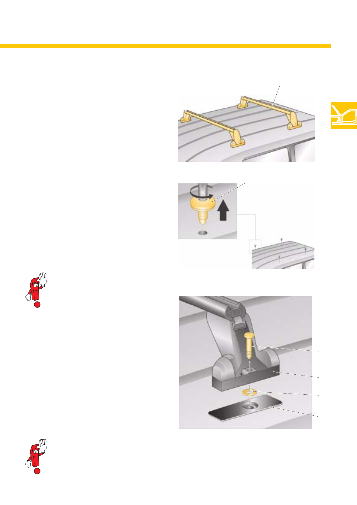
Roof rack
A system with a bolt-on base carrier is used for
the roof rack on the 2004 Caddy.
There are special accessories allowing you to
attach a roof box, bicycles, skis, surfboards or
boats on the base carrier.
The bolt-on base carrier guarantees a high level
of stability.
Base carrier
S328_017
4 screws with rubber seals are fitted on the
vehicle roof. These screws need to be removed
together with the seal to fit the base carrier.
The sealing screws should be kept and
fitted again when the base carrier is
removed to seal the roof.
The base carrier is secured with the supplied
screws and seals.
Screw with
seal
S328_104
Screw
The seals prevent water leaking into the
body.
Refer to the operating manual for information on fitting the base carrier.
Foot
Seal
Protective
film
S328_105
19
Body
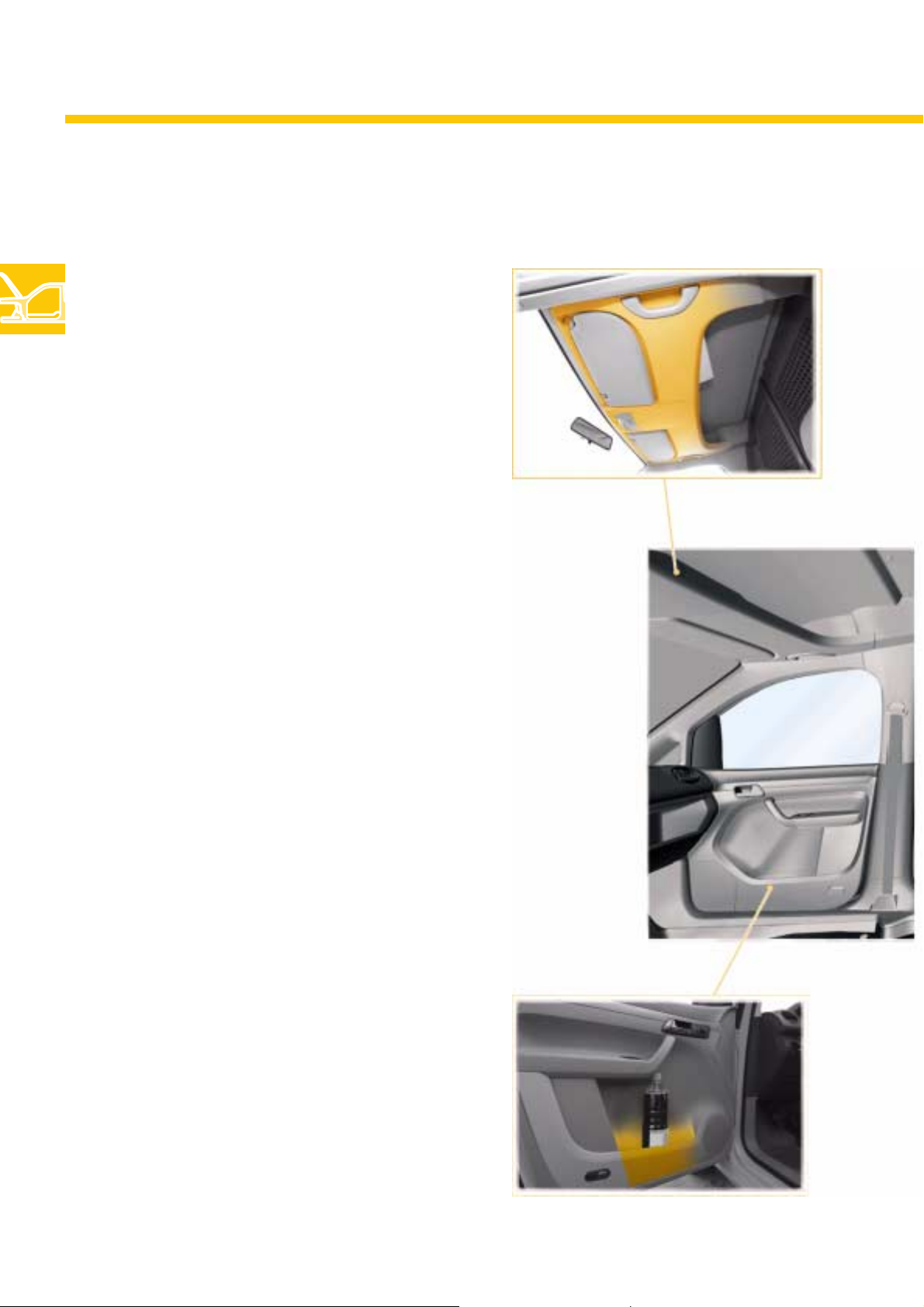
Interior concept
Caddy Van
The equipment provided in the Caddy Van is
mainly directed at commercial vehicle
applications.
Storage compartments in the side doors and an
overhead compartment have been provided for
the driver and front passenger
– in addition to the storage bins in the
– dash panel and centre console.
The generous overhead storage is particularly
useful. It can even hold A4 binders thanks to the
width of 1000 mm, depth of 400 mm and height
of up to 250 mm.
Overhead storage
The cargo is safely secured by the lashing rings
and the bulkhead between the cab and the load
compartment. The bottom half of the bulkhead is
made from a plastic surface and the top from a
plastic grille.
The floor of the load compartment can also be
covered with an optional rubber mat.
The side panels underneath the windows in the
load compartment are protected with noncoated hardboard. There are no additional
storage compartments here.
20
Storage in driver’s door
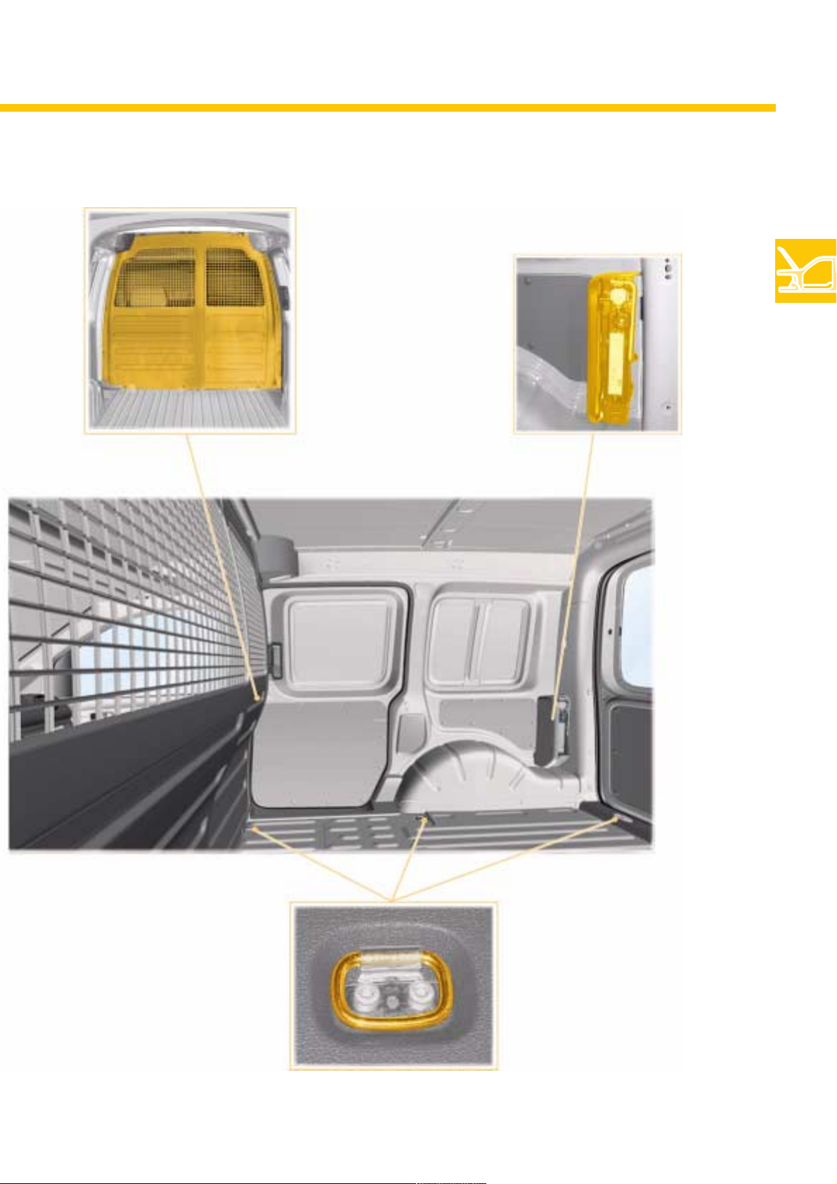
Bulkhead
Jack and tool set,
mounted without cover
Lashing rings on floor
S328_151
21
Body
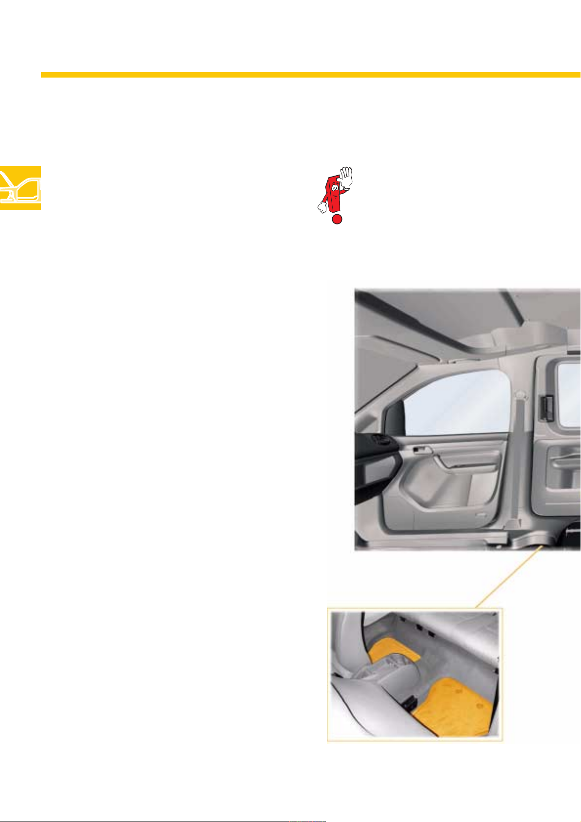
Caddy Shuttle/Caddy Life
The Shuttle version of the 2004 Caddy comes in
the equipment derivatives
– Caddy Shuttle as the “Basic” version and
– Caddy Life as the “Comfort” version.
In the Caddy Shuttle, the floor of the passenger
compartment is fitted with carpet (Dilours) as
standard. Four lashing rings on the floor allow
safe anchoring of loads.
The side panels of the passenger compartment
are made from varnished hardboard. They do
not have storage compartments. The ceiling is
is also lined with varnished hardboard.
There are two storage compartments with
removable lids in the footwell in front of the first
row of seats in the passenger compartment.
The jack and tool set are mounted on the side
wall without a cover.
The picture shows a Caddy Life.
The Caddy Life has additional features
compared with the Caddy Shuttle. The side
panels are moulded sections with integrated
storage bins.
Attachment rings are mounted above the
windows for an optional net partition.
A further option is storage nets with hooks for
hanging items. The Caddy Life comes with a
luggage area cover as standard (not shown
here).
The jack and tool set are stowed away behind a
cover in the side panelling.
22
Compartment in floor

Hooks for net partition and storage net
Jack and tool set
behind panel
Sliding door storage
S328_152
Storage between C and D-pillar
23

Body
Dash panel
The 2004 Caddy has an all-new dash panel. There are two versions that mainly differ in the centre
console equipment.
Centre console type with
– open storage
– cup holders
– ashtray in passenger compartment
Fitted as standard in the Caddy Van and
Caddy Shuttle.
Centre console
(Caddy Shuttle/Life)
Centre console type with
– Compartment for a CD changer under the
armrest lid
– Air-conditioning vents
– fold-out cup holder
– 12 V socket
This centre console is longer and comes as
standard in the Caddy Life and is an option in
the Caddy Shuttle.
Cup holder
Armrest
with storage
compartment
Socket 12 V
24
Storage
Centre console
(Caddy Van/Shuttle)
Further differences between the console
types are the materials used and the
resulting material feel.
Cup holder
Storage
Ashtray
2 x 2 cup holders

Left-hand storage compartment on
top of dash panel
(Caddy Van and Caddy Shuttle)
Right-hand storage compartment on
top of dash panel -without lid
Left-hand storage compartment on
top of dash panel - with lid and
document holder (Caddy Life)
Ashtray and cigarette
lighter
S328_153
Storage compartment on
passenger side
containing key switch for front
passenger airbag
Key switch
for front passenger airbag
25

Body
Seats
The driver and front passenger seats in the
2004 Caddy are individual seats. The first row of
seats in the Caddy Shuttle/Life is a 3-seat bench
split 1/3-2/3. An optional double bench can be
fitted in the second row.
Head restraints
Handle for
folding seat
Side airbag
Adjustment of
backrest tilt
Height adjustment
S328_030
Seats (example Caddy - 7-seater)
Individual seats
driver/front
passenger
1st seat row
in passenger
compartment
The adjustment of the seats is described
in detail in the operating manual.
The picture shows a vehicle fitted with
all available seats (Shuttle/Life version
with drawer).
The drawer is always combined with the
height adjuster in the Caddy Shuttle/
Life and vice versa.
2nd seat row
in passenger
compartment
S328_093
Longitudinal
adjustment
Features on driver’s seat and front passenger seat Caddy
Longitudinal adjustment
Adjustable backrest tilt
Head restraint height adjustable
Side airbag (optional)
Individually adjusted heated seats (optional)
Storage under seat (optional)
Head restraint height and tilt adjustable
Drawer under seat (optional)
Seat height adjustable
Backrest folds forward (when there is only one sliding door, always
on the opposite side of the vehicle)
Drawer/storage
Va n
Caddy
Shuttle
Caddy
Life
26

Seats in passenger compartment
The three-seat bench in the first seat row of the
passenger compartment is split into a 1/3 seat
and a 2/3 seat. The bench is permanently
screwed to the floor and cannot be removed.
The backrests of each seat section can be folded
forward separately and lock into a horizontal
position. If the seat section fastenings on the
vehicle floor are unlocked, you can fold the
folded seats forwards again, i.e. tip them.
This can be done without removing the head
restraints. Gas-filled springs make tipping the
seats easy.
The seat sections can be secured in position with
folding struts so that they do not move on the
road.
1st row of seats in passenger compartment individual seat tipped
Loop
for releasing
backrest
Floor latch
S328_148
1st row of seats in passenger compartment tipped completely
2nd row of seats in passenger compartment folded
Loop for
folding
Loop for unlocking
on vehicle floor
Strut
S328_150
Screw fastening
Gas-filled
struts
The double seat bench for the second row of
seats is fixed to the floor with 4 bolts.
The top left loop is used to unlock the backrest,
which can then be folded forward.
Pulling the two bottom loops releases the
fastening of the seat bench to the vehicle floor so
you can take the seat out from the rear of the
vehicle.
Strut
S328_032
27

Occupant protection
Occupant protection
The 2004 Caddy is equipped with the proven occupant protection systems, the airbag system,
the belt system and a child restraint system (Isofix) depending on the vehicle version.
The complete airbag system includes:
– Driver airbag
– Front passenger airbag – single-stage*
– Front side airbags*
* Optional for Caddy Van
The belt system includes:
– Three-point safety belts with belt tensioners
and belt pressure limits on the driver’s and
front passenger seat
– Three-point safety belts without belt
tensioners for the rear seat rows. The centre
seat on the first row of seats has a retractor
built into the top of the backrest to roll up the
belt.
The Isofix child restraint system is integrated on
the two outside seats of the first seat row.
Side airbag for
front passenger
Front airbag for
front passenger
Front passenger
airbag
module
28
S328_036
A key switch in the glove compartment allows
you to disable the front passenger airbag in the
2004 Caddy.
Airbag control unit
with crash sensor for
front airbags
Driver
airbag
module

The picture shows the Caddy Life.
Front passenger
side airbag
module
Three-point seat belt,
integrated in seat
Front airbag
for driver
Side airbag crash sensor,
in cab under driver’s/front
passenger’s seat
Side airbag
for driver
S328_037
Three-point seat belt with
rack and pinion belt
tensioner, fixed to body
Driver
side airbag
module
29

Engines
1.4l/55 kW petrol engine
The 1.4l/55 kW petrol engine has already proven
itself in the Golf and now features in the
2004 Caddy.
Technical features
– 4-valve technology
– 2 hollow overhead camshafts
– Reduced-weight crankshaft
– Lightweight piston
– ME 7.5.10 engine management
– Aluminium sump with oil level sensor
– Electronic power control with contact-free
sensors
– Exhaust gas recirculation with electrical valve
– Single-spark ignition coils
– Non-return fuel system
– Air filter integrated in the engine cover
S328_038
Engine code BCA
Type 4-cylinder in-line engine
Displacement 1,390 cm
Bore 76.5 mm
Stroke 75.6 mm
Valves per cylinder 4
Compression ratio 10.5 : 1
Maximum output 55 kW at
5,000 rpm
Maximum torque 126 Nm at
3,800 rpm
Engine management ME 7.5.10
Fuel Super unleaded RON 95
(normal unleaded at
RON 91 with reduction in
performance)
Exhaust gas
treatment
Exhaust gas recirculation,
starter/main catalytic
converter, Lambda
control
3
Torque and power diagramTechnical data
Torque (Nm)
Power (kW)
S328_039
Engine speed (rpm)
30
Emissions standard EU4/EOBD

1.6l/75 kW petrol engine
The 1.6l/75 kW petrol engine has already been
used in the Golf and Touran and is now being
mounted in the 2004 Caddy.
Technical features
– An assembled camshaft
– Roller rocker arm
– SIMOS 7.1 engine management
– Aluminium sump with oil level sensor
– Electronic power control
– Exhaust gas recirculation with electrical valve
– Electronic distributorless ignition
– Non-return fuel system
– Secondary air system
S328_040
Engine code BGU
Type 4-cylinder in-line engine
Displacement 1,595 cm
Bore 81.0 mm
Stroke 77.4 mm
Valves per cylinder 2
Compression ratio 10.3 : 1
Maximum output 75 kW at
5,600 rpm
Maximum torque 148 Nm at
3,800 rpm
Engine management Simos 7.1
Fuel Super unleaded RON 95
(normal unleaded at
RON 91 with reduction in
performance)
Exhaust gas
treatment
Exhaust gas recirculation,
catalytic converter,
Lambda control
3
Torque and power diagramTechnical data
Torque (Nm)
Engine speed (rpm)
Power (kW)
S328_041
Emissions standard EU4/EOBD
31

Engines
1.9l/77 kW TDI engine
The 1.9l/77 kW TDI engine has already proven
itself in the Golf and now features in the
2004 Caddy.
Technical features
– Diesel engine with exhaust-gas turbocharger
– Unit injector system
– Overhead camshaft
– EDC 16 engine management
– Electronic power control with contact-free
sensors
– Exhaust gas recirculation
– Electrical intake manifold flap
S328_044
Technical data Torque and power diagram
Engine code BJB
Type 4-cylinder in-line engine
Displacement 1,896 cm
Bore 79.5 mm
Stroke 95.5 mm
Valves per cylinder 2
Compression ratio 19 : 1
Maximum output 77 kW at
4,000 rpm
Maximum torque 250 Nm at
1,900 rpm
Engine management EDC 16
Fuel Diesel min. 51 CN
Exhaust gas treatment Exhaust gas recirculation
and oxidation catalytic
converter
3
Torque (Nm)
Engine speed (rpm)
Power (kW)
S328_045
32
Emissions standard EU3

2.0l/51 kW SDI engine
The 2.0l/51 kW SDI engine with unit injector
technology is a further development of the 1.9l/
74 kW TDI engine used in the Touran.
Technical features
– Naturally aspirated diesel engine
– Unit injector system
– Overhead camshaft
– EDC 16 engine management
– Electronic power control with contact-free
sensors
– Exhaust gas recirculation
– Electrical intake manifold flap
S328_042
Engine code BDJ
Type 4-cylinder in-line engine
Displacement 1,968 cm
Bore 81.0 mm
Stroke 95.5 mm
Valves per cylinder 2
Compression ratio 19 : 1
Maximum output 51 kW at
4,200 rpm
Maximum torque 140 Nm at
2,200 – 2,400 rpm
Engine management EDC 16
Fuel Diesel min. 51 CN
Exhaust gas treatment Exhaust gas recirculation
and oxidation catalytic
converter
3
Torque and power diagramTechnical data
Torque (Nm)
Engine speed (rpm)
Power (kW)
S328_043
Emissions standard EU3
33

Transmission
Gearbox
Two mechanical manual gearboxes conceived for transverse installation feature in the 2004 Caddy.
The gearboxes are based on the proven group manual gearboxes. They have been further developed
with the following changes.
Changes:
– Shaft spacing increased
– Axle drive reinforced
– Gearbox and clutch housing adapted
– Without sender for driving speed
5-speed gearbox 0AH
The gearbox is a further development of the 02T
manual gearbox, as already used in the Polo, for
example.
The gearbox has 5 gears and can transmit
torques of up to 200 Nm.
It is used with the petrol engines and the SDI
engine.
5-speed gearbox 0A4
S328_047S328_133
The gearbox is a further development of the 02J
manual gearbox. The construction has been
specially reinforced for the greater torque to be
transferred and is already used in the 2004
Golf.
The gearbox has 5 gears and can transmit
torques of up to 250 Nm. It is used with the
TDI engine.
34
Both gearboxes do not have a sender wheel for the speed.
The speed signal is transmitted by the ABS system.

Engine-gearbox combinations
Engine 5-speed
manual gearbox
0AH
1.4l/55 kW
petrol engine
BCA
1.6l/75 kW
petrol engine
BGU
5-speed
manual gearbox
0A4
1.9l/77 kW
TDI engine
BJB
2.0l/51 kW
SDI engine
BDJ
35

Chassis
Front axle
The 2004 Caddy has an optimised McPherson front axle with lower wishbones and MacPherson struts.
The axle is basically the same as the front axle on the 2004 Golf and provides optimum comfort with
good driving dynamics. The standing height has been increased especially for use in the 2004 Caddy.
Technical features are:
– Aluminium assembly carrier
– Wishbones
– Decoupled spring and damper connection by
rubber/metal bearings for the struts
– 3rd generation wheel bearings
– Active speed sensor, the sender wheel is
integrated in the wheel bearing seal.
Assembly carrier
Coupling rod
(console)
– Anti-roll bar with 1 : 1 connection. The anti-roll
bar is connected directly to the strut via a
coupling rod and thus ensures good stability.
– Opening at front in subframe for gearbox
pendulum support
Anti-roll bar
Strut bearing
36
Wishbone
Assembly carrier
(subframe)
Gearbox pendulum
support
Strut
Wheel bearing housing
Wheel bearing
S328_048

Assembly carrier
The assembly carrier holds the traverse link, antiroll bar and steering rack.
It is made up of three parts and has a central
subframe to which consoles are connected on
the left and right. The components of the assembly carrier are made from aluminium.
The assembly carrier is bolted rigidly to the body
at six points. This stiffens the front section of the
body.
This connection and the optimum configuration
of the rubber/metal bearings in the traverse link
and the strut bearing allow good driving dynamics and body acoustics.
Left console
Subframe
Connection to body
Right console
S328_102
Bolt for fastening
to body
Right console
Subframe
Left console
S328_098
37

Chassis
Strut bearing
The strut bearing is a rubber/metal bearing. The
connection of the springs and the damper to the
body are uncoupled from each other. The spring
force is thus channelled separately into the body
and tensioning of the damper bearing is
avoided. This improves the ride comfort and
reduces the noise transmission from the road to
the body.
The bearing has a smooth characteristic curve in
the direction of travel. This improves the driving
comfort and vehicle acoustics.
The bearing is stiff in the transverse direction.
This has a positive effect on the driving dynamics
and the steering response.
Spring connection
Metal
Damper connection
Rubber element
S328_099
3rd generation wheel bearings
A compact third-generation wheel bearing unit
is used. The wheel bearing, wheel hub and
mounting form a unit that is screwed to the wheel
bearing housing.
The pretensioning forces for setting the bearing
play are no longer applied via the wheel
bearing bolts. This simplifies fitting and removal
procedures when the parts are service and the
life of the unit is increased.
S328_100
38

Rear axle
The 2004 Caddy has a rigid axle with leaf-spring suspension. It is a new design and is
characterised by both its simplicity and robustness.
Technical features are:
– Single-layer leaf spring for Caddy Van and
Caddy Shuttle
– Two-layer leaf spring for the Caddy Life
(increased comfort)
– Bump stop
(“additional spring” made of polyurethane)
Installation position of
active speed sensor
– Dampers position at an angle towards the
front to guarantee the through-loading width
under the load platform.
– Anti-roll bar connected to body via coupling
rods.
– Wheel bearings form a compact unit
consisting of the wheel bearing and wheel
hub.
– The magnetic track for the active speed
sensor is on the front side of the wheel
bearing (no sender wheel in wheel bearing
seal).
Bump stop
Leaf spring
Axle tube
(bolted to body)
Damper
Wheel hub with magnetic track
for active speed sensor
Magnetic track
Coupling rod
Anti-roll bar
Active speed sensor
Magnetic track
S328_167
S328_166
Wheel bearing
39

Chassis
Electromechanical power steering
The 2004 Caddy is equipped with a
electromechanical power steering system
(manufacturer ZF), which is made up of the
following main components
– the steering wheel and
– the electric motor with integrated control unit.
The steering system is mounted on the subframe.
The control unit is flanged to the electric motor.
Data for managing the steering is exchanged via
the drive CAN data bus.
Advantages of this steering system are:
– Simpler packaging (no need for traditional
components like a power steering fluid pump,
hoses, fluid reservoir and hydraulic fluid).
– Lower fuel consumption (~0.15 l/100 km)
– Speed-related steering assist (Servotronic)
– No risk of pollution as no oil is required.
– Good straight-line stability due to “active
return” and the resulting precise centre-return
of steering.
Electromechanical power steering
Assembly carrier
(subframe)
S328_170
Electric motor with
control unit
S328_050
40

Function
The electromechanical power steering is an
active system. It operates in relation to
– the driving speed,
– steering moment and steering speed,
– steering angle and
– return forces.
It therefore provides optimum steering assistance
for the driver.
Sender for
steering moment
Steering pinion
The assist power of the electric motor flanged on
parallel to the rack and pinion is transferred to
the rack via a second pinion (input pinion). This
pinion meshes in the steering rack and transfers
the assist power.
Control unit
Electric motor
Steering
column
Input pinion
Sender for
steering angle
Rack
S328_085
You will find detailed information in the self-study program 317 “The Electromechanical Power
Steering with Dual Pinion”.
41

Chassis
Steering column
The steering column is mechanically height and length adjusted. For optimum adaptation to the needs of
the driver, the height can be adjusted by 40 mm and the length by 50 mm. Moving the adjustment lever,
releases and locks the plate clamp for height and reach adjustment of the steering column.
The steering column is connected to the dash
panel module carrier with a mounting made
from diecast aluminium. The mounting is screwed
to the steering column console.
Console
Steering column
Adjusting lever
S328_169
Universal joint
shaft
Universal joint
S328_051
Mounting
Adjusting lever
Universal joint
S328_110
Multi-plate package for
height/reach adjustment
42
As part of occupant protection, the steering column and universal joint shaft are designed to slide inside
each other. This means the steering column and steering wheel cannot be pushed towards the driver
when the front section of the car is deformed in a collision.

Brakes
ABS system
The MK70 ABS system from Conti Teves is used
as standard in the 2004 Caddy.
It has the following technical features:
– Anti-lock brake system (ABS) with
– electronic brake pressure distribution (EBD).
ABS or ESP unit
Brake servo
The traction control system (TCS) and engine
braking control (EBC) are controlled by the
engine management.
ESP system
The MK60 system from Conti Teves with
integrated pressure sensor is optionally available
as an ESP system for the Caddy Shuttle/Caddy
Life from 75 kW.
Compared with the MK70 system, it has the
following additional technical features:
– Electronic Stabilisation Program (ESP) with
ESP button and ESP warning lamp
– Hydraulic brake assist (BA)
– Traction control system (TCS)
S328_052
MK70 system
Hydraulic unit
Control unit
S328_054
Please refer to self-study program 204 “ESP”
for further information on the electronic
stability program. Self-study program 264
“The Brake Assist System” has details on the
brake assist.
MK60 system
Hydraulic unit
Control unit
S328_053
43

Chassis
Brake servo
The 2004 Caddy uses a 10" brake servo from
Conti-Teves.
This brake servo has one essential new feature
called the “dual rate characteristic curve”. This
means that the brake assist works according to
a two-step curve.
A modified inside structure of the brake servo
leads to a progressive curve following a socalled “dual-rate characteristic curve”. A higher
brake pressure than is possible with conventional
brake servos can be reached even with low
pedal forces. This also guarantees good dosing.
S328_055
“Dual-rate characteristic curve”
When the brake pedal is pressed, the brake
pressure in the brake servo does not rise linearly
over the whole range.
From a specific pedal force threshold value, the
brake pressure rises more than the pedal force
and thus boosts the braking effect.
Crash-optimised pressure rods are built in the
brake servo.
Boost range
44
Brake pressure
Pedal force
Brake pressure
Threshold value
Pedal force
S328_101

Front brakes
Two different disc brake systems are used in the
2004 Caddy depending on the version or
engine.
They use ventilated brake discs.
Up to an engine output of 55 kW, disc brakes
with brake discs measuring Ø 280 mm x 22 mm
are fitted.
The brake carrier is integrated in the wheel
bearing housing.
From an engine output of 75 kW and in
the Caddy Shuttle/Life with 7 seats, a disc
brake system with brake discs measuring
Ø 288 mm x 25 mm is used.
The brake carrier is bolted to the wheel bearing
housing.
S328_056
Rear brakes
The 2004 Caddy has disc brakes with solid
brake discs measuring Ø 260 mm x 12 mm on
the rear axle.
So-called combi callipers are used for the brake
callipers. The brake pedal operates the brake
piston hydraulically and the handbrake
mechanically via a ratchet.
S328_057
S328_058
45

Chassis
Pedal cluster
The crash-optimised pedal cluster has a modular
structure and consists of
– clutch pedal,
– brake pedal and
– accelerator pedal.
The clutch pedal and the accelerator pedal have
contact-free position sensors that recognise the
pedal position.
Both pedals are made of plastic.
The brake pedal mounting is made from
aluminium and the brake pedal from steel sheet.
Clutch pedal
Brake pedal
Accelerator
pedal
S328_059
G476 clutch position sender
The clutch position sender is a Hall sender. When
the clutch is operated, it recognises the pedal
position and signals it to the engine control unit
by means of a permanent magnet attached to
the push rod. The engine control unit switches off
the speed control system.
On the diesel engines, the injection amount is
reduced briefly to avoid engine jolts upon gear
changes.
Permanent
magnet
Sender for
clutch position G476
Push rod
Clutch pedal
S328_112
Pedal travel
46

Senders for accelerator pedal position G79
and G185
The senders for the accelerator position work
according to the induction principle.
When the accelerator pedal is pressed, the
angle movement is converted into straight-line
movement to move a small metal plate back and
forth.
Accelerator pedal
Evaluation electronics evaluate this movement
and send a corresponding signal to the engine
control unit depending on the accelerator pedal
position.
The engine control unit then calculates the
injection amount from this data.
Metal plate
Cover for circuit board
Evaluation electronics
S328_111
You will find detailed information on the design and function of the contact-free senders in
the self-study programmes 316 “The 2.0l TDI Engine” or 321 “The Golf 2004 Running Gear”.
47

Electrical system
Locations of onboard supply
components
Battery
The battery is located at the front left of the
engine compartment.
E-box
The fuses and relays for the electrical
components in the engine compartment are
accommodated in the E-box.
Relay carrier
The relay carrier holds additional relays.
The configuration depends on the vehicle
equipment.
Relay carrier on onboard supply control unit
Battery
on left of engine compartment
The following relays are located in the relay
carrier on the onboard supply control unit:
– Relay 2 for voltage supply
terminal 30 - J689
– Relay for heated rear window J9
– Horn relay J413
– Relay 1 for double washer pump J729
– Relay 2 for double washer pump J730
– X contact relief relay J59
Fuse box
The fuses for the electrical components in the
vehicle are in the fuse box.
Pre-fuse box
The pre-fuse box is on the front side of the E-box.
It is part of the E-box and holds the fuses for the
alternator and the electromechanical power
steering.
48

Fuse and relay box
on left of engine compartment
Relay carrier
on left under dash panel
Pre-fuse box
on left of engine compartment
S328_060
Relay carrier on control unit for onboard
supply, on left under dash panel
Fuse box on left under
dash panel
49

Electrical system
Networking concept
Overview of network
To enable data exchange between the control
units, they are networked via different data bus
systems.
The diagnostic interface for data bus J533 (Gateway) forms the interface for the following data
buses:
– Drivetrain CAN data bus
– Convenience CAN data bus
– Infotainment CAN data bus
– Combi-instrument CAN data bus
(dash panel insert)
– Diagnostics CAN data bus
Control units connected to:
Drivetrain CAN data bus
Convenience CAN data bus
Infotainment CAN data bus
Combi-instrument CAN data bus
Diagnostics CAN data bus
LIN data bus
CAN data bus line
Communications line
LIN
LIN data bus line
In addition to the CAN data bus,
some electrical components are
networked via the LIN data bus.
50

Legend
G85 Steering angle sender
G273 Interior monitoring sensor
G384 Vehicle inclination sender
H12 Horn for anti-theft alarm
J65 Heater control unit
J104 ABS with EDL control unit
J220 Motronic control unit
J234 Airbag control unit
J285 Control unit with display in dash panel
insert
J301 Air conditioning system control unit
J345 Trailer detector control unit
J362 Immobilizer control unit
J386 Driver door control unit
J387 Front passenger door control unit
J393 Convenience system central control unit
J400 Wiper motor control unit
J412 Mobile telephone operating electronics
control unit
J500 Power steering control unit
J503 Control unit with display for radio and
navigation
J519 Onboard supply control unit
J527 Steering column electronics control unit
J533 Data bus diagnostic interface
S328_061
R Radio
T16 Diagnosis connector
51

Electrical system
J519 onboard supply control unit
Location
The onboard supply control unit has been placed
underneath the dash panel and forms a
module with the relay carrier.
Variants
The control unit for the onboard supply is
available in the Basic and Highline variants.
The Highline variant is built into vehicles with fog
lights.
Fog lights can only be added if the Basic version
of the control unit is replaced with the control
unit for the Highline variant.
Onboard supply
control unit
S328_171
S328_172
Relay carrier on
onboard supply
control unit
52

Tasks:
The onboard supply control unit activates and controls the following functions:
• Electrical load management
• Outside light control
• Turn signal control
• Wipers, front windscreen
Forwarding of data bus signals to the
wiper motor control unit
• Wipers, rear windscreen
• Heated rear windscreen
The heated rear windscreen is controlled
via the onboard supply control unit when
the button for a heated rear windscreen is
pressed and the alternator generates
enough voltage.
• Interior light control
Terminal 30 via which the interior lights are
supplied with power is controlled by the
control unit for the onboard supply.
• Terminal control, the onboard supply
control unit controls the following
functions:
– Terminal 75x via the relief relay for the
X contact
– Terminal 15 via the relay for voltage
supply terminal 15 in the E-box and on
the relay carrier on the control unit for
the onboard supply.
– Terminal 50 via the relay for voltage
supply terminal 50 in the E-box.
• Dimming, instrument illumination
The dimmable output terminal 58d
supplies the dimmable switches and
instruments with voltage.
• Fuel pump supply
When the driver’s door is opened, the
electrical fuel pump is supplied with
voltage by the onboard supply control
unit.
Once the engine has been started, it is
supplied via the engine control unit.
• Alternator exciter
The alternator is excited via the onboard
supply control unit.
53

Electrical system
Electrical load management
The electrical load management ensures that the
battery has sufficient electrical energy to start the
engine.
Electrical convenience consumers are switched
off for this purpose.
The technical safety is maintained.
The onboard supply control unit evaluates the
engine speed,
the battery voltage and
the alternator load via the DF signal
(Dynamo Field) when switching off.
U
Battery
Management not active Load management
13.8 V
The onboard supply control unit evaluates the
onboard supply load using this information and
the information on active high-power consumers
with a short active period.
The onboard supply control unit can request a
higher engine speed from the engine control unit
on the basis of this information.
Furthermore convenience consumers can be
switched off.
Three different operating modes are recognised
for load management:
– uncritical
– critical
– very critical
Cancel idle speed
increase
uncriticalcriticalvery critical
12.7 V
12.2 V
If the battery voltage is
below 12.7 V for longer
than 10 s
Charge time (30 s) fulfilled
(DF < 70 % …)
Request idle speed
increase …
If the battery voltage is
below 12.2 V for longer
than 30 s
Idle speed increase
Management active
Switch on consumers acc.
to priority list
Waiting time (120 s) met
(or DF < 70 %)
Switch off consumers acc.
to priority list
Consumer switch-off
54
S328_173

Outside light control
The onboard supply control unit evaluates the signals from the light switch directly. The information on
switching on the turn signal, the main beam lights and use of the flasher lights is sent via the steering
column electronics control unit J527 and the CAN convenience data bus.
Functional diagram
F
F4
J519
Terminal 15
Terminal RFL
Terminal FL
Terminal DDL
Terminal 56
Terminal 58
E1
Terminal 30
D
E4
E19
Terminal 15
J527
CAN data bus convenience
Legend
D Ignition switch terminal 15
E1 Light switch
E4 Switch for headlight dipper and
flasher
E19 Parking light switch
F Brake light switch
F4 Reversing light switch
J519 Onboard supply control unit
J527 Steering column electronics control unit
X
M25
S328_174
Term. 56 Driving lights
Term. 58 Side lights
Term. RFL Rear fog light
Term. FL Fog light
Term. DDL Day driving light
Function needs to be coded in the
onboard supply control unit.
The codes differ from country to
country
M25 High level brake light bulb
X Number plate light
55

Electrical system
Bulb monitoring
The functioning of the bulbs is monitored constantly. They are monitored while switched off
(cold monitoring) and switched on (hot monitoring).
Cold monitoring
The individual bulbs are switched on four times
in short intervals of 500 ms when the ignition is
turned on. The current value allows the onboard
supply control unit to detect a faulty bulb.
Hot monitoring
The individual bulbs are controlled by
semiconductor modules located in the onboard
supply control unit. They recognise whether there
is overloading, a short circuit or an open circuit.
Fault detection
In both monitoring types, an entry is made in the
fault memory and there is an indication in the
dash panel insert when a fault is recognised.
S328_175
S328_176
56
A new bulb is recognised by the monitoring
system, the fault is deleted and the displayed
indication cancelled.
S328_177

Turn signal control
When you tap turn light E2 briefly once, the turn lights will flash three times. If you tap again, the turn
lights will flash a further three times. This function is called lane-change flash.
Functional diagram
First request Renewed request
Request of the “Flash” function by tapping the turn
E2
signal switch
M5 or M7
M6 or M8
Legend
E2 Turn signal switch
M5 Front left turn signal bulb
M6 Rear right turn signal bulb
M7 Front right turn signal bulb
M8 Rear right turn signal bulb
Triggering of the turn signals by the onboard supply
control unit
S328_178
57

Electrical system
Front windscreen wiper system
Wiper control
The wiper system uses one motor with a mechanical connection between the wipers.
The operating rods for windscreen wiper switch E are transferred directly to the steering column
electronics control unit J527 and then to the onboard supply control unit J519 via the CAN data bus
convenience.
The onboard supply control unit directs the information on the selected wiper setting via the LIN data
bus to the wiper motor control unit J400 that regulates the wiping cycles.
In intermittent mode, the wiper cycles are speed-related.
Overview of wiper system
J104
F266
D
J400
E
J519
58
J533
J527
Legend
D Ignition/start switch
E Windscreen wiper switch
F266 Bonnet contact switch
J104 ABS with EDL control unit
S328_179
J400 Wiper motor control unit
J519 Onboard supply control unit
J527 Steering column electronics control unit
J533 Data bus diagnostic interface

Service and winter position
If you move the windscreen wiper switch to the
flick wiper position within 10 seconds after
parking and turning off the ignition, the wipers
will move to the top position.
This function will not work when the bonnet is
open.
S328_180
Anti-block function
The wiper system can detect from the current
consumption if the wipers jam.
If there is an obstacle in the wiper path, the
wiper system will attempt five times to push the
obstacle away. If it cannot remove the obstacle,
the wiper will stop in this position.
The obstacle then needs to be removed by hand.
The anti-block function covers the whole wiper
path just up to the top position.
If the wiper blade has frozen onto the bottom
edge of the windscreen, this is also recognised as
an obstacle and the wiper will attempt to free
itself five times. After the fifth attempt it will stop.
Alternating rest position
Rest position after the
first switch off
Blockage
S328_181
Rest position after the
second switch off
To avoid long-term deformation of the wiper
blades, the wipers move up slightly every other
time they are switched off.
This changes the position of the wiper blade.
In addition, the rest position can be changed
again if you switch off the ignition again several
times.
S328_182
59

Electrical system
Control unit with display in dash panel insert J285
The control unit with display manages all display elements, the analogue gauges and the warning
lamps.
LED warning lamps
Dash panel insert
Revolution counter
Coolant temperature
The display comes in the following different
versions:
Digital
display
S328_143
Speedometer
Fuel gauge
60
Lowline has the displays:
– Clock
– Odometer
– Trip recorder
The Lowline version also
comes as a simplified basic
version without a coolant
temperature gauge. A red LED
illuminates when the coolant is
too hot.
Midline has the following
extras compared with the
Lowline version:
– Outside temperature
– Multi-function display or
– Warning texts instead of
multi-function display and
outside temperature
Highline has the following
extras compared with the
Midline version:
– Warning symbols/warning
texts instead of the multifunction display and
outside temperature

Lights
Side light
Turn signal
Headlights
The headlight unit has a clear glass lens plus one
reflector for dipped beam and one for main
beam lights. The turn signal light is also
integrated in the headlight unit.
The dipped beam light uses H7 bulbs, the main
beam light H1 bulbs. The side light is integrated
in the reflector for the main beam light.
The bulb for the turn signal is coloured yellow.
Fog lights
The fog lights are integrated in the bumper.
They are equipped with H1 bulbs.
Main beam
(H1 bulb)
Dipped beam
(H7 bulb)
Rear lights
The rear lights are split into three main areas.
The brake light is at the top.
The upper part of the centre area with the clear
lens contains the reversing light.
The lower part of this area holds the turn signal
light with a yellow-coloured bulb.
A twin filament bulb is fitted in the bottom section
of the light for the tail light and rear fog light.
S328_063
Fog light
(H1 bulb)
Brake light
Reversing light
Turn signal
Tail light/rear
fog light
S328_064
61

Heating and air conditioning
Climate control
Two different systems are used in the
2004 Caddy:
– Manual heating and ventilation system
– Semi-automatic Climatic air conditioning
Both systems use an air-conditioning unit with
the same design that has been adapted for the
respective requirements. The controls are
different, however.
Air outlet for
windscreen
Heating/air-conditioning unit
In the Caddy Van, there are only air vents for the
driver and front passenger in the dash panel.
The Caddy Life has additional vents at rear end
of the centre console for the rear passengers,
these are optional in the Caddy Shuttle.
Furthermore vents are also fitted in the footwell
of the Caddy Shuttle/Life for the passenger
compartment.
The heating units are equipped with dust filters
and the air-conditioning units with activated
charcoal filters.
The 2004 Caddy can be optionally equipped
with an auxiliary coolant heater.
Air distribution with activated
charcoal filter
Activated charcoal filter
Vent for driver’s
footwell
Left-hand vent for
passenger compartment
footwell
The picture shows a Caddy Life. Dummy
covers are fitted on the heating/air
conditioning unit in vehicles without
rear vents.
Vent for passenger
compartment
in centre console
S328_065
Vent for front
passenger’s
footwell
Right-hand vent for
passenger compartment
footwell
S328_163
Please refer to the repair guide for
information on how to exchange the
dust and activated charcoal filter.
62

Manual heating
Operating unit for manual heating
The temperature and air distribution is set
manually on the operating unit in the dash panel
for the vehicle interior as a single climate zone.
The temperature is not regulated. The rotary
knob for the temperature and air distribution
are connected the air-conditioning unit only
mechanically via a flexible shaft and a Bowden
cable.
Rear window heating
Seat heating,
left (optional)
Feedback LED
Mechanical
temperature rotary knob
Immediate heat button
auxiliary coolant heating
(optional)
Recirculation
Seat heating,
right (optional)
S328_066
Rotary knob for
fan speed
Mechanical rotary knob
for air distribution
Climatic
Climatic allows you to set the temperature with
the left-hand rotary knob.
The selected temperature is forwarded to the
Climatic system via a potentiometer. The Climatic
system controls the temperature flap in the airconditioning unit to automatically regulate the
interior temperature.
The air distribution is set only mechanically with
the right-hand rotary knob.
The ECON button switches the air conditioning
on and off. In ECON mode, the preheater in
vehicles with diesel engines is also switched off.
The Climatic air-conditioning unit has a
combined fresh air/recirculation flap.
Climatic operating unit
ECON button
Electronic
temperature rotary knob
Interior temperature sensor
S328_067
63

Heating and air conditioning
Thermo Top V auxiliary coolant heating
The 2004 Caddy can be optionally equipped with the Thermo Top V auxiliary coolant heating system.
It has the following technical features:
– The control unit for the auxiliary coolant heating is integrated in the heating unit.
The electrical contacts for the combustion air fan are mounted directly on the control unit.
– Furthermore the auxiliary coolant heating has a second NTC temperature sensor in the heating unit.
This improves the monitoring and control of the coolant temperature.
– The fuel is injected via a Venturi injector and mixed with the combustion air.
Combustion air fan
Control unit
Electrical
connection
Venturi injector
Water outlet
Temperature sensor
S328_114
Heat exchanger
64
Combustion air
intake
Fuel intake
Exhaust gas
outlet

Venturi injector
Combustion air intake
The intake air is guided via a ceramic housing in
the shape of a Venturi injector.
This leads to a knock-on effect that supports the
Fuel intake
fuel injection.
Glow pencil
fitting
Activating the Thermo Top V
There are three possibilities for activating the Thermo Top V auxiliary coolant heating.
The “Heating” or “Ventilation” functions can be set in the dash panel display.
S328_115
1. The auxiliary coolant heating can be activated using the immediate heat button on the operating unit.
2. The auxiliary coolant heating can be programmed using the multi-function display (MFD).
Programming is carried out via the dash panel display in the “Auxiliary heating” sub-item
(customisation).
3. Using the separate remote start control for the auxiliary coolant heating:
Switching on and off with the remote control (from distance of up to 600 m).
The immediate heat button in the operating unit shows the status of the auxiliary coolant heating:
The feedback LED is yellow while it is active.
When a switch-on time has been programmed for the auxiliary coolant heating,
the feedback LED is illuminated for approx. 10 seconds after the ignition is switched off.
For further information on auxiliary coolant heating systems, see
self-study program 280 “The Phaeton auxiliary heater Thermo TOP C and supplementary
heater Thermo TOP Z”.
65

Radio, telephone and navigation
Radio systems
Two different radios are available for the
2004 Caddy.
Radio R 100
Technical features
– 2 loudspeaker channels (only at front, each
20 Watt)
– RDS FM/AM Europa radio
– Control for an external 6-CD changer
– Telephone control (hands free)
– GALA speed-dependent volume control
– Self-diagnosis incl. loudspeaker diagnosis
– Transport mode (reduction of the current
requirement during transport and rest times)
Radio RCD 300
Technical features
– 2 or 4 loudspeaker channels (each 20 Watt),
the fader function is available when there are
4 channels
– RDS FM/AM Europa radio
– 2-tuner FM Diversity
– Integrated single CD drive
– Control for an external 6-CD changer
– Telephone control (hands free)
– GALA
– Self-diagnosis incl. loudspeaker diagnosis
– Transport mode (reduction of the current
requirement during transport and rest times)
S328_068
S328_069
66

RNS MFD-2 radio navigation system
The 2004 Caddy can also be equipped with a
radio featuring an integrated navigation system.
Technical features
– Multi-colour display (MFD)
– Dynamic traffic guidance
(avoiding jams)
– 2 or 4 loudspeaker channels (each 20 Watt)
– RDS FM/AM Europa radio
– Display of the stored stations with
RDS names
– Control unit for aerial selection
(external change-over box)
– Control for an external 6-CD changer
– Telephone control (hands free)
– GALA
– Traffic Information Memory (TIM)
– Self-diagnosis incl. loudspeaker diagnosis
– Display of navigation arrows and navigation
information in dash panel insert (Highline)
S328_071
Diversity refers to the different aerial signals.
The Diversity systems are used in the radio and radio-navigation systems to improve reception.
At least two separate aerials are required for a Diversity system.
67

Radio, telephone and navigation
Radio aerials
The 2004 Caddy has different aerials fitted in the front windscreen depending on the equipment.
Depending on the type of radio system, single aerials and Diversity aerials are used.
Single aerial
Aerial amplifier
Housing
Single aerial
The R 100 radio has a single aerial in the front
windscreen and an aerial amplifier.
R 100 radio
S328_155
Diversity aerials
Two independent aerials (Diversity aerials) can reduce reception interference like noise and crackling,
for example, in conjunction with the 2-tuner FM Diversity or the control unit for aerial selection (external
change-over box). This interference occurs frequently in residential areas or mountainous regions due to
reflection from houses and mountains. The reflection causes the signals to be delayed and leads to
interference.
2-tuner FM Diversity system
Aerial amplifier
Diversity aerial
The RCD 300 radio has an integrated
2-tuner FM Diversity system with two internal
receivers that process the incoming aerial signals
Housing
separately and combine them to make a single
signal.
S328_156
68
Control unit for aerial selection
The J515 aerial selection control unit (external
switch-over box) allows connection of the
Diversity aerials to the RNS MFD-2 radio
navigation unit. This monitors the incoming
aerial signals on the external switch-over box
and automatically switches to the aerial with the
stronger signal.
Radio RCD 300
Aerial amplifier
Housing
Control signal
Control unit for aerial selection
Aerial signal
RNS MFD-2 radio navigation system
Diversity aerial
S328_164

Telephone/navigation aerial
The 2004 Caddy can also be optionally equipped with an additional telephone/navigation aerial.
The aerial is used in conjunction with the following optional components:
– RNS MFD-2 radio navigation system
– Telephone/preparation for telephone*
– Remote control for auxiliary coolant heating*
* When the vehicle is equipped with a telephone/preparation for telephone and auxiliary coolant
heating with remote control, the reception signals are split by a frequency divider. If only one of the
two components are installed, the respective signal runs straight to the receiver and a divider is not
needed.
Roof aerial with:
– Aerial for GPS R50 navigation
– Aerial for R65 telephone
– Aerial for R182 auxiliary heater
GPS satellite
Remote control for
auxiliary coolant
heater
Auxiliary coolant heater
R87 aerial filter
Auxiliary coolant
heater
radio receiver R149
Mobile
telecommunications
RNS MFD-2 radio navigation
system
S328_159
Telephone
69

Service
Diagnosis
The VAS 5051 vehicle diagnosis, measuring and information system and the VAS 5052 vehicle diagnosis
and service information system are available for the 2004 Caddy.
The VAS 5051 vehicle diagnosis, measuring and
information system has the familiar operating
modes:
– Guided fault finding
– Vehicle self-diagnosis
– OBD (on-board diagnosis)
– Measuring technology
The ”Guided Fault Finding” operating mode
checks all control units installed in the vehicle for
fault entries and automatically compiles a system
test plan from the results.
In conjunction with ELSA information, for
example, the circuit diagrams or repair guides,
this mode guides you directly to the cause of the
fault.
VAS 5051
S328_072
In addition, you also have the option of compiling your own test plan.
The function and component selection records
the tests you select in the test plan. You can then
work through the tests in any order during the
diagnosis procedure.
The ”Vehicle self-diagnosis” mode can still be
used, but there is no further ELSA information
available.
For more detailed information on the procedure and guided fault finding, please refer to
chapter 7 of the VAS 5051 operating manual.
The “Guided Functions” mode is new. In this
way, without a complete vehicle system test, you
can quickly access general service functions, for
example, adapting vehicle keys.
It is used from the basis CD V06.00.00 and the
Volkswagen brand CD V06.42.00.
The VAS 5052 also has the
”Guided Fault Finding” and
“Guided Functions” operating
modes.
70

Notes
71

328
© VOLKSWAGEN AG, Wolfsburg, VK-21 Service Training
All rights and rights to make technical alterations reserved
000.2811.44.20 Technical status 04/04
❀ This paper was manufacturer from pulp that
was bleached without the use of chlorine.
 Loading...