

VMware ESXI - 6.7 Instruction Manual

vSphere Networking
17 APR 2018
VMware vSphere 6.7
VMware ESXi 6.7
vCenter Server 6.7

vSphere Networking
You can find the most up-to-date technical documentation on the VMware website at:
https://docs.vmware.com/
If you have comments about this documentation, submit your feedback to
docfeedback@vmware.com
VMware, Inc.
3401 Hillview Ave.
Palo Alto, CA 94304
www.vmware.com
Copyright © 2018 VMware, Inc. All rights reserved. Copyright and trademark information.
VMware, Inc. 2

Contents
About vSphere Networking 11
Introduction to vSphere Networking 12
1
Networking Concepts Overview 12
Network Services in ESXi 14
VMware ESXi Dump Collector Support 14
Setting Up Networking with vSphere Standard Switches 16
2
vSphere Standard Switches 16
Create a vSphere Standard Switch 18
Port Group Configuration for Virtual Machines 19
Add a Virtual Machine Port Group 20
Edit a Standard Switch Port Group 21
Remove a Port Group from a vSphere Standard Switch 22
vSphere Standard Switch Properties 22
Change the Size of the MTU on a vSphere Standard Switch 22
Change the Speed of a Physical Adapter 23
Add and Team Physical Adapters in a vSphere Standard Switch 23
View the Topology Diagram of a vSphere Standard Switch 24
Setting Up Networking with vSphere Distributed Switches 26
3
vSphere Distributed Switch Architecture 26
Create a vSphere Distributed Switch 30
Upgrade a vSphere Distributed Switch to a Later Version 31
Edit General and Advanced vSphere Distributed Switch Settings 32
Managing Networking on Multiple Hosts on a vSphere Distributed Switch 33
Tasks for Managing Host Networking on a vSphere Distributed Switch 34
Add Hosts to a vSphere Distributed Switch 36
Configure Physical Network Adapters on a vSphere Distributed Switch 37
Migrate VMkernel Adapters to a vSphere Distributed Switch 38
Create a VMkernel Adapter on a vSphere Distributed Switch 39
Migrate Virtual Machine Networking to the vSphere Distributed Switch 41
Use a Host as a Template to Create a Uniform Networking Configuration on a vSphere
Distributed Switch 42
Remove Hosts from a vSphere Distributed Switch 44
Managing Networking on Host Proxy Switches 45
Migrate Network Adapters on a Host to a vSphere Distributed Switch 45
Migrate a VMkernel Adapter on a Host to a vSphere Standard Switch 46
VMware, Inc.
3

vSphere Networking
Distributed Port Groups 48
Working with Distributed Ports 53
Configuring Virtual Machine Networking on a vSphere Distributed Switch 54
Topology Diagrams of a vSphere Distributed Switch in the vSphere Web Client 56
Assign a Physical NIC of a Host to a vSphere Distributed Switch 47
Remove a Physical NIC from a vSphere Distributed Switch 47
Removing NICs from Active Virtual Machines 47
Add a Distributed Port Group 48
Edit General Distributed Port Group Settings 51
Configure Overriding Networking Policies on Port Level 52
Remove a Distributed Port Group 53
Monitor the State of Distributed Ports 53
Configure Distributed Port Settings 54
Migrate Virtual Machines to or from a vSphere Distributed Switch 55
Connect an Individual Virtual Machine to a Distributed Port Group 55
View the Topology of a vSphere Distributed Switch 56
View the Topology of a Host Proxy Switch 58
Setting Up VMkernel Networking 59
4
VMkernel Networking Layer 60
View Information About VMkernel Adapters on a Host 62
Create a VMkernel Adapter on a vSphere Standard Switch 63
Create a VMkernel Adapter on a Host Associated with a vSphere Distributed Switch 65
Edit a VMkernel Adapter Configuration 67
Overriding the Default Gateway of a VMkernel Adapter 68
Configure the VMkernel Adapter Gateway by Using esxcli Commands 69
View TCP/IP Stack Configuration on a Host 70
Change the Configuration of a TCP/IP Stack on a Host 70
Create a Custom TCP/IP Stack 71
Remove a VMkernel Adapter 71
LACP Support on a vSphere Distributed Switch 73
5
LACP Teaming and Failover Configuration for Distributed Port Groups 75
Configure a Link Aggregation Group to Handle the Traffic for Distributed Port Groups 76
Create a Link Aggregation Group 77
Set a Link Aggregating Group as Standby in the Teaming and Failover Order of Distributed Port
Groups 78
Assign Physical NICs to the Ports of the Link Aggregation Group 78
Set the Link Aggregation Group as Active in the Teaming and Failover Order of the Distributed
Port Group 79
Edit a Link Aggregation Group 80
Limitations of the LACP Support on a vSphere Distributed Switch 81
VMware, Inc. 4

vSphere Networking
Backing Up and Restoring Networking Configurations 82
6
Backing Up and Restoring a vSphere Distributed Switch Configuration 82
Export vSphere Distributed Switch Configurations 82
Import a vSphere Distributed Switch Configuration 83
Restore a vSphere Distributed Switch Configuration 84
Export, Import, and Restore vSphere Distributed Port Group Configurations 84
Export vSphere Distributed Port Group Configurations 84
Import a vSphere Distributed Port Group Configuration 85
Restore a vSphere Distributed Port Group Configuration 85
Rollback and Recovery of the Management Network 87
7
vSphere Networking Rollback 87
Disable Network Rollback 88
Disable Network Rollback by Using the vCenter Server Configuration File 89
Resolve Errors in the Management Network Configuration on a vSphere Distributed Switch 89
Networking Policies 91
8
Applying Networking Policies on a vSphere Standard or Distributed Switch 92
Configure Overriding Networking Policies on Port Level 93
Teaming and Failover Policy 94
Load Balancing Algorithms Available for Virtual Switches 96
Configure NIC Teaming, Failover, and Load Balancing on a vSphere Standard Switch or
Standard Port Group 100
Configure NIC Teaming, Failover, and Load Balancing on a Distributed Port Group or
Distributed Port 102
VLAN Policy 104
Configure VLAN Tagging on a Distributed Port Group or Distributed Port 105
Configure VLAN Tagging on an Uplink Port Group or Uplink Port 106
Security Policy 106
Configure the Security Policy for a vSphere Standard Switch or Standard Port Group 107
Configure the Security Policy for a Distributed Port Group or Distributed Port 108
Traffic Shaping Policy 109
Configure Traffic Shaping for a vSphere Standard Switch or Standard Port Group 110
Edit the Traffic Shaping Policy on a Distributed Port Group or Distributed Port 111
Resource Allocation Policy 112
Edit the Resource Allocation Policy on a Distributed Port Group 113
Monitoring Policy 113
Enable or Disable NetFlow Monitoring on a Distributed Port Group or Distributed Port 113
Traffic Filtering and Marking Policy 114
Traffic Filtering and Marking on a Distributed Port Group or Uplink Port Group 114
Traffic Filtering and Marking on a Distributed Port or Uplink Port 122
VMware, Inc. 5

vSphere Networking
Manage Policies for Multiple Port Groups on a vSphere Distributed Switch 133
Port Blocking Policies 138
Qualifying Traffic for Filtering and Marking 130
Edit the Port Blocking Policy for a Distributed Port Group 138
Edit the Blocking Policy for a Distributed Port or Uplink Port 138
Isolating Network Traffic by Using VLANs 140
9
VLAN Configuration 140
Private VLANs 141
Create a Private VLAN 141
Remove a Primary Private VLAN 142
Remove a Secondary Private VLAN 142
Managing Network Resources 144
10
DirectPath I/O 144
Enable Passthrough for a Network Device on a Host 145
Configure a PCI Device on a Virtual Machine 145
Single Root I/O Virtualization (SR-IOV) 146
SR-IOV Support 147
SR-IOV Component Architecture and Interaction 148
vSphere and Virtual Function Interaction 150
DirectPath I/O vs SR-IOV 151
Configure a Virtual Machine to Use SR-IOV 151
Networking Options for the Traffic Related to an SR-IOV Enabled Virtual Machine 154
Using an SR-IOV Physical Adapter to Handle Virtual Machine Traffic 154
Enabling SR-IOV by Using Host Profiles or an ESXCLI Command 155
Virtual Machine That Uses an SR-IOV Virtual Function Fails to Power On Because the Host Is
Out of Interrupt Vectors 157
Remote Direct Memory Access for Virtual Machines 158
PVRDMA Support 159
Configure an ESXi Host for PVRDMA 159
Assign a PVRDMA Adapter to a Virtual Machine 160
Network Requirements for RDMA over Converged Ethernet 161
Jumbo Frames 162
Enable Jumbo Frames on a vSphere Distributed Switch 162
Enable Jumbo Frames on a vSphere Standard Switch 163
Enable Jumbo Frames for a VMkernel Adapter 163
Enable Jumbo Frame Support on a Virtual Machine 163
TCP Segmentation Offload 164
Enable or Disable Software TSO in the VMkernel 164
Determine Whether TSO Is Supported on the Physical Network Adapters on an ESXi Host 165
Enable or Disable TSO on an ESXi Host 165
VMware, Inc. 6

vSphere Networking
Large Receive Offload 167
NetQueue and Networking Performance 172
Determine Whether TSO Is Enabled on an ESXi Host 166
Enable or Disable TSO on a Linux Virtual Machine 166
Enable or Disable TSO on a Windows Virtual Machine 167
Enable Hardware LRO for All VMXNET3 Adapters on an ESXi Host 168
Enable or Disable Software LRO for All VMXNET3 Adapters on an ESXi Host 168
Determine Whether LRO Is Enabled for VMXNET3 Adapters on an ESXi Host 169
Change the Size of the LRO Buffer for VMXNET 3 Adapters 169
Enable or Disable LRO for All VMkernel Adapters on an ESXi Host 169
Change the Size of the LRO Buffer for VMkernel Adapters 170
Enable or Disable LRO on a VMXNET3 Adapter on a Linux Virtual Machine 170
Enable or Disable LRO on a VMXNET3 Adapter on a Windows Virtual Machine 171
Enable LRO Globally on a Windows Virtual Machine 172
Enable NetQueue on a Host 173
Disable NetQueue on a Host 173
vSphere Network I/O Control 174
11
About vSphere Network I/O Control Version 3 174
Enable Network I/O Control on a vSphere Distributed Switch 175
Bandwidth Allocation for System Traffic 175
Bandwidth Allocation Parameters for System Traffic 176
Example Bandwidth Reservation for System Traffic 177
Configure Bandwidth Allocation for System Traffic 177
Bandwidth Allocation for Virtual Machine Traffic 178
About Allocating Bandwidth for Virtual Machines 179
Bandwidth Allocation Parameters for Virtual Machine Traffic 181
Admission Control for Virtual Machine Bandwidth 181
Create a Network Resource Pool 182
Add a Distributed Port Group to a Network Resource Pool 183
Configure Bandwidth Allocation for a Virtual Machine 184
Configure Bandwidth Allocation on Multiple Virtual Machines 185
Change the Quota of a Network Resource Pool 186
Remove a Distributed Port Group from a Network Resource Pool 187
Delete a Network Resource Pool 187
Move a Physical Adapter Out the Scope of Network I/O Control 187
MAC Address Management 189
12
MAC Address Assignment from vCenter Server 189
VMware OUI Allocation 190
Prefix-Based MAC Address Allocation 190
Range-Based MAC Address Allocation 191
VMware, Inc. 7

vSphere Networking
MAC Address Generation on ESXi Hosts 193
Setting a Static MAC Address to a Virtual Machine 194
Assigning a MAC Address 191
VMware OUI in Static MAC Addresses 194
Assign a Static MAC Address by Using the vSphere Web Client 195
Assign a Static MAC Address in the Virtual Machine Configuration File 195
Configuring vSphere for IPv6 197
13
vSphere IPv6 Connectivity 197
Deploying vSphere on IPv6 199
Enable IPv6 on a vSphere Installation 199
Enable IPv6 on an Upgraded vSphere Environment 200
Enable or Disable IPv6 Support on a Host 202
Set Up IPv6 on an ESXi Host 202
Setting Up IPv6 on vCenter Server 203
Set Up IPv6 on the vCenter Server Appliance 203
Set Up vCenter Server on Windows with IPv6 204
Monitoring Network Connection and Traffic 205
14
Capture Network Packets by Using the PacketCapture Utility 205
Capturing and Tracing Network Packets by Using the pktcap-uw Utility 207
pktcap-uw Command Syntax for Capturing Packets 207
pktcap-uw Command Syntax for Tracing Packets 209
pktcap-uw Options for Output Control 210
pktcap-uw Options for Filtering Packets 211
Capturing Packets by Using the pktcap-uw Utility 212
Trace Packets by Using the pktcap-uw Utility 222
Configure the NetFlow Settings of a vSphere Distributed Switch 223
Working With Port Mirroring 224
Port Mirroring Interoperability 224
Create a Port Mirroring Session 226
View Port Mirroring Session Details 229
Edit Port Mirroring Session Details, Sources, and Destinations 229
vSphere Distributed Switch Health Check 231
Enable or Disable vSphere Distributed Switch Health Check 232
View vSphere Distributed Switch Health Status 232
Switch Discovery Protocol 233
Enable Cisco Discovery Protocol on a vSphere Distributed Switch 233
Enable Link Layer Discovery Protocol on a vSphere Distributed Switch 234
View Switch Information 235
VMware, Inc. 8

vSphere Networking
Configuring Protocol Profiles for Virtual Machine Networking 236
15
Add a Network Protocol Profile 237
Associate a Port Group with a Network Protocol Profile 239
Configure a Virtual Machine or vApp to Use a Network Protocol Profile 240
Select the Network Protocol Profile Name and Network 237
Specify Network Protocol Profile IPv4 Configuration 237
Specify Network Protocol Profile IPv6 Configuration 238
Specify Network Protocol Profile DNS and Other Configuration 239
Complete the Network Protocol Profile Creation 239
Multicast Filtering 241
16
Multicast Filtering Modes 241
Enable Multicast Snooping on a vSphere Distributed Switch 242
Edit the Query Time Interval for Multicast Snooping 243
Edit the Number of Source IP Addresses for IGMP and MLD 243
Stateless Network Deployment 245
17
Networking Best Practices 247
18
Troubleshooting Networking 249
19
Guidelines for Troubleshooting 250
Identifying Symptoms 250
Defining the Problem Space 250
Testing Possible Solutions 251
Troubleshooting with Logs 251
Troubleshooting MAC Address Allocation 253
Duplicate MAC Addresses of Virtual Machines on the Same Network 253
Attempt to Power On a Virtual Machine Fails Due to a MAC Address Conflict 256
Unable to Remove a Host from a vSphere Distributed Switch 257
Hosts on a vSphere Distributed Switch Lose Connectivity to vCenter Server 258
Hosts on vSphere Distributed Switch 5.0 and Earlier Lose Connectivity to vCenter Server 259
Alarm for Loss of Network Redundancy on a Host 261
Virtual Machines Lose Connectivity After Changing the Uplink Failover Order of a Distributed Port
Group 261
Unable to Add a Physical Adapter to a vSphere Distributed Switch That Has Network I/O Control
Enabled 263
Troubleshooting SR-IOV Enabled Workloads 263
SR-IOV Enabled Workload Cannot Communicate After You Change Its MAC Address 264
A Virtual Machine that Runs a VPN Client Causes Denial of Service for Virtual Machines on the
Host or Across a vSphere HA Cluster 265
Low Throughput for UDP Workloads on Windows Virtual Machines 267
VMware, Inc. 9

vSphere Networking
Virtual Machines on the Same Distributed Port Group and on Different Hosts Cannot Communicate
Attempt to Power On a Migrated vApp Fails Because the Associated Protocol Profile Is Missing 269
Networking Configuration Operation Is Rolled Back and a Host Is Disconnected from
with Each Other 268
vCenter Server 270
VMware, Inc. 10

About vSphere Networking
vSphere Networking provides information about configuring networking for VMware vSphere®, including
how to create vSphere distributed switches and vSphere standard switches.
vSphere Networking also provides information on monitoring networks, managing network resources, and
networking best practices.
Intended Audience
The information presented is written for experienced Windows or Linux system administrators who are
familiar with network configuration and virtual machine technology.
vSphere Web Client and vSphere Client
Task instructions in this guide are based on the vSphere Web Client. You can also perform most of the
tasks in this guide by using the new vSphere Client. The new vSphere Client user interface terminology,
topology, and workflow are closely aligned with the same aspects and elements of the
vSphere Web Client user interface. You can apply the vSphere Web Client instructions to the new
vSphere Client unless otherwise instructed.
Note In vSphere 6.7, most of the vSphere Web Client functionality is implemented in the vSphere Client.
For an up-to-date list of the unsupported functionality, see Functionality Updates for the vSphere Client.
VMware, Inc.
11

Introduction to vSphere
Networking 1
Get to know the basic concepts of vSphere networking and how to set up and configure a network in a
vSphere environment.
This chapter includes the following topics:
n
Networking Concepts Overview
n
Network Services in ESXi
n
VMware ESXi Dump Collector Support
Networking Concepts Overview
A few concepts are essential for a thorough understanding of virtual networking. If you are new to
vSphere, it is helpful to review these concepts.
Physical Network A network of physical machines that are connected so that they can send
data to and receive data from each other. VMware ESXi runs on a physical
machine.
Virtual Network A network of virtual machines running on a physical machine that are
connected logically to each other so that they can send data to and receive
data from each other. Virtual machines can be connected to the virtual
networks that you create when you add a network.
Opaque Network An opaque network is a network created and managed by a separate entity
outside of vSphere. For example, logical networks that are created and
managed by VMware NSX® appear in vCenter Server as opaque networks
of the type nsx.LogicalSwitch. You can choose an opaque network as the
backing for a VM network adapter. To manage an opaque network, use the
management tools associated with the opaque network, such as VMware
NSX® Manager or the VMware NSX API management tools.
Physical Ethernet
Switch
VMware, Inc. 12
A physical ethernet switch manages network traffic between machines on
the physical network. A switch has multiple ports, each of which can be
connected to a single machine or another switch on the network. Each port
can be configured to behave in certain ways depending on the needs of the

vSphere Networking
machine connected to it. The switch learns which hosts are connected to
which of its ports and uses that information to forward traffic to the correct
physical machines. Switches are the core of a physical network. Multiple
switches can be connected together to form larger networks.
vSphere Standard
Switch
It works much like a physical Ethernet switch. It detects which virtual
machines are logically connected to each of its virtual ports and uses that
information to forward traffic to the correct virtual machines. A vSphere
standard switch can be connected to physical switches by using physical
Ethernet adapters, also referred to as uplink adapters, to join virtual
networks with physical networks. This type of connection is similar to
connecting physical switches together to create a larger network. Even
though a vSphere standard switch works much like a physical switch, it
does not have some of the advanced functionality of a physical switch.
Standard Port Group Network services connect to standard switches through port groups. Port
groups define how a connection is made through the switch to the network.
Typically, a single standard switch is associated with one or more port
groups. A port group specifies port configuration options such as bandwidth
limitations and VLAN tagging policies for each member port.
vSphere Distributed
Switch
A vSphere distributed switch acts as a single switch across all associated
hosts in a data center to provide centralized provisioning, administration,
and monitoring of virtual networks. You configure a vSphere distributed
switch on the vCenter Server system and the configuration is propagated to
all hosts that are associated with the switch. This lets virtual machines
maintain consistent network configuration as they migrate across multiple
hosts.
Host Proxy Switch A hidden standard switch that resides on every host that is associated with
a vSphere distributed switch. The host proxy switch replicates the
networking configuration set on the vSphere distributed switch to the
particular host.
Distributed Port A port on a vSphere distributed switch that connects to a host’s VMkernel
or to a virtual machine’s network adapter.
Distributed Port Group A port group associated with a vSphere distributed switch that specifies
port configuration options for each member port. Distributed port groups
define how a connection is made through the vSphere distributed switch to
the network.
NIC Teaming NIC teaming occurs when multiple uplink adapters are associated with a
single switch to form a team. A team can either share the load of traffic
between physical and virtual networks among some or all of its members,
or provide passive failover in the event of a hardware failure or a network
outage.
VMware, Inc. 13

vSphere Networking
VLAN VLAN enable a single physical LAN segment to be further segmented so
that groups of ports are isolated from one another as if they were on
physically different segments. The standard is 802.1Q.
VMkernel TCP/IP
Networking Layer
IP Storage Any form of storage that uses TCP/IP network communication as its
TCP Segmentation
Offload
The VMkernel networking layer provides connectivity to hosts and handles
the standard infrastructure traffic of vSphere vMotion, IP storage, Fault
Tolerance, and vSAN.
foundation. iSCSI and NFS can be used as virtual machine datastores and
for direct mounting of .ISO files, which are presented as CD-ROMs to
virtual machines.
TCP Segmentation Offload, TSO, allows a TCP/IP stack to emit large
frames (up to 64KB) even though the maximum transmission unit (MTU) of
the interface is smaller. The network adapter then separates the large
frame into MTU-sized frames and prepends an adjusted copy of the initial
TCP/IP headers.
Network Services in ESXi
A virtual network provides several services to the host and virtual machines.
You can enable two types of network services in ESXi:
n
Connecting virtual machines to the physical network and to each other.
n
Connecting VMkernel services (such as NFS, iSCSI, or vMotion) to the physical network.
VMware ESXi Dump Collector Support
The ESXi Dump Collector sends the state of the VMkernel memory, that is, a core dump to a network
server when the system encounters a critical failure.
The ESXi Dump Collector in ESXi supports both vSphere Standard and Distributed Switches. The ESXi
Dump Collector can also use any active uplink adapter from the team of the port group that handles the
VMkernel adapter for the collector.
Changes to the IP address for the ESXi Dump Collector interface are automatically updated if the IP
addresses for the configured VMkernel adapter changes. The ESXi Dump Collector also adjusts its
default gateway if the gateway configuration of the VMkernel adapter changes.
If you try to delete the VMkernel network adapter used by the ESXi Dump Collector, the operation fails
and a warning message appears. To delete the VMkernel network adapter, disable dump collection and
delete the adapter.
VMware, Inc. 14

vSphere Networking
There is no authentication or encryption in the file transfer session from a crashed host to the ESXi Dump
Collector. You should configure the ESXi Dump Collector on a separate VLAN when possible to isolate
the ESXi core dump from regular network traffic.
For information about installing and configuring the ESXi Dump Collector, see the vCenter Server
Installation and Setup documentation.
VMware, Inc. 15

Setting Up Networking with
vSphere Standard Switches 2
vSphere standard switches handle network traffic at the host level in a vSphere deployment.
This chapter includes the following topics:
n
vSphere Standard Switches
n
Create a vSphere Standard Switch
n
Port Group Configuration for Virtual Machines
n
vSphere Standard Switch Properties
vSphere Standard Switches
You can create abstracted network devices called vSphere Standard Switches. You use standard
switches to provide network connectivity to hosts and virtual machines. A standard switch can bridge
traffic internally between virtual machines in the same VLAN and link to external networks.
Standard Switch Overview
To provide network connectivity to hosts and virtual machines, you connect the physical NICs of the hosts
to uplink ports on the standard switch. Virtual machines have network adapters (vNICs) that you connect
to port groups on the standard switch. Every port group can use one or more physical NICs to handle
their network traffic. If a port group does not have a physical NIC connected to it, virtual machines on the
same port group can only communicate with each other but not with the external network.
VMware, Inc.
16
Management
traffic
vMotion
traffic
Virtual
port
vmknic
VMVMVMVM VMVMVMVM
vminc0 vminc1 vminc3
Uplink port group
uplink port 0
uplink port 1 uplink port 2
ESXi host 2
ManagementvMotion
Test
environment
Production
Management
Management
traffic
vMotion
vMotion
traffic
Test
environment
Production
Physical network adapters
Physical Switch
vminc0 vminc1 vminc3
Uplink port group
uplink port 0
uplink port 1 uplink port 2
ESXi host 1
vNIC
Network
production
Port
groups
vSphere Networking
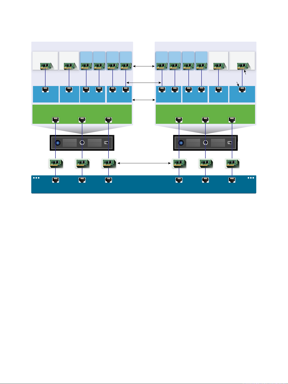
Figure 2‑1. vSphere Standard Switch architecture
A vSphere Standard Switch is very similar to a physical Ethernet switch. Virtual machine network
adapters and physical NICs on the host use the logical ports on the switch as each adapter uses one
port. Each logical port on the standard switch is a member of a single port group. For information about
maximum allowed ports and port groups, see the Configuration Maximums documentation.
Standard Port Groups
Each port group on a standard switch is identified by a network label, which must be unique to the current
host. You can use network labels to make the networking configuration of virtual machines portable
across hosts. You should give the same label to the port groups in a data center that use physical NICs
connected to one broadcast domain on the physical network. Conversely, if two port groups are
connected to physical NICs on different broadcast domains, the port groups should have distinct labels.
For example, you can create Production and Test environment port groups as virtual machine networks
on the hosts that share the same broadcast domain on the physical network.
A VLAN ID, which restricts port group traffic to a logical Ethernet segment within the physical network, is
optional. For port groups to receive the traffic that the same host sees, but from more than one VLAN, the
VLAN ID must be set to VGT (VLAN 4095).
VMware, Inc. 17

vSphere Networking
Number of Standard Ports
To ensure efficient use of host resources on ESXi hosts, the number of ports of standard switches are
dynamically scaled up and down. A standard switch on such a host can expand up to the maximum
number of ports supported on the host.
Create a vSphere Standard Switch
Create a vSphere Standard Switch to provide network connectivity for hosts, virtual machines, and to
handle VMkernel traffic. Depending on the connection type that you want to create, you can create a new
vSphere Standard Switch with a VMkernel adapter, only connect physical network adapters to the new
switch, or create the switch with a virtual machine port group.
Procedure
1 In the vSphere Web Client, navigate to the host.
2 On the Configure tab, expand Networking and select Virtual switches.
3 Click Add host networking.
4 Select a connection type for which you want to use the new standard switch and click Next.
Option Description
VMkernel Network Adapter Create a new VMkernel adapter to handle host management traffic, vMotion,
network storage, fault tolerance, or vSAN traffic.
Physical Network Adapter Add physical network adapters to an existing or a new standard switch.
Virtual Machine Port Group for a
Standard Switch
Create a new port group for virtual machine networking.
5 Select New standard switch and click Next.
6 Add physical network adapters to the new standard switch.
a Under Assigned adapters, click Add adapters.
b Select one or more physical network adapters from the list.
c From the Failover order group drop-down menu, select from the Active or Standby failover lists.
For higher throughput and to provide redundancy, configure at least two physical network
adapters in the Active list.
d Click OK.
VMware, Inc. 18

vSphere Networking
7 If you create the new standard switch with a VMkernel adapter or virtual machine port group, enter
connection settings for the adapter or the port group.
Option Description
VMkernel adapter a Enter a label that indicates the traffic type for the VMkernel adapter, for
example vMotion.
b Set a VLAN ID to identify the VLAN that the network traffic of the VMkernel
adapter will use.
c Select IPv4, Ipv6 or both.
d Select a TCP/IP stack. After you set a TCP/IP stack for the VMkernel adapter,
you cannot change it later. If you select the vMotion or the Provisioning
TCP/IP stack, you will be able to use only this stack to handle vMotion or
Provisioning traffic on the host.
e If you use the default TCP/IP stack, select from the available services.
f Configure IPv4 and IPv6 settings.
Virtual machine port group a Enter a network Label or the port group, or accept the generated label.
b Set the VLAN ID to configure VLAN handling in the port group.
8 On the Ready to Complete page, click OK.
What to do next
n
You might need to change the teaming and failover policy of the new standard switch. For example, if
the host is connected to an Etherchannel on the physical switch, you must configure the vSphere
Standard Switch with Rout based on IP hash as a load balancing algorithm. See Teaming and
Failover Policy for more information.
n
If you create the new standard switch with a port group for virtual machine networking, connect virtual
machines to the port group.
Port Group Configuration for Virtual Machines
You can add or modify a virtual machine port group to set up traffic management on a set of virtual
machines.
The Add Networking wizard in the vSphere Web Client guides you through the process to create a
virtual network to which virtual machines can connect, including creating a vSphere Standard Switch and
configuring settings for a network label.
When you set up virtual machine networks, consider whether you want to migrate the virtual machines in
the network between hosts. If so, be sure that both hosts are in the same broadcast domain—that is, the
same Layer 2 subnet.
ESXi does not support virtual machine migration between hosts in different broadcast domains because
the migrated virtual machine might require systems and resources that it would no longer have access to
in the new network. Even if your network configuration is set up as a high-availability environment or
includes intelligent switches that can resolve the virtual machine’s needs across different networks, you
might experience lag times as the Address Resolution Protocol (ARP) table updates and resumes
network traffic for the virtual machines.
VMware, Inc. 19

vSphere Networking
Virtual machines reach physical networks through uplink adapters. A vSphere Standard Switch can
transfer data to external networks only when one or more network adapters are attached to it. When two
or more adapters are attached to a single standard switch, they are transparently teamed.
Add a Virtual Machine Port Group
Create port groups on a vSphere Standard Switch to provide connectivity and common network
configuration for virtual machines.
Procedure
1 In the vSphere Web Client, navigate to the host.
2 Right-click the host and select Add Networking.
3 In Select connection type, select Virtual Machine Port Group for a Standard Switch and click
Next.
4 In Select target device, select an existing standard switch or create a new standard switch.
5 If the new port group is for an existing standard switch, navigate to the switch.
a Click Browse.
b Select a standard switch from the list and click OK.
c Click Next and go to Step 7.
6 (Optional) Оn the Create a Standard Switch page, assign physical network adapters to the standard
switch.
You can create a standard switch with or without adapters.
If you create a standard switch without physical network adapters, all traffic on that switch is confined
to that switch. No other hosts on the physical network or virtual machines on other standard switches
can send or receive traffic over this standard switch. You might create a standard switch without
physical network adapters if you want a group of virtual machines to be able to communicate with
each other, but not with other hosts or with virtual machines outside the group.
a Click Add adapters.
b Select an adapter from the Network Adapters list.
c Use the Failover order group drop-down menu to assign the adapter to Active adapters,
Standby adapters, or Unused adapters, and click OK.
d (Optional) Use the up and down arrows in the Assigned adapters list to change the position of
the adapter if needed.
e Click Next.
VMware, Inc. 20

vSphere Networking
7 On the Connection settings page, identify traffic through the ports of the group.
a Type a Network label for the port group, or accept the generated label.
b Set the VLAN ID to configure VLAN handling in the port group.
The VLAN ID also reflects the VLAN tagging mode in the port group.
VLAN Tagging Mode VLAN ID Description
External Switch Tagging (EST) 0 The virtual switch does not pass traffic associated with a VLAN.
Virtual Switch Tagging (VST) From 1 to 4094 The virtual switch tags traffic with the entered tag.
Virtual Guest Tagging (VGT) 4095 Virtual machines handle VLANs. The virtual switch passes traffic from
any VLAN.
c Click Next.
8 Review the port group settings in the Ready to complete page, and click Finish.
Click Back if you want to change any settings.
Edit a Standard Switch Port Group
By using the vSphere Web Client, you can edit the name and VLAN ID of a standard switch port group,
and override networking policies at the port group level.
Procedure
1 In the vSphere Web Client, navigate to the host.
2 On the Configure tab, expand Networking and select Virtual switches.
3 Select a standard switch from the list.
The topology diagram of the switch appears.
4 In the topology diagram of the switch, click the name of the port group.
5 Under the topology diagram title, click the Edit settings icon .
6 On the Properties page, rename the port group in the Network label text field.
7 Configure VLAN tagging in the VLAN ID drop-down menu.
VLAN Tagging Mode VLAN ID Description
External Switch Tagging (EST) 0 The virtual switch does not pass traffic associated with a VLAN.
Virtual Switch Tagging (VST) From 1 to 4094 The virtual switch tags traffic with the entered tag.
Virtual Guest Tagging (VGT) 4095 Virtual machines handle VLANs. The virtual switch passes traffic from any
VLAN.
8 On the Security page, override the switch settings for protection against MAC address impersonation
and for running virtual machines in promiscuous mode.
9 On the Traffic shaping page, override at the port group level the size of average and peak bandwidth
and of bursts.
VMware, Inc. 21

vSphere Networking
10 On the Teaming and failover page, override the teaming and failover settings inherited from the
standard switch.
You can configure traffic distribution and rerouting between the physical adapters associated with the
port group. You can also change the order in which host physical adapters are used upon failure.
11 Click OK.
Remove a Port Group from a vSphere Standard Switch
You can remove port groups from vSphere Standard Switches in case you no longer need the associated
labeled networks.
Prerequisites
Verify that there are no powered-on virtual machines connected to the port group that you want to
remove.
Procedure
1 In the vSphere Web Client, navigate to the host.
2 On the Configure tab, expand Networking and select Virtual switches.
3 Select the standard switch.
4 From the topology diagram of the switch, select the port group that you want to remove by clicking its
label.
5 From the toolbar in the switch topology, click the Remove selected port group action icon .
vSphere Standard Switch Properties
vSphere Standard Switch settings control switch-wide defaults for ports, which can be overridden by port
group settings for each standard switch. You can edit standard switch properties, such as the uplink
configuration and the number of available ports.
Number of Ports on ESXi Hosts
To ensure efficient use of host resources on ESXi hosts, the ports of virtual switches are dynamically
scaled up and down. A switch on such a host can expand up to the maximum number of ports supported
on the host. The port limit is determined based on the maximum number of virtual machines that the host
can handle.
Change the Size of the MTU on a vSphere Standard Switch
Change the size of the maximum transmission unit (MTU) on a vSphere Standard Switch to improve the
networking efficiency by increasing the amount of payload data transmitted with a single packet, that is,
enabling jumbo frames.
VMware, Inc. 22

vSphere Networking
Procedure
1 In the vSphere Web Client, navigate to the host.
2 On the Configure tab, expand Networking and select Virtual switches.
3 Select a standard switch from the table and click Edit settings.
4 Change the MTU (Bytes) value for the standard switch.
You can enable jumbo frames by setting an MTU value greater than 1500. You cannot set an MTU
size greater than 9000 bytes.
5 Click OK.
Change the Speed of a Physical Adapter
A physical adapter can become a bottleneck for network traffic if the adapter speed does not match
application requirements. You can change the connection speed and duplex of a physical adapter to
transfer data in compliance with the traffic rate.
If the physical adapter supports SR-IOV, you can enable it and configure the number of virtual functions to
use for virtual machine networking.
Procedure
1 In the vSphere Web Client, navigate to a host.
2 On the Configure tab, expand Networking and select Physical adapters.
The physical network adapters of the host appear in a table that contains details for each physical
network adapter.
3 Select the physical network adapter from the list and click the Edit adapter settings icon.
4 Select speed and duplex mode of the physical network adapter from the drop-down menu.
5 Click OK.
Add and Team Physical Adapters in a vSphere Standard Switch
Assign a physical adapter to a standard switch to provide connectivity to virtual machines and VMkernel
adapters on the host. You can form a team of NICs to distribute traffic load and to configure failover.
NIC teaming combines multiple network connections to increase throughput and provide redundancy
should a link fail. To create a team, you associate multiple physical adapters to a single vSphere Standard
Switch.
Procedure
1 In the vSphere Web Client, navigate to the host.
2 On the Configure tab, expand Networking and select Virtual switches.
3 Select the standard switch you want to add a physical adapter to.
VMware, Inc. 23

vSphere Networking
4 Click the Manage the physical network adapters connected to the selected switch icon.
5 Add one or more available physical network adapters to the switch.
a Click Add adapters.
b Select the failover order group to assign the adapters to.
The failover group determines the role of the adapter for exchanging data with the external
network, that is, active, standby or unused. By default, the adapters are added as active to the
standard switch.
c Click OK
The selected adapters appear in the selected failover group list under the Assigned Adapters list.
6 (Optional) Use the up and down arrows to change the position of an adapter in the failover groups.
7 Click OK to apply the physical adapter configuration.
View the Topology Diagram of a vSphere Standard Switch
You can examine the structure and components of a vSphere Standard Switch by using its topology
diagram.
The topology diagram of a standard switch provides a visual representation of the adapters and port
groups connected to the switch.
From the diagram you can edit the settings of a selected port group and of a selected adapter.
Procedure
1 In the vSphere Web Client, navigate to the host.
2 On the Configure tab, expand Networking and select Virtual switches.
3 Select the standard switch from the list.
The diagram appears under the list of virtual switches on the host.
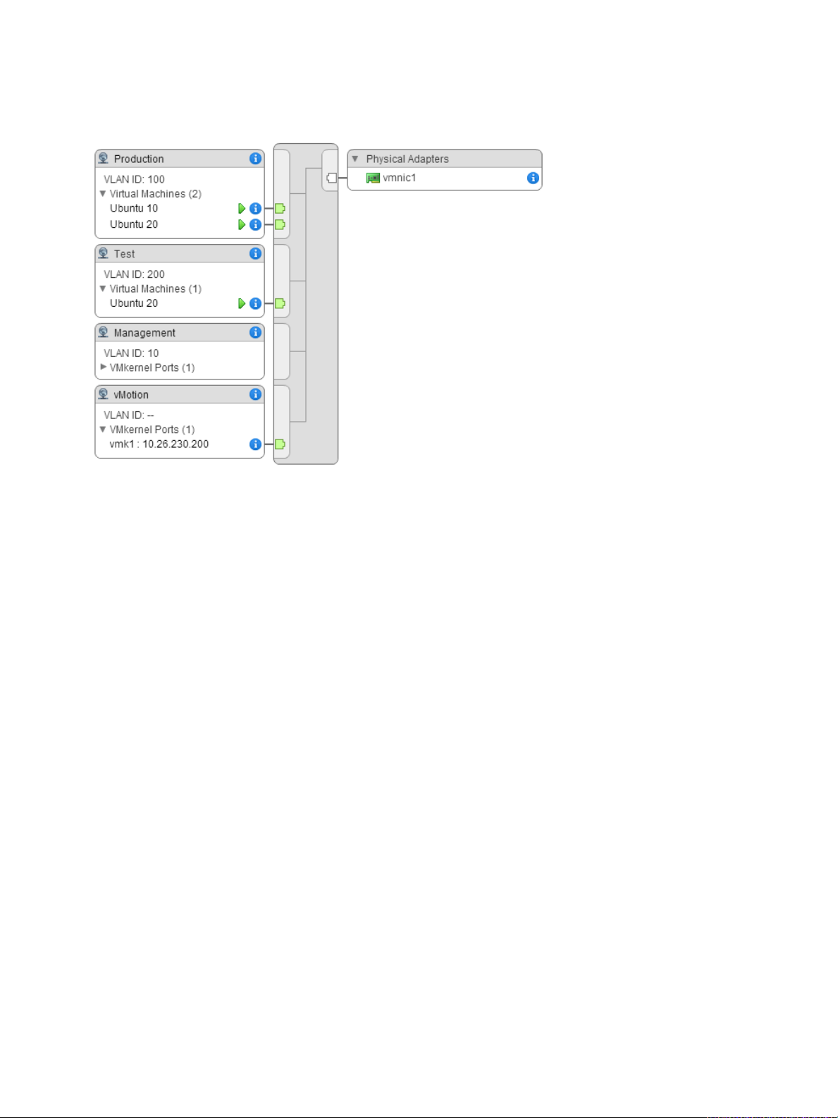
Example: Diagram of a Standard Switch That Connects the VMkernel and
Virtual Machines to the Network
In your virtual environment, a vSphere Standard Switch handles VMkernel adapters for vSphere vMotion
and for the management network, and virtual machines grouped. You can use the central topology
diagram to examine whether a virtual machine or VMkernel adapter is connected to the external network
and to identify the physical adapter that carries the data.
VMware, Inc. 24
vSphere Networking
Figure 2‑2. Topology Diagram of a Standard Switch That Connects the VMkernel and Virtual
Machines to the Network
VMware, Inc. 25

Setting Up Networking with
vSphere Distributed Switches 3
With vSphere distributed switches you can set up and configure networking in a vSphere environment.
This chapter includes the following topics:
n
vSphere Distributed Switch Architecture
n
Create a vSphere Distributed Switch
n
Upgrade a vSphere Distributed Switch to a Later Version
n
Edit General and Advanced vSphere Distributed Switch Settings
n
Managing Networking on Multiple Hosts on a vSphere Distributed Switch
n
Managing Networking on Host Proxy Switches
n
Distributed Port Groups
n
Working with Distributed Ports
n
Configuring Virtual Machine Networking on a vSphere Distributed Switch
n
Topology Diagrams of a vSphere Distributed Switch in the vSphere Web Client
vSphere Distributed Switch Architecture
A vSphere Distributed Switch provides centralized management and monitoring of the networking
configuration of all hosts that are associated with the switch. You set up a distributed switch on a
vCenter Server system, and its settings are propagated to all hosts that are associated with the switch.
VMware, Inc.
26
Uplink port group Uplink port group
Uplink2 Uplink3Uplink1
Host 1
Host 2
Uplink port group
vSphere Distributed Switch
vCenter Server
Distributed
port groups
Production network
VMkernel network
vmnic0 vmnic1 vmnic2 vmnic0 vmnic1 vmnic2
Host Proxy Switch
Production
network
VMkernel
network
Production
network
VMkernel
network
Management plane
Data plane
Virtual network
Physical network
Physical NICs
Host Proxy Switch
Physical Switch
vSphere Networking
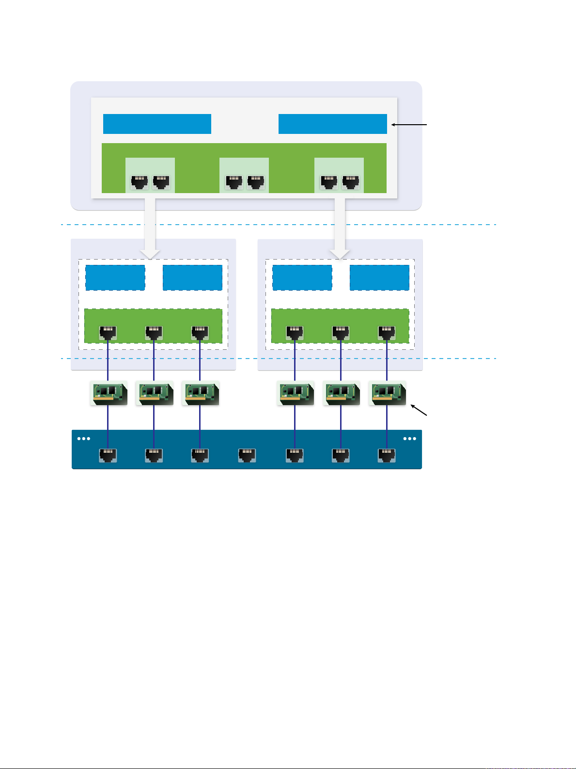
Figure 3‑1. vSphere Distributed Switch Architecture
A network switch in vSphere consists of two logical sections that are the data plane and the management
plane. The data plane implements the package switching, filtering, tagging, and so on. The management
plane is the control structure that you use to configure the data plane functionality. A vSphere Standard
Switch contains both data and management planes, and you configure and maintain each standard
switch individually.
A vSphere Distributed Switch separates the data plane and the management plane. The management
functionality of the distributed switch resides on the vCenter Server system that lets you administer the
networking configuration of your environment on a data center level. The data plane remains locally on
every host that is associated with the distributed switch. The data plane section of the distributed switch is
called a host proxy switch. The networking configuration that you create on vCenter Server (the
management plane) is automatically pushed down to all host proxy switches (the data plane).
VMware, Inc. 27

vSphere Networking
The vSphere Distributed Switch introduces two abstractions that you use to create consistent networking
configuration for physical NICs, virtual machines, and VMkernel services.
Uplink port group An uplink port group or dvuplink port group is defined during the creation of
the distributed switch and can have one or more uplinks. An uplink is a
template that you use to configure physical connections of hosts as well as
failover and load balancing policies. You map physical NICs of hosts to
uplinks on the distributed switch. At the host level, each physical NIC is
connected to an uplink port with a particular ID. You set failover and load
balancing policies over uplinks and the policies are automatically
propagated to the host proxy switches, or the data plane. In this way you
can apply consistent failover and load balancing configuration for the
physical NICs of all hosts that are associated with the distributed switch.
Distributed port group Distributed port groups provide network connectivity to virtual machines
and accommodate VMkernel traffic. You identify each distributed port group
by using a network label, which must be unique to the current data center.
You configure NIC teaming, failover, load balancing, VLAN, security, traffic
shaping , and other policies on distributed port groups. The virtual ports that
are connected to a distributed port group share the same properties that
are configured to the distributed port group. As with uplink port groups, the
configuration that you set on distributed port groups on vCenter Server (the
management plane) is automatically propagated to all hosts on the
distributed switch through their host proxy switches (the data plane). In this
way you can configure a group of virtual machines to share the same
networking configuration by associating the virtual machines to the same
distributed port group.
For example, suppose that you create a vSphere Distributed Switch on your data center and associate
two hosts with it. You configure three uplinks to the uplink port group and connect a physical NIC from
each host to an uplink. In this way, each uplink has two physical NICs from each host mapped to it, for
example Uplink 1 is configured with vmnic0 from Host 1 and Host 2. Next you create the Production and
the VMkernel network distributed port groups for virtual machine networking and VMkernel services.
Respectively, a representation of the Production and the VMkernel network port groups is also created on
Host 1 and Host 2. All policies that you set to the Production and the VMkernel network port groups are
propagated to their representations on Host 1 and Host 2.
To ensure efficient use of host resources, the number of distributed ports of proxy switches is dynamically
scaled up and down. A proxy switch on such a host can expand up to the maximum number of ports
supported on the host. The port limit is determined based on the maximum number of virtual machines
that the host can handle.
VMware, Inc. 28
VMkernel network
vCenter Server
Uplink port group
vSphere Distributed Switch
Host 1
Distributed
port groups
3 4
Host 1 Host 2
vmknic2
Host 2
VM network
0 1 2
vmknic1
Uplink 2
6
vmnic1
(Host1)
9
vmnic1
(Host2)
Uplink 3
7
vmnic2
(Host1)
10
vmnic2
(Host2)
VM1 VM2 VM3
5
vmnic0
(Host1)
8
vmnic0
(Host2)
Uplink 1
vSphere Networking
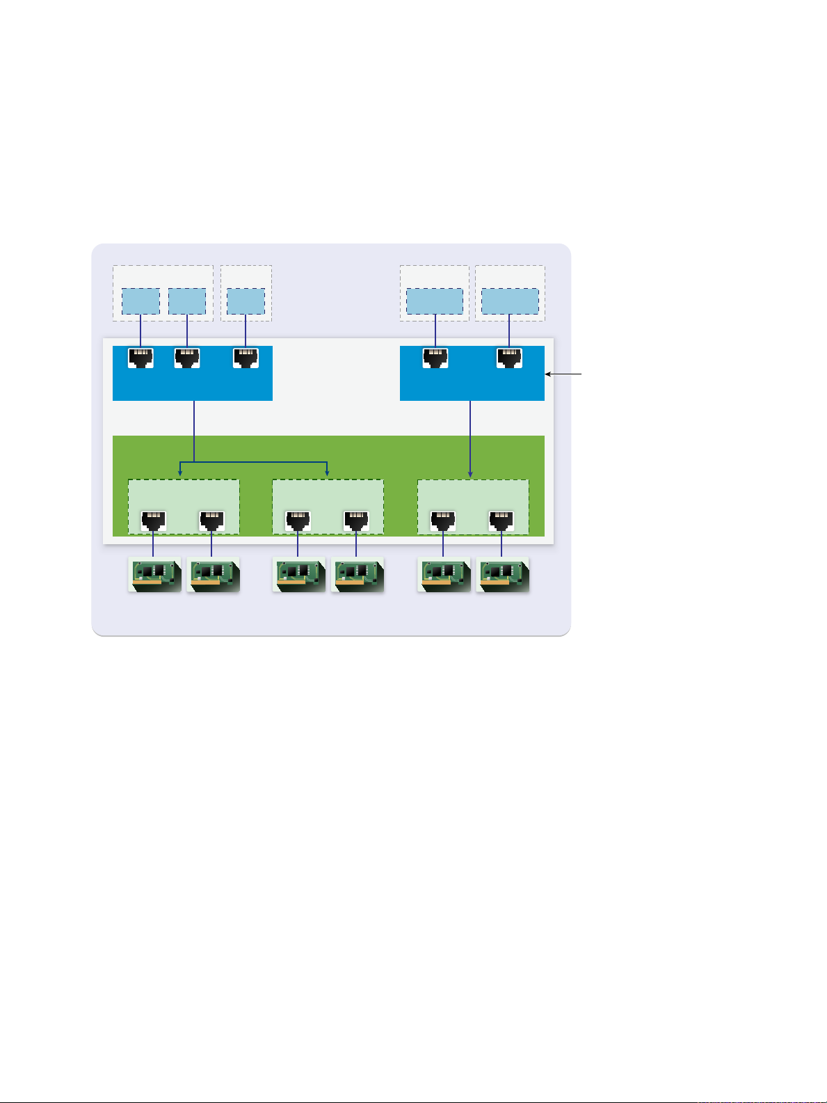
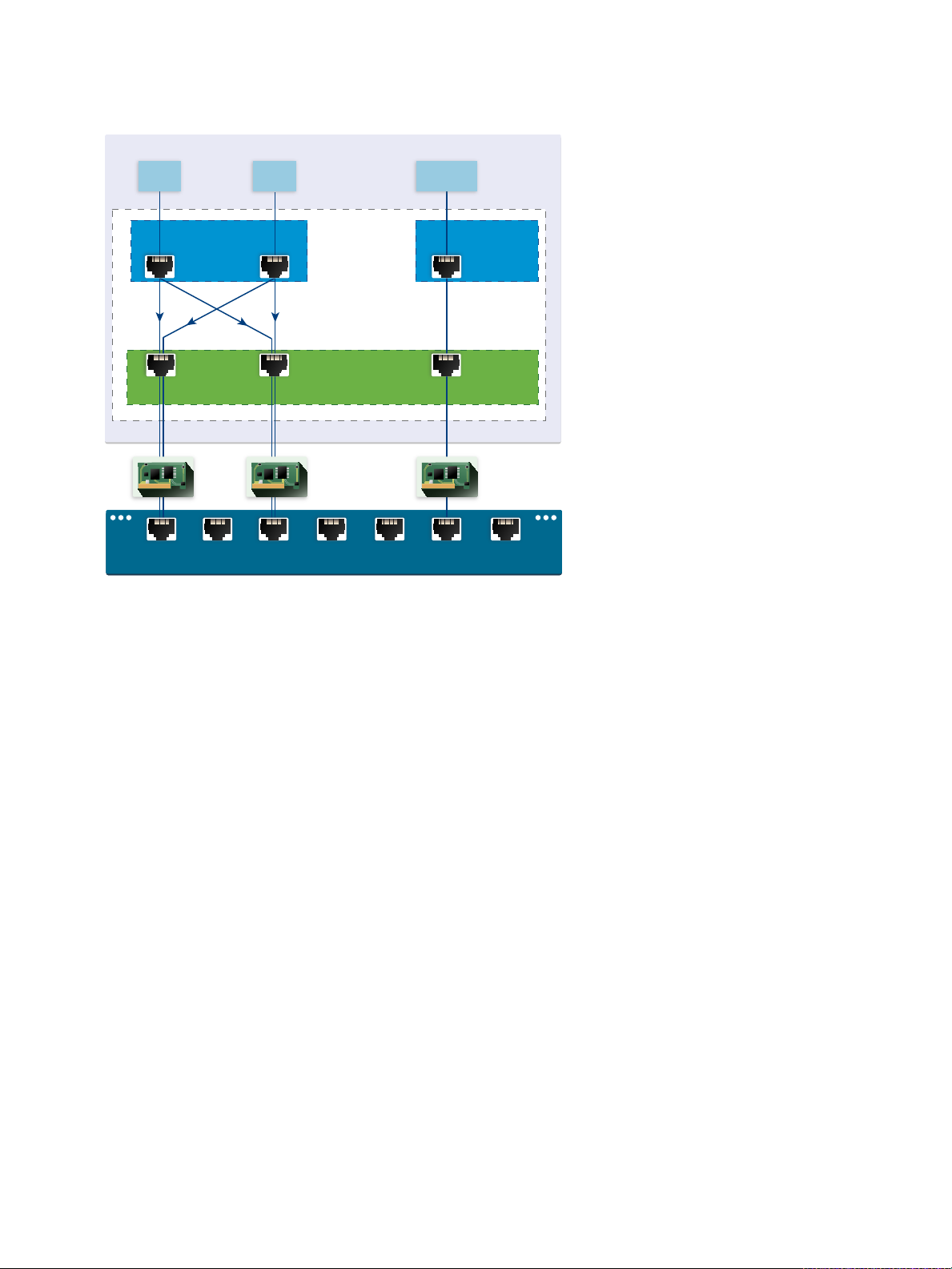
vSphere Distributed Switch Data Flow
The data flow from the virtual machines and VMkernel adapters down to the physical network depends on
the NIC teaming and load balancing policies that are set to the distributed port groups. The data flow also
depends on the port allocation on the distributed switch.
Figure 3‑2. NIC Teaming and Port Allocation on a vSphere Distributed Switch
For example, suppose that you create the VM network and the VMkernel network distributed port groups,
respectively with 3 and 2 distributed ports. The distributed switch allocates ports with IDs from 0 to 4 in
the order that you create the distributed port groups. Next, you associate Host 1 and Host 2 with the
distributed switch. The distributed switch allocates ports for every physical NIC on the hosts, as the
numbering of the ports continues from 5 in the order that you add the hosts. To provide network
connectivity on each host, you map vmnic0 to Uplink 1, vmnic1 to Uplink 2, and vmnic2 to Uplink 3.
To provide connectivity to virtual machines and to accommodate VMkernel traffic, you configure teaming
and failover to the VM network and to the VMkernel network port groups. Uplink 1 and Uplink 2 handle
the traffic for the VM network port group, and Uplink 3 handles the traffic for the VMkernel network port
group.
VMware, Inc. 29
VMkernel
network
Uplink port group
VM network
Host 1
0 1 3
vmnic0 vmnic1
5 6 7
Host Proxy
Switch
vmnic2
VM2 vmknic1VM1
Physical Switch
vSphere Networking
Figure 3‑3. Packet Flow on the Host Proxy Switch
On the host side, the packet flow from virtual machines and VMkernel services passes through particular
ports to reach the physical network. For example, a packet sent from VM1 on Host 1 first reaches port 0
on the VM network distributed port group. Because Uplink 1 and Uplink 2 handle the traffic for the VM
network port group, the packet can continue from uplink port 5 or uplink port 6 . If the packet goes through
uplink port 5, it continues to vmnic0, and if the packet goes to uplink port 6, it continues to vmnic1.
Create a vSphere Distributed Switch
Create a vSphere distributed switch on a data center to handle the networking configuration of multiple
hosts at a time from a central place.
Procedure
1 In the vSphere Web Client, navigate to a data center.
2 In the navigator, right-click the data center and select Distributed Switch > New Distributed Switch.
3 On the Name and location page, type a name for the new distributed switch, or accept the generated
name, and click Next.
VMware, Inc. 30
 Loading...