

Page 1

vSphere Resource
Management
17 APR 2018
VMware vSphere 6.7
VMware ESXi 6.7
vCenter Server 6.7
Page 2

vSphere Resource Management
You can find the most up-to-date technical documentation on the VMware website at:
https://docs.vmware.com/
If you have comments about this documentation, submit your feedback to
docfeedback@vmware.com
VMware, Inc.
3401 Hillview Ave.
Palo Alto, CA 94304
www.vmware.com
Copyright © 2006–2018 VMware, Inc. All rights reserved. Copyright and trademark information.
VMware, Inc. 2
Page 3

Contents
About vSphere Resource Management 7
Getting Started with Resource Management 9
1
Resource Types 9
Resource Providers 9
Resource Consumers 10
Goals of Resource Management 10
Configuring Resource Allocation Settings 11
2
Resource Allocation Shares 11
Resource Allocation Reservation 12
Resource Allocation Limit 13
Resource Allocation Settings Suggestions 13
Edit Settings 14
Changing Resource Allocation Settings—Example 14
Admission Control 15
CPU Virtualization Basics 17
3
Software-Based CPU Virtualization 17
Hardware-Assisted CPU Virtualization 18
Virtualization and Processor-Specific Behavior 18
Performance Implications of CPU Virtualization 18
VMware, Inc.
Administering CPU Resources 20
4
View Processor Information 20
Specifying CPU Configuration 21
Multicore Processors 21
Hyperthreading 22
Using CPU Affinity 23
Host Power Management Policies 25
Memory Virtualization Basics 28
5
Virtual Machine Memory 28
Memory Overcommitment 29
Memory Sharing 30
Memory Virtualization 30
Support for Large Page Sizes 32
3
Page 4

vSphere Resource Management
Administering Memory Resources 33
6
Understanding Memory Overhead 33
How ESXi Hosts Allocate Memory 35
Memory Reclamation 36
Using Swap Files 37
Sharing Memory Across Virtual Machines 42
Memory Compression 42
Measuring and Differentiating Types of Memory Usage 43
Memory Reliability 45
About System Swap 45
Persistent Memory 47
7
Configuring Virtual Graphics 49
8
View GPU Statistics 49
Add an NVIDIA GRID vGPU to a Virtual Machine 50
Configuring Host Graphics 50
Configuring Graphics Devices 51
Managing Storage I/O Resources 52
9
About Virtual Machine Storage Policies 53
About I/O Filters 53
Storage I/O Control Requirements 54
Storage I/O Control Resource Shares and Limits 54
Set Storage I/O Control Resource Shares and Limits 55
Enable Storage I/O Control 56
Set Storage I/O Control Threshold Value 56
Storage DRS Integration with Storage Profiles 58
Managing Resource Pools 59
10
Why Use Resource Pools? 60
Create a Resource Pool 63
Edit a Resource Pool 64
Add a Virtual Machine to a Resource Pool 64
Remove a Virtual Machine from a Resource Pool 65
Remove a Resource Pool 66
Resource Pool Admission Control 66
Creating a DRS Cluster 69
11
Admission Control and Initial Placement 69
Virtual Machine Migration 71
DRS Cluster Requirements 73
VMware, Inc. 4
Page 5

vSphere Resource Management
Configuring DRS with Virtual Flash 75
Create a Cluster 76
Edit Cluster Settings 76
Set a Custom Automation Level for a Virtual Machine 78
Disable DRS 79
Restore a Resource Pool Tree 79
Using DRS Clusters to Manage Resources 81
12
Adding Hosts to a Cluster 81
Adding Virtual Machines to a Cluster 83
Removing Virtual Machines from a Cluster 83
Removing a Host from a Cluster 84
DRS Cluster Validity 86
Managing Power Resources 91
Using DRS Affinity Rules 96
Creating a Datastore Cluster 102
13
Initial Placement and Ongoing Balancing 103
Storage Migration Recommendations 103
Create a Datastore Cluster 104
Enable and Disable Storage DRS 104
Set the Automation Level for Datastore Clusters 105
Setting the Aggressiveness Level for Storage DRS 105
Datastore Cluster Requirements 107
Adding and Removing Datastores from a Datastore Cluster 107
Using Datastore Clusters to Manage Storage Resources 109
14
Using Storage DRS Maintenance Mode 109
Applying Storage DRS Recommendations 111
Change Storage DRS Automation Level for a Virtual Machine 112
Set Up Off-Hours Scheduling for Storage DRS 112
Storage DRS Anti-Affinity Rules 113
Clear Storage DRS Statistics 117
Storage vMotion Compatibility with Datastore Clusters 117
Using NUMA Systems with ESXi 119
15
What is NUMA? 119
How ESXi NUMA Scheduling Works 120
VMware NUMA Optimization Algorithms and Settings 121
Resource Management in NUMA Architectures 123
Using Virtual NUMA 123
Specifying NUMA Controls 124
VMware, Inc. 5
Page 6

vSphere Resource Management
Advanced Attributes 128
16
Set Advanced Host Attributes 128
Set Advanced Virtual Machine Attributes 131
Latency Sensitivity 133
About Reliable Memory 134
Backing Guest vRAM with 1GB Pages 134
Fault Definitions 136
17
Virtual Machine is Pinned 137
Virtual Machine not Compatible with any Host 137
VM/VM DRS Rule Violated when Moving to another Host 137
Host Incompatible with Virtual Machine 137
Host Has Virtual Machine That Violates VM/VM DRS Rules 137
Host has Insufficient Capacity for Virtual Machine 138
Host in Incorrect State 138
Host Has Insufficient Number of Physical CPUs for Virtual Machine 138
Host has Insufficient Capacity for Each Virtual Machine CPU 138
The Virtual Machine Is in vMotion 138
No Active Host in Cluster 138
Insufficient Resources 138
Insufficient Resources to Satisfy Configured Failover Level for HA 139
No Compatible Hard Affinity Host 139
No Compatible Soft Affinity Host 139
Soft Rule Violation Correction Disallowed 139
Soft Rule Violation Correction Impact 139
DRS Troubleshooting Information 140
18
Cluster Problems 140
Host Problems 144
Virtual Machine Problems 147
VMware, Inc. 6
Page 7

About vSphere Resource Management
vSphere Resource Management describes resource management for VMware® ESXi and vCenter
®
Server environments.
This documentation focuses on the following topics.
n
Resource allocation and resource management concepts
n
Virtual machine attributes and admission control
n
Resource pools and how to manage them
n
Clusters, vSphere® Distributed Resource Scheduler (DRS), vSphere Distributed Power Management
(DPM), and how to work with them
n
Datastore clusters, Storage DRS, Storage I/O Control, and how to work with them
n
Advanced resource management options
n
Performance considerations
Intended Audience
This information is for system administrators who want to understand how the system manages resources
and how they can customize the default behavior. It’s also essential for anyone who wants to understand
and use resource pools, clusters, DRS, datastore clusters, Storage DRS, Storage I/O Control, or vSphere
DPM.
This documentation assumes you have a working knowledge of VMware ESXi and of vCenter Server.
Note In this document, "Memory" can refer to physical RAM or Persistent Memory.
vSphere Client and vSphere Web Client
The instructions in this guide are specific primarily to the vSphere Client (an HTML5-based GUI). Most
instructions also apply to the vSphere Web Client (a Flex-based GUI).
VMware, Inc.
7
Page 8

vSphere Resource Management
For the workflows that significantly differ between the two clients, there are duplicate procedures. The
procedures indicate when they are intended exclusively for the vSphere Client or the vSphere Web Client.
Note In vSphere 6.7, most of the vSphere Web Client functionality is implemented in the vSphere Client.
For an up-to-date list of the unsupported functionality, see Functionality Updates for the vSphere Client.
VMware, Inc. 8
Page 9

Getting Started with Resource
Management 1
To understand resource management, you must be aware of its components, its goals, and how best to
implement it in a cluster setting.
Resource allocation settings for a virtual machine (shares, reservation, and limit) are discussed, including
how to set them and how to view them. Also, admission control, the process whereby resource allocation
settings are validated against existing resources is explained.
Resource management is the allocation of resources from resource providers to resource consumers.
The need for resource management arises from the overcommitment of resources—that is, more demand
than capacity and from the fact that demand and capacity vary over time. Resource management allows
you to dynamically reallocate resources, so that you can more efficiently use available capacity.
Note In this chapter, "Memory" refers to physical RAM.
This chapter includes the following topics:
n
Resource Types
n
Resource Providers
n
Resource Consumers
n
Goals of Resource Management
Resource Types
Resources include CPU, memory, power, storage, and network resources.
Note ESXi manages network bandwidth and disk resources on a per-host basis, using network traffic
shaping and a proportional share mechanism, respectively.
Resource Providers
Hosts and clusters, including datastore clusters, are providers of physical resources.
For hosts, available resources are the host’s hardware specification, minus the resources used by the
virtualization software.
VMware, Inc.
9
Page 10

vSphere Resource Management
A cluster is a group of hosts. You can create a cluster using vSphere Client, and add multiple hosts to the
cluster. vCenter Server manages these hosts’ resources jointly: the cluster owns all of the CPU and
memory of all hosts. You can enable the cluster for joint load balancing or failover. See Chapter 11
Creating a DRS Cluster for more information.
A datastore cluster is a group of datastores. Like DRS clusters, you can create a datastore cluster using
the vSphere Client, and add multiple datstores to the cluster. vCenter Server manages the datastore
resources jointly. You can enable Storage DRS to balance I/O load and space utilization. See Chapter 13
Creating a Datastore Cluster.
Resource Consumers
Virtual machines are resource consumers.
The default resource settings assigned during creation work well for most machines. You can later edit
the virtual machine settings to allocate a share-based percentage of the total CPU, memory, and storage
I/O of the resource provider or a guaranteed reservation of CPU and memory. When you power on that
virtual machine, the server checks whether enough unreserved resources are available and allows power
on only if there are enough resources. This process is called admission control.
A resource pool is a logical abstraction for flexible management of resources. Resource pools can be
grouped into hierarchies and used to hierarchically partition available CPU and memory resources.
Accordingly, resource pools can be considered both resource providers and consumers. They provide
resources to child resource pools and virtual machines, but are also resource consumers because they
consume their parents’ resources. See Chapter 10 Managing Resource Pools.
ESXi hosts allocate each virtual machine a portion of the underlying hardware resources based on a
number of factors:
n
Resource limits defined by the user.
n
Total available resources for the ESXi host (or the cluster).
n
Number of virtual machines powered on and resource usage by those virtual machines.
n
Overhead required to manage the virtualization.
Goals of Resource Management
When managing your resources, you must be aware of what your goals are.
In addition to resolving resource overcommitment, resource management can help you accomplish the
following:
n
Performance Isolation: Prevent virtual machines from monopolizing resources and guarantee
predictable service rates.
n
Efficient Usage: Exploit undercommitted resources and overcommit with graceful degradation.
n
Easy Administration: Control the relative importance of virtual machines, provide flexible dynamic
partitioning, and meet absolute service-level agreements.
VMware, Inc. 10
Page 11

Configuring Resource Allocation
Settings 2
When available resource capacity does not meet the demands of the resource consumers (and
virtualization overhead), administrators might need to customize the amount of resources that are
allocated to virtual machines or to the resource pools in which they reside.
Use the resource allocation settings (shares, reservation, and limit) to determine the amount of CPU,
memory, and storage resources provided for a virtual machine. In particular, administrators have several
options for allocating resources.
n
Reserve the physical resources of the host or cluster.
n
Set an upper bound on the resources that can be allocated to a virtual machine.
n
Guarantee that a particular virtual machine is always allocated a higher percentage of the physical
resources than other virtual machines.
Note In this chapter, "Memory" refers to physical RAM.
This chapter includes the following topics:
n
Resource Allocation Shares
n
Resource Allocation Reservation
n
Resource Allocation Limit
n
Resource Allocation Settings Suggestions
n
Edit Settings
n
Changing Resource Allocation Settings—Example
n
Admission Control
Resource Allocation Shares
Shares specify the relative importance of a virtual machine (or resource pool). If a virtual machine has
twice as many shares of a resource as another virtual machine, it is entitled to consume twice as much of
that resource when these two virtual machines are competing for resources.
Shares are typically specified as High, Normal, or Low and these values specify share values with a
4:2:1 ratio, respectively. You can also select Custom to assign a specific number of shares (which
expresses a proportional weight) to each virtual machine.
VMware, Inc.
11
Page 12

vSphere Resource Management
Specifying shares makes sense only with regard to sibling virtual machines or resource pools, that is,
virtual machines or resource pools with the same parent in the resource pool hierarchy. Siblings share
resources according to their relative share values, bounded by the reservation and limit. When you assign
shares to a virtual machine, you always specify the priority for that virtual machine relative to other
powered-on virtual machines.
The following table shows the default CPU and memory share values for a virtual machine. For resource
pools, the default CPU and memory share values are the same, but must be multiplied as if the resource
pool were a virtual machine with four virtual CPUs and 16 GB of memory.
Table 2‑1. Share Values
Setting CPU share values Memory share values
High 2000 shares per virtual CPU 20 shares per megabyte of configured virtual machine
memory.
Normal 1000 shares per virtual CPU 10 shares per megabyte of configured virtual machine
memory.
Low 500 shares per virtual CPU 5 shares per megabyte of configured virtual machine
memory.
For example, an SMP virtual machine with two virtual CPUs and 1GB RAM with CPU and memory shares
set to Normal has 2x1000=2000 shares of CPU and 10x1024=10240 shares of memory.
Note Virtual machines with more than one virtual CPU are called SMP (symmetric multiprocessing)
virtual machines. ESXi supports up to 128 virtual CPUs per virtual machine.
The relative priority represented by each share changes when a new virtual machine is powered on. This
affects all virtual machines in the same resource pool. All of the virtual machines have the same number
of virtual CPUs. Consider the following examples.
n
Two CPU-bound virtual machines run on a host with 8GHz of aggregate CPU capacity. Their CPU
shares are set to Normal and get 4GHz each.
n
A third CPU-bound virtual machine is powered on. Its CPU shares value is set to High, which means
it should have twice as many shares as the machines set to Normal. The new virtual machine
receives 4GHz and the two other machines get only 2GHz each. The same result occurs if the user
specifies a custom share value of 2000 for the third virtual machine.
Resource Allocation Reservation
A reservation specifies the guaranteed minimum allocation for a virtual machine.
vCenter Server or ESXi allows you to power on a virtual machine only if there are enough unreserved
resources to satisfy the reservation of the virtual machine. The server guarantees that amount even when
the physical server is heavily loaded. The reservation is expressed in concrete units (megahertz or
megabytes).
VMware, Inc. 12
Page 13

vSphere Resource Management
For example, assume you have 2GHz available and specify a reservation of 1GHz for VM1 and 1GHz for
VM2. Now each virtual machine is guaranteed to get 1GHz if it needs it. However, if VM1 is using only
500MHz, VM2 can use 1.5GHz.
Reservation defaults to 0. You can specify a reservation if you need to guarantee that the minimum
required amounts of CPU or memory are always available for the virtual machine.
Resource Allocation Limit
Limit specifies an upper bound for CPU, memory, or storage I/O resources that can be allocated to a
virtual machine.
A server can allocate more than the reservation to a virtual machine, but never allocates more than the
limit, even if there are unused resources on the system. The limit is expressed in concrete units
(megahertz, megabytes, or I/O operations per second).
CPU, memory, and storage I/O resource limits default to unlimited. When the memory limit is unlimited,
the amount of memory configured for the virtual machine when it was created becomes its effective limit.
In most cases, it is not necessary to specify a limit. There are benefits and drawbacks:
n
Benefits — Assigning a limit is useful if you start with a small number of virtual machines and want to
manage user expectations. Performance deteriorates as you add more virtual machines. You can
simulate having fewer resources available by specifying a limit.
n
Drawbacks — You might waste idle resources if you specify a limit. The system does not allow virtual
machines to use more resources than the limit, even when the system is underutilized and idle
resources are available. Specify the limit only if you have good reasons for doing so.
Resource Allocation Settings Suggestions
Select resource allocation settings (reservation, limit and shares) that are appropriate for your ESXi
environment.
The following guidelines can help you achieve better performance for your virtual machines.
n
Use Reservation to specify the minimum acceptable amount of CPU or memory, not the amount you
want to have available. The amount of concrete resources represented by a reservation does not
change when you change the environment, such as by adding or removing virtual machines. The host
assigns additional resources as available based on the limit for your virtual machine, the number of
shares and estimated demand.
n
When specifying the reservations for virtual machines, do not commit all resources (plan to leave at
least 10% unreserved). As you move closer to fully reserving all capacity in the system, it becomes
increasingly difficult to make changes to reservations and to the resource pool hierarchy without
violating admission control. In a DRS-enabled cluster, reservations that fully commit the capacity of
the cluster or of individual hosts in the cluster can prevent DRS from migrating virtual machines
between hosts.
VMware, Inc. 13
Page 14

vSphere Resource Management
n
If you expect frequent changes to the total available resources, use Shares to allocate resources
fairly across virtual machines. If you use Shares, and you upgrade the host, for example, each virtual
machine stays at the same priority (keeps the same number of shares) even though each share
represents a larger amount of memory, CPU, or storage I/O resources.
Edit Settings
Use the Edit Settings dialog box to change allocations for memory and CPU resources.
Procedure
1 Browse to the virtual machine in the vSphere Client.
2 Right-click and select Edit Settings.
3 Edit the CPU Resources.
Option Description
Shares CPU shares for this resource pool with respect to the parent’s total. Sibling
resource pools share resources according to their relative share values bounded
by the reservation and limit. Select Low, Normal, or High, which specify share
values respectively in a 1:2:4 ratio. Select Custom to give each virtual machine a
specific number of shares, which expresses a proportional weight.
Reservation Guaranteed CPU allocation for this resource pool.
Limit Upper limit for this resource pool’s CPU allocation. Select Unlimited to specify no
upper limit.
4 Edit the Memory Resources.
Option Description
Shares Memory shares for this resource pool with respect to the parent’s total. Sibling
resource pools share resources according to their relative share values bounded
by the reservation and limit. Select Low, Normal, or High, which specify share
values respectively in a 1:2:4 ratio. Select Custom to give each virtual machine a
specific number of shares, which expresses a proportional weight.
Reservation Guaranteed memory allocation for this resource pool.
Limit Upper limit for this resource pool’s memory allocation. Select Unlimited to specify
no upper limit.
5 Click OK.
Changing Resource Allocation Settings—Example
The following example illustrates how you can change resource allocation settings to improve virtual
machine performance.
Assume that on an ESXi host, you have created two new virtual machines—one each for your QA (VM-
QA) and Marketing (VM-Marketing) departments.
VMware, Inc. 14
Page 15

VM-QA
host
VM-Marketing
vSphere Resource Management
Figure 2‑1. Single Host with Two Virtual Machines
In the following example, assume that VM-QA is memory intensive and accordingly you want to change
the resource allocation settings for the two virtual machines to:
n
Specify that, when system memory is overcommitted, VM-QA can use twice as much CPU and
memory resources as the Marketing virtual machine. Set the CPU shares and memory shares for
VM-QA to High and for VM-Marketing set them to Normal.
n
Ensure that the Marketing virtual machine has a certain amount of guaranteed CPU resources. You
can do so using a reservation setting.
Procedure
1 Browse to the virtual machines in the vSphere Client.
2 Right-click VM-QA, the virtual machine for which you want to change shares, and select Edit
Settings.
3 Under Virtual Hardware, expand CPU and select High from the Shares drop-down menu.
4 Under Virtual Hardware, expand Memory and select High from the Shares drop-down menu.
5 Click OK.
6 Right-click the marketing virtual machine (VM-Marketing) and select Edit Settings.
7 Under Virtual Hardware, expand CPU and change the Reservation value to the desired number.
8 Click OK.
Admission Control
When you power on a virtual machine, the system checks the amount of CPU and memory resources that
have not yet been reserved. Based on the available unreserved resources, the system determines
whether it can guarantee the reservation for which the virtual machine is configured (if any). This process
is called admission control.
If enough unreserved CPU and memory are available, or if there is no reservation, the virtual machine is
powered on. Otherwise, an Insufficient Resources warning appears.
Note In addition to the user-specified memory reservation, for each virtual machine there is also an
amount of overhead memory. This extra memory commitment is included in the admission control
calculation.
VMware, Inc. 15
Page 16

vSphere Resource Management
When the vSphere DPM feature is enabled, hosts might be placed in standby mode (that is, powered off)
to reduce power consumption. The unreserved resources provided by these hosts are considered
available for admission control. If a virtual machine cannot be powered on without these resources, a
recommendation to power on sufficient standby hosts is made.
VMware, Inc. 16
Page 17

CPU Virtualization Basics 3
CPU virtualization emphasizes performance and runs directly on the processor whenever possible. The
underlying physical resources are used whenever possible and the virtualization layer runs instructions
only as needed to make virtual machines operate as if they were running directly on a physical machine.
CPU virtualization is not the same thing as emulation. ESXi does not use emulation to run virtual CPUs.
With emulation, all operations are run in software by an emulator. A software emulator allows programs to
run on a computer system other than the one for which they were originally written. The emulator does
this by emulating, or reproducing, the original computer’s behavior by accepting the same data or inputs
and achieving the same results. Emulation provides portability and runs software designed for one
platform across several platforms.
When CPU resources are overcommitted, the ESXi host time-slices the physical processors across all
virtual machines so each virtual machine runs as if it has its specified number of virtual processors. When
an ESXi host runs multiple virtual machines, it allocates to each virtual machine a share of the physical
resources. With the default resource allocation settings, all virtual machines associated with the same
host receive an equal share of CPU per virtual CPU. This means that a single-processor virtual machines
is assigned only half of the resources of a dual-processor virtual machine.
This chapter includes the following topics:
n
Software-Based CPU Virtualization
n
Hardware-Assisted CPU Virtualization
n
Virtualization and Processor-Specific Behavior
n
Performance Implications of CPU Virtualization
Software-Based CPU Virtualization
With software-based CPU virtualization, the guest application code runs directly on the processor, while
the guest privileged code is translated and the translated code runs on the processor.
The translated code is slightly larger and usually runs more slowly than the native version. As a result,
guest applications, which have a small privileged code component, run with speeds very close to native.
Applications with a significant privileged code component, such as system calls, traps, or page table
updates can run slower in the virtualized environment.
VMware, Inc.
17
Page 18

vSphere Resource Management
Hardware-Assisted CPU Virtualization
Certain processors provide hardware assistance for CPU virtualization.
When using this assistance, the guest can use a separate mode of execution called guest mode. The
guest code, whether application code or privileged code, runs in the guest mode. On certain events, the
processor exits out of guest mode and enters root mode. The hypervisor executes in the root mode,
determines the reason for the exit, takes any required actions, and restarts the guest in guest mode.
When you use hardware assistance for virtualization, there is no need to translate the code. As a result,
system calls or trap-intensive workloads run very close to native speed. Some workloads, such as those
involving updates to page tables, lead to a large number of exits from guest mode to root mode.
Depending on the number of such exits and total time spent in exits, hardware-assisted CPU virtualization
can speed up execution significantly.
Virtualization and Processor-Specific Behavior
Although VMware software virtualizes the CPU, the virtual machine detects the specific model of the
processor on which it is running.
Processor models might differ in the CPU features they offer, and applications running in the virtual
machine can make use of these features. Therefore, it is not possible to use vMotion® to migrate virtual
machines between systems running on processors with different feature sets. You can avoid this
restriction, in some cases, by using Enhanced vMotion Compatibility (EVC) with processors that support
this feature. See the vCenter Server and Host Management documentation for more information.
Performance Implications of CPU Virtualization
CPU virtualization adds varying amounts of overhead depending on the workload and the type of
virtualization used.
An application is CPU-bound if it spends most of its time executing instructions rather than waiting for
external events such as user interaction, device input, or data retrieval. For such applications, the CPU
virtualization overhead includes the additional instructions that must be executed. This overhead takes
CPU processing time that the application itself can use. CPU virtualization overhead usually translates
into a reduction in overall performance.
For applications that are not CPU-bound, CPU virtualization likely translates into an increase in CPU use.
If spare CPU capacity is available to absorb the overhead, it can still deliver comparable performance in
terms of overall throughput.
VMware, Inc. 18
Page 19

vSphere Resource Management
ESXi supports up to 128 virtual processors (CPUs) for each virtual machine.
Note Deploy single-threaded applications on uniprocessor virtual machines, instead of on SMP virtual
machines that have multiple CPUs, for the best performance and resource use.
Single-threaded applications can take advantage only of a single CPU. Deploying such applications in
dual-processor virtual machines does not speed up the application. Instead, it causes the second virtual
CPU to use physical resources that other virtual machines could otherwise use.
VMware, Inc. 19
Page 20

Administering CPU Resources 4
You can configure virtual machines with one or more virtual processors, each with its own set of registers
and control structures.
When a virtual machine is scheduled, its virtual processors are scheduled to run on physical processors.
The VMkernel Resource Manager schedules the virtual CPUs on physical CPUs, thereby managing the
virtual machine’s access to physical CPU resources. ESXi supports virtual machines with up to 128 virtual
CPUs.
Note In this chapter, "Memory" can refer to physical RAM or Persistent Memory.
This chapter includes the following topics:
n
View Processor Information
n
Specifying CPU Configuration
n
Multicore Processors
n
Hyperthreading
n
Using CPU Affinity
n
Host Power Management Policies
View Processor Information
You can access information about current CPU configuration in the vSphere Client.
Procedure
1 Browse to the host in the vSphere Client.
2 Click Configure and expand Hardware.
3 Select Processors to view the information about the number and type of physical processors and the
number of logical processors.
Note In hyperthreaded systems, each hardware thread is a logical processor. For example, a dual-
core processor with hyperthreading enabled has two cores and four logical processors.
VMware, Inc.
20
Page 21

vSphere Resource Management
Specifying CPU Configuration
You can specify CPU configuration to improve resource management. However, if you do not customize
CPU configuration, the ESXi host uses defaults that work well in most situations.
You can specify CPU configuration in the following ways:
n
Use the attributes and special features available through the vSphere Client. The vSphere Client
allows you to connect to the ESXi host or a vCenter Server system.
n
Use advanced settings under certain circumstances.
n
Use the vSphere SDK for scripted CPU allocation.
n
Use hyperthreading.
Multicore Processors
Multicore processors provide many advantages for a host performing multitasking of virtual machines.
Note In this topic, "Memory" can refer to physical RAM or Persistent Memory.
Intel and AMD have developed processors which combine two or more processor cores into a single
integrated circuit (often called a package or socket). VMware uses the term socket to describe a single
package which can have one or more processor cores with one or more logical processors in each core.
A dual-core processor, for example, provides almost double the performance of a single-core processor,
by allowing two virtual CPUs to run at the same time. Cores within the same processor are typically
configured with a shared last-level cache used by all cores, potentially reducing the need to access
slower main memory. A shared memory bus that connects a physical processor to main memory can limit
performance of its logical processors when the virtual machines running on them are running memory-
intensive workloads which compete for the same memory bus resources.
Each logical processor of each processor core is used independently by the ESXi CPU scheduler to run
virtual machines, providing capabilities similar to SMP systems. For example, a two-way virtual machine
can have its virtual processors running on logical processors that belong to the same core, or on logical
processors on different physical cores.
The ESXi CPU scheduler can detect the processor topology and the relationships between processor
cores and the logical processors on them. It uses this information to schedule virtual machines and
optimize performance.
The ESXi CPU scheduler can interpret processor topology, including the relationship between sockets,
cores, and logical processors. The scheduler uses topology information to optimize the placement of
virtual CPUs onto different sockets. This optimization can maximize overall cache usage, and to improve
cache affinity by minimizing virtual CPU migrations.
VMware, Inc. 21
Page 22

vSphere Resource Management
Hyperthreading
Hyperthreading technology allows a single physical processor core to behave like two logical processors.
The processor can run two independent applications at the same time. To avoid confusion between
logical and physical processors, Intel refers to a physical processor as a socket, and the discussion in this
chapter uses that terminology as well.
Intel Corporation developed hyperthreading technology to enhance the performance of its Pentium IV and
Xeon processor lines. Hyperthreading technology allows a single processor core to execute two
independent threads simultaneously.
While hyperthreading does not double the performance of a system, it can increase performance by
better utilizing idle resources leading to greater throughput for certain important workload types. An
application running on one logical processor of a busy core can expect slightly more than half of the
throughput that it obtains while running alone on a non-hyperthreaded processor. Hyperthreading
performance improvements are highly application-dependent, and some applications might see
performance degradation with hyperthreading because many processor resources (such as the cache)
are shared between logical processors.
Note On processors with Intel Hyper-Threading technology, each core can have two logical processors
which share most of the core's resources, such as memory caches and functional units. Such logical
processors are usually called threads.
Many processors do not support hyperthreading and as a result have only one thread per core. For such
processors, the number of cores also matches the number of logical processors. The following
processors support hyperthreading and have two threads per core.
n
Processors based on the Intel Xeon 5500 processor microarchitecture.
n
Intel Pentium 4 (HT-enabled)
n
Intel Pentium EE 840 (HT-enabled)
Hyperthreading and ESXi Hosts
A host that is enabled for hyperthreading should behave similarly to a host without hyperthreading. You
might need to consider certain factors if you enable hyperthreading, however.
ESXi hosts manage processor time intelligently to guarantee that load is spread smoothly across
processor cores in the system. Logical processors on the same core have consecutive CPU numbers, so
that CPUs 0 and 1 are on the first core together, CPUs 2 and 3 are on the second core, and so on. Virtual
machines are preferentially scheduled on two different cores rather than on two logical processors on the
same core.
VMware, Inc. 22
Page 23

vSphere Resource Management
If there is no work for a logical processor, it is put into a halted state, which frees its execution resources
and allows the virtual machine running on the other logical processor on the same core to use the full
execution resources of the core. The VMware scheduler properly accounts for this halt time, and charges
a virtual machine running with the full resources of a core more than a virtual machine running on a half
core. This approach to processor management ensures that the server does not violate any of the
standard ESXi resource allocation rules.
Consider your resource management needs before you enable CPU affinity on hosts using
hyperthreading. For example, if you bind a high priority virtual machine to CPU 0 and another high priority
virtual machine to CPU 1, the two virtual machines have to share the same physical core. In this case, it
can be impossible to meet the resource demands of these virtual machines. Ensure that any custom
affinity settings make sense for a hyperthreaded system.
Enable Hyperthreading
To enable hyperthreading, you must first enable it in your system's BIOS settings and then turn it on in the
vSphere Client. Hyperthreading is enabled by default.
Consult your system documentation to determine whether your CPU supports hyperthreading.
Procedure
1 Ensure that your system supports hyperthreading technology.
2 Enable hyperthreading in the system BIOS.
Some manufacturers label this option Logical Processor, while others call it Enable
Hyperthreading.
3 Ensure that hyperthreading is enabled for the ESXi host.
a Browse to the host in the vSphere Client.
b Click Configure.
c Under System, click Advanced System Settings and select VMkernel.Boot.hyperthreading.
You must restart the host for the setting to take effect. Hyperthreading is enabled if the value is
true.
4 Under Hardware, click Processors to view the number of Logical processors.
Hyperthreading is enabled.
Using CPU Anity
By specifying a CPU affinity setting for each virtual machine, you can restrict the assignment of virtual
machines to a subset of the available processors in multiprocessor systems. By using this feature, you
can assign each virtual machine to processors in the specified affinity set.
CPU affinity specifies virtual machine-to-processor placement constraints and is different from the
relationship created by a VM-VM or VM-Host affinity rule, which specifies virtual machine-to-virtual
machine host placement constraints.
VMware, Inc. 23
Page 24

vSphere Resource Management
In this context, the term CPU refers to a logical processor on a hyperthreaded system and refers to a core
on a non-hyperthreaded system.
The CPU affinity setting for a virtual machine applies to all of the virtual CPUs associated with the virtual
machine and to all other threads (also known as worlds) associated with the virtual machine. Such virtual
machine threads perform processing required for emulating mouse, keyboard, screen, CD-ROM, and
miscellaneous legacy devices.
In some cases, such as display-intensive workloads, significant communication might occur between the
virtual CPUs and these other virtual machine threads. Performance might degrade if the virtual machine's
affinity setting prevents these additional threads from being scheduled concurrently with the virtual
machine's virtual CPUs. Examples of this include a uniprocessor virtual machine with affinity to a single
CPU or a two-way SMP virtual machine with affinity to only two CPUs.
For the best performance, when you use manual affinity settings, VMware recommends that you include
at least one additional physical CPU in the affinity setting to allow at least one of the virtual machine's
threads to be scheduled at the same time as its virtual CPUs. Examples of this include a uniprocessor
virtual machine with affinity to at least two CPUs or a two-way SMP virtual machine with affinity to at least
three CPUs.
Assign a Virtual Machine to a Specific Processor
Using CPU affinity, you can assign a virtual machine to a specific processor. This allows you to restrict the
assignment of virtual machines to a specific available processor in multiprocessor systems.
Procedure
1 Browse to the virtual machine in the vSphere Client.
a To find a virtual machine, select a data center, folder, cluster, resource pool, or host.
b Select VMs.
2 Right-click the virtual machine and click Edit Settings.
3 Under Virtual Hardware, expand CPU.
4 Under Scheduling Affinity, select physical processor affinity for the virtual machine.
Use '-' for ranges and ',' to separate values.
For example, "0, 2, 4-7" would indicate processors 0, 2, 4, 5, 6 and 7.
5 Select the processors where you want the virtual machine to run and click OK.
Potential Issues with CPU Anity
Before you use CPU affinity, you might need to consider certain issues.
Potential issues with CPU affinity include:
n
For multiprocessor systems, ESXi systems perform automatic load balancing. Avoid manual
specification of virtual machine affinity to improve the scheduler’s ability to balance load across
processors.
VMware, Inc. 24
Page 25

vSphere Resource Management
n
Affinity can interfere with the ESXi host’s ability to meet the reservation and shares specified for a
virtual machine.
n
Because CPU admission control does not consider affinity, a virtual machine with manual affinity
settings might not always receive its full reservation.
Virtual machines that do not have manual affinity settings are not adversely affected by virtual
machines with manual affinity settings.
n
When you move a virtual machine from one host to another, affinity might no longer apply because
the new host might have a different number of processors.
n
The NUMA scheduler might not be able to manage a virtual machine that is already assigned to
certain processors using affinity.
n
Affinity can affect the host's ability to schedule virtual machines on multicore or hyperthreaded
processors to take full advantage of resources shared on such processors.
Host Power Management Policies
You can apply several power management features in ESXi that the host hardware provides to adjust the
balance between performance and power. You can control how ESXi uses these features by selecting a
power management policy.
Selecting a high-performance policy provides more absolute performance, but at lower efficiency and
performance per watt. Low-power policies provide less absolute performance, but at higher efficiency.
You can select a policy for the host that you manage by using the VMware Host Client. If you do not
select a policy, ESXi uses Balanced by default.
Table 4‑1. CPU Power Management Policies
Power Management Policy Description
High Performance Do not use any power management features.
Balanced (Default) Reduce energy consumption with minimal performance
compromise
Low Power Reduce energy consumption at the risk of lower performance
Custom User-defined power management policy. Advanced configuration
becomes available.
When a CPU runs at lower frequency, it can also run at lower voltage, which saves power. This type of
power management is typically called Dynamic Voltage and Frequency Scaling (DVFS). ESXi attempts to
adjust CPU frequencies so that virtual machine performance is not affected.
When a CPU is idle, ESXi can apply deep halt states, also known as C-states. The deeper the C-state,
the less power the CPU uses, but it also takes longer for the CPU to start running again. When a CPU
becomes idle, ESXi applies an algorithm to predict the idle state duration and chooses an appropriate C-
state to enter. In power management policies that do not use deep C-states, ESXi uses only the
shallowest halt state for idle CPUs, C1.
VMware, Inc. 25
Page 26

vSphere Resource Management
Select a CPU Power Management Policy
You set the CPU power management policy for a host using the vSphere Client.
Prerequisites
Verify that the BIOS settings on the host system allow the operating system to control power
management (for example, OS Controlled).
Note Some systems have Processor Clocking Control (PCC) technology, which allows ESXi to manage
power on the host system even if the host BIOS settings do not specify OS Controlled mode. With this
technology, ESXi does not manage P-states directly. Instead, the host cooperates with the BIOS to
determine the processor clock rate. HP systems that support this technology have a BIOS setting called
Cooperative Power Management that is enabled by default.
If the host hardware does not allow the operating system to manage power, only the Not Supported policy
is available. (On some systems, only the High Performance policy is available.)
Procedure
1 Browse to the host in the vSphere Client.
2 Click Configure.
3 Under Hardware, select Power Management and click the Edit button.
4 Select a power management policy for the host and click OK.
The policy selection is saved in the host configuration and can be used again at boot time. You can
change it at any time, and it does not require a server reboot.
Configure Custom Policy Parameters for Host Power Management
When you use the Custom policy for host power management, ESXi bases its power management policy
on the values of several advanced configuration parameters.
Prerequisites
Select Custom for the power management policy, as described in Select a CPU Power Management
Policy.
Procedure
1 Browse to the host in the vSphere Client.
2 Click Configure.
3 Under System, select Advanced System Settings.
4 In the right pane, you can edit the power management parameters that affect the Custom policy.
Power management parameters that affect the Custom policy have descriptions that begin with In
Custom policy. All other power parameters affect all power management policies.
VMware, Inc. 26
Page 27

vSphere Resource Management
5 Select the parameter and click the Edit button.
Note The default values of power management parameters match the Balanced policy.
Parameter Description
Power.UsePStates Use ACPI P-states to save power when the processor is busy.
Power.MaxCpuLoad Use P-states to save power on a CPU only when the CPU is busy for less than
the given percentage of real time.
Power.MinFreqPct Do not use any P-states slower than the given percentage of full CPU speed.
Power.UseStallCtr Use a deeper P-state when the processor is frequently stalled waiting for events
such as cache misses.
Power.TimerHz Controls how many times per second ESXi reevaluates which P-state each CPU
should be in.
Power.UseCStates Use deep ACPI C-states (C2 or below) when the processor is idle.
Power.CStateMaxLatency Do not use C-states whose latency is greater than this value.
Power.CStateResidencyCoef When a CPU becomes idle, choose the deepest C-state whose latency multiplied
by this value is less than the host's prediction of how long the CPU will remain
idle. Larger values make ESXi more conservative about using deep C-states,
while smaller values are more aggressive.
Power.CStatePredictionCoef A parameter in the ESXi algorithm for predicting how long a CPU that becomes
idle will remain idle. Changing this value is not recommended.
Power.PerfBias Performance Energy Bias Hint (Intel-only). Sets an MSR on Intel processors to an
Intel-recommended value. Intel recommends 0 for high performance, 6 for
balanced, and 15 for low power. Other values are undefined.
6 Click OK.
VMware, Inc. 27
Page 28

Memory Virtualization Basics 5
Before you manage memory resources, you should understand how they are being virtualized and used
by ESXi.
The VMkernel manages all physical RAM on the host. The VMkernel dedicates part of this managed
physical RAM for its own use. The rest is available for use by virtual machines.
The virtual and physical memory space is divided into blocks called pages. When physical memory is full,
the data for virtual pages that are not present in physical memory are stored on disk. Depending on
processor architecture, pages are typically 4 KB or 2 MB. See Advanced Memory Attributes.
This chapter includes the following topics:
n
Virtual Machine Memory
n
Memory Overcommitment
n
Memory Sharing
n
Memory Virtualization
n
Support for Large Page Sizes
Virtual Machine Memory
Each virtual machine consumes memory based on its configured size, plus additional overhead memory
for virtualization.
The configured size is the amount of memory that is presented to the guest operating system. This is
different from the amount of physical RAM that is allocated to the virtual machine. The latter depends on
the resource settings (shares, reservation, limit) and the level of memory pressure on the host.
VMware, Inc.
28
Page 29

vSphere Resource Management
For example, consider a virtual machine with a configured size of 1GB. When the guest operating system
boots, it detects that it is running on a dedicated machine with 1GB of physical memory. In some cases,
the virtual machine might be allocated the full 1GB. In other cases, it might receive a smaller allocation.
Regardless of the actual allocation, the guest operating system continues to behave as though it is
running on a dedicated machine with 1GB of physical memory.
Shares Specify the relative priority for a virtual machine if more than the reservation
is available.
Reservation Is a guaranteed lower bound on the amount of physical RAM that the host
reserves for the virtual machine, even when memory is overcommitted. Set
the reservation to a level that ensures the virtual machine has sufficient
memory to run efficiently, without excessive paging.
After a virtual machine consumes all of the memory within its reservation, it
is allowed to retain that amount of memory and this memory is not
reclaimed, even if the virtual machine becomes idle. Some guest operating
systems (for example, Linux) might not access all of the configured memory
immediately after booting. Until the virtual machines consumes all of the
memory within its reservation, VMkernel can allocate any unused portion of
its reservation to other virtual machines. However, after the guest’s
workload increases and the virtual machine consumes its full reservation, it
is allowed to keep this memory.
Limit Is an upper bound on the amount of physical RAM that the host can
allocate to the virtual machine. The virtual machine’s memory allocation is
also implicitly limited by its configured size.
Memory Overcommitment
For each running virtual machine, the system reserves physical RAM for the virtual machine’s reservation
(if any) and for its virtualization overhead.
The total configured memory sizes of all virtual machines may exceed the amount of available physical
memory on the host. However, it doesn't necessarily mean memory is overcommitted. Memory is
overcommitted when the combined working memory footprint of all virtual machines exceed that of the
host memory sizes.
Because of the memory management techniques the ESXi host uses, your virtual machines can use
more virtual RAM than there is physical RAM available on the host. For example, you can have a host
with 2GB memory and run four virtual machines with 1GB memory each. In that case, the memory is
overcommitted. For instance, if all four virtual machines are idle, the combined consumed memory may
be well below 2GB. However, if all 4GB virtual machines are actively consuming memory, then their
memory footprint may exceed 2GB and the ESXi host will become overcommitted.
Overcommitment makes sense because, typically, some virtual machines are lightly loaded while others
are more heavily loaded, and relative activity levels vary over time.
VMware, Inc. 29
Page 30

vSphere Resource Management
To improve memory utilization, the ESXi host transfers memory from idle virtual machines to virtual
machines that need more memory. Use the Reservation or Shares parameter to preferentially allocate
memory to important virtual machines. This memory remains available to other virtual machines if it is not
in use. ESXi implements various mechanisms such as ballooning, memory sharing, memory compression
and swapping to provide reasonable performance even if the host is not heavily memory overcommitted.
An ESXi host can run out of memory if virtual machines consume all reservable memory in a memory
overcommitted environment. Although the powered on virtual machines are not affected, a new virtual
machine might fail to power on due to lack of memory.
Note All virtual machine memory overhead is also considered reserved.
In addition, memory compression is enabled by default on ESXi hosts to improve virtual machine
performance when memory is overcommitted as described in Memory Compression.
Memory Sharing
Memory sharing is a proprietary ESXi technique that can help achieve greater memory density on a host.
Memory sharing relies on the observation that several virtual machines might be running instances of the
same guest operating system. These virtual machines might have the same applications or components
loaded, or contain common data. In such cases, a host uses a proprietary Transparent Page Sharing
(TPS) technique to eliminate redundant copies of memory pages. With memory sharing, a workload
running on a virtual machine often consumes less memory than it might when running on physical
machines. As a result, higher levels of overcommitment can be supported efficiently. The amount of
memory saved by memory sharing depends on whether the workload consists of nearly identical
machines which might free up more memory. A more diverse workload might result in a lower percentage
of memory savings.
Note Due to security concerns, inter-virtual machine transparent page sharing is disabled by default and
page sharing is being restricted to intra-virtual machine memory sharing. Page sharing does not occur
across virtual machines and only occurs inside a virtual machine. See Sharing Memory Across Virtual
Machines for more information.
Memory Virtualization
Because of the extra level of memory mapping introduced by virtualization, ESXi can effectively manage
memory across all virtual machines.
Some of the physical memory of a virtual machine might be mapped to shared pages or to pages that are
unmapped, or swapped out.
A host performs virtual memory management without the knowledge of the guest operating system and
without interfering with the guest operating system’s own memory management subsystem.
VMware, Inc. 30
Page 31

virtual machine
1
guest virtual memory
guest physical memory
machine memory
a b
a
a b b c
b
c b
b c
virtual machine
2
vSphere Resource Management
The VMM for each virtual machine maintains a mapping from the guest operating system's physical
memory pages to the physical memory pages on the underlying machine. (VMware refers to the
underlying host physical pages as “machine” pages and the guest operating system’s physical pages as
“physical” pages.)
Each virtual machine sees a contiguous, zero-based, addressable physical memory space. The
underlying machine memory on the server used by each virtual machine is not necessarily contiguous.
The guest virtual to guest physical addresses are managed by the guest operating system. The
hypervisor is only responsible for translating the guest physical addresses to machine addresses.
Hardware-assisted memory virtualization utilizes the hardware facility to generate the combined mappings
with the guest's page tables and the nested page tables maintained by the hypervisor.
The diagram illustrates the ESXi implementation of memory virtualization.
Figure 5‑1. ESXi Memory Mapping
n
n
n
n
Hardware-Assisted Memory Virtualization
Some CPUs, such as AMD SVM-V and the Intel Xeon 5500 series, provide hardware support for memory
virtualization by using two layers of page tables.
Note In this topic, "Memory" can refer to physical RAM or Persistent Memory.
The boxes represent pages, and the arrows show the different memory mappings.
The arrows from guest virtual memory to guest physical memory show the mapping maintained by
the page tables in the guest operating system. (The mapping from virtual memory to linear memory
for x86-architecture processors is not shown.)
The arrows from guest physical memory to machine memory show the mapping maintained by the
VMM.
The dashed arrows show the mapping from guest virtual memory to machine memory in the shadow
page tables also maintained by the VMM. The underlying processor running the virtual machine uses
the shadow page table mappings.
VMware, Inc. 31
Page 32

vSphere Resource Management
The first layer of page tables stores guest virtual-to-physical translations, while the second layer of page
tables stores guest physical-to-machine translation. The TLB (translation look-aside buffer) is a cache of
translations maintained by the processor's memory management unit (MMU) hardware. A TLB miss is a
miss in this cache and the hardware needs to go to memory (possibly many times) to find the required
translation. For a TLB miss to a certain guest virtual address, the hardware looks at both page tables to
translate guest virtual address to machine address. The first layer of page tables is maintained by the
guest operating system. The VMM only maintains the second layer of page tables.
Performance Considerations
When you use hardware assistance, you eliminate the overhead for software memory virtualization. In
particular, hardware assistance eliminates the overhead required to keep shadow page tables in
synchronization with guest page tables. However, the TLB miss latency when using hardware assistance
is significantly higher. By default the hypervisor uses large pages in hardware assisted modes to reduce
the cost of TLB misses. As a result, whether or not a workload benefits by using hardware assistance
primarily depends on the overhead the memory virtualization causes when using software memory
virtualization. If a workload involves a small amount of page table activity (such as process creation,
mapping the memory, or context switches), software virtualization does not cause significant overhead.
Conversely, workloads with a large amount of page table activity are likely to benefit from hardware
assistance.
By default the hypervisor uses large pages in hardware assisted modes to reduce the cost of TLB misses.
The best performance is achieved by using large pages in both guest virtual to guest physical and guest
physical to machine address translations.
The option LPage.LPageAlwaysTryForNPT can change the policy for using large pages in guest physical
to machine address translations. For more information, see Advanced Memory Attributes.
Support for Large Page Sizes
ESXi provides limited support for large page sizes.
x86 architecture allows system software to use 4KB, 2MB and 1GB pages. We refer to 4KB pages as
small pages while 2MB and 1GB pages are referred to as large pages. Large pages relieve translation
lookaside buffer (TLB) pressure and reduce the cost of page table walks, which results in improved
workload performance.
In virtualized environments, large pages can be used by the hypervisor and the guest operating system
independently. While the biggest performance impact is achieved if large pages are used by the guest
and the hypervisor, in most cases a performance impact can be observed even if large pages are used
only at the hypervisor level.
ESXi hypervisor uses 2MB pages for backing guest vRAM by default. vSphere 6.7 ESXi provides a
limited support for backing guest vRAM with 1GB pages. For more information, see Backing Guest vRAM
with 1GB Pages.
VMware, Inc. 32
Page 33

Administering Memory
Resources 6
Using the vSphere Client you can view information about and make changes to memory allocation
settings. To administer your memory resources effectively, you must also be familiar with memory
overhead, idle memory tax, and how ESXi hosts reclaim memory.
When administering memory resources, you can specify memory allocation. If you do not customize
memory allocation, the ESXi host uses defaults that work well in most situations.
You can specify memory allocation in several ways.
n
Use the attributes and special features available through the vSphere Client. The vSphere Client
allows you to connect to the ESXi host or vCenter Server system.
n
Use advanced settings.
n
Use the vSphere SDK for scripted memory allocation.
Note In this chapter, "Memory" can refer to physical RAM or Persistent Memory.
This chapter includes the following topics:
n
Understanding Memory Overhead
n
How ESXi Hosts Allocate Memory
n
Memory Reclamation
n
Using Swap Files
n
Sharing Memory Across Virtual Machines
n
Memory Compression
n
Measuring and Differentiating Types of Memory Usage
n
Memory Reliability
n
About System Swap
Understanding Memory Overhead
Virtualization of memory resources has some associated overhead.
VMware, Inc.
33
Page 34

vSphere Resource Management
ESXi virtual machines can incur two kinds of memory overhead.
n
The additional time to access memory within a virtual machine.
n
The extra space needed by the ESXi host for its own code and data structures, beyond the memory
allocated to each virtual machine.
ESXi memory virtualization adds little time overhead to memory accesses. Because the processor's
paging hardware uses page tables (shadow page tables for software-based approach or two level page
tables for hardware-assisted approach) directly, most memory accesses in the virtual machine can
execute without address translation overhead.
The memory space overhead has two components.
n
A fixed, system-wide overhead for the VMkernel.
n
Additional overhead for each virtual machine.
Overhead memory includes space reserved for the virtual machine frame buffer and various virtualization
data structures, such as shadow page tables. Overhead memory depends on the number of virtual CPUs
and the configured memory for the guest operating system.
Overhead Memory on Virtual Machines
Virtual machines require a certain amount of available overhead memory to power on. You should be
aware of the amount of this overhead.
The following table lists the amount of overhead memory a virtual machine requires to power on. After a
virtual machine is running, the amount of overhead memory it uses might differ from the amount listed in
the table. The sample values were collected with VMX swap enabled and hardware MMU enabled for the
virtual machine. (VMX swap is enabled by default.)
Note The table provides a sample of overhead memory values and does not attempt to provide
information about all possible configurations. You can configure a virtual machine to have up to 64 virtual
CPUs, depending on the number of licensed CPUs on the host and the number of CPUs that the guest
operating system supports.
Table 6‑1. Sample Overhead Memory on Virtual Machines
Memory (MB) 1 VCPU 2 VCPUs 4 VCPUs 8 VCPUs
256 20.29 24.28 32.23 48.16
1024 25.90 29.91 37.86 53.82
4096 48.64 52.72 60.67 76.78
16384 139.62 143.98 151.93 168.60
VMware, Inc. 34
Page 35

vSphere Resource Management
How ESXi Hosts Allocate Memory
A host allocates the memory specified by the Limit parameter to each virtual machine, unless memory is
overcommitted. ESXi never allocates more memory to a virtual machine than its specified physical
memory size.
For example, a 1GB virtual machine might have the default limit (unlimited) or a user-specified limit (for
example 2GB). In both cases, the ESXi host never allocates more than 1GB, the physical memory size
that was specified for it.
When memory is overcommitted, each virtual machine is allocated an amount of memory somewhere
between what is specified by Reservation and what is specified by Limit. The amount of memory
granted to a virtual machine above its reservation usually varies with the current memory load.
A host determines allocations for each virtual machine based on the number of shares allocated to it and
an estimate of its recent working set size.
n
Shares — ESXi hosts use a modified proportional-share memory allocation policy. Memory shares
entitle a virtual machine to a fraction of available physical memory.
n
Working set size — ESXi hosts estimate the working set for a virtual machine by monitoring memory
activity over successive periods of virtual machine execution time. Estimates are smoothed over
several time periods using techniques that respond rapidly to increases in working set size and more
slowly to decreases in working set size.
This approach ensures that a virtual machine from which idle memory is reclaimed can ramp up
quickly to its full share-based allocation when it starts using its memory more actively.
Memory activity is monitored to estimate the working set sizes for a default period of 60 seconds. To
modify this default , adjust the Mem.SamplePeriod advanced setting. See Set Advanced Host
Attributes.
Memory Tax for Idle Virtual Machines
If a virtual machine is not actively using all of its currently allocated memory, ESXi charges more for idle
memory than for memory that is in use. This is done to help prevent virtual machines from hoarding idle
memory.
The idle memory tax is applied in a progressive fashion. The effective tax rate increases as the ratio of
idle memory to active memory for the virtual machine rises. (In earlier versions of ESXi that did not
support hierarchical resource pools, all idle memory for a virtual machine was taxed equally.)
You can modify the idle memory tax rate with the Mem.IdleTax option. Use this option, together with the
Mem.SamplePeriod advanced attribute, to control how the system determines target memory allocations
for virtual machines. See Set Advanced Host Attributes.
Note In most cases, changes to Mem.IdleTax are not necessary nor appropriate.
VMware, Inc. 35
Page 36

vSphere Resource Management
VMX Swap Files
Virtual machine executable (VMX) swap files allow the host to greatly reduce the amount of overhead
memory reserved for the VMX process.
Note VMX swap files are not related to the swap to host swap cache feature or to regular host-level
swap files.
ESXi reserves memory per virtual machine for a variety of purposes. Memory for the needs of certain
components, such as the virtual machine monitor (VMM) and virtual devices, is fully reserved when a
virtual machine is powered on. However, some of the overhead memory that is reserved for the VMX
process can be swapped. The VMX swap feature reduces the VMX memory reservation significantly (for
example, from about 50MB or more per virtual machine to about 10MB per virtual machine). This allows
the remaining memory to be swapped out when host memory is overcommitted, reducing overhead
memory reservation for each virtual machine.
The host creates VMX swap files automatically, provided there is sufficient free disk space at the time a
virtual machine is powered on.
Memory Reclamation
ESXi hosts can reclaim memory from virtual machines.
A host allocates the amount of memory specified by a reservation directly to a virtual machine. Anything
beyond the reservation is allocated using the host’s physical resources or, when physical resources are
not available, handled using special techniques such as ballooning or swapping. Hosts can use two
techniques for dynamically expanding or contracting the amount of memory allocated to virtual machines.
n
ESXi systems use a memory balloon driver (vmmemctl), loaded into the guest operating system
running in a virtual machine. See Memory Balloon Driver.
n
ESXi system swaps out a page from a virtual machine to a server swap file without any involvement
by the guest operating system. Each virtual machine has its own swap file.
Memory Balloon Driver
The memory balloon driver (vmmemctl) collaborates with the server to reclaim pages that are considered
least valuable by the guest operating system.
The driver uses a proprietary ballooning technique that provides predictable performance that closely
matches the behavior of a native system under similar memory constraints. This technique increases or
decreases memory pressure on the guest operating system, causing the guest to use its own native
memory management algorithms. When memory is tight, the guest operating system determines which
pages to reclaim and, if necessary, swaps them to its own virtual disk.
VMware, Inc. 36
Page 37
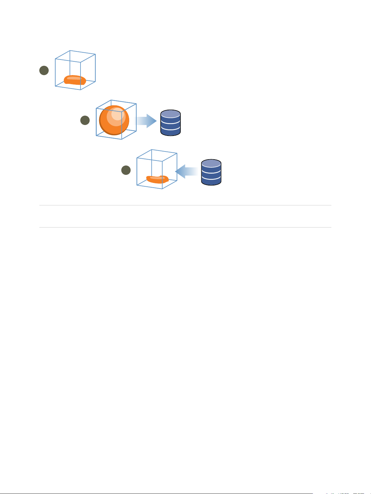
1
2
3
memory
memory
memory
swap space
swap space
vSphere Resource Management
Figure 6‑1. Memory Ballooning in the Guest Operating System
Note You must configure the guest operating system with sufficient swap space. Some guest operating
systems have additional limitations.
If necessary, you can limit the amount of memory vmmemctl reclaims by setting the
sched.mem.maxmemctl parameter for a specific virtual machine. This option specifies the maximum
amount of memory that can be reclaimed from a virtual machine in megabytes (MB). See Set Advanced
Virtual Machine Attributes.
Using Swap Files
You can specify the location of your guest swap file, reserve swap space when memory is overcommitted,
and delete a swap file.
ESXi hosts use swapping to forcibly reclaim memory from a virtual machine when the vmmemctl driver is
not available or is not responsive.
n
It was never installed.
n
It is explicitly disabled.
n
It is not running (for example, while the guest operating system is booting).
n
It is temporarily unable to reclaim memory quickly enough to satisfy current system demands.
n
It is functioning properly, but maximum balloon size is reached.
Standard demand-paging techniques swap pages back in when the virtual machine needs them.
VMware, Inc. 37
Page 38

vSphere Resource Management
Swap File Location
By default, the swap file is created in the same location as the virtual machine's configuration file, which
may either be on a VMFS datastore, a vSAN datastore or a VVol datastore. On a vSAN datastore or a
VVol datastore, the swap file is created as a separate vSAN or VVol object.
The ESXi host creates a swap file when a virtual machine is powered on. If this file cannot be created, the
virtual machine cannot power on. Instead of accepting the default, you can also:
n
Use per-virtual machine configuration options to change the datastore to another shared storage
location.
n
Use host-local swap, which allows you to specify a datastore stored locally on the host. This allows
you to swap at a per-host level, saving space on the SAN. However, it can lead to a slight
degradation in performance for vSphere vMotion because pages swapped to a local swap file on the
source host must be transferred across the network to the destination host. Currently vSAN and VVol
datastores cannot be specified for host-local swap.
Enable Host-Local Swap for a DRS Cluster
Host-local swap allows you to specify a datastore stored locally on the host as the swap file location. You
can enable host-local swap for a DRS cluster.
Procedure
1 Browse to the cluster in the vSphere Client.
2 Click Configure.
3 Under Configuration, select General to view the swap file location and click Edit to change it.
4 Select the Datastore specified by host option and click OK.
5 Browse to one of the hosts in the cluster in the vSphere Client.
6 Click Configure.
7 Under Virtual Machines, select Swap file location.
8 Click Edit and select the local datastore to use and click OK.
9 Repeat Step 5 through Step 8 for each host in the cluster.
Host-local swap is now enabled for the DRS cluster.
Enable Host-Local Swap for a Standalone Host
Host-local swap allows you to specify a datastore stored locally on the host as the swap file location. You
can enable host-local swap for a standalone host.
Procedure
1 Browse to the host in the vSphere Client.
VMware, Inc. 38
Page 39

vSphere Resource Management
2 Click Configure.
3 Under Virtual Machines, select Swap file location.
4 Click Edit and select Selected Datastore.
5 Select a local datastore from the list and click OK.
Host-local swap is now enabled for the standalone host.
Swap Space and Memory Overcommitment
You must reserve swap space for any unreserved virtual machine memory (the difference between the
reservation and the configured memory size) on per-virtual machine swap files.
This swap reservation is required to ensure that the ESXi host is able to preserve virtual machine memory
under any circumstances. In practice, only a small fraction of the host-level swap space might be used.
If you are overcommitting memory with ESXi, to support the intra-guest swapping induced by ballooning,
ensure that your guest operating systems also have sufficient swap space. This guest-level swap space
must be greater than or equal to the difference between the virtual machine’s configured memory size
and its Reservation.
Caution If memory is overcommitted, and the guest operating system is configured with insufficient
swap space, the guest operating system in the virtual machine can fail.
To prevent virtual machine failure, increase the size of the swap space in your virtual machines.
n
Windows guest operating systems— Windows operating systems refer to their swap space as paging
files. Some Windows operating systems try to increase the size of paging files automatically, if there
is sufficient free disk space.
See your Microsoft Windows documentation or search the Windows help files for “paging files.”
Follow the instructions for changing the size of the virtual memory paging file.
n
Linux guest operating system — Linux operating systems refer to their swap space as swap files. For
information on increasing swap files, see the following Linux man pages:
n
mkswap — Sets up a Linux swap area.
n
swapon — Enables devices and files for paging and swapping.
Guest operating systems with a lot of memory and small virtual disks (for example, a virtual machine with
8GB RAM and a 2GB virtual disk) are more susceptible to having insufficient swap space.
Note Do not store swap files on thin-provisioned LUNs. Running a virtual machine with a swap file that is
stored on a thin-provisioned LUN can cause swap file growth failure, which can lead to termination of the
virtual machine.
VMware, Inc. 39
Page 40

vSphere Resource Management
When you create a large swap file (for example, larger than 100GB), the amount of time it takes for the
virtual machine to power on can increase significantly. To avoid this, set a high reservation for large virtual
machines.
You can also place swap files on less costly storage using host-local swap files.
Configure Virtual Machine Swapfile Properties for the Host
Configure a swapfile location for the host to determine the default location for virtual machine swapfiles in
the vSphere Client.
By default, swapfiles for a virtual machine are located on a datastore in the folder that contains the other
virtual machine files. However, you can configure your host to place virtual machine swapfiles on an
alternative datastore.
You can use this option to place virtual machine swapfiles on lower-cost or higher-performance storage.
You can also override this host-level setting for individual virtual machines.
Setting an alternative swapfile location might cause migrations with vMotion to complete more slowly. For
best vMotion performance, store the virtual machine on a local datastore rather than in the same directory
as the virtual machine swapfiles. If the virtual machine is stored on a local datastore, storing the swapfile
with the other virtual machine files will not improve vMotion.
Prerequisites
Required privilege: Host machine.Configuration.Storage partition configuration
Procedure
1 Browse to the host in the vSphere Client.
2 Click Configure.
3 Under Virtual Machines, click Swap file location.
The selected swapfile location is displayed. If configuration of the swapfile location is not supported
on the selected host, the tab indicates that the feature is not supported.
If the host is part of a cluster, and the cluster settings specify that swapfiles are to be stored in the
same directory as the virtual machine, you cannot edit the swapfile location from the host under
Configure. To change the swapfile location for such a host, edit the cluster settings.
4 Click Edit.
5 Select where to store the swapfile.
Option Description
Virtual machine directory Stores the swapfile in the same directory as the virtual machine configuration file.
Use a specific datastore Stores the swapfile in the location you specify.
If the swapfile cannot be stored on the datastore that the host specifies, the
swapfile is stored in the same folder as the virtual machine.
6 (Optional) If you select Use a specific datastore, select a datastore from the list.
VMware, Inc. 40
Page 41

vSphere Resource Management
7 Click OK.
The virtual machine swapfile is stored in the location you selected.
Configure a Virtual Machine Swap File Location for a Cluster
By default, swap files for a virtual machine are on a datastore in the folder that contains the other virtual
machine files. However, you can instead configure the hosts in your cluster to place virtual machine swap
files on an alternative datastore of your choice.
You can configure an alternative swap file location to place virtual machine swap files on either lower-cost
or higher-performance storage, depending on your needs.
Prerequisites
Before you configure a virtual machine swap file location for a cluster, you must configure the virtual
machine swap file locations for the hosts in the cluster as described in Configure Virtual Machine Swapfile
Properties for the Host.
Procedure
1 Browse to the cluster in the vSphere Client.
2 Click Configure.
3 Select Configuration > General.
4 Next to swap file location, click Edit.
5 Select where to store the swap file.
Option Description
Virtual machine directory Stores the swap file in the same directory as the virtual machine configuration file.
Datastore specified by host Stores the swap file in the location specified in the host configuration.
If the swap file cannot be stored on the datastore that the host specifies, the swap
file is stored in the same folder as the virtual machine.
6 Click OK.
Delete Swap Files
If a host fails, and that host had running virtual machines that were using swap files, those swap files
continue to exist and consume many gigabytes of disk space. You can delete the swap files to eliminate
this problem.
Procedure
1 Restart the virtual machine that was on the host that failed.
2 Stop the virtual machine.
The swap file for the virtual machine is deleted.
VMware, Inc. 41
Page 42

vSphere Resource Management
Sharing Memory Across Virtual Machines
Many ESXi workloads present opportunities for sharing memory across virtual machines (as well as within
a single virtual machine).
ESXi memory sharing runs as a background activity that scans for sharing opportunities over time. The
amount of memory saved varies over time. For a fairly constant workload, the amount generally increases
slowly until all sharing opportunities are exploited.
To determine the effectiveness of memory sharing for a given workload, try running the workload, and use
resxtop or esxtop to observe the actual savings. Find the information in the PSHARE field of the
interactive mode in the Memory page.
Use the Mem.ShareScanTime and Mem.ShareScanGHz advanced settings to control the rate at which the
system scans memory to identify opportunities for sharing memory.
You can also configure sharing for individual virtual machines by setting the sched.mem.pshare.enable
option.
Due to security concerns, inter-virtual machine transparent page sharing is disabled by default and page
sharing is being restricted to intra-virtual machine memory sharing. This means page sharing does not
occur across virtual machines and only occurs inside of a virtual machine. The concept of salting has
been introduced to help address concerns system administrators may have over the security implications
of transparent page sharing. Salting can be used to allow more granular management of the virtual
machines participating in transparent page sharing than was previously possible. With the new salting
settings, virtual machines can share pages only if the salt value and contents of the pages are identical. A
new host config option Mem.ShareForceSalting can be configured to enable or disable salting.
See Chapter 16 Advanced Attributes for information on how to set advanced options.
Memory Compression
ESXi provides a memory compression cache to improve virtual machine performance when you use
memory overcommitment. Memory compression is enabled by default. When a host's memory becomes
overcommitted, ESXi compresses virtual pages and stores them in memory.
Because accessing compressed memory is faster than accessing memory that is swapped to disk,
memory compression in ESXi allows you to overcommit memory without significantly hindering
performance. When a virtual page needs to be swapped, ESXi first attempts to compress the page.
Pages that can be compressed to 2 KB or smaller are stored in the virtual machine's compression cache,
increasing the capacity of the host.
You can set the maximum size for the compression cache and disable memory compression using the
Advanced Settings dialog box in the vSphere Client.
VMware, Inc. 42
Page 43

vSphere Resource Management
Enable or Disable the Memory Compression Cache
Memory compression is enabled by default. You can use Advanced System Settings in the
vSphere Client to enable or disable memory compression for a host.
Procedure
1 Browse to the host in the vSphere Client.
2 Click Configure.
3 Under System, select Advanced System Settings.
4 Locate Mem.MemZipEnable and click the Edit button.
5 Enter 1 to enable or enter 0 to disable the memory compression cache.
6 Click OK.
Set the Maximum Size of the Memory Compression Cache
You can set the maximum size of the memory compression cache for the host's virtual machines.
You set the size of the compression cache as a percentage of the memory size of the virtual machine. For
example, if you enter 20 and a virtual machine's memory size is 1000 MB, ESXi can use up to 200MB of
host memory to store the compressed pages of the virtual machine.
If you do not set the size of the compression cache, ESXi uses the default value of 10 percent.
Procedure
1 Browse to the host in the vSphere Client.
2 Click Configure.
3 Under System, select Advanced System Settings.
4 Locate Mem.MemZipMaxPct and click the Edit button.
The value of this attribute determines the maximum size of the compression cache for the virtual
machine.
5 Enter the maximum size for the compression cache.
The value is a percentage of the size of the virtual machine and must be between 5 and 100 percent.
6 Click OK.
Measuring and Dierentiating Types of Memory Usage
The Performance tab of the vSphere Client displays several metrics that can be used to analyze memory
usage.
VMware, Inc. 43
Page 44

virtual machine
1
guest virtual memory
guest physical memory
machine memory
e
e
e
f
f
f
a
a
a
a
a
b
b
b
b
b
c
c
c c
c
d
d
d
virtual machine
2
vSphere Resource Management
Some of these memory metrics measure guest physical memory while other metrics measure machine
memory. For instance, two types of memory usage that you can examine using performance metrics are
guest physical memory and machine memory. You measure guest physical memory using the Memory
Granted metric (for a virtual machine) or Memory Shared (for a host). To measure machine memory,
however, use Memory Consumed (for a virtual machine) or Memory Shared Common (for a host).
Understanding the conceptual difference between these types of memory usage is important for knowing
what these metrics are measuring and how to interpret them.
The VMkernel maps guest physical memory to machine memory, but they are not always mapped one-to-
one. Multiple regions of guest physical memory might be mapped to the same region of machine memory
(when memory sharing) or specific regions of guest physical memory might not be mapped to machine
memory (when the VMkernel swaps out or balloons guest physical memory). In these situations,
calculations of guest physical memory usage and machine memory usage for an individual virtual
machine or a host differ.
Consider the example in the following figure, which shows two virtual machines running on a host. Each
block represents 4 KB of memory and each color/letter represents a different set of data on a block.
Figure 6‑2. Memory Usage Example
The performance metrics for the virtual machines can be determined as follows:
n
To determine Memory Granted (the amount of guest physical memory that is mapped to machine
memory) for virtual machine 1, count the number of blocks in virtual machine 1's guest physical
memory that have arrows to machine memory and multiply by 4 KB. Since there are five blocks with
arrows, Memory Granted is 20 KB.
n
Memory Consumed is the amount of machine memory allocated to the virtual machine, accounting for
savings from shared memory. First, count the number of blocks in machine memory that have arrows
from virtual machine 1's guest physical memory. There are three such blocks, but one block is shared
with virtual machine 2. So count two full blocks plus half of the third and multiply by 4 KB for a total of
10 KB Memory Consumed.
The important difference between these two metrics is that Memory Granted counts the number of blocks
with arrows at the guest physical memory level and Memory Consumed counts the number of blocks with
arrows at the machine memory level. The number of blocks differs between the two levels due to memory
sharing and so Memory Granted and Memory Consumed differ. Memory is being saved through sharing
or other reclamation techniques.
VMware, Inc. 44
Page 45

vSphere Resource Management
A similar result is obtained when determining Memory Shared and Memory Shared Common for the host.
n
Memory Shared for the host is the sum of each virtual machine's Memory Shared. Calculate shared
memory by looking at each virtual machine's guest physical memory and counting the number of
blocks that have arrows to machine memory blocks that themselves have more than one arrow
pointing at them. There are six such blocks in the example, so Memory Shared for the host is 24 KB.
n
Memory Shared Common is the amount of machine memory shared by virtual machines. To
determine common memory, look at the machine memory and count the number of blocks that have
more than one arrow pointing at them. There are three such blocks, so Memory Shared Common is
12 KB.
Memory Shared is concerned with guest physical memory and looks at the origin of the arrows. Memory
Shared Common, however, deals with machine memory and looks at the destination of the arrows.
The memory metrics that measure guest physical memory and machine memory might appear
contradictory. In fact, they are measuring different aspects of a virtual machine's memory usage. By
understanding the differences between these metrics, you can better use them to diagnose performance
issues.
Memory Reliability
Memory reliability, also known as error isolation, allows ESXi to stop using parts of memory when it
determines that a failure might occur, as well as when a failure did occur.
When enough corrected errors are reported at a particular address, ESXi stops using this address to
prevent the corrected error from becoming an uncorrected error.
Memory reliability provides better VMkernel reliability despite corrected and uncorrected errors in RAM. It
also enables the system to avoid using memory pages that might contain errors.
Correcting an Error Isolation Notification
With memory reliability, VMkernel stops using pages that receive an error isolation notification.
The user receives an event in the vSphere Client when VMkernel recovers from an uncorrectable memory
error, when VMkernel retires a significant percentage of system memory due to a large number of
correctable errors, or if there are a large number of pages that are unable to retire.
Procedure
1 Vacate the host.
2 Migrate the virtual machines.
3 Run memory related hardware tests.
About System Swap
System swap is a memory reclamation process that can take advantage of unused memory resources
across an entire system.
VMware, Inc. 45
Page 46

vSphere Resource Management
System swap allows the system to reclaim memory from memory consumers that are not virtual
machines. When system swap is enabled you have a tradeoff between the impact of reclaiming the
memory from another process and the ability to assign the memory to a virtual machine that can use it.
The amount of space required for the system swap is 1GB.
Memory is reclaimed by taking data out of memory and writing it to background storage. Accessing the
data from background storage is slower than accessing data from memory, so it is important to carefully
select where to store the swapped data.
ESXi determines automatically where the system swap should be stored, this is the Preferred swap file
location. This decision can be aided by selecting a certain set of options. The system selects the best
possible enabled option. If none of the options are feasible then system swap is not activated.
The available options are:
n
Datastore - Allow the use of the datastore specified. Please note that a vSAN datastore or a VVol
datastore cannot be specified for system swap files.
n
Host Swap Cache - Allow the use of part of the host swap cache.
n
Preferred swap file location - Allow the use of the preferred swap file location configured for the host.
Configure System Swap
You can customize the options that determine the system swap location.
Prerequisites
Select the Enabled check box in the Edit System Swap Settings dialog box.
Procedure
1 Browse to the host in the vSphere Client.
2 Click Configure.
3 Under System, select System Swap.
4 Click Edit.
5 Select the check boxes for each option that you want to enable.
6 If you select the datastore option, select a datastore from the drop-down menu.
7 Click OK.
VMware, Inc. 46
Page 47

Persistent Memory 7
Persistent Memory (PMem), also known as Non-Volatile Memory (NVM), is capable of maintaining data
even after a power outage. PMem can be used by applications that are sensitive to downtime and require
high performance.
VMs can be configured to use PMem on a standalone host, or in a cluster. PMem is treated as a local
datastore. Persistent memory significantly reduces storage latency. In ESXi you can create VMs that are
configured with PMem, and applications inside these VMs can take advantage of this increased speed.
Once a VM is initially powered on, PMem is reserved for it regardless of whether it is powered on or off.
This PMem stays reserved until the VM is migrated or removed.
Persistent memory can be consumed by virtual machines in two different modes. Legacy guest OSes can
still take advantage of virtual persistent memory disk feature.
n
Virtual Persistent Memory (vPMem)
Using vPMem, the memory is exposed to a guest OS as a virtual NVDIMM. This enables the guest
OS to use PMem in byte addressable random mode.
Note You must use VM hardware version 14 and a guest OS that supports NVM technology.
n
Virtual Persistent Memory Disk (vPMemDisk)
Using vPMemDisk, the memory can be accessed by the guest OS as a virtual SCSI device, but the
virtual disk is stored in a PMem datastore.
When you create a VM with PMem, memory is reserved for it at the time of Hard disk creation. Admission
control is also done at the time of Hard disk creation.
In a cluster, each VM has some capacity for PMem. The total amount of PMem must be greater than the
total amount available in the cluster. The consumption of PMem includes both powered on and powered
off VMs. If a VM is configured to use PMem and you do not use DRS, then you must manually pick a host
that has sufficient PMem to place the VM on.
NVDIMM and traditional storage
NVDIMM is accessed as memory. When you use traditional storage, software exists between applications
and storage devices which can cause a delay in processing time. When you use PMem, the applications
use the storage directly. This means that PMem performance is better than traditional storage. Storage is
local to the host. However, since system software cannot track the changes, solutions such as backups
and HA do not currently work with PMem.
VMware, Inc.
47
Page 48

vSphere Resource Management
Name spaces
Name spaces for PMem are configured before ESXi starts. Name spaces are similar to disks on the
system. ESXi reads name spaces and combines multiple name spaces into one logical volume by writing
GPT headers. This is formatted automatically by default, if you have not previously configured it. If it has
already been formatted, ESXi attempts to mount the PMem.
GPT tables
If the data in PMem storage is corrupted it can cause ESXi to fail. To avoid this, ESXi checks for errors in
the metadata during PMem mount time.
PMem regions
PMem regions are a continuous byte stream that represent a single vNVDimm or vPMemDisk. Each
PMem volume belongs to a single host. This could be difficult to manage if an administrator has to
manage each host in a cluster with a large number of hosts. However, you do not have to manage each
individual datastore. Instead you can think of the entire PMem capacity in the cluster as one datastore.
VC and DRS automate initial placement of PMem datastores. Select a local PMem storage profile when
the VM is created or when the device is added to the VM. The rest of the configuration is automated. One
limitation is that ESXi does not allow you to put the VM home on a PMem datastore. This is because it
takes up valuable space to store VM log and stat files. These regions are used to represent the VM data
and can be exposed as byte addressable nvDimms, or VpMem disks.
Migration
Since PMem is a local datastore, if you want to move a VM you must use storage vMotion. A VM with
vPMem can only be migrated to an ESX host with PMem resource. A VM with vPMemDisk can be
migrated to an ESX host without a PMem resource.
Error handling and NVDimm management
Host failures can result in a loss of availability. In the case of catastrophic errors, you may lose all data
and must take manual steps to reformat the PMem.
VMware, Inc. 48
Page 49

Configuring Virtual Graphics 8
You can edit graphics settings for supported graphics implementations.
vSphere supports multiple graphics implementations.
n
VMware supports 3d graphics solutions from AMD, Intel and NVIDIA.
n
NVIDIA GRID support.
n
Allows single NVIDIA vib to support both vSGA and vGPU implementations.
n
Provides vCenter GPU performance charts for Intel and NVIDIA.
n
Enables graphics for Horizon View VDI desktops.
You can configure host graphics settings, and customize vGPU graphics settings on a per VM basis.
Note In this chapter, "Memory" refers to physical RAM.
This chapter includes the following topics:
n
View GPU Statistics
n
Add an NVIDIA GRID vGPU to a Virtual Machine
n
Configuring Host Graphics
n
Configuring Graphics Devices
View GPU Statistics
You can view detailed information for a host graphics card.
You can see GPU temperature, utilization, and memory usage.
Note These statistics are only displayed when the GPU driver is installed on the host.
Procedure
1 In the vSphere Client, navigate to the host.
2 Click the Monitor tab and click Performance.
3 Click Advanced and select GPU from the drop-down menu.
VMware, Inc.
49
Page 50

vSphere Resource Management
Add an NVIDIA GRID vGPU to a Virtual Machine
If an ESXi host has an NVIDIA GRID GPU graphics device, you can configure a virtual machine to use
the NVIDIA GRID virtual GPU (vGPU) technology.
NVIDIA GRID GPU graphics devices are designed to optimize complex graphics operations and enable
them to run at high performance without overloading the CPU.
Prerequisites
n
Verify that an NVIDIA GRID GPU graphics device with an appropriate driver is installed on the host.
See the vSphere Upgrade documentation.
n
Verify that the virtual machine is compatible with ESXi 6.0 and later.
Procedure
1 Right-click a virtual machine and select Edit Settings.
2 On the Virtual Hardware tab, select Shared PCI Device from the drop-down menu.
3 Click Add.
4 Expand the New PCI device, and select the NVIDIA GRID vGPU passthrough device to which to
connect your virtual machine.
5 Select a GPU profile.
A GPU profile represents the vGPU type.
6 Click Reserve all memory.
7 Click OK.
The virtual machine can access the device.
Configuring Host Graphics
You can customize the graphics options on a per host basis.
Prerequisites
Virtual machines should be powered off.
Procedure
1 Select a host and select Configure > Graphics.
2 Under Host Graphics, select Edit.
VMware, Inc. 50
Page 51

vSphere Resource Management
3 In the Edit Host Graphics Settings window, select:
Option Description
Shared VMware shared virtual graphics
Shared Direct Vendor shared passthrough graphics
4 Select a shared passthrough GPU assignment policy.
a Spread VMs across GPUs (best performance)
b Group VMs on GPU until full (GPU Consolidation)
5 Click OK.
What to do next
After clicking OK, you must restart Xorg on the host.
Configuring Graphics Devices
You can edit graphics type for a video card.
Prerequisites
Virtual machines must be powered off.
Procedure
1 Under Graphics Devices, select a graphics card and click Edit.
a Select Shared for VMware shared virtual graphics.
b Select Shared Direct for Vendor shared passthrough graphics.
2 Click OK.
If you select a device, it shows which virtual machines are using that device if they are active.
What to do next
After clicking OK, you must restart Xorg on the host.
VMware, Inc. 51
Page 52

Managing Storage I/O
Resources 9
vSphere Storage I/O Control allows cluster-wide storage I/O prioritization, which allows better workload
consolidation and helps reduce extra costs associated with over provisioning.
Storage I/O Control extends the constructs of shares and limits to handle storage I/O resources. You can
control the amount of storage I/O that is allocated to virtual machines during periods of I/O congestion,
which ensures that more important virtual machines get preference over less important virtual machines
for I/O resource allocation.
When you enable Storage I/O Control on a datastore, ESXi begins to monitor the device latency that
hosts observe when communicating with that datastore. When device latency exceeds a threshold, the
datastore is considered to be congested and each virtual machine that accesses that datastore is
allocated I/O resources in proportion to their shares. You set shares per virtual machine. You can adjust
the number for each based on need.
The I/O filter framework (VAIO) allows VMware and its partners to develop filters that intercept I/O for
each VMDK and provides the desired functionality at the VMDK granularity. VAIO works along Storage
Policy-Based Management (SPBM) which allows you to set the filter preferences through a storage policy
that is attached to VMDKs.
Configuring Storage I/O Control is a two-step process:
1 Enable Storage I/O Control for the datastore.
2 Set the number of storage I/O shares and upper limit of I/O operations per second (IOPS) allowed for
each virtual machine.
By default, all virtual machine shares are set to Normal (1000) with unlimited IOPS.
Note Storage I/O Control is enabled by default on Storage DRS-enabled datastore clusters.
Note In this chapter, "Memory" refers to physical RAM.
This chapter includes the following topics:
n
About Virtual Machine Storage Policies
n
About I/O Filters
n
Storage I/O Control Requirements
VMware, Inc.
52
Page 53

vSphere Resource Management
n
Storage I/O Control Resource Shares and Limits
n
Set Storage I/O Control Resource Shares and Limits
n
Enable Storage I/O Control
n
Set Storage I/O Control Threshold Value
n
Storage DRS Integration with Storage Profiles
About Virtual Machine Storage Policies
Virtual machine storage policies are essential to virtual machine provisioning. The policies control which
type of storage is provided for the virtual machine, how the virtual machine is placed within the storage,
and which data services are offered for the virtual machine.
vSphere includes default storage policies. However, you can define and assign new policies.
You use the VM Storage Policies interface to create a storage policy. When you define the policy, you
specify various storage requirements for applications that run on virtual machines. You can also use
storage policies to request specific data services, such as caching or replication, for virtual disks.
You apply the storage policy when you create, clone, or migrate the virtual machine. After you apply the
storage policy, the Storage Policy Based Management (SPBM) mechanism places the virtual machine in
a matching datastore and, in certain storage environments, determines how the virtual machine storage
objects are provisioned and allocated within the storage resource to guarantee the required level of
service. The SPBM also enables requested data services for the virtual machine. vCenter Server
monitors policy compliance and sends an alert if the virtual machine is in breach of the assigned storage
policy.
See vSphere Storage for more information.
About I/O Filters
I/O filters that are associated with virtual disks gain direct access to the virtual machine I/O path
regardless of the underlying storage topology.
VMware offers certain categories of I/O filters. In addition, the I/O filters can be created by third-party
vendors. Typically, they are distributed as packages that provide an installer to deploy filter components
on vCenter Server and ESXi host clusters.
When I/O filters are deployed on the ESXi cluster, vCenter Server automatically configures and registers
an I/O filter storage provider, also called a VASA provider, for each host in the cluster. The storage
providers communicate with vCenter Server and make data services offered by the I/O filter visible in the
VM Storage Policies interface. You can reference these data services when defining common rules for a
VM policy. After you associate virtual disks with this policy, the I/O filters are enabled on the virtual disks.
See vSphere Storage for more information.
VMware, Inc. 53
Page 54

vSphere Resource Management
Storage I/O Control Requirements
Storage I/O Control has several requirements and limitations.
n
Datastores that are Storage I/O Control-enabled must be managed by a single vCenter Server
system.
n
Storage I/O Control is supported on Fibre Channel-connected, iSCSI-connected, and NFS-connected
storage. Raw Device Mapping (RDM) is not supported.
n
Storage I/O Control does not support datastores with multiple extents.
n
Before using Storage I/O Control on datastores that are backed by arrays with automated storage
tiering capabilities, check the VMware Storage/SAN Compatibility Guide to verify whether your
automated tiered storage array has been certified to be compatible with Storage I/O Control.
Automated storage tiering is the ability of an array (or group of arrays) to migrate LUNs/volumes or
parts of LUNs/volumes to different types of storage media (SSD, FC, SAS, SATA) based on user-set
policies and current I/O patterns. No special certification is required for arrays that do not have these
automatic migration/tiering features, including those that provide the ability to manually migrate data
between different types of storage media.
Storage I/O Control Resource Shares and Limits
You allocate the number of storage I/O shares and upper limit of I/O operations per second (IOPS)
allowed for each virtual machine. When storage I/O congestion is detected for a datastore, the I/O
workloads of the virtual machines accessing that datastore are adjusted according to the proportion of
virtual machine shares each virtual machine has.
Storage I/O shares are similar to shares used for memory and CPU resource allocation, which are
described in Resource Allocation Shares. These shares represent the relative importance of a virtual
machine regarding the distribution of storage I/O resources. Under resource contention, virtual machines
with higher share values have greater access to the storage array. When you allocate storage I/O
resources, you can limit the IOPS allowed for a virtual machine. By default, IOPS are unlimited.
The benefits and drawbacks of setting resource limits are described in Resource Allocation Limit. If the
limit you want to set for a virtual machine is in terms of MB per second instead of IOPS, you can convert
MB per second into IOPS based on the typical I/O size for that virtual machine. For example, to restrict a
back up application with 64 KB IOs to 10 MB per second, set a limit of 160 IOPS.
View Storage I/O Control Shares and Limits
You can view the shares and limits for all virtual machines running on a datastore. Viewing this
information allows you to compare the settings of all virtual machines that are accessing the datastore,
regardless of the cluster in which they are running.
Procedure
1 Browse to the datastore in the vSphere Client.
VMware, Inc. 54
Page 55

vSphere Resource Management
2 Click the VMs tab.
The tab displays each virtual machine running on the datastore and the associated shares value, and
percentage of datastore shares.
Monitor Storage I/O Control Shares
Use the datastore Performance tab to monitor how Storage I/O Control handles the I/O workloads of the
virtual machines accessing a datastore based on their shares.
Datastore performance charts allow you to monitor the following information:
n
Average latency and aggregated IOPS on the datastore
n
Latency among hosts
n
Queue depth among hosts
n
Read/write IOPS among hosts
n
Read/write latency among virtual machine disks
n
Read/write IOPS among virtual machine disks
Procedure
1 Browse to the datastore in the vSphere Client.
2 Under the Monitor tab, click Performance.
3 Select Advanced.
Set Storage I/O Control Resource Shares and Limits
Allocate storage I/O resources to virtual machines based on importance by assigning a relative amount of
shares to the virtual machine.
Unless virtual machine workloads are very similar, shares do not necessarily dictate allocation in terms of
I/O operations or megabytes per second. Higher shares allow a virtual machine to keep more concurrent
I/O operations pending at the storage device or datastore compared to a virtual machine with lower
shares. Two virtual machines might experience different throughput based on their workloads.
Prerequisites
See vSphere Storage for information on creating VM storage policies and defining common rules for VM
storage policies.
Procedure
1 Browse to the virtual machine in the vSphere Client.
a To find a virtual machine, select a data center, folder, cluster, resource pool, or host.
b Click the VMs tab.
2 Right-click the virtual machine and click Edit Settings.
VMware, Inc. 55
Page 56

vSphere Resource Management
3 Click the Virtual Hardware tab and select a virtual hard disk from the list. Expand Hard disk.
4 Select a VM storage policy from the drop-down menu.
If you select a storage policy, do not manually configure Shares and Limit - IOPS.
5 Under Shares, click the drop-down menu and select the relative amount of shares to allocate to the
virtual machine (Low, Normal, or High).
You can select Custom to enter a user-defined shares value.
6 Under Limit - IOPS, click the drop-down menu and enter the upper limit of storage resources to
allocate to the virtual machine.
IOPS are the number of I/O operations per second. By default, IOPS are unlimited. You select Low
(500), Normal (1000), or High (2000), or you can select Custom to enter a user-defined number of
shares.
7 Click OK.
Enable Storage I/O Control
When you enable Storage I/O Control, ESXi monitors datastore latency and throttles the I/O load if the
datastore average latency exceeds the threshold.
Procedure
1 Browse to the datastore in the vSphere Client.
2 Click the Configure tab.
3 Click Settings and click General.
4 Click Edit for Datastore Capabilities.
5 Select the Enable Storage I/O Control check box.
6 Click OK.
Under Datastore Capabilities, Storage I/O Control is enabled for the datastore.
Set Storage I/O Control Threshold Value
The congestion threshold value for a datastore is the upper limit of latency that is allowed for a datastore
before Storage I/O Control begins to assign importance to the virtual machine workloads according to
their shares.
You do not need to adjust the threshold setting in most environments.
Caution Storage I/O Control might not function correctly if you share the same spindles on two different
datastores.
VMware, Inc. 56
Page 57

vSphere Resource Management
If you change the congestion threshold setting, set the value based on the following considerations.
n
A higher value typically results in higher aggregate throughput and weaker isolation. Throttling will not
occur unless the overall average latency is higher than the threshold.
n
If throughput is more critical than latency, do not set the value too low. For example, for Fibre Channel
disks, a value below 20ms could lower peak disk throughput. A very high value (above 50ms) might
allow very high latency without any significant gain in overall throughput.
n
A lower value will result in lower device latency and stronger virtual machine I/O performance
isolation. Stronger isolation means that the shares controls are enforced more often. Lower device
latency translates into lower I/O latency for the virtual machines with the highest shares, at the cost of
higher I/O latency experienced by the virtual machines with fewer shares.
n
A very low value (lower than 20ms) will result in lower device latency and isolation among I/Os at the
potential cost of a decrease in aggregate datastore throughput.
n
Setting the value extremely high or extremely lowly results in poor isolation.
Prerequisites
Verify that Storage I/O Control is enabled.
Procedure
1 Browse to the datastore in the vSphere Client.
2 Click the Configure tab and click Settings.
3 Click General.
4 Click Edit for Datastore Capabilities.
5 Select the Enable Storage I/O Control check box.
Storage I/O Control automatically sets the latency threshold that corresponds to the estimated latency
when the datastore is operating at 90% of its peak throughput.
6 (Optional) Adjust the Congestion Threshold.
u
Select a value from the Percentage of peak throughput drop-down menu.
The percentage of peak throughput value indicates the estimated latency threshold when the
datastore is using that percentage of its estimated peak throughput.
u
Select a value from the Manual drop-down menu.
The value must be between 5ms and 100ms. Setting improper congestion threshold values can be
detrimental to the performance of the virtual machines on the datastore.
7 (Optional) Click Reset to defaults to restore the congestion threshold setting to the default value
(30ms).
8 Click OK.
VMware, Inc. 57
Page 58

vSphere Resource Management
Storage DRS Integration with Storage Profiles
Storage Policy Based Management (SPBM) allows you to specify the policy for a virtual machine which is
enforced by Storage DRS. A datastore cluster can have set of datastores with different capability profiles.
If the virtual machines have storage profiles associated with them, Storage DRS can enforce placement
based on underlying datastore capabilities.
As part of Storage DRS integration with storage profiles, the Storage DRS cluster level advanced option
EnforceStorageProfiles is introduced. Advanced option EnforceStorageProfiles takes one of
these integer values: 0,1 or 2. The default value is 0. When the option is set to 0, it indicates that there is
no storage profile or policy enforcement on the Storage DRS cluster. When the option is set to 1, it
indicates that there is a storage profile or policy soft enforcement on the Storage DRS cluster. This is
analogous with DRS soft rules. Storage DRS will comply with storage profile or policy in the optimum
level. Storage DRS will violate the storage profile compliant if it is required to do so. Storage DRS affinity
rules will have higher precedence over storage profiles only when storage profile enforcement is set to 1.
When the option is set to 2, it indicates that there is a storage profile or policy hard enforcement on the
Storage DRS cluster. This is analogous with DRS hard rules. Storage DRS will not violate the storage
profile or policy compliant. Storage profiles will have higher precedence over affinity rules. Storage DRS
will generate fault: could not fix anti-affinity rule violation
Prerequisites
By default, Storage DRS will not enforce storage policies associated with a virtual machine. Please
configure EnforceStorageProfiles option according to your requirements. The options are Default (0),
Soft (1) or Hard (2).
Procedure
1 Log in to the vSphere Client as an Administrator.
2 In the vSphere Client, click on the Storage DRS cluster, then select Manage > Settings > Storage
DRS.
3 Click Edit > Advanced Options > Configuration parameters and select Add.
4 Click in the area under the Option heading and type EnforceStorageProfiles
5 Click in the area under the Value heading to the right of the previously entered advanced option name
and type the value of either 0, 1 or 2.
6 Click OK.
VMware, Inc. 58
Page 59

Managing Resource Pools 10
root resource pool
siblings
siblings
parent resource pool
child resource pool
A resource pool is a logical abstraction for flexible management of resources. Resource pools can be
grouped into hierarchies and used to hierarchically partition available CPU and memory resources.
Each standalone host and each DRS cluster has an (invisible) root resource pool that groups the
resources of that host or cluster. The root resource pool does not appear because the resources of the
host (or cluster) and the root resource pool are always the same.
Users can create child resource pools of the root resource pool or of any user-created child resource
pool. Each child resource pool owns some of the parent’s resources and can, in turn, have a hierarchy of
child resource pools to represent successively smaller units of computational capability.
A resource pool can contain child resource pools, virtual machines, or both. You can create a hierarchy of
shared resources. The resource pools at a higher level are called parent resource pools. Resource pools
and virtual machines that are at the same level are called siblings. The cluster itself represents the root
resource pool. If you do not create child resource pools, only the root resource pools exist.
In the following example, RP-QA is the parent resource pool for RP-QA-UI. RP-Marketing and RP-QA are
siblings. The three virtual machines immediately below RP-Marketing are also siblings.
Figure 10‑1. Parents, Children, and Siblings in Resource Pool Hierarchy
For each resource pool, you specify reservation, limit, shares, and whether the reservation should be
expandable. The resource pool resources are then available to child resource pools and virtual machines.
Note In this chapter, "Memory" refers to physical RAM.
This chapter includes the following topics:
n
Why Use Resource Pools?
n
Create a Resource Pool
n
Edit a Resource Pool
VMware, Inc.
59
Page 60

vSphere Resource Management
n
Add a Virtual Machine to a Resource Pool
n
Remove a Virtual Machine from a Resource Pool
n
Remove a Resource Pool
n
Resource Pool Admission Control
Why Use Resource Pools?
Resource pools allow you to delegate control over resources of a host (or a cluster), but the benefits are
evident when you use resource pools to compartmentalize all resources in a cluster. Create multiple
resource pools as direct children of the host or cluster and configure them. You can then delegate control
over the resource pools to other individuals or organizations.
Using resource pools can result in the following benefits.
n
Flexible hierarchical organization—Add, remove, or reorganize resource pools or change resource
allocations as needed.
n
Isolation between pools, sharing within pools—Top-level administrators can make a pool of resources
available to a department-level administrator. Allocation changes that are internal to one departmental
resource pool do not unfairly affect other unrelated resource pools.
n
Access control and delegation—When a top-level administrator makes a resource pool available to a
department-level administrator, that administrator can then perform all virtual machine creation and
management within the boundaries of the resources to which the resource pool is entitled by the
current shares, reservation, and limit settings. Delegation is usually done in conjunction with
permissions settings.
n
Separation of resources from hardware—If you are using clusters enabled for DRS, the resources of
all hosts are always assigned to the cluster. That means administrators can perform resource
management independently of the actual hosts that contribute to the resources. If you replace three
2GB hosts with two 3GB hosts, you do not need to make changes to your resource allocations.
This separation allows administrators to think more about aggregate computing capacity and less
about individual hosts.
n
Management of sets of virtual machines running a multitier service— Group virtual machines for a
multitier service in a resource pool. You do not need to set resources on each virtual machine.
Instead, you can control the aggregate allocation of resources to the set of virtual machines by
changing settings on their enclosing resource pool.
For example, assume a host has a number of virtual machines. The marketing department uses three of
the virtual machines and the QA department uses two virtual machines. Because the QA department
needs larger amounts of CPU and memory, the administrator creates one resource pool for each group.
The administrator sets CPU Shares to High for the QA department pool and to Normal for the Marketing
department pool so that the QA department users can run automated tests. The second resource pool
with fewer CPU and memory resources is sufficient for the lighter load of the marketing staff. Whenever
the QA department is not fully using its allocation, the marketing department can use the available
resources.
VMware, Inc. 60
Page 61

vSphere Resource Management
The numbers in the following figure show the effective allocations to the resource pools.
VMware, Inc. 61
Page 62

Host
6GHz, 6GB
RP-QA
4GHz, 4GB
QA 1 QA 2 Marketing 1 Marketing 2 Marketing 3
RP-Marketing
2GHz, 2GB
vSphere Resource Management
Figure 10‑2. Allocating Resources to Resource Pools
VMware, Inc. 62
Page 63

vSphere Resource Management
Create a Resource Pool
You can create a child resource pool of any ESXi host, resource pool, or DRS cluster.
Note If a host has been added to a cluster, you cannot create child resource pools of that host. If the
cluster is enabled for DRS, you can create child resource pools of the cluster.
When you create a child resource pool, you are prompted for resource pool attribute information. The
system uses admission control to make sure you cannot allocate resources that are not available.
Prerequisites
The vSphere Client is connected to the vCenter Server system.
Procedure
1 In the vSphere Client, select a parent object for the resource pool (a host, another resource pool, or a
DRS cluster).
2 Right-click the object and select New Resource Pool.
3 Type a name to identify the resource pool.
4 Specify how to allocate CPU and memory resources.
The CPU resources for your resource pool are the guaranteed physical resources the host reserves
for a resource pool. Normally, you accept the default and let the host handle resource allocation.
Option Description
Shares Specify shares for this resource pool with respect to the parent’s total resources.
Sibling resource pools share resources according to their relative share values
bounded by the reservation and limit.
n
Select Low, Normal, or High to specify share values respectively in a 1:2:4
ratio.
n
Select Custom to give each virtual machine a specific number of shares,
which expresses a proportional weight.
Reservation Specify a guaranteed CPU or memory allocation for this resource pool. Defaults
to 0.
A nonzero reservation is subtracted from the unreserved resources of the parent
(host or resource pool). The resources are considered reserved, regardless of
whether virtual machines are associated with the resource pool.
Expandable Reservation When the check box is selected (default), expandable reservations are
considered during admission control.
If you power on a virtual machine in this resource pool, and the combined
reservations of the virtual machines are larger than the reservation of the
resource pool, the resource pool can use resources from its parent or ancestors.
Limit Specify the upper limit for this resource pool’s CPU or memory allocation. You can
usually accept the default (Unlimited).
To specify a limit, deselect the Unlimited check box.
5 Click OK.
VMware, Inc. 63
Page 64

vSphere Resource Management
After you create a resource pool, you can add virtual machines to it. A virtual machine’s shares are
relative to other virtual machines (or resource pools) with the same parent resource pool.
Example: Creating Resource Pools
Assume that you have a host that provides 6GHz of CPU and 3GB of memory that must be shared
between your marketing and QA departments. You also want to share the resources unevenly, giving one
department (QA) a higher priority. This can be accomplished by creating a resource pool for each
department and using the Shares attribute to prioritize the allocation of resources.
The example shows how to create a resource pool with the ESXi host as the parent resource.
1 In the New Resource Pool dialog box, type a name for the QA department’s resource pool (for
example, RP-QA).
2 Specify Shares of High for the CPU and memory resources of RP-QA.
3 Create a second resource pool, RP-Marketing.
Leave Shares at Normal for CPU and memory.
4 Click OK.
If there is resource contention, RP-QA receives 4GHz and 2GB of memory, and RP-Marketing 2GHz and
1GB. Otherwise, they can receive more than this allotment. Those resources are then available to the
virtual machines in the respective resource pools.
Edit a Resource Pool
After you create the resource pool, you can edit its CPU and memory resource settings.
Procedure
1 Browse to the resource pool in the vSphere Client.
2 Select Edit Resource Settings from the Actions drop-down menu.
3 (Optional) You can change all attributes of the selected resource pool as described in Create a
Resource Pool.
u
Under CPU, select CPU resource settings.
u
Under Memory, select memory resource settings.
4 Click OK to save your changes.
Add a Virtual Machine to a Resource Pool
When you create a virtual machine, you can specify a resource pool location as part of the creation
process. You can also add an existing virtual machine to a resource pool.
When you move a virtual machine to a new resource pool:
n
The virtual machine’s reservation and limit do not change.
VMware, Inc. 64
Page 65

vSphere Resource Management
n
If the virtual machine’s shares are high, medium, or low, %Shares adjusts to reflect the total number
of shares in use in the new resource pool.
n
If the virtual machine has custom shares assigned, the share value is maintained.
Note Because share allocations are relative to a resource pool, you might have to manually change
a virtual machine’s shares when you move it into a resource pool so that the virtual machine’s shares
are consistent with the relative values in the new resource pool. A warning appears if a virtual
machine would receive a very large (or very small) percentage of total shares.
n
Under Monitor, the information displayed in the Resource Reservation tab about the resource
pool’s reserved and unreserved CPU and memory resources changes to reflect the reservations
associated with the virtual machine (if any).
Note If a virtual machine has been powered off or suspended, it can be moved but overall available
resources (such as reserved and unreserved CPU and memory) for the resource pool are not
affected.
Procedure
1 Browse to the virtual machine in the vSphere Client.
a To find a virtual machine, select a data center, folder, cluster, resource pool, or host.
b Click the VMs tab.
2 Right-click the virtual machine and click Migrate.
n
You can move the virtual machine to another host.
n
You can move the virtual machine's storage to another datastore.
n
You can move the virtual machine to another host and move its storage to another datastore.
3 Select a resource pool in which to run the virtual machine.
4 Review your selections and click Finish.
If a virtual machine is powered on, and the destination resource pool does not have enough CPU or
memory to guarantee the virtual machine’s reservation, the move fails because admission control does
not allow it. An error dialog box displays available and requested resources, so you can consider whether
an adjustment might resolve the issue.
Remove a Virtual Machine from a Resource Pool
You can remove a virtual machine from a resource pool either by moving the virtual machine to another
resource pool or deleting it.
VMware, Inc. 65
Page 66

vSphere Resource Management
When you remove a virtual machine from a resource pool, the total number of shares associated with the
resource pool decreases, so that each remaining share represents more resources. For example,
assume you have a pool that is entitled to 6GHz, containing three virtual machines with shares set to
Normal. Assuming the virtual machines are CPU-bound, each gets an equal allocation of 2GHz. If one of
the virtual machines is moved to a different resource pool, the two remaining virtual machines each
receive an equal allocation of 3GHz.
Procedure
1 Browse to the resource pool in the vSphere Client.
2 Choose one of the following methods to remove the virtual machine from a resource pool.
n
Right-click the virtual machine and select Move To... to move the virtual machine to another
resource pool.
You do not need to power off the virtual machine before you move it.
n
Right-click the virtual machine and select Delete from Disk.
You must power off the virtual machine before you can completely remove it.
Remove a Resource Pool
You can remove a resource pool from the inventory.
Procedure
1 In the vSphere Client, right-click the resource pool and Select Delete.
A confirmation dialog box appears.
2 Click Yes to remove the resource pool.
Resource Pool Admission Control
When you power on a virtual machine in a resource pool, or try to create a child resource pool, the
system performs additional admission control to ensure the resource pool’s restrictions are not violated.
Before you power on a virtual machine or create a resource pool, ensure that sufficient resources are
available using the Resource Reservation tab in the vSphere Client. The Available Reservation value
for CPU and memory displays resources that are unreserved.
How available CPU and memory resources are computed and whether actions are performed depends
on the Reservation Type.
VMware, Inc. 66
Page 67

vSphere Resource Management
Table 10‑1. Reservation Types
Reservation Type Description
Fixed The system checks whether the selected resource pool has sufficient unreserved resources. If
it does, the action can be performed. If it does not, a message appears and the action cannot
be performed.
Expandable
(default)
The system considers the resources available in the selected resource pool and its direct
parent resource pool. If the parent resource pool also has the Expandable Reservation
option selected, it can borrow resources from its parent resource pool. Borrowing resources
occurs recursively from the ancestors of the current resource pool as long as the Expandable
Reservation option is selected. Leaving this option selected offers more flexibility, but, at the
same time provides less protection. A child resource pool owner might reserve more resources
than you anticipate.
The system does not allow you to violate preconfigured Reservation or Limit settings. Each time you
reconfigure a resource pool or power on a virtual machine, the system validates all parameters so all
service-level guarantees can still be met.
Expandable Reservations Example 1
This example shows you how a resource pool with expandable reservations works.
Assume an administrator manages pool P, and defines two child resource pools, S1 and S2, for two
different users (or groups).
The administrator knows that users want to power on virtual machines with reservations, but does not
know how much each user will need to reserve. Making the reservations for S1 and S2 expandable
allows the administrator to more flexibly share and inherit the common reservation for pool P.
Without expandable reservations, the administrator needs to explicitly allocate S1 and S2 a specific
amount. Such specific allocations can be inflexible, especially in deep resource pool hierarchies and can
complicate setting reservations in the resource pool hierarchy.
Expandable reservations cause a loss of strict isolation. S1 can start using all of P's reservation, so that
no memory or CPU is directly available to S2.
Expandable Reservations Example 2
This example shows how a resource pool with expandable reservations works.
Assume the following scenario, as shown in the figure.
n
Parent pool RP-MOM has a reservation of 6GHz and one running virtual machine VM-M1 that
reserves 1GHz.
n
You create a child resource pool RP-KID with a reservation of 2GHz and with Expandable
Reservation selected.
n
You add two virtual machines, VM-K1 and VM-K2, with reservations of 2GHz each to the child
resource pool and try to power them on.
n
VM-K1 can reserve the resources directly from RP-KID (which has 2GHz).
VMware, Inc. 67
Page 68
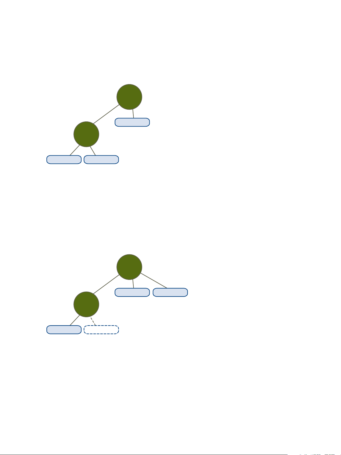
VM-K1, 2GHz VM-K2, 2GHz
2GHz
6GHz
RP-KID
VM-M1, 1GHz
RP-MOM
VM-K1, 2GHz VM-K2, 2GHz
2GHz
6GHz
RP-KID
VM-M1, 1GHz VM-M2, 2GHz
RP-MOM
vSphere Resource Management
n
No local resources are available for VM-K2, so it borrows resources from the parent resource pool,
RP-MOM. RP-MOM has 6GHz minus 1GHz (reserved by the virtual machine) minus 2GHz (reserved
by RP-KID), which leaves 3GHz unreserved. With 3GHz available, you can power on the 2GHz virtual
machine.
Figure 10‑3. Admission Control with Expandable Resource Pools: Successful Power-On
Now, consider another scenario with VM-M1 and VM-M2.
n
Power on two virtual machines in RP-MOM with a total reservation of 3GHz.
n
You can still power on VM-K1 in RP-KID because 2GHz are available locally.
n
When you try to power on VM-K2, RP-KID has no unreserved CPU capacity so it checks its parent.
RP-MOM has only 1GHz of unreserved capacity available (5GHz of RP-MOM are already in use—
3GHz reserved by the local virtual machines and 2GHz reserved by RP-KID). As a result, you cannot
power on VM-K2, which requires a 2GHz reservation.
Figure 10‑4. Admission Control with Expandable Resource Pools: Power-On Prevented
VMware, Inc. 68
Page 69

Creating a DRS Cluster 11
A cluster is a collection of ESXi hosts and associated virtual machines with shared resources and a
shared management interface. Before you can obtain the benefits of cluster-level resource management
you must create a cluster and enable DRS.
Depending on whether or not Enhanced vMotion Compatibility (EVC) is enabled, DRS behaves differently
when you use vSphere Fault Tolerance (vSphere FT) virtual machines in your cluster.
Table 11‑1. DRS Behavior with vSphere FT Virtual Machines and EVC
EVC DRS (Load Balancing) DRS (Initial Placement)
Enabled Enabled (Primary and Secondary VMs) Enabled (Primary and Secondary VMs)
Disabled Disabled (Primary and Secondary VMs) Disabled (Primary VMs)
Fully Automated (Secondary VMs)
This chapter includes the following topics:
n
Admission Control and Initial Placement
n
Virtual Machine Migration
n
DRS Cluster Requirements
n
Configuring DRS with Virtual Flash
n
Create a Cluster
n
Edit Cluster Settings
n
Set a Custom Automation Level for a Virtual Machine
n
Disable DRS
n
Restore a Resource Pool Tree
Admission Control and Initial Placement
When you attempt to power on a single virtual machine or a group of virtual machines in a DRS-enabled
cluster, vCenter Server performs admission control. It checks that there are enough resources in the
cluster to support the virtual machine(s).
VMware, Inc.
69
Page 70

vSphere Resource Management
If the cluster does not have sufficient resources to power on a single virtual machine, or any of the virtual
machines in a group power-on attempt, a message appears. Otherwise, for each virtual machine, DRS
generates a recommendation of a host on which to run the virtual machine and takes one of the following
actions
n
Automatically executes the placement recommendation.
n
Displays the placement recommendation, which the user can then choose to accept or override.
Note No initial placement recommendations are given for virtual machines on standalone hosts or in
non-DRS clusters. When powered on, they are placed on the host where they currently reside.
n
DRS considers network bandwidth. By calculating host network saturation, DRS is able to make
better placement decisions. This can help avoid performance degradation of virtual machines with a
more comprehensive understanding of the environment.
Single Virtual Machine Power On
In a DRS cluster, you can power on a single virtual machine and receive initial placement
recommendations.
When you power on a single virtual machine, you have two types of initial placement recommendations:
n
A single virtual machine is being powered on and no prerequisite steps are needed.
The user is presented with a list of mutually exclusive initial placement recommendations for the
virtual machine. You can select only one.
n
A single virtual machine is being powered on, but prerequisite actions are required.
These actions include powering on a host in standby mode or the migration of other virtual machines
from one host to another. In this case, the recommendations provided have multiple lines, showing
each of the prerequisite actions. The user can either accept this entire recommendation or cancel
powering on the virtual machine.
Group Power-on
You can attempt to power on multiple virtual machines at the same time (group power-on).
Virtual machines selected for a group power-on attempt do not have to be in the same DRS cluster. They
can be selected across clusters but must be within the same data center. It is also possible to include
virtual machines located in non-DRS clusters or on standalone hosts. These virtual machines are
powered on automatically and not included in any initial placement recommendation.
The initial placement recommendations for group power-on attempts are provided on a per-cluster basis.
If all the placement-related actions for a group power-on attempt are in automatic mode, the virtual
machines are powered on with no initial placement recommendation given. If placement-related actions
for any of the virtual machines are in manual mode, the powering on of all the virtual machines (including
the virtual machines that are in automatic mode) is manual. These actions are included in an initial
placement recommendation.
VMware, Inc. 70
Page 71

vSphere Resource Management
For each DRS cluster that the virtual machines being powered on belong to, there is a single
recommendation, which contains all the prerequisites (or no recommendation). All such cluster-specific
recommendations are presented together under the Power On Recommendations tab.
When a nonautomatic group power-on attempt is made, and virtual machines not subject to an initial
placement recommendation (that is, the virtual machines on standalone hosts or in non-DRS clusters) are
included, vCenter Server attempts to power them on automatically. If these power-ons are successful,
they are listed under the Started Power-Ons tab. Any virtual machines that fail to power-on are listed
under the Failed Power-Ons tab.
Example: Group Power-on
The user selects three virtual machines in the same data center for a group power-on attempt. The first
two virtual machines (VM1 and VM2) are in the same DRS cluster (Cluster1), while the third virtual
machine (VM3) is on a standalone host. VM1 is in automatic mode and VM2 is in manual mode. For this
scenario, the user is presented with an initial placement recommendation for Cluster1 (under the Power
On Recommendations tab) which consists of actions for powering on VM1 and VM2. An attempt is
made to power on VM3 automatically and, if successful, it is listed under the Started Power-Ons tab. If
this attempt fails, it is listed under the Failed Power-Ons tab.
Virtual Machine Migration
Although DRS performs initial placements so that load is balanced across the cluster, changes in virtual
machine load and resource availability can cause the cluster to become unbalanced. To correct such
imbalances, DRS generates migration recommendations.
If DRS is enabled on the cluster, load can be distributed more uniformly to reduce the degree of this
imbalance. For example, the three hosts on the left side of the following figure are unbalanced. Assume
that Host 1, Host 2, and Host 3 have identical capacity, and all virtual machines have the same
configuration and load (which includes reservation, if set). However, because Host 1 has six virtual
machines, its resources might be overused while ample resources are available on Host 2 and Host 3.
DRS migrates (or recommends the migration of) virtual machines from Host 1 to Host 2 and Host 3. On
the right side of the diagram, the properly load balanced configuration of the hosts that results appears.
VMware, Inc. 71
Page 72

Host 1
VM1
VM4
VM2 VM3
VM5 VM6
Host 2
VM7
Host 3
VM8 VM9
Host 1
VM1 VM2 VM3
Host 2
VM7 VM4 VM5
Host 3
VM8 VM9 VM6
vSphere Resource Management
Figure 11‑1. Load Balancing
When a cluster becomes unbalanced, DRS makes recommendations or migrates virtual machines,
depending on the default automation level:
n
If the cluster or any of the virtual machines involved are manual or partially automated,
vCenter Server does not take automatic actions to balance resources. Instead, the Summary page
indicates that migration recommendations are available and the DRS Recommendations page
displays recommendations for changes that make the most efficient use of resources across the
cluster.
n
If the cluster and virtual machines involved are all fully automated, vCenter Server migrates running
virtual machines between hosts as needed to ensure efficient use of cluster resources.
Note Even in an automatic migration setup, users can explicitly migrate individual virtual machines,
but vCenter Server might move those virtual machines to other hosts to optimize cluster resources.
By default, automation level is specified for the whole cluster. You can also specify a custom automation
level for individual virtual machines.
DRS Migration Threshold
The DRS migration threshold allows you to specify which recommendations are generated and then
applied (when the virtual machines involved in the recommendation are in fully automated mode) or
shown (if in manual mode). This threshold is also a measure of how much cluster imbalance across host
(CPU and memory) loads is acceptable.
VMware, Inc. 72
Page 73

vSphere Resource Management
You can move the threshold slider to use one of five settings, ranging from Conservative to Aggressive.
The five migration settings generate recommendations based on their assigned priority level. Each setting
you move the slider to the right allows the inclusion of one more lower level of priority. The Conservative
setting generates only priority-one recommendations (mandatory recommendations), the next level to the
right generates priority-two recommendations and higher, and so on, down to the Aggressive level which
generates priority-five recommendations and higher (that is, all recommendations.)
A priority level for each migration recommendation is computed using the load imbalance metric of the
cluster. This metric is displayed as Current host load standard deviation in the cluster's Summary tab in
the vSphere Client. A higher load imbalance leads to higher-priority migration recommendations. For
more information about this metric and how a recommendation priority level is calculated, see the
VMware Knowledge Base article "Calculating the priority level of a VMware DRS migration
recommendation."
After a recommendation receives a priority level, this level is compared to the migration threshold you set.
If the priority level is less than or equal to the threshold setting, the recommendation is either applied (if
the relevant virtual machines are in fully automated mode) or displayed to the user for confirmation (if in
manual or partially automated mode.)
Migration Recommendations
If you create a cluster with a default manual or partially automated mode, vCenter Server displays
migration recommendations on the DRS Recommendations page.
The system supplies as many recommendations as necessary to enforce rules and balance the
resources of the cluster. Each recommendation includes the virtual machine to be moved, current
(source) host and destination host, and a reason for the recommendation. The reason can be one of the
following:
n
Balance average CPU loads or reservations.
n
Balance average memory loads or reservations.
n
Satisfy resource pool reservations.
n
Satisfy an affinity rule.
n
Host is entering maintenance mode or standby mode.
Note If you are using the vSphere Distributed Power Management (DPM) feature, in addition to
migration recommendations, DRS provides host power state recommendations.
DRS Cluster Requirements
Hosts that are added to a DRS cluster must meet certain requirements to use cluster features
successfully.
Shared Storage Requirements
A DRS cluster has certain shared storage requirements.
VMware, Inc. 73
Page 74

vSphere Resource Management
Ensure that the managed hosts use shared storage. Shared storage is typically on a SAN, but can also
be implemented using NAS shared storage.
See the vSphere Storage documentation for information about other shared storage.
Shared VMFS Volume Requirements
A DRS cluster has certain shared VMFS volume requirements.
Configure all managed hosts to use shared VMFS volumes.
n
Place the disks of all virtual machines on VMFS volumes that are accessible by source and
destination hosts.
n
Ensure the VMFS volume is sufficiently large to store all virtual disks for your virtual machines.
n
Ensure all VMFS volumes on source and destination hosts use volume names, and all virtual
machines use those volume names for specifying the virtual disks.
Note Virtual machine swap files also need to be on a VMFS accessible to source and destination hosts
(just like .vmdk virtual disk files). This requirement does not apply if all source and destination hosts are
ESX Server 3.5 or higher and using host-local swap. In that case, vMotion with swap files on unshared
storage is supported. Swap files are placed on a VMFS by default, but administrators might override the
file location using advanced virtual machine configuration options.
Processor Compatibility Requirements
A DRS cluster has certain processor compatibility requirements.
To avoid limiting the capabilities of DRS, you should maximize the processor compatibility of source and
destination hosts in the cluster.
vMotion transfers the running architectural state of a virtual machine between underlying ESXi hosts.
vMotion compatibility means that the processors of the destination host must be able to resume execution
using the equivalent instructions where the processors of the source host were suspended. Processor
clock speeds and cache sizes might vary, but processors must come from the same vendor class (Intel
versus AMD) and the same processor family to be compatible for migration with vMotion.
Processor families are defined by the processor vendors. You can distinguish different processor versions
within the same family by comparing the processors’ model, stepping level, and extended features.
Sometimes, processor vendors have introduced significant architectural changes within the same
processor family (such as 64-bit extensions and SSE3). VMware identifies these exceptions if it cannot
guarantee successful migration with vMotion.
VMware, Inc. 74
Page 75

vSphere Resource Management
vCenter Server provides features that help ensure that virtual machines migrated with vMotion meet
processor compatibility requirements. These features include:
n
Enhanced vMotion Compatibility (EVC) – You can use EVC to help ensure vMotion compatibility for
the hosts in a cluster. EVC ensures that all hosts in a cluster present the same CPU feature set to
virtual machines, even if the actual CPUs on the hosts differ. This prevents migrations with vMotion
from failing due to incompatible CPUs.
Configure EVC from the Cluster Settings dialog box. The hosts in a cluster must meet certain
requirements for the cluster to use EVC. For information about EVC and EVC requirements, see the
vCenter Server and Host Management documentation.
n
CPU compatibility masks – vCenter Server compares the CPU features available to a virtual machine
with the CPU features of the destination host to determine whether to allow or disallow migrations
with vMotion. By applying CPU compatibility masks to individual virtual machines, you can hide
certain CPU features from the virtual machine and potentially prevent migrations with vMotion from
failing due to incompatible CPUs.
vMotion Requirements for DRS Clusters
A DRS cluster has certain vMotion requirements.
To enable the use of DRS migration recommendations, the hosts in your cluster must be part of a vMotion
network. If the hosts are not in the vMotion network, DRS can still make initial placement
recommendations.
To be configured for vMotion, each host in the cluster must meet the following requirements:
n
vMotion does not support raw disks or migration of applications clustered using Microsoft Cluster
Service (MSCS).
n
vMotion requires a private Gigabit Ethernet migration network between all of the vMotion enabled
managed hosts. When vMotion is enabled on a managed host, configure a unique network identity
object for the managed host and connect it to the private migration network.
Configuring DRS with Virtual Flash
DRS can manage virtual machines that have virtual flash reservations.
Virtual flash capacity appears as a statistic that is regularly reported from the host to the vSphere Client.
Each time DRS runs, it uses the most recent capacity value reported.
You can configure one virtual flash resource per host. This means that during virtual machine power-on
time, DRS does not need to select between different virtual flash resources on a given host.
DRS selects a host that has sufficient available virtual flash capacity to start the virtual machine. If DRS
cannot satisfy the virtual flash reservation of a virtual machine, it cannot be powered-on. DRS treats a
powered-on virtual machine with a virtual flash reservation as having a soft affinity with its current host.
DRS will not recommend such a virtual machine for vMotion except for mandatory reasons, such as
putting a host in maintenance mode, or to reduce the load on an over utilized host.
VMware, Inc. 75
Page 76

vSphere Resource Management
Create a Cluster
A cluster is a group of hosts. When a host is added to a cluster, the host's resources become part of the
cluster's resources. The cluster manages the resources of all hosts within it. Clusters enable the vSphere
High Availability (HA) and vSphere Distributed Resource Scheduler (DRS) solutions.
Prerequisites
n
Verify that you have sufficient permissions to create a cluster object.
n
Verify that a data center exists in the inventory.
Procedure
1 Browse to a data center in the vSphere Client.
2 Right-click the data center and select New Cluster.
3 Enter a name for the cluster.
4 Select DRS and vSphere HA cluster features.
Option Description
To use DRS with this cluster a Select the DRS Turn ON check box.
b Select an automation level and a migration threshold.
To use HA with this cluster a Select the vSphere HA Turn ON check box.
b Select whether to enable host monitoring and admission control.
c If admission control is enabled, specify a policy.
d Select a VM Monitoring option.
e Specify the virtual machine monitoring sensitivity.
5 Select an Enhanced vMotion Compatibility (EVC) setting.
EVC ensures that all hosts in a cluster present the same CPU feature set to virtual machines, even if
the actual CPUs on the hosts differ. This prevents migrations with vMotion from failing due to
incompatible CPUs.
6 Click OK.
The cluster is added to the inventory.
What to do next
Add hosts and resource pools to the cluster.
Edit Cluster Settings
When you add a host to a DRS cluster, the host’s resources become part of the cluster’s resources. In
addition to this aggregation of resources, with a DRS cluster you can support cluster-wide resource pools
and enforce cluster-level resource allocation policies.
VMware, Inc. 76
Page 77

vSphere Resource Management
The following cluster-level resource management capabilities are also available.
Load Balancing The distribution and usage of CPU and memory resources for all hosts and
virtual machines in the cluster are continuously monitored. DRS compares
these metrics to an ideal resource usage given the attributes of the cluster’s
resource pools and virtual machines, the current demand, and the
imbalance target. DRS then provides recommendations or performs virtual
machine migrations accordingly. See Virtual Machine Migration. When you
power on a virtual machine in the cluster, DRS attempts to maintain proper
load balancing by either placing the virtual machine on an appropriate host
or making a recommendation. See Admission Control and Initial
Placement.
Power management When the vSphere Distributed Power Management (DPM) feature is
enabled, DRS compares cluster and host-level capacity to the demands of
the cluster’s virtual machines, including recent historical demand. DRS then
recommends you place hosts in standby, or places hosts in standby power
mode when sufficient excess capacity is found. DRS powers-on hosts if
capacity is needed. Depending on the resulting host power state
recommendations, virtual machines might need to be migrated to and from
the hosts as well. See Managing Power Resources.
Affinity Rules You can control the placement of virtual machines on hosts within a cluster,
by assigning affinity rules. See Using DRS Affinity Rules.
Prerequisites
You can create a cluster without a special license, but you must have a license to enable a cluster for
vSphere DRS (or vSphere HA).
Procedure
1 Browse to a cluster in the vSphere Client.
2 Click the Configure tab and click Services.
3 Under vSphere DRS click Edit.
4 Under DRS Automation, select a default automation level for DRS.
Automation Level Action
Manual
Partially Automated
Fully Automated
n
Initial placement: Recommended host is displayed.
n
Migration: Recommendation is displayed.
n
Initial placement: Automatic.
n
Migration: Recommendation is displayed.
n
Initial placement: Automatic.
n
Migration: Recommendation is run automatically.
5 Set the Migration Threshold for DRS.
VMware, Inc. 77
Page 78

vSphere Resource Management
6 Select the Predictive DRS check box. In addition to real-time metrics, DRS responds to forecasted
metrics provided by vRealize Operations server. You must also configure Predictive DRS in a version
of vRealize Operations that supports this feature.
7 Select Virtual Machine Automation check box to enable individual virtual machine automation
levels.
Override for individual virtual machines can be set from the VM Overrides page.
8 Under Additional Options, select a check box to enforce one of the default policies.
Option Description
VM Distribution For availability, distribute a more even number of virtual machines across hosts.
This is secondary to DRS load balancing.
Memory Metric for Load Balancing Load balance based on consumed memory of virtual machines rather than active
memory. This setting is only recommended for clusters where host memory is not
over-committed.
CPU Over-Commitment Control CPU over-commitment in the cluster.
9 Under Power Management, select Automation Level.
10 If DPM is enabled, set the DPM Threshold.
11 Click OK.
Set a Custom Automation Level for a Virtual Machine
After you create a DRS cluster, you can customize the automation level for individual virtual machines to
override the cluster’s default automation level.
For example, you can select Manual for specific virtual machines in a cluster with full automation, or
Partially Automated for specific virtual machines in a manual cluster.
If a virtual machine is set to Disabled, vCenter Server does not migrate that virtual machine or provide
migration recommendations for it. This is known as pinning the virtual machine to its registered host.
Procedure
1 Browse to the cluster in the vSphere Client.
2 Click the Configure tab and click Services.
3 Under Services, select vSphere DRS and click Edit. Expand DRS Automation.
4 Select the Enable individual virtual machine automation levels check box.
5 To temporarily disable any individual virtual machine overrides, deselect the Enable individual
virtual machine automation levels check box.
Virtual machine settings are restored when the check box is selected again.
6 To temporarily suspend all vMotion activity in a cluster, put the cluster in manual mode and deselect
the Enable individual virtual machine automation levels check box.
VMware, Inc. 78
Page 79

vSphere Resource Management
7 Select one or more virtual machines.
8 Click the Automation Level column and select an automation level from the drop-down menu.
Option Description
Manual Placement and migration recommendations are displayed, but do not run until you
manually apply the recommendation.
Fully Automated Placement and migration recommendations run automatically.
Partially Automated Initial placement is performed automatically. Migration recommendations are
displayed, but do not run.
Disabled vCenter Server does not migrate the virtual machine or provide migration
recommendations for it.
9 Click OK.
Note Other VMware products or features, such as vSphere vApp and vSphere Fault Tolerance, might
override the automation levels of virtual machines in a DRS cluster. Refer to the product-specific
documentation for details.
Disable DRS
You can turn off DRS for a cluster.
When DRS is disabled, the cluster’s resource pool hierarchy and affinity rules are not reestablished when
DRS is turned back on. If you disable DRS, the resource pools are removed from the cluster. To avoid
losing the resource pools, save a snapshot of the resource pool tree on your local machine. You can use
the snapshot to restore the resource pool when you enable DRS.
Procedure
1 Browse to the cluster in the vSphere Client.
2 Click the Configure tab and click Services.
3 Under vSphere DRS, click Edit.
4 Deselect the Turn On vSphere DRS check box.
5 Click OK to turn off DRS.
6 (Optional) Choose an option to save the resource pool.
n
Click Yes to save a resource pool tree snapshot on a local machine.
n
Click No to turn off DRS without saving a resource pool tree snapshot.
Restore a Resource Pool Tree
You can restore a previously saved resource pool tree snapshot.
VMware, Inc. 79
Page 80

vSphere Resource Management
Prerequisites
n
vSphere DRS must be turned ON.
n
You can restore a snapshot only on the same cluster that it was taken.
n
No other resource pools are present in the cluster.
Procedure
1 Browse to the cluster in the vSphere Client.
2 Right-click on the cluster and select Restore Resource Pool Tree.
3 Click Browse, and locate the snapshot file on your local machine.
4 Click Open.
5 Click OK to restore the resource pool tree.
VMware, Inc. 80
Page 81

Using DRS Clusters to Manage
Resources 12
After you create a DRS cluster, you can customize it and use it to manage resources.
To customize your DRS cluster and the resources it contains you can configure affinity rules and you can
add and remove hosts and virtual machines. When a cluster’s settings and resources have been defined,
you should ensure that it is and remains a valid cluster. You can also use a valid DRS cluster to manage
power resources and interoperate with vSphere HA.
Note In this chapter, "Memory" can refer to physical RAM or Persistent Memory.
This chapter includes the following topics:
n
Adding Hosts to a Cluster
n
Adding Virtual Machines to a Cluster
n
Removing Virtual Machines from a Cluster
n
Removing a Host from a Cluster
n
DRS Cluster Validity
n
Managing Power Resources
n
Using DRS Affinity Rules
Adding Hosts to a Cluster
The procedure for adding hosts to a cluster is different for hosts managed by the same vCenter Server
(managed hosts) than for hosts not managed by that server.
After a host has been added, the virtual machines deployed to the host become part of the cluster and
DRS can recommend migration of some virtual machines to other hosts in the cluster.
Add a Managed Host to a Cluster
When you add a standalone host already being managed by vCenter Server to a DRS cluster, the host’s
resources become associated with the cluster.
VMware, Inc.
81
Page 82

vSphere Resource Management
You can decide whether you want to associate existing virtual machines and resource pools with the
cluster’s root resource pool or graft the resource pool hierarchy.
Note If a host has no child resource pools or virtual machines, the host’s resources are added to the
cluster but no resource pool hierarchy with a top-level resource pool is created.
Procedure
1 Browse to the host in the vSphere Client.
2 Right-click the host and select Move To....
3 Select a cluster.
4 Click OK to apply the changes.
5 Select what to do with the host’s virtual machines and resource pools.
n
Put this host’s virtual machines in the cluster’s root resource pool
vCenter Server removes all existing resource pools of the host and the virtual machines in the
host’s hierarchy are all attached to the root. Because share allocations are relative to a resource
pool, you might have to manually change a virtual machine’s shares after selecting this option,
which destroys the resource pool hierarchy.
n
Create a resource pool for this host’s virtual machines and resource pools
vCenter Server creates a top-level resource pool that becomes a direct child of the cluster and
adds all children of the host to that new resource pool. You can supply a name for that new top-
level resource pool. The default is Grafted from <host_name>.
The host is added to the cluster.
Add an Unmanaged Host to a Cluster
You can add an unmanaged host to a cluster. Such a host is not currently managed by the same vCenter
Server system as the cluster and it is not visible in the vSphere Client.
Procedure
1 Browse to the cluster in the vSphere Client.
2 Right-click the cluster and select Add Host.
3 Enter the host name, user name, and password, and click Next.
4 View the summary information and click Next.
5 Assign an existing or a new license key and click Next.
6 (Optional) You can enable lockdown mode to prevent remote users from logging directly into the host.
If you do not enable lockdown mode, you can configure this option later by editing Security Profile in
host settings.
VMware, Inc. 82
Page 83

vSphere Resource Management
7 Select what to do with the host’s virtual machines and resource pools.
n
Put this host’s virtual machines in the cluster’s root resource pool
vCenter Server removes all existing resource pools of the host and the virtual machines in the
host’s hierarchy are all attached to the root. Because share allocations are relative to a resource
pool, you might have to manually change a virtual machine’s shares after selecting this option,
which destroys the resource pool hierarchy.
n
Create a resource pool for this host’s virtual machines and resource pools
vCenter Server creates a top-level resource pool that becomes a direct child of the cluster and
adds all children of the host to that new resource pool. You can supply a name for that new top-
level resource pool. The default is Grafted from <host_name>.
8 Review settings and click Finish.
The host is added to the cluster.
Adding Virtual Machines to a Cluster
You can add a virtual machine to a cluster in a number of ways.
n
When you add a host to a cluster, all virtual machines on that host are added to the cluster.
n
When a virtual machine is created, the New Virtual Machine wizard prompts you for the location to
place the virtual machine. You can select a standalone host or a cluster and you can select any
resource pool inside the host or cluster.
n
You can migrate a virtual machine from a standalone host to a cluster or from a cluster to another
cluster using the Migrate Virtual Machine wizard. To start this wizard, right-click the virtual machine
name and select Migrate.
Move a Virtual Machine to a Cluster
You can move a virtual machine to a cluster.
Procedure
1 Find the virtual machine in the vSphere Client.
a To find a virtual machine, select a data center, folder, cluster, resource pool, or host.
b Click the VMs tab.
2 Right-click on the virtual machine and select Move To....
3 Select a cluster.
4 Click OK.
Removing Virtual Machines from a Cluster
You can remove virtual machines from a cluster.
VMware, Inc. 83
Page 84

vSphere Resource Management
You can remove a virtual machine from a cluster in two ways.
n
When you remove a host from a cluster, all of the powered-off virtual machines that you do not
migrate to other hosts are removed as well. You can remove a host only if it is in maintenance mode
or disconnected. If you remove a host from a DRS cluster, the cluster can become yellow because it
is overcommitted.
n
You can migrate a virtual machine from a cluster to a standalone host or from a cluster to another
cluster using the Migrate wizard. To start this wizard right-click the virtual machine name and select
Migrate.
Move a Virtual Machine Out of a Cluster
You can move a virtual machine out of a cluster.
Procedure
1 Browse to the virtual machine in the vSphere Client.
a To find a virtual machine, select a data center, folder, cluster, resource pool, or host.
b Click the VMs tab.
2 Right-click the virtual machine and select Migrate.
3 Select Change datastore and click Next.
4 Select a datastore and click Next.
5 Click Finish.
If the virtual machine is a member of a DRS cluster rules group, vCenter Server displays a warning
before it allows the migration to proceed. The warning indicates that dependent virtual machines are
not migrated automatically. You have to acknowledge the warning before migration can proceed.
Removing a Host from a Cluster
When you remove a host from a DRS cluster, you affect resource pool hierarchies, virtual machines, and
you might create invalid clusters. Consider the affected objects before you remove the host.
n
Resource Pool Hierarchies – When you remove a host from a cluster, the host retains only the root
resource pool, even if you used a DRS cluster and decided to graft the host resource pool when you
added the host to the cluster. In that case, the hierarchy remains with the cluster. You can create a
host-specific resource pool hierarchy.
Note Ensure that you remove the host from the cluster by first placing it in maintenance mode. If you
instead disconnect the host before removing it from the cluster, the host retains the resource pool that
reflects the cluster hierarchy.
VMware, Inc. 84
Page 85

vSphere Resource Management
n
Virtual Machines – A host must be in maintenance mode before you can remove it from the cluster
and for a host to enter maintenance mode all powered-on virtual machines must be migrated off that
host. When you request that a host enter maintenance mode, you are also asked whether you want
to migrate all the powered-off virtual machines on that host to other hosts in the cluster.
n
Invalid Clusters – When you remove a host from a cluster, the resources available for the cluster
decrease. If the cluster has enough resources to satisfy the reservations of all virtual machines and
resource pools in the cluster, the cluster adjusts resource allocation to reflect the reduced amount of
resources. If the cluster does not have enough resources to satisfy the reservations of all resource
pools, but there are enough resources to satisfy the reservations for all virtual machines, an alarm is
issued and the cluster is marked yellow. DRS continues to run.
Place a Host in Maintenance Mode
You place a host in maintenance mode when you need to service it, for example, to install more memory.
A host enters or leaves maintenance mode only as the result of a user request.
Virtual machines that are running on a host entering maintenance mode need to be migrated to another
host (either manually or automatically by DRS) or shut down. The host is in a state of Entering
Maintenance Mode until all running virtual machines are powered down or migrated to different hosts.
You cannot power on virtual machines or migrate virtual machines to a host entering maintenance mode.
When no more running virtual machines are on the host, the host’s icon changes to include under
maintenance and the host’s Summary panel indicates the new state. While in maintenance mode, the
host does not allow you to deploy or power on a virtual machine.
Note DRS does not recommend (or perform, in fully automated mode) any virtual machine migrations off
of a host entering maintenance or standby mode if the vSphere HA failover level would be violated after
the host enters the requested mode.
Procedure
1 Browse to the host in the vSphere Client.
2 Right-click the host and select Maintenance Mode > Enter Maintenance Mode.
n
If the host is part of a partially automated or manual DRS cluster, a list of migration
recommendations for virtual machines running on the host appears.
n
If the host is part of an automated DRS cluster, virtual machines are migrated to different hosts
when the host enters maintenance mode.
3 If applicable, click Yes.
The host is in maintenance mode until you select Maintenance Mode > Exit Maintenance Mode.
Remove a Host from a Cluster
You can remove hosts from a cluster.
VMware, Inc. 85
Page 86

vSphere Resource Management
Procedure
1 Browse to the host in the vSphere Client.
2 Right-click the host and select Maintenance Mode > Enter Maintenance Mode.
When the host is in maintenance mode, move it to a different inventory location, either the top-level
data center or to a different cluster.
3 Right-click the host and select Move To....
4 Select a new location for the lost and click OK.
When you move the host, its resources are removed from the cluster. If you grafted the host’s resource
pool hierarchy onto the cluster, that hierarchy remains with the cluster.
What to do next
After you remove a host from a cluster, you can perform the following tasks.
n
Remove the host from vCenter Server.
n
Run the host as a standalone host under vCenter Server.
n
Move the host into another cluster.
Using Standby Mode
When a host machine is placed in standby mode, it is powered off.
Normally, hosts are placed in standby mode by the vSphere DPM feature to optimize power usage. You
can also place a host in standby mode manually. However, DRS might undo (or recommend undoing)
your change the next time it runs. To force a host to remain off, place it in maintenance mode and power it
off.
DRS Cluster Validity
The vSphere Client indicates whether a DRS cluster is valid, overcommitted (yellow), or invalid (red).
DRS clusters become overcommitted or invalid for several reasons.
n
A cluster might become overcommitted if a host fails.
n
A cluster becomes invalid if vCenter Server is unavailable and you power on virtual machines using
the vSphere Client.
n
A cluster becomes invalid if the user reduces the reservation on a parent resource pool while a virtual
machine is in the process of failing over.
n
If changes are made to hosts or virtual machines using the vSphere Client while vCenter Server is
unavailable, those changes take effect. When vCenter Server becomes available again, you might
find that clusters have turned red or yellow because cluster requirements are no longer met.
VMware, Inc. 86
Page 87
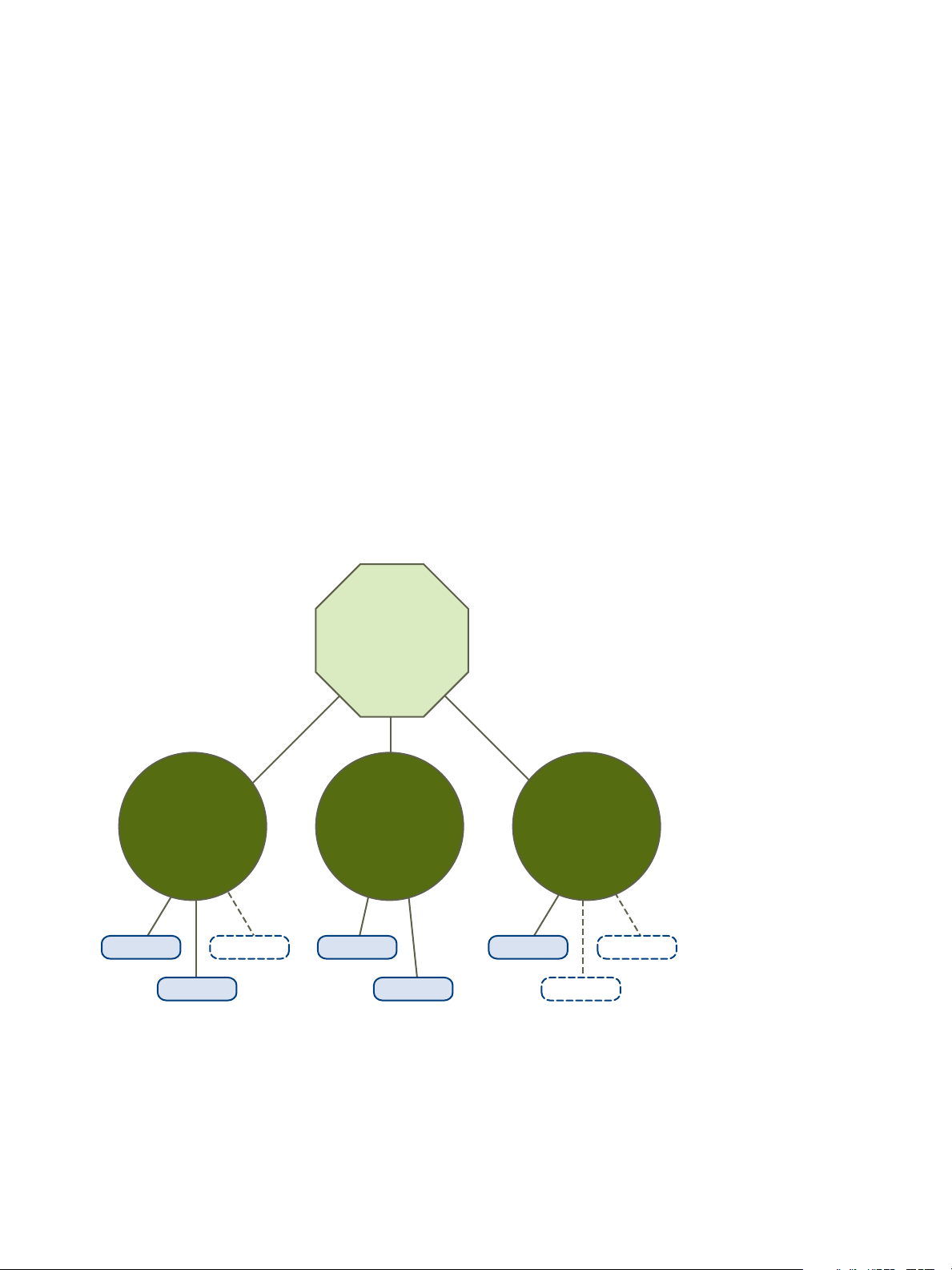
cluster
Total Capacity: 12G
Reserved Capacity: 11G
Available Capacity: 1G
RP1
Reservation: 4G
Reservation Used: 4G
Unreserved: 0G
RP2
Reservation: 4G
Reservation Used: 3G
Unreserved: 1G
RP3
Reservation: 3G
Reservation Used: 3G
Unreserved: 0G
VM1, 2G
VM7, 2G
VM2, 2G
VM4, 1G VM8, 2G
VM3, 3G VM5, 2GVM6, 2G
vSphere Resource Management
When considering cluster validity scenarios, you should understand these terms.
Reservation A fixed, guaranteed allocation for the resource pool input by the user.
Reservation Used The sum of the reservation or reservation used (whichever is larger) for
each child resource pool, added recursively.
Unreserved This nonnegative number differs according to resource pool type.
n
Nonexpandable resource pools: Reservation minus reservation used.
n
Expandable resource pools: (Reservation minus reservation used) plus
any unreserved resources that can be borrowed from its ancestor
resource pools.
Valid DRS Clusters
A valid cluster has enough resources to meet all reservations and to support all running virtual machines.
The following figure shows an example of a valid cluster with fixed resource pools and how its CPU and
memory resources are computed.
Figure 12‑1. Valid Cluster with Fixed Resource Pools
The cluster has the following characteristics:
n
n
n
VMware, Inc. 87
A cluster with total resources of 12GHz.
Three resource pools, each of type Fixed (Expandable Reservation is not selected).
The total reservation of the three resource pools combined is 11GHz (4+4+3 GHz). The total is shown
in the Reserved Capacity field for the cluster.
Page 88
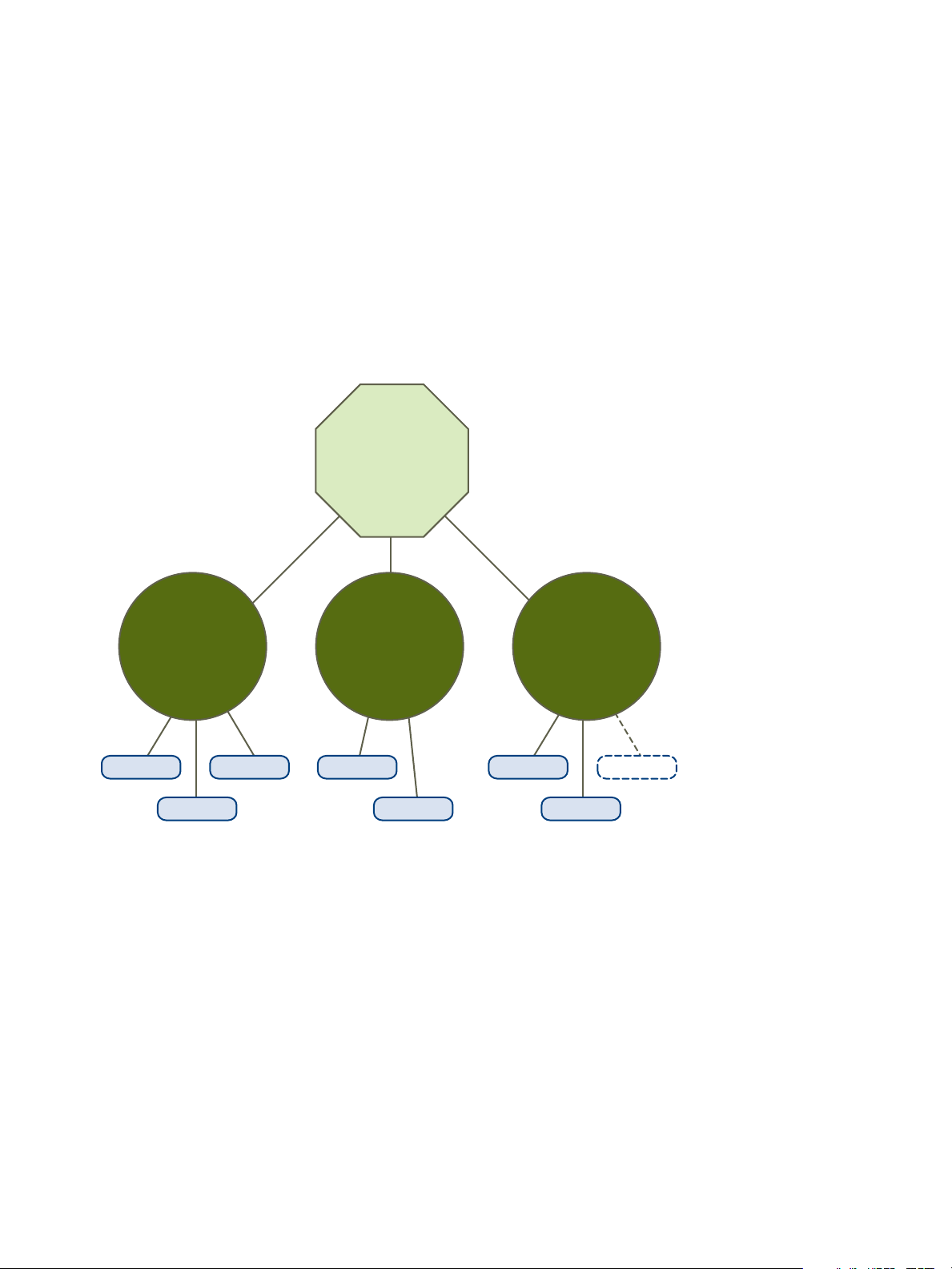
cluster
Total Capacity: 16G
Reserved Capacity: 16G
Available Capacity: 0G
RP1 (expandable)
Reservation: 4G
Reservation Used: 6G
Unreserved: 0G
RP2
Reservation: 5G
Reservation Used: 3G
Unreserved: 2G
RP3 (expandable)
Reservation: 5G
Reservation Used: 5G
Unreserved: 0G
VM1, 2G
VM7, 2G
VM2, 2G
VM4, 1G VM8, 2G
VM3, 3G VM5, 2GVM6, 2G
vSphere Resource Management
n
RP1 was created with a reservation of 4GHz. Two virtual machines. (VM1 and VM7) of 2GHz each
are powered on (Reservation Used: 4GHz). No resources are left for powering on additional virtual
machines. VM6 is shown as not powered on. It consumes none of the reservation.
n
RP2 was created with a reservation of 4GHz. Two virtual machines of 1GHz and 2GHz are powered
on (Reservation Used: 3GHz). 1GHz remains unreserved.
n
RP3 was created with a reservation of 3GHz. One virtual machine with 3GHz is powered on. No
resources for powering on additional virtual machines are available.
The following figure shows an example of a valid cluster with some resource pools (RP1 and RP3) using
reservation type Expandable.
Figure 12‑2. Valid Cluster with Expandable Resource Pools
A valid cluster can be configured as follows:
n
n
n
n
VMware, Inc. 88
A cluster with total resources of 16GHz.
RP1 and RP3 are of type Expandable, RP2 is of type Fixed.
The total reservation used of the three resource pools combined is 16GHz (6GHz for RP1, 5GHz for
RP2, and 5GHz for RP3). 16GHz shows up as the Reserved Capacity for the cluster at top level.
RP1 was created with a reservation of 4GHz. Three virtual machines of 2GHz each are powered on.
Two of those virtual machines (for example, VM1 and VM7) can use RP1’s reservations, the third
virtual machine (VM6) can use reservations from the cluster’s resource pool. (If the type of this
resource pool were Fixed, you could not power on the additional virtual machine.)
Page 89

X
cluster
Total Capacity: 12G 8G
Reserved Capacity: 12G
Available Capacity: 0G
RP1 (expandable)
Reservation: 4G
Reservation Used: 4G
Unreserved: 0G
RP2
Reservation: 5G
Reservation Used: 3G
Unreserved: 2G
RP3 (expandable)
Reservation: 3G
Reservation Used: 3G
Unreserved: 0G
VM1, 2G
VM7, 0G
VM2, 2G
VM4, 1G
VM3, 3G VM5, 5GVM6, 2G
vSphere Resource Management
n
RP2 was created with a reservation of 5GHz. Two virtual machines of 1GHz and 2GHz are powered
on (Reservation Used: 3GHz). 2GHz remains unreserved.
RP3 was created with a reservation of 5GHz. Two virtual machines of 3GHz and 2GHz are powered
on. Even though this resource pool is of type Expandable, no additional 2GHz virtual machine can be
powered on because the parent’s extra resources are already used by RP1.
Overcommitted DRS Clusters
A cluster becomes overcommitted (yellow) when the tree of resource pools and virtual machines is
internally consistent but the cluster does not have the capacity to support all resources reserved by the
child resource pools.
There will always be enough resources to support all running virtual machines because, when a host
becomes unavailable, all its virtual machines become unavailable. A cluster typically turns yellow when
cluster capacity is suddenly reduced, for example, when a host in the cluster becomes unavailable.
VMware recommends that you leave adequate additional cluster resources to avoid your cluster turning
yellow.
Figure 12‑3. Yellow Cluster
In this example:
n
n
n
VMware, Inc. 89
A cluster with total resources of 12GHz coming from three hosts of 4GHz each.
Three resource pools reserving a total of 12GHz.
The total reservation used by the three resource pools combined is 12GHz (4+5+3 GHz). That shows
up as the Reserved Capacity in the cluster.
Page 90

vSphere Resource Management
n
One of the 4GHz hosts becomes unavailable, so total resources reduce to 8GHz.
n
At the same time, VM4 (1GHz) and VM3 (3GHz), which were running on the host that failed, are no
longer running.
n
The cluster is now running virtual machines that require a total of 6GHz. The cluster still has 8GHz
available, which is sufficient to meet virtual machine requirements.
The resource pool reservations of 12GHz can no longer be met, so the cluster is marked as yellow.
Invalid DRS Clusters
A cluster enabled for DRS becomes invalid (red) when the tree is no longer internally consistent, that is,
resource constraints are not observed.
The total amount of resources in the cluster does not affect whether the cluster is red. A cluster can be
red, even if enough resources exist at the root level, if there is an inconsistency at a child level.
You can resolve a red DRS cluster problem either by powering off one or more virtual machines, moving
virtual machines to parts of the tree that have sufficient resources, or editing the resource pool settings in
the red part. Adding resources typically helps only when you are in the yellow state.
A cluster can also turn red if you reconfigure a resource pool while a virtual machine is failing over. A
virtual machine that is failing over is disconnected and does not count toward the reservation used by the
parent resource pool. You might reduce the reservation of the parent resource pool before the failover
completes. After the failover is complete, the virtual machine resources are again charged to the parent
resource pool. If the pool’s usage becomes larger than the new reservation, the cluster turns red.
If a user is able to start a virtual machine (in an unsupported way) with a reservation of 3GHz under
resource pool 2, the cluster would become red, as shown in the following figure.
VMware, Inc. 90
Page 91

cluster
Total Capacity: 12G
Reserved Capacity: 12G 15G
Available Capacity: 0G
RP1 (expandable)
Reservation: 4G
Reservation Used: 4G
Unreserved: 0G
RP2
Reservation: 2G
Reservation Used: 2G 5G
Unreserved: 0G
RP3 (expandable)
Reservation: 6G
Reservation Used: 2G
Unreserved: 4G 0G
VM1, 1G
VM7, 3G
VM2, 3G VM3, 1G VM4, 1G VM5, 1G VM6, 1G
vSphere Resource Management
Figure 12‑4. Red Cluster
Managing Power Resources
The vSphere Distributed Power Management (DPM) feature allows a DRS cluster to reduce its power
consumption by powering hosts on and off based on cluster resource utilization.
vSphere DPM monitors the cumulative demand of all virtual machines in the cluster for memory and CPU
resources and compares this to the total available resource capacity of all hosts in the cluster. If sufficient
excess capacity is found, vSphere DPM places one or more hosts in standby mode and powers them off
after migrating their virtual machines to other hosts. Conversely, when capacity is deemed to be
inadequate, DRS brings hosts out of standby mode (powers them on) and uses vMotion to migrate virtual
machines to them. When making these calculations, vSphere DPM considers not only current demand,
but it also honors any user-specified virtual machine resource reservations.
If you enable Forecasted Metrics when you create a DRS cluster, DPM will issue proposals in advance
depending on the rolling forecast window you select.
Note ESXi hosts cannot automatically be brought out of standby mode unless they are running in a
cluster managed by vCenter Server.
VMware, Inc. 91
Page 92

vSphere Resource Management
vSphere DPM can use one of three power management protocols to bring a host out of standby mode:
Intelligent Platform Management Interface (IPMI), Hewlett-Packard Integrated Lights-Out (iLO), or Wake-
On-LAN (WOL). Each protocol requires its own hardware support and configuration. If a host does not
support any of these protocols it cannot be put into standby mode by vSphere DPM. If a host supports
multiple protocols, they are used in the following order: IPMI, iLO, WOL.
Note Do not disconnect a host in standby mode or move it out of the DRS cluster without first powering
it on, otherwise vCenter Server is not able to power the host back on.
Configure IPMI or iLO Settings for vSphere DPM
IPMI is a hardware-level specification and Hewlett-Packard iLO is an embedded server management
technology. Each of them describes and provides an interface for remotely monitoring and controlling
computers.
You must perform the following procedure on each host.
Prerequisites
Both IPMI and iLO require a hardware Baseboard Management Controller (BMC) to provide a gateway
for accessing hardware control functions, and allow the interface to be accessed from a remote system
using serial or LAN connections. The BMC is powered-on even when the host itself is powered-off. If
properly enabled, the BMC can respond to remote power-on commands.
If you plan to use IPMI or iLO as a wake protocol, you must configure the BMC. BMC configuration steps
vary according to model. See your vendor’s documentation for more information. With IPMI, you must
also ensure that the BMC LAN channel is configured to be always available and to allow operator-
privileged commands. On some IPMI systems, when you enable "IPMI over LAN" you must configure this
in the BIOS and specify a particular IPMI account.
vSphere DPM using only IPMI supports MD5- and plaintext-based authentication, but MD2-based
authentication is not supported. vCenter Server uses MD5 if a host's BMC reports that it is supported and
enabled for the Operator role. Otherwise, plaintext-based authentication is used if the BMC reports it is
supported and enabled. If neither MD5 nor plaintext authentication is enabled, IPMI cannot be used with
the host and vCenter Server attempts to use Wake-on-LAN.
Procedure
1 Browse to the host in the vSphere Client.
2 Click the Configure tab.
3 Under System, click Power Management.
4 Click Edit.
5 Enter the following information.
n
User name and password for a BMC account. (The user name must have the ability to remotely
power the host on.)
VMware, Inc. 92
Page 93

vSphere Resource Management
n
IP address of the NIC associated with the BMC, as distinct from the IP address of the host. The
IP address should be static or a DHCP address with infinite lease.
n
MAC address of the NIC associated with the BMC.
6 Click OK.
Test Wake-on-LAN for vSphere DPM
The use of Wake-on-LAN (WOL) for the vSphere DPM feature is fully supported, if you configure and
successfully test it according to the VMware guidelines. You must perform these steps before enabling
vSphere DPM for a cluster for the first time or on any host that is being added to a cluster that is using
vSphere DPM.
Prerequisites
Before testing WOL, ensure that your cluster meets the prerequisites.
n
Your cluster must contain at least two hosts that are version ESX 3.5 (or ESX 3i version 3.5) or later.
n
Each host's vMotion networking link must be working correctly. The vMotion network should also be a
single IP subnet, not multiple subnets separated by routers.
n
The vMotion NIC on each host must support WOL. To check for WOL support, first determine the
name of the physical network adapter corresponding to the VMkernel port by selecting the host in the
inventory panel of the vSphere Client, selecting the Configuration tab, and clicking Networking.
After you have this information, click on Network Adapters and find the entry corresponding to the
network adapter. The Wake On LAN Supported column for the relevant adapter should show Yes.
n
To display the WOL-compatibility status for each NIC on a host, select the host in the inventory panel
of the vSphere Client, select the Configuration tab, and click Network Adapters. The NIC must
show Yes in the Wake On LAN Supported column.
n
The switch port that each WOL-supporting vMotion NIC is plugged into should be set to auto
negotiate the link speed, and not set to a fixed speed (for example, 1000 Mb/s). Many NICs support
WOL only if they can switch to 100 Mb/s or less when the host is powered off.
After you verify these prerequisites, test each ESXi host that is going to use WOL to support vSphere
DPM. When you test these hosts, ensure that the vSphere DPM feature is disabled for the cluster.
Caution Ensure that any host being added to a vSphere DPM cluster that uses WOL as a wake protocol
is tested and disabled from using power management if it fails the testing. If this is not done, vSphere
DPM might power off hosts that it subsequently cannot power back up.
Procedure
1 Browse to the host in the vSphere Client.
2 Right-click the host and select Power > Enter Standby Mode
This action powers down the host.
3 Right-click the host and select Power > Power On to attempt to bring it out of standby mode.
VMware, Inc. 93
Page 94

vSphere Resource Management
4 Observe whether or not the host successfully powers back on.
5 For any host that fails to exit standby mode successfully, perform the following steps.
a Select the host in the vSphere Client and select the Configure tab.
b Under Hardware > Power Management, click Edit to adjust the power management policy.
After you do this, vSphere DPM does not consider that host a candidate for being powered off.
Enabling vSphere DPM for a DRS Cluster
After you have performed configuration or testing steps required by the wake protocol you are using on
each host, you can enable vSphere DPM.
Configure the power management automation level, threshold, and host-level overrides. These settings
are configured under Power Management in the cluster’s Settings dialog box.
You can also create scheduled tasks to enable and disable DPM for a cluster using the Schedule Task:
Change Cluster Power Settings wizard.
Note If a host in your DRS cluster has USB devices connected, disable DPM for that host. Otherwise,
DPM might turn off the host and sever the connection between the device and the virtual machine that
was using it.
Automation Level
Whether the host power state and migration recommendations generated by vSphere DPM are run
automatically or not depends upon the power management automation level selected for the feature.
The automation level is configured under Power Management in the cluster’s Settings dialog box.
Note The power management automation level is not the same as the DRS automation level.
Table 12‑1. Power Management Automation Level
Option Description
Off The feature is disabled and no recommendations are made.
Manual Host power operation and related virtual machine migration recommendations are made, but not
automatically run.
Automatic Host power operations are automatically run if related virtual machine migrations can all be run
automatically.
vSphere DPM Threshold
The power state (host power on or off) recommendations generated by the vSphere DPM feature are
assigned priorities that range from priority-one recommendations to priority-five recommendations.
These priority ratings are based on the amount of over- or under-utilization found in the DRS cluster and
the improvement that is expected from the intended host power state change. A priority-one
recommendation is mandatory, while a priority-five recommendation brings only slight improvement.
VMware, Inc. 94
Page 95

vSphere Resource Management
The threshold is configured under Power Management in the cluster’s Settings dialog box. Each level
you move the vSphere DPM Threshold slider to the right allows the inclusion of one more lower level of
priority in the set of recommendations that are executed automatically or appear as recommendations to
be manually executed. At the Conservative setting, vSphere DPM only generates priority-one
recommendations, the next level to the right only priority-two and higher, and so on, down to the
Aggressive level which generates priority-five recommendations and higher (that is, all
recommendations.)
Note The DRS threshold and the vSphere DPM threshold are essentially independent. You can
differentiate the aggressiveness of the migration and host-power-state recommendations they
respectively provide.
Host-Level Overrides
When you enable vSphere DPM in a DRS cluster, by default all hosts in the cluster inherit its vSphere
DPM automation level.
You can override this default for an individual host by selecting the Host Options page of the cluster's
Settings dialog box and clicking its Power Management setting. You can change this setting to the
following options:
n
Disabled
n
Manual
n
Automatic
Note Do not change a host's Power Management setting if it has been set to Disabled due to failed exit
standby mode testing.
After enabling and running vSphere DPM, you can verify that it is functioning properly by viewing each
host’s Last Time Exited Standby information displayed on the Host Options page in the cluster Settings
dialog box and on the Hosts tab for each cluster. This field shows a timestamp and whether vCenter
Server Succeeded or Failed the last time it attempted to bring the host out of standby mode. If no such
attempt has been made, the field displays Never.
Note Times for the Last Time Exited Standby text box are derived from the vCenter Server event log. If
this log is cleared, the times are reset to Never.
Monitoring vSphere DPM
You can use event-based alarms in vCenter Server to monitor vSphere DPM.
VMware, Inc. 95
Page 96

vSphere Resource Management
The most serious potential error you face when using vSphere DPM is the failure of a host to exit standby
mode when its capacity is needed by the DRS cluster. You can monitor for instances when this error
occurs by using the preconfigured Exit Standby Error alarm in vCenter Server. If vSphere DPM cannot
bring a host out of standby mode (vCenter Server event DrsExitStandbyModeFailedEvent), you can
configure this alarm to send an alert email to the administrator or to send notification using an SNMP trap.
By default, this alarm is cleared after vCenter Server is able to successfully connect to that host.
To monitor vSphere DPM activity, you can also create alarms for the following vCenter Server events.
Table 12‑2. vCenter Server Events
Event Type Event Name
Entering Standby mode (about to power off host)
Successfully entered Standby mode (host power off succeeded)
Exiting Standby mode (about to power on the host)
Successfully exited Standby mode (power on succeeded)
DrsEnteringStandbyModeEvent
DrsEnteredStandbyModeEvent
DrsExitingStandbyModeEvent
DrsExitedStandbyModeEvent
For more information about creating and editing alarms, see the vSphere Monitoring and Performance
documentation.
If you use monitoring software other than vCenter Server, and that software triggers alarms when physical
hosts are powered off unexpectedly, you might have a situation where false alarms are generated when
vSphere DPM places a host into standby mode. If you do not want to receive such alarms, work with your
vendor to deploy a version of the monitoring software that is integrated with vCenter Server. You could
also use vCenter Server itself as your monitoring solution, because starting with vSphere 4.x, it is
inherently aware of vSphere DPM and does not trigger these false alarms.
Using DRS Anity Rules
You can control the placement of virtual machines on hosts within a cluster by using affinity rules.
You can create two types of rules.
n
Used to specify affinity or anti-affinity between a group of virtual machines and a group of hosts. An
affinity rule specifies that the members of a selected virtual machine DRS group can or must run on
the members of a specific host DRS group. An anti-affinity rule specifies that the members of a
selected virtual machine DRS group cannot run on the members of a specific host DRS group.
See VM-Host Affinity Rules for information about creating and using this type of rule.
n
Used to specify affinity or anti-affinity between individual virtual machines. A rule specifying affinity
causes DRS to try to keep the specified virtual machines together on the same host, for example, for
performance reasons. With an anti-affinity rule, DRS tries to keep the specified virtual machines
apart, for example, so that when a problem occurs with one host, you do not lose both virtual
machines.
See VM-VM Affinity Rules for information about creating and using this type of rule.
VMware, Inc. 96
Page 97

vSphere Resource Management
When you add or edit an affinity rule, and the cluster's current state is in violation of the rule, the system
continues to operate and tries to correct the violation. For manual and partially automated DRS clusters,
migration recommendations based on rule fulfillment and load balancing are presented for approval. You
are not required to fulfill the rules, but the corresponding recommendations remain until the rules are
fulfilled.
To check whether any enabled affinity rules are being violated and cannot be corrected by DRS, select
the cluster's DRS tab and click Faults. Any rule currently being violated has a corresponding fault on this
page. Read the fault to determine why DRS is not able to satisfy the particular rule. Rules violations also
produce a log event.
Note VM-VM and VM-Host affinity rules are different from an individual host’s CPU affinity rules.
Create a Host DRS Group
A VM-Host affinity rule establishes an affinity (or anti-affinity) relationship between a virtual machine DRS
group with a host DRS group. You must create both of these groups before you can create a rule that
links them.
Procedure
1 Browse to the cluster in the vSphere Client.
2 Click the Configure tab.
3 Under Configuration, select VM/Host Groups and click Add.
4 In the Create VM/Host Group dialog box, type a name for the group.
5 Select Host Group from the Type drop down box and click Add.
6 Click the check box next to a host to add it. Continue this process until all desired hosts have been
added.
7 Click OK.
What to do next
Using this host DRS group, you can create a VM-Host affinity rule that establishes an affinity (or anti-
affinity) relationship with an appropriate virtual machine DRS group.
Create a Virtual Machine DRS Group
Create a VM-Host Affinity Rule
Create a Virtual Machine DRS Group
Affinity rules establish an affinity (or anti-affinity) relationship between DRS groups. You must create DRS
groups before you can create a rule that links them.
Procedure
1 Browse to the cluster in the vSphere Client.
VMware, Inc. 97
Page 98

vSphere Resource Management
2 Click the Configure tab.
3 Under Configuration, select VM/Host Groups and click Add.
4 In the Create VM/Host Group dialog box, type a name for the group.
5 Select VM Group from the Type drop down box and click Add.
6 Click the check box next to a virtual machine to add it. Continue this process until all desired virtual
machines have been added.
7 Click OK.
What to do next
Create a Host DRS Group
Create a VM-Host Affinity Rule
Create a VM-VM Affinity Rule
VM-VM Anity Rules
A VM-VM affinity rule specifies whether selected individual virtual machines should run on the same host
or be kept on separate hosts. This type of rule is used to create affinity or anti-affinity between individual
virtual machines that you select.
When an affinity rule is created, DRS tries to keep the specified virtual machines together on the same
host. You might want to do this, for example, for performance reasons.
With an anti-affinity rule, DRS tries to keep the specified virtual machines apart. You could use such a rule
if you want to guarantee that certain virtual machines are always on different physical hosts. In that case,
if a problem occurs with one host, not all virtual machines would be placed at risk.
Create a VM-VM Anity Rule
You can create VM-VM affinity rules to specify whether selected individual virtual machines should run on
the same host or be kept on separate hosts.
Note If you use the vSphere HA Specify Failover Hosts admission control policy and designate multiple
failover hosts, VM-VM affinity rules are not supported.
Procedure
1 Browse to the cluster in the vSphere Client.
2 Click the Configure tab.
3 Under Configuration, click VM/Host Rules.
4 Click Add.
5 In the Create VM/Host Rule dialog box, type a name for the rule.
VMware, Inc. 98
Page 99

vSphere Resource Management
6 From the Type drop-down menu, select either Keep Virtual Machines Together or Separate Virtual
Machines.
7 Click Add.
8 Select at least two virtual machines to which the rule will apply and click OK.
9 Click OK.
VM-VM Anity Rule Conflicts
You can create and use multiple VM-VM affinity rules, however, this might lead to situations where the
rules conflict with one another.
If two VM-VM affinity rules are in conflict, you cannot enable both. For example, if one rule keeps two
virtual machines together and another rule keeps the same two virtual machines apart, you cannot enable
both rules. Select one of the rules to apply and disable or remove the conflicting rule.
When two VM-VM affinity rules conflict, the older one takes precedence and the newer rule is disabled.
DRS only tries to satisfy enabled rules and disabled rules are ignored. DRS gives higher precedence to
preventing violations of anti-affinity rules than violations of affinity rules.
VM-Host Anity Rules
A VM-Host affinity rule specifies whether or not the members of a selected virtual machine DRS group
can run on the members of a specific host DRS group.
Unlike a VM-VM affinity rule, which specifies affinity (or anti-affinity) between individual virtual machines, a
VM-Host affinity rule specifies an affinity relationship between a group of virtual machines and a group of
hosts. There are 'required' rules (designated by "must") and 'preferential' rules (designated by "should".)
A VM-Host affinity rule includes the following components.
n
One virtual machine DRS group.
n
One host DRS group.
n
A designation of whether the rule is a requirement ("must") or a preference ("should") and whether it
is affinity ("run on") or anti-affinity ("not run on").
Because VM-Host affinity rules are cluster-based, the virtual machines and hosts that are included in a
rule must all reside in the same cluster. If a virtual machine is removed from the cluster, it loses its DRS
group affiliation, even if it is later returned to the cluster.
Create a VM-Host Anity Rule
You can create VM-Host affinity rules to specify whether or not the members of a selected virtual machine
DRS group can run on the members of a specific host DRS group.
Prerequisites
Create the virtual machine and host DRS groups to which the VM-Host affinity rule applies.
VMware, Inc. 99
Page 100

vSphere Resource Management
Procedure
1 Browse to the cluster in the vSphere Client.
2 Click the Configure tab.
3 Under Configuration, click VM/Host Rules.
4 Click Add.
5 In the Create VM/Host Rule dialog box, type a name for the rule.
6 From the Type drop down menu, select Virtual Machines to Hosts.
7 Select the virtual machine DRS group and the host DRS group to which the rule applies.
8 Select a specification for the rule.
n
Must run on hosts in group. Virtual machines in VM Group 1 must run on hosts in Host Group
A.
n
Should run on hosts in group. Virtual machines in VM Group 1 should, but are not required, to
run on hosts in Host Group A.
n
Must not run on hosts in group. Virtual machines in VM Group 1 must never run on host in
Host Group A.
n
Should not run on hosts in group. Virtual machines in VM Group 1 should not, but might, run
on hosts in Host Group A.
9 Click OK.
Using VM-Host Anity Rules
You use a VM-Host affinity rule to specify an affinity relationship between a group of virtual machines and
a group of hosts. When using VM-Host affinity rules, you should be aware of when they could be most
useful, how conflicts between rules are resolved, and the importance of caution when setting required
affinity rules.
One use case where VM-Host affinity rules are helpful is when the software you are running in your virtual
machines has licensing restrictions. You can place such virtual machines into a DRS group and then
create a rule that requires them to run on a host DRS group that contains only host machines that have
the required licenses.
Note When you create a VM-Host affinity rule that is based on the licensing or hardware requirements of
the software running in your virtual machines, you are responsible for ensuring that the groups are
properly set up. The rule does not monitor the software running in the virtual machines nor does it know
what non-VMware licenses are in place on which ESXi hosts.
If you create more than one VM-Host affinity rule, the rules are not ranked, but are applied equally. Be
aware that this has implications for how the rules interact. For example, a virtual machine that belongs to
two DRS groups, each of which belongs to a different required rule, can run only on hosts that belong to
both of the host DRS groups represented in the rules.
VMware, Inc. 100
 Loading...