

Vitek VT-3485 SERVICE MANUAL
VT-3485
CAUTION: Before servicing the chassis, read the "Important Service Safety Information"
section on page 2 of this manual.
RADIO CASSETTE RECORDER WITH CD/MP3 PLAYER
STNETNOC
IMPORTANT SERVICE SAFETY INFORMATION
SPECIFICATIONS
DISASSEMBLY INSTRUCTIONS
ALIGNMENT PROCEDURES
TROUBLESHOOTING GUIDE
BLOCK DIAGRAM
WIRING DIAGRAM
IC BLOCK DIAGRAM
PRINTED CIRCUIT BOARDS
SCHEMATIC DIAGRAMS
EXPLODED VIEW
EXPLODED PARTS LIST
REPLACEMENT PARTS LIST
2
3-6
7
8
9
10
11
12-15
16-22
23-26
27
28
29-40
IMPORTANT SERVICE SAFETY INFORMATION
1.
SAFETY PRECAUTIONS
Before returning a unit to the customer, always make a safety check of
the entire unit, including, but not limited to the following items:
a. Be sure that no built-in protective devices are defective and/or have
been defeated during servicing.
(1)
Protective shields are provided to protect both the technician and
the customer. Correctly replace all missing protective shields
including any removed for servicing convenience.
(2)
When reinstalling the chassis and/or other assemblies in the
cabinet, be sure t put back in place all protective devices, including,
but not limited to, nonmetallic control knobs, insulating fishpapers,
adjustment and compartment covers/shields and isolation resistor/
capacitor networks. Do not operate this unit or permit it to be
operated without all protective devices correctly installed and
functioning.
b.
Be sure that there are no cabinet openings through which an adult or
child might be able to insert their fingers and contact a hazardous
voltage. such openings include, but are not limited to, excessively wide
cabinet ventilation slots, and an improperly fitted and/or incorrectly
secured cabinet back cover.
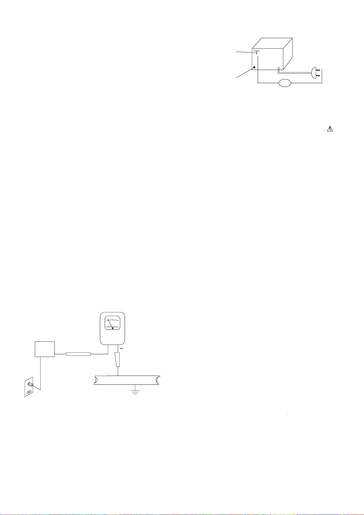
c.
" Leakage Current Hot Check - With the unit completely reassembled,
plug the AC line cord directly into a (EU voltage)V AC outlet. (Do not
use an isolation transformer during this test.) Use a leakage current
tester or a metering system that complies with IEC60990 figure 4. With
the unit AC switch first in the ON position and then in the OFF position,
measure from a known earth ground (metal water pipe, conduit, etc.),
especially any exposed metal parts that offer an electrical return path to
the chassis. Any current measured must not exceed the following
values:
. for a.c.: U1 = 35 V (peak) and U2 = 0,35 V (peak);
. for d.c.: U1 = 1,0 V.
NOTE: The limit values of U2 = 0,35 V (peak) for a.c. and U1 = 1,0 V for
d.c. correspond to the values 0,7 mA(peak) a.c. and 2,0 mA d.c.
The limit value U1 = 35 V (peak) for a.c. corresponds to the value 70
mA (peak) a.c. for frequencies greater than 100 kHz.
Reverse the unit power cord plug in the outlet and repeat test. ANY
MEASUREMENTS NOT WITHIN THE LIMITS SPECIFIED HERENIN
INDICATE A POTENTIAL SHOCK HAZARD THAT MUST BE
ELIMINATED BEFORE RETURNING THE UNIT TO THE CUSTOMER.
"
(READING SHOULD
NOT BE ABOVE
0.5mA)
AC Leakage Test
DEVICE
UNDER
TEST
2-WIRE CORD
ALSO TEST WITH
PLUG REVERSED
(USING AC ADAPTER
PLUG AS REQUIRED)
d.
Insulation Resistance Test Cold Check
Unplug the power supply cord and connect a jumper wire between the
two prongs of the plug.
Turn on the power switch of the unit.
Measure the resistance with an ohmmeter between the jumpered AC
plug and each exposed metallic cabinet part on the unit, such as
screwheads, antenna, control shafts, handle brackets, etc. When the
exposed metallic part has a return path to the chassis, the reading
should be between 1 and 5.2 megohms. When there is no return path to
the chassis, the reading must be “infinite”. If it is not within the limits
specified, there is the possibility of a shock hazard, and the unit must be
repaired and rechecked before it is returned to the customer.
TEST ALL
EXPOSED METAL
SURFACES
+
LEAKAGE
CURRENT
TESTER
EARTH
GROUND
ANTENNA
TERMINAL
EXPOSED
METAL
PART
2.
PRODUCT SAFETY NOTICE
OM
OHMMETER
Some electrical and mechanical parts have special safety related
characteristics which are often not evident from visual inspection, nor
can the protection they give necessarily be obtained by replacing them
with components rated for higher voltage, wattage, etc. Parts that
have special safety characteristics are identified by a on
schematic and parts list. Use of a substitute replacement that does not
have the same safety characteristics as the recommended
replacement part might create shock, fire, and/or other hazards.
Product safety is under review continuously and new instructio ns are
issued whenever appropriate.
SERVICING PRECAUTIONS
3.
CAUTION”Before servicing the unit covered by this service manual
and its supplements read and follow the SAFETY PRECAUTIONS on
this page. NOTE”If unforeseen circumstances create a conflit
between the following servicing precautions and any of the safety
precautions, always follow the safety precautions. Rem ember: Safety
First.
General Servicing Precautions.
a. Always unplug the unit’s AC power cord from the AC power
source before:
(1) removing or reinstalling any component, circuit board, module, or
any other unit assembly.
(2) disconnecting or reconnecting any unit electrical plug or other
electrical connection.
(3) connecting a test substitute in parallel with an electrolytic
capacitor in the unit.
Caution: A wrong part substitution or incorrect polarity installation
of electrolytic capacitors may result in an explosion
hazard.
b. Do not defeat any plug/socket B+ voltage interlocks with which
the unit covered by this service manual might be equipped.
c. Do not apply AC power to this unit and/or any of its electrical
assemblies unless all solid-state device heat sinks are correctly
installed.
d. always connect a test unit instrument’s ground lead to the unit’s
chassis ground before connecting the test instrument’s positive
lead. Always remove the test instrument’s ground lead last.
LASER PRECAUTIONS
4.
WARNING!!
When servicing, (in case it is necessary to confirm Laser Beam
1.
Emission) be sure not to place your eyes any closer than 1 ft or
30cm from the surface of the Objective Lens on the Opticval
Pickup Block.
HANDLING THE LASER PICKUP
2.
Laser diodes are extremely susceptible to damage from static
electricity. Even if a static discharge does not ruin the diode, it can
shorten its life or cause it to work improperly. When replacing the
pickup, use a conductive mat on the floor and desk and wear a
wrist band connected to ground through a 1M ohm resistor to
protect the laser diode from static damage. If the lens should get
dusty, blow off the dust carefully from the object.
3.
There are no adjustable parts in the pickup assembly. If it is
defective, replace the whole pickup assembly.
CAUTION:
USE OF CONTROLS, ADJUSTMENTS OR PERFORMANCE OF
PROCEDURES HEREIN MAY RESULT IN HAZARDOUS
RADIATION EXPOSURE.
DANGER:
IF INTERLOCK FAILS OR IS DEFEATED, THE LASER LIGHT IS
ABLE TO FUNCTION. THE LASER IS INVISIBLE, AVOID DIRECT
EXPOSURE TO BEAM.
2
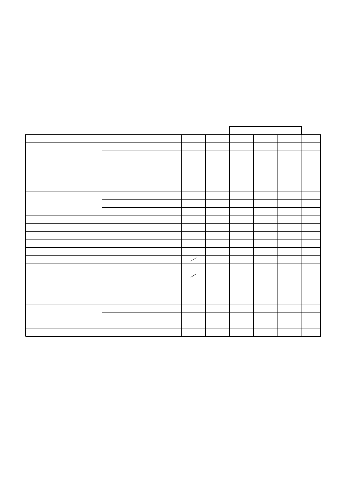
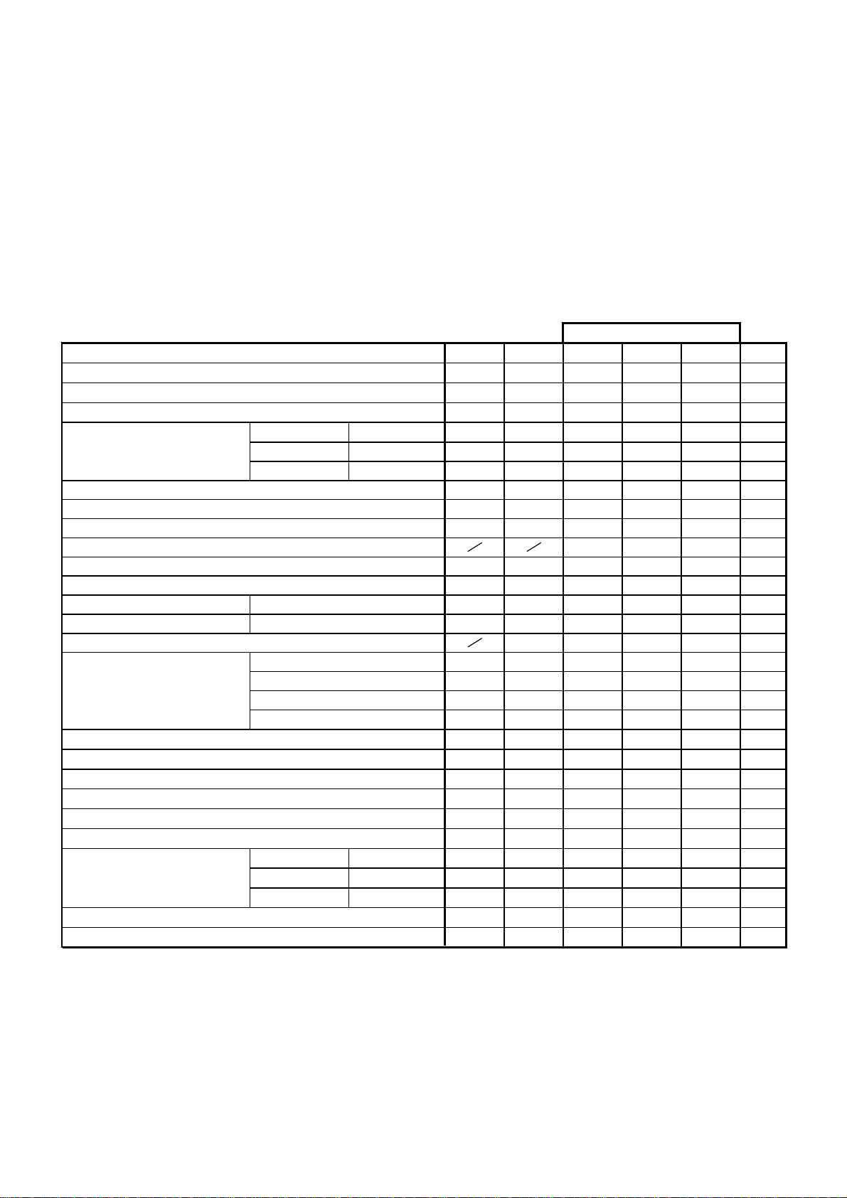
SPECIFICATIONS
GENERAL
POWER INPUT----------------------------------POWER CONSUMPTION---------------------
AM/FM TUNER SECTION
ANTENNA SYSTEM-----------------------------
TUNING RANGE----------------------------------
BAND SECTION:AM
AC 230V, 50Hz
AM: FERRITE BAR
FM: PIG TAIL
AM: 522~1620KHz
FM: 87.5~108MHz
LOW END
HIGH END
AUDIO SECTION
SPEAKER IMPEDANCE-----------------------
SAMPLE
6 ohms
smho23----------------ECNADEPMISENOHPDAEHsttaW02CA
TINU321timiLlamroNMETI
zHK4-/+025EGNAR.10
zHK0255-/+0171
zHK01713+054.F.I.20
M/Bd0548505zHK016
M/Bd948505zHK0001ytivtisneSXAM.30
M/Bd848505zHK0041)Bd6-(
M/Bd048626zHK016rofytivtisneS.40
M/Bd858626zHK0001N/SBd02M/Bd268626zHK0041
M/Bd066606zHK016ytivtisneSnacSOTUA.50
M/Bd454685zHK0001
M/Bd454685zHK0041
Bd450405zHK016tanoitcejeRF.I.60
Bd040252zHK0041tanoitcejeRegaml.70
%101<.F.Ix2zHK009m/Vm5tateewT.80
Bd0251-/+02-/+zHK0001tazHK01-/+.A.C.A.90
zHK2151-5m/Bd001zHK0001taBd6-htdiWdnaB.01
Bd470454m/Bd001zHK0001ta)Bd01-(C.G.A.11
%131tuptuO.FERtanoitrotsiD.21
W28.12m/Bd001%08.DOM@rewoPtuptuOXAM.31
zH05051001woLesnopseRycneuqerF.41
zHK5.32.23hgiHBd6-
Vm131muHemuloVNIM.51
Bd835203m/Bd001zHK0001@muHnoitaludoM.61
3
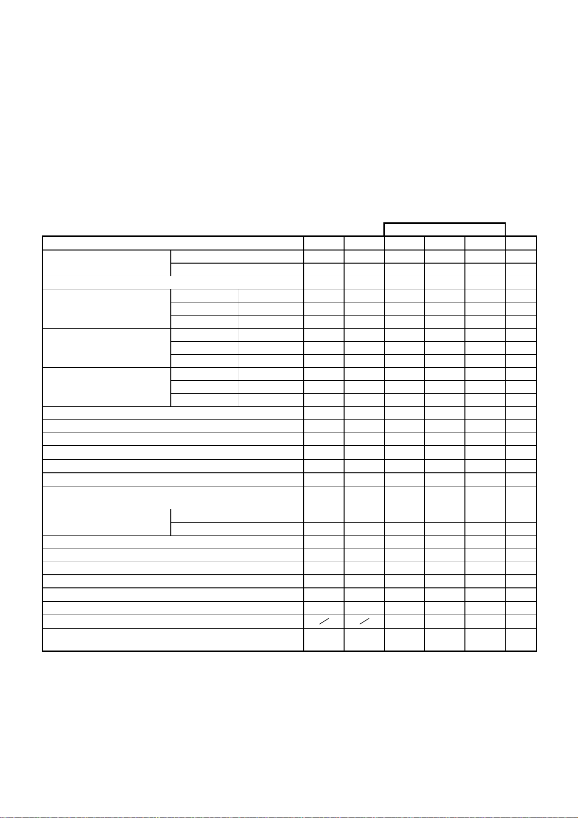
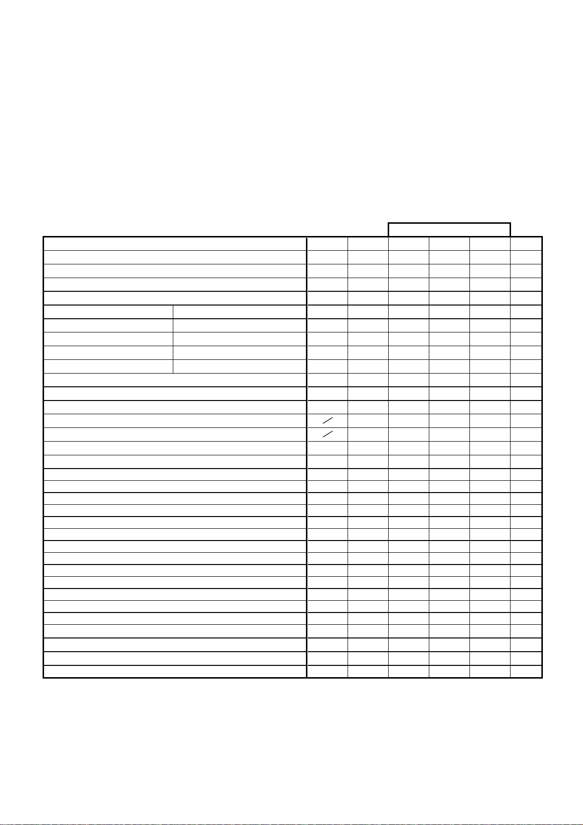
SPECIFICATIONS
GENERAL
POWER INPUT----------------------------------POWER CONSUMPTION---------------------
AC 230V, 50Hz
AUDIO SECTION
SPEAKER IMPEDANCE-----------------------
6 ohms
smho 23----------------ECNADEPMI SENOHPDAEHsttaW02CA
AM/FM TUNER SECTION
ANTENNA SYSTEM-----------------------------
TUNING RANGE----------------------------------
BAND SECTION:AM
AM: FERRITE BAR
FM: PIG TAIL
AM: 522~1620KHz
FM: 87.5~108MHz
SAMPLE
LOW END
HIGH END
12. Power at 75KHz DEV. 1mV
MAX Output Power
14. Modulation Hum @100dB Bd050454
15. MIN Volume Hum Vm131
MULTIPLEX
02. Separation at 98.1MHz with 19KHz Filter at 45K DEV.1mV Bd725282
04. S/N Ratio dB
05. Stereo Distortion at 98.1MHz
REF Output with 19KHz Filter at45KHz 1mV
TINU321timiLlamroNMETI
zHM5.781.0-/+5.78EGNAR.10
zHM8011.0-/+801
zHM7.011.0-/+7.01ycneuqerFetaidemretnl.20
Bd010261zHM1.09
Bd90261zHM1.89ytivtisneSXAM.30
Bd010261zHM1.601)Bd6-(
Bd316222zHM1.09rofytivtisneS.40
Bd316222zHM1.89N/SBd03Bd416222zHM1.601
Bd123372zHM1.09ytivitisneSnacSOTUA.50
Bd123372zHM1.89
Bd323372zHM1.601
Bd055405zHM09tanoitcejeR.F.I.60
Bd928142zHM601tanoitcejeRegamI.70
Bd70342Vm1zHM89taytivtisneSgnitimiLBd3-.80
Bd235203Vm1zHM89tanoisserppuS.M.A.90
Bd450464Vm1zHM89taoitaRN/S.01
%2.031tuptuOFERtanoitrotsiD.11
W28.12
ZH05051001woLesnopseRycneuqerF.31
zHK545hgiHBd6-
Bd415202zHM89taytivtisneSnoitacidnloeretS.10
Bd131ecnalaBlennahC.30
%5.253
4
SPECIFICATIONS
GENERAL
POWER INPUT----------------------------------POWER CONSUMPTION---------------------
AM/FM TUNER SECTION
ANTENNA SYSTEM-----------------------------
TUNING RANGE----------------------------------
BAND SECTION:TAPE
FM 40KHz DEV. 1MV REF Bd0FER
13. Audio Balance
14. Bass Boost at 100Hz
RECORDING / PLAYBACK ( DC BIAS )
AM 50% Modulation 0 Bd13-/+
TAPE -4dB
CD -10dB
AC 230V, 50Hz
AM: FERRITE BAR
FM: PIG TAIL
AM: 522~1620KHz
FM: 87.5~108MHz
AUDIO SECTION
SPEAKER IMPEDANCE-----------------------
SAMPLE
+3 Bd23-/+
-3 Bd3-3-/+
+6 Bd82-/+
6 ohms
smho 23----------------ECNADEPMI SENOHPDAEHsttaW02CA
TINU321timiLlamroNMETI
%1.053.0N111-TTMrettulF&woW.10
%5.131N811-TTMnoitrotsiDkcaByalP.20
zH0603%2-/3+0003N111-TTMdeepSepaT.30
Bd03-/+0zH521
Bd0FERFERzHK1esnopseRycneuqerFyalP.40
Bd06-/3+0zHK01
Bd535203121-TTM)retliFtuohtiW(klaTssorC.50
Bd440353B211-TTM)retliFtuohtiW(oitaRN/S.60
Bd538233141-TTMnoitarapS.70
%talF@QE/PBd0tceffElortnoC.loVXAM.80
W3.222NB211-TTMrewoPtuptuOXAM.90
Bd5.030N811-TTMecnereffiDlennahCR/L.01
Vm131emuloVNIMesioN&muH.11
Vm520453emuloVXAM
CES071<EPYT06-C).WER&.DWF(emiTgnidniW.21
%2016noitrotsiDR/P.10
Bd823282oitaResarEP/R.20
Bd733282oitaRN/SP/R.30
Bd5.030ecnalaBlennahCP/R.40
Bd1-6-/3+0zH521
Bd00FERzHK1esnopseRycneuqerFP/R.50
Bd8-6-/3+0zHK8
Bd33±3+Vm1zHK5.22MFlevelP/R.60
zHK065±zHK06ycneuqerFtnerrucsaiBCA.70
5
SPECIFICATIONS
GENERAL
POWER INPUT----------------------------------POWER CONSUMPTION---------------------
AC 230V, 50Hz
AM/FM TUNER SECTION
ANTENNA SYSTEM-----------------------------
TUNING RANGE----------------------------------
BAND SECTION:TAPE
05. Frequency Response: (TCD-781)
AM: FERRITE BAR
FM: PIG TAIL
AM: 522~1620KHz
FM: 87.5~108MHz
AUDIO SECTION
SPEAKER IMPEDANCE-----------------------
SAMPLE
1-2-/+1-zHK61
6.222rewoPtuptuOemuloVXAM.70
5
575657)A444-CBS(tnirpregniF.21
04107041)117-DCT(yticirtneccE.31
6 ohms
smho 23----------------ECNADEPMI SENOHPDAEHsttaW02CA
TINU321timiLlamroNMETIDC
Bd5.021ecnalaBlennahC.10
%1.021)187-DCT()Bd01-zHK1(noitrotsiD.20
Bd750525)287-DCT()Bd0zHK1(FPBo/wN/S.30
Bd440353)287-DCT()Bd0zHK1(noitarapSlennahC.40
Bd02-/+1-zH721
Bd0FERFERzHK1
dB
Bd1-2-/+2-zHK81
Vm131muHemuloVNIM.60
W
W3.28.12rewoPtuptuOnoitrotsiD%01DC.80
CES36<)287-DCT()KCARTTSRIF(emiTsseccA.90
CES21<)287-DCT()KCARTTSAL(
MU009006009)A444-CBS(noitpurretnl.01
MU008006008)A444-CBS(toDkcalB.11
UM
UM
MU00010080001)R237-DCT(noitaiveDlacitreV.41
6
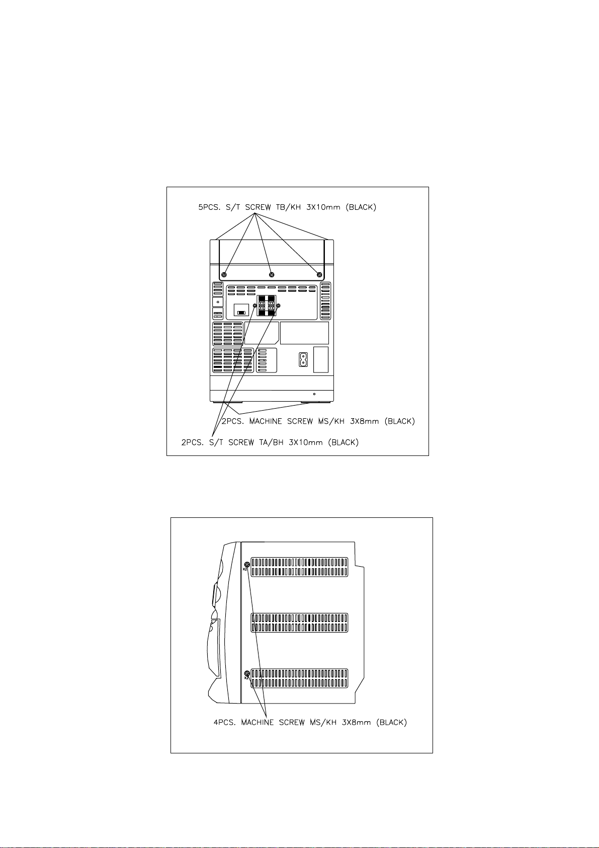
DISASSEMBLY INSTRUCTIONS
1) ROTATE THE UNIT TO EXPOSE THE BACK SIDE.
2) REMOVE THE 9 SCREWS AS SHOWN IN FIG.1.
3) ROTATE THE UNIT TO EXPOSE THE LEFT SIDE AND RIGHT SIDE.
4) REMOVE THE 4 SCREWS AS SHOWN IN FIG.2.
FIG1
FIG2
7
ALIGNMENT PROCEDURES
AM I.F. ALIGNMENT
1. Set the POWER BUTTON to POWER "ON".
2. Set the FUNCTION SELECTOR SWITCH to RAD IO & AM BAND.
3. Connect a SWEEPSCOPE OUTPUT to AM antenna terminal.
4. Connect a SWEEPSCOPE INPUT to pin13 or 14 of IC1 through a 1uf capacitor and ground.
1450KHz GANGOPEN CF2(AMIF)
AM R.F. ALIGNMENT
1. Connect an RF generator to a standard radiating loop.
2. Connect a SCOPE and VTVM across the speaker output.
1 520KHz GANG CLOSED T2 (AMOSCCOIL)
2 1710KHz GANG OPEN CT1 (AM OSC TRIM.) MAX IM UM
3 610KHz 600KHz AMCOIL(AM ANT COIL) OUTPUT
4 1400KHz 1400KHz CT3 (AMANTTRIM.)
5 REPEAT STEPS 3 AND 4 TO OBTAIN BEST TRACKING.
FM I.F. ALIGNMENT
1. Set the POWER SWITCH to POWER "ON" .
2. Set the FUNCTION SELECTOR to RADIO & FM BAND .
3. Connect a SWEEPSCOPE OUTPUT to pin21 of I C1 through a 20pF capacitor and ground.
4. Connect a SWEEPSCOPE INPUT to pin13 or 14 of IC1 through a 1uf capacitor and ground.
1
10.7MHz GAND OPEN CF3 (FM ORG)
& MAXIMUM OUTPUT
MAX.AMPLITUDE
BALANCED CURVE
ROF TSUJDATSUJDALAID TESLANGIS TESPETS
CENTER
ROF TSUJDATSUJDALAID TESLANGIS TESPETS
ROF TSUJDATSUJDALAID TESLANGIS TESPETS
FM R.F. ALIGNMENT
1. Connect an RF generator to the FM antenna terminal and ground.
2. Connect a SCOPE & VTVM across the speaker output.
1
2 108MHz GANG OPEN MAXIMUM
3 90.1MHz 90.1MHz L4 (FM RF COIL) OUTPUT
4 106.1MHz 106.1MHz CT2(FMRF TRIM)
5 REPEAT STEPS 3 AND 4 TO OBTAIN MAX ADJUST.
87.5MHz
GANG CLOSED
L3 (FM OSC COIL)
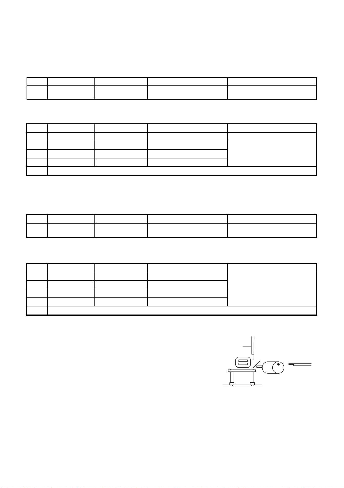
CASSETTE ALIGNMENT
1. Set the FUNCTION SELECTOR SWITCH TO TAPE.
2. Connect a Scope & VTVM across the speaker output.
3. Insert the 8KHz tape in to cassette deck and push play BUTTON.
4. ADJUST HEAD for speaker maximum output.
5. Motor speed adjustment for tape speed.
SCREWDRIVER
ADJUSTING
SCREW
CD ALIGNMENT
Auto alignment.
MOTOR
ROF TSUJDATSUJDALAID TESLANGIS TESPETS
SCREWDRIVER
8

TROUBLESHOOTING GUIDE
9
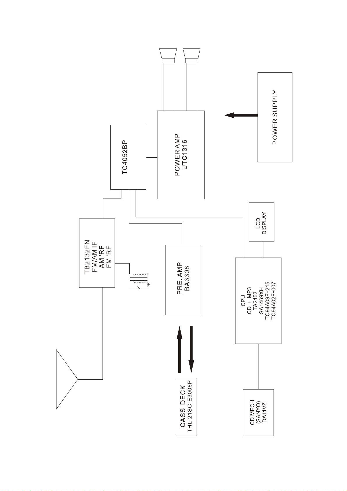
BLOCK DIAGRAM
10
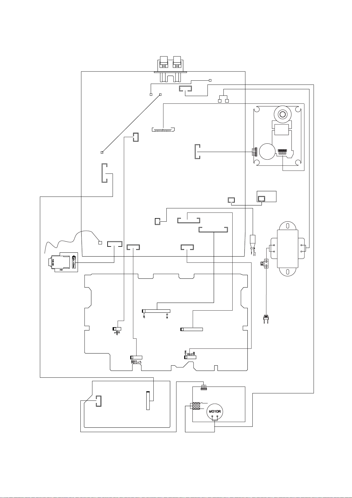
WIRING DIAGRAM
TO SPEAKER
SPKJ1
CN7
CN302
16P 1mm 180C
4P 2.5mm 180C
CN4
3P 2mm 180C
G3
G1
G2
AC1
AC2
CD DECK
CNP5
G4
CN5
8P 2mm 180C
FM-ANT
CN8
5P 2.5mm 180C
MAIN PCB BOARD
CN10
5P 2mm 180C
CN301
2P 2mm 180C
CN2
10P 2mm 180C
CN3
5P 2mm 180C
DISPLAY PCB BOARD
DISPLAY
CN303
6P 2mm 180C
CN1
13P 2mm 180C
CN304
2P 2mm 180C
CNP304
CD door switch
TRANSFORMER
CNP4
CNP4
RECODER PCB BOARD
CW3
CNP5
CW1
CW2
CASSETTE DECK
11
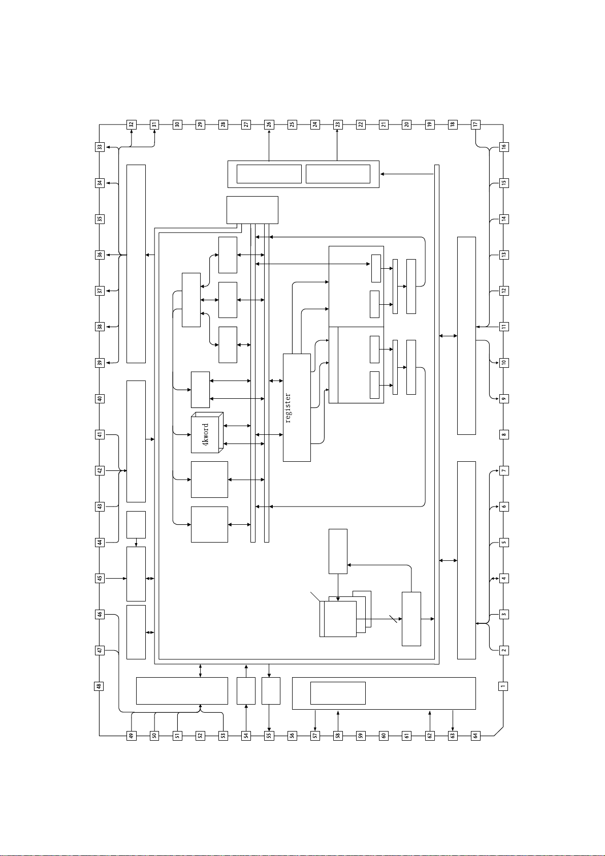
TC94A02F-007
IC BLOCK DIAGRAM
AD10
AD9
VDDT
AD8
AD7
AD6
REQ
VSS
AD11
General
Output Port
AD12
CKS
TESTP
2sets
Address Calc.
ERAM
2k word
VSSR
register
C-Pointer
register
Y-Pointer
register
X-Pointer
VRAR
Bus
DAC
Switch
VDAR
Ro
VDAL
DAC
VRAL
Lo
VSSL
VSS
STANDBY
VDD
/oE
/CE
AD5
LRCKiA
BCKiA
A3
SDi0
AD4
AD3
AX AY
ALU
A2
A1
round & limit
Audio I/F
MAC
MX MY MZ
A0
round & limit
SDo
AD13
AD14
/WR
AD16
AD15
VSS
io0
io1
Flag
Timer
Control
Interrupt
SRAM I/F
I-Bus
Input Port
General
*3
CROM
4k word
YRAM
4k word
XRAM
Prog.
X-Bus
Start
Y-Bus
DIT
X0 X1 X2
Y0 Y1 Y1
PRAM
256word
PROM
VCO
Control
Program
4k*2+2k
=10kword
40bit
Generator
Timing
Decoder
Instruction
Microcom. I/F
VDDT
AD2
/MiCK
MiDio
AD1
AD0
MiMD
/RESET
io2
io3
io4
VDD
io5
io6
io7
VSSP
12
PDo
VCoi
VDDP
CKO
VDDX
Xi
Xo
VSSX
 Loading...