

Viking Pump TSM630.1 User Manual
Electronic copies of the most current TSM issue can be found on the Viking Pump website at www.vikingpump.com
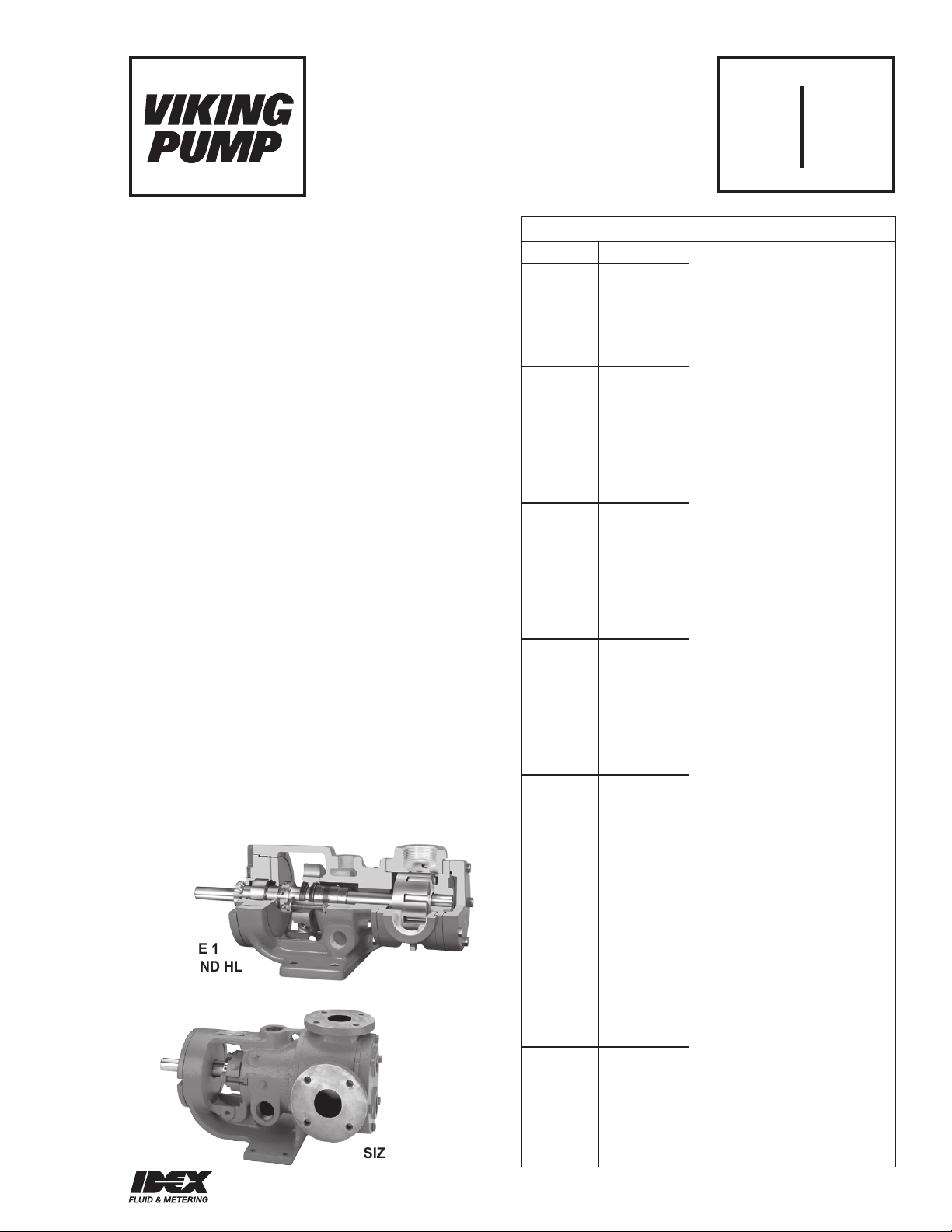
TECHNICAL SERVICE MANUAL
UNIVERSAL SEAL HEAVY DUTY JACKETED PUMPS
SERIES 124E/EH, 224A/AE/AH, 4224A/AE/AH/B CAST IRON
SERIES 226A AND 4226A DUCTILE IRON
SERIES 223A AND 4223A STEEL
SERIES 227A AND 4227A STAINLESS STEEL
SIZES H, HL, K, KK, L, LQ, LL
SECTION TSM 630.1
PAGE 1 OF 14
ISSUE F
CONTENTS
Special Information . . . . . . . . . . . . . . . . . . . 3
Maintenance . . . . . . . . . . . . . . . . . . . . . . 3
Mechanical Seal Pumps . . . . . . . . . . . . . . . . 4
Cartridge Type Optional Stuffing Box Seal . . . . . . . 4
Packed Pumps . . . . . . . . . . . . . . . . . . . . . 6
Optional Behind the Rotor Seal . . . . . . . . . . . . . 8
Thrust Bearing Adjustment . . . . . . . . . . . . . . .10
Installation of Carbon Graphite Bushings . . . . . . . .11
Pressure Relief Valve Instructions . . . . . . . . . . . 11
Heat Cartridges . . . . . . . . . . . . . . . . . . . . .12
INTRODUCTION
The illustrations used in this manual are for identification
purposes only and cannot be used for ordering parts. Obtain
a parts list from the factory or a Viking representative. Always
give the complete name of the part, part number and material
with the model number and serial number of the pump when
ordering repair parts. The unmounted pump or pump unit
model number and serial number are on the nameplate.
In the Viking model number system, basic size letters are
combined with the series number (124E, 124EH, 224A, 4224A,
224AE, 4224AE, 224AH, 4224AH, 4224B, 226A, 4226A,
223A, 4223A, 227A) indicating the basic pump construction
material.
This manual deals only with Series 124E, 124EH, 224A,
4224A, 224AE, 4224AE, 224AH, 4224AH, 4224B, 226A,
4226A, 223A, 4223A, 227A, and 4227A Heavy Duty Jacketed
Bracket Mounted Pumps. Refer to Figures 1 through 12 for
general configuration and nomenclature used in this manual.
Pump specifications and recommendations are listed in
Catalogue Section 630, Heavy Duty Bracket Mounted
Pumps, with Universal Seal Type Bracket.
FIGURE 1
SIZES H AND HL
FIGURE 2
SIZES K, KK AND L
UNMOUNTED PUMP
PACKED MECH. SEAL
H124E
H224A H4224A
H4224B
H226A H4226A
H223A H4223A
H227A H4227A
HL124E
HL124EH
HL224A HL4224A
HL4224B
HL224AH HL4224AH
HL226A HL4226A
HL223A HL4223A
HL227A HL4227A
K124E
K124EH
K224A K4224A
K224AH K4224AH
K4224B
K226A K4226A
K223A K4223A
K227A K4227A
KK124E
KK124EH
KK224A KK4224A
KK224AH KK4224AH
KK4224B
KK226A KK4226A
KK223A KK4223A
KK227A KK4227A
L124E
L124EH
L224A L4224A
L224AE L4224AE
L224AH L4224AH
L4224B
L226A L4226A
LQ124E
LQ124EH
LQ224A LQ4224A
LQ224AE LQ4224AE
LQ224AH LQ4224AH
LQ4224B
LQ226A LQ4226A
LQ223A LQ4223A
LQ227A LQ4227A
LL124E
LL224A LL4224A
LL224AE LL4224AE
LL4224B
LL226A LL4226A
LL223A LL4223A
LL227A LL4227A
UNITS
A = Universal Seal Pump
B = Universal Seal Pump
with mechanical seal
behind the rotor
AE = Universal Seal Pump
with larger rotor shaft
E = Universal Seal Pump with
electric heating
EH = High Speed Universal
Seal Pump with electric
heating
AH = High Speed Universal
Seal Pump
Units are designated by the
unmounted pump model
numbers followed by a letter
indicating drive style.
V = V-Belt
D = Direct Connected
R = Viking Speed Reducer
P = Commercial Speed Reducer
VIKING PUMP, INC. • A Unit of IDEX Corporation • Cedar Falls, IA 50613 USAVIKING PUMP, INC. • A Unit of IDEX Corporation • Cedar Falls, IA 50613 USA
SAFETY INFORMATION AND INSTRUCTIONS
IMPROPER INSTALLATION, OPERATION OR MAINTENANCE OF PUMP MAY CAUSE SERIOUS INJURY
OR DEATH AND/OR RESULT IN DAMAGE TO PUMP AND/OR OTHER EQUIPMENT. VIKING’S WARRANTY
DOES NOT COVER FAILURE DUE TO IMPROPER INSTALLATION, OPERATION OR MAINTENANCE.
THIS INFORMATION MUST BE FULLY READ BEFORE BEGINNING INSTALLATION, OPERATION OR
MAINTENANCE OF PUMP AND MUST BE KEPT WITH PUMP. PUMP MUST BE INSTALLED, OPERATED
AND MAINTAINED ONLY BY SUITABLY TRAINED AND QUALIFIED PERSONS.
THE FOLLOWING SAFETY INSTRUCTIONS MUST BE FOLLOWED AND ADHERED TO AT ALL TIMES.
Symbol
Legend :
!
!
!
!
!
WARNING
!
WARNING
Danger - Failure to follow the indicated
instruction may result in serious injury
!
or death.
BEFORE opening any liquid chamber (pumping
chamber, reservoir, relief valve adjusting cap fitting,
etc.) be sure that :
● Any pressure in the chamber has been completely
vented through the suction or discharge lines or
other appropriate openings or connections.
● The pump drive system means (motor, turbine,
engine, etc.) has been “locked out” or otherwise
been made non-operational so that it cannot be
started while work is being done on the pump.
● You know what material the pump has been
handling, have obtained a material safety data
sheet (MSDS) for the material, and understand
and follow all precautions appropriate for the safe
handling of the material.
BEFORE operating the pump, be sure all drive guards
are in place.
DO NOT operate pump if the suction or discharge
piping is not connected.
DO NOT place fingers into the pumping chamber or
its connection ports or into any part of the drive train
if there is any possibility of the pump shafts being
rotated.
DO NOT exceed the pumps rated pressure, speed, and
temperature, or change the system/duty parameters
from those the pump was originally supplied, without
confirming its suitability for the new service.
BEFORE operating the pump, be sure that:
● It is clean and free from debris
● all valves in the suction and discharge pipelines
are fully opened.
● All piping connected to the pump is fully supported
and correctly aligned with the pump.
● Pump rotation is correct for the desired direction
of flow.
WARNING
WARNING
!
WARNING
!
!
!
WARNING
!
WARNING
Warning - In addition to possible serious
injury or death, failure to follow the
indicated instruction may cause damage
to pump and/or other equipment.
INSTALL pressure gauges/sensors next to the
pump suction and discharge connections to monitor
pressures.
USE extreme caution when lifting the pump. Suitable
lifting devices should be used when appropriate. Lifting
eyes installed on the pump must be used only to lift
the pump, not the pump with drive and/or base plate.
If the pump is mounted on a base plate, the base plate
must be used for all lifting purposes. If slings are used
for lifting, they must be safely and securely attached.
For weight of the pump alone (which does not include
the drive and/or base plate) refer to the Viking Pump
product catalog.
DO NOT attempt to dismantle a pressure relief valve
that has not had the spring pressure relieved or is
mounted on a pump that is operating.
AVOID contact with hot areas of the pump and/or
drive. Certain operating conditions, temperature
control devices (jackets, heat-tracing, etc.), improper
installation, improper operation, and improper
maintenance can all cause high temperatures on the
pump and/or drive.
THE PUMP must be provided with pressure protection.
This may be provided through a relief valve mounted
directly on the pump, an in-line pressure relief valve,
a torque limiting device, or a rupture disk. If pump
rotation may be reversed during operation, pressure
protection must be provided on both sides of pump.
Relief valve adjusting screw caps must always point
towards suction side of the pump. If pump rotation is
reversed, position of the relief valve must be changed.
Pressure relief valves cannot be used to control pump
flow or regulate discharge pressure. For additional
information, refer to Viking Pump’s Technical Service
Manual TSM 000 and Engineering Service Bulletin
ESB-31.
THE PUMP must be installed in a matter that allows
safe access for routine maintenance and for inspection
during operation to check for leakage and monitor
pump operation.
SECTION TSM 630.1 ISSUE F PAGE 2 OF 14

SPECIAL INFORMATION
DANGER !
Before opening any Viking pump liquid
chamber (pumping chamber, reservoir,
relief valve adjusting cap fitting, etc.)
Be sure:
1. That any pressure in the chamber has
been completely vented through the
suction or discharge lines or other
appropriate openings or connections.
2. That the driving means (motor,
turbine, engine, etc.) has been “locked
out” or made non-operational so that
it cannot be started while work is
being done on pump.
3. That you know what liquid the
pump has been handling and the
precautions necessary to safely
handle the liquid. Obtain a material
safety data sheet (MSDS) for the
liquid to be sure these precautions
are understood.
Failure to follow above listed
precautionary measures may result in
serious injury or death.
ROTATION: Viking pumps operate equally well in a
clockwise or counterclockwise rotation. Shaft rotation
determines which port is suction and which is discharge.
Port in area where pumping elements (gear teeth) come out
of mesh is suction port.
PRESSURE RELIEF VALVES:
1. Viking pumps are positive displacement pumps and
must be provided with some sort of pressure protection.
This may be a relief valve mounted directly on the pump,
an inline pressure relief valve, a torque limiting device or
a rupture disk.
2. There are relief valve options available on those pump
models designed to accept a relief valve. Options may
include a return to tank relief valve and a jacketed relief
valve. Pumps equipped with a jacketed head plate are
generally not available with a relief valve.
3. If pump rotation is reversed during operation, pressure
protection must be provided on both sides of pump.
4. Relief valve adjusting screw cap must always point
towards suction side of pump. If pump rotation is
reversed, remove pressure relief valve and turn end
for end.
5. Pressure relief valves cannot be used to control pump
flow or regulate discharge pressure.
For additional information on pressure relief valves, Refer
to Technical Service Manual TSM000 and Engineering
Service Bulletin ESB-31.
Jacketing of the bracket and head provide large chambers at
both ends of the pumping chamber and around the stuffing
box for temperature control of the product in the pump.
SPECIAL MECHANICAL SEALS:
Extra care should be taken in repair of these pumps. Be sure
to read and follow all special instructions supplied with your
pump.
MAINTENANCE
Series 124E, 124EH, 224A, 4224A, 224AE, 4224AE, 224AH,
4224AH, 4224B, 226A, 4226A, 223A, 4223A, 227A, and
4227A pumps are designed for long, trouble-free service life
under a wide variety of application conditions with a minimum
of maintenance. The points listed below will help provide long
service life.
LUBRICATION: External lubrication must be applied slowly
with a hand gun to all lubrication fittings every 500 hours
of operation with multi-purpose grease, NLGI # 2. Refer to
Engineering Service Bulletin ESB-515. Consult factory with
specific lubrication questions. Applications involving very high
or low temperatures will require other types of lubrication.
PACKING ADJUSTMENT: New packed pumps require initial
packing adjustment to control leakage as packing “runs in”.
Make initial adjustments carefully and do not over -tighten
packing gland. After initial adjustment, inspection will reveal
need for packing gland adjustment or packing replacement.
Refer to instructions under “Disassembly” and “Assembly”,
page 7, regarding repacking pump.
CLEANING PUMP: Keep pump as clean as possible. This
will facilitate inspection, adjustment and repair work and help
prevent overlooking a dirt covered grease fitting.
STORAGE: If pump is to be stored, or not used for six months
or more, pump must be drained and a light coat of
light oil must be applied to all internal pump parts.
Lubricate fittings and apply grease to pump shaft extension.
Viking suggests rotating pump shaft by hand one complete
revolution every 30 days to circulate the oil. Tighten all pump
assembly bolts before putting pump in service after being
stored.
SUGGESTED REPAIR TOOLS: The following tools must
be available to properly repair series 124E, 124EH, 224A,
4224A, 224AE, 4224AE, 224AH, 4224AH, 4224B, 226A,
4226A, 223A, 4223A, 227A, and 4227A pumps. These tools
are in addition to standard mechanics’ tools such as openend wrenches, pliers, screwdrivers, etc. Most of the items
can be obtained from an industrial supply house.
1. Soft Headed hammer
2. Allen wrenches (some mechanical seals and set collars)
3. Packing hooks, flexible (packed pumps)
4. Mechanical seal installation sleeve
2-751-002-900 for 1.125 inch seal; H-HL pumps.
2-751-003-900 for 1.4375 inch seal; K-LL pumps.
5. Bearing locknut spanner wrench
(Source: #471 J. H. Williams & Co. or equal)
6. Spanner wrench, adjustable pin type for use on bearing
housing (Source: #482 J. H. Williams & Co. or equal)
7. Brass bar
8. Arbor press
SECTION TSM 630.1 ISSUE F PAGE 3 OF 14

REPAIR: MODELS H, HL, K, KK, L, LQ AND LL
CARTRIDGE MECHANICAL SEAL PUMPS
ITEM NAME OF PART ITEM NAME OF PART ITEM NAME OF PART
1 Locknut 10 Cartridge Seal 19 Idler and Bushing Assembly
2 Lockwasher 11 Capscrew for Bracket 20 Idler Bushing
3 End Cap 12 Grease Fitting 21 Head Gasket
4 Lip Seal 13 Bracket and Bushing Assembly 22 Idler Pin
5 Bearing Spacer Collar (Outer) 14 Bracket Bushing 23 Head and Idler Pin Assembly
6 Ball Bearing 15 Bracket Gasket 24 Capscrew for Head
7 Bearing Spacer Collar (Inner) 16 Pipe Plug 25 Relief Valve Gasket
8 Ring, Half Round (Not H, HL) 17 Casing (Tapped or Flanged) 26 Internal Relief Valve
9 Bearing Housing 18 Rotor and Shaft Assembly 27 Capscrew for Valve
EXPLODED VIEW PARTS FOR SERIES 4224A/AE/AH, 4226A, 4223A, AND 4227A MODELS
DANGER !
Before opening any Viking pump liquid
chamber (pumping chamber, reservoir,
relief valve adjusting cap fitting, etc.)
Be sure:
1. That any pressure in the chamber has
been completely vented through the
suction or discharge lines or other
appropriate openings or connections.
2. That the driving means (motor,
turbine, engine, etc.) has been “locked
out” or made non-operational so that
it cannot be started while work is
being done on pump.
3. That you know what liquid the
pump has been handling and the
precautions necessary to safely
handle the liquid. Obtain a material
safety data sheet (MSDS) for the
liquid to be sure these precautions
are understood.
Failure to follow above listed
precautionary measures may result in
serious injury or death.
CARTRIDGE MECHANICAL
SEAL REPLACEMENT
MODELS:
H, HL, K, KK, L, LQ, LL4224A, 4224B CAST IRON
HL, K, KK, L, LQ4224AH CAST IRON
H, HL, K, KK, L, LQ, LL4226A DUCTILE IRON
H, HL, K, KK, LQ, LL4223A STEEL
H, HL, K, KK, LQ, LL4227A STAINLESS STEEL
For complete pump disassembly and assembly see
pages 7 and 8.
CARTRIDGE MECHANICAL
SEAL REMOVAL
1. Bend up tang of lockwasher and with a spanner wrench,
remove locknut and lockwasher from shaft.
2. Loosen two set screws in the face of the bearing housing
and remove the bearing housing assembly from the
bracket.
3. Remove the pair of half round rings under the inner
spacer collar from the shaft. There are no half round
rings on the “H” and “HL” size pumps.
4. If flush or barrier fluid tubes are connected to the seal
gland, disconnect before removing seal. Loosen the set
screws on the cartridge seal collar to free the cartridge
seal from the shaft. Remove the two gland capscrews
and slide cartridge seal out through bearing housing
opening.
SECTION TSM 630.1 ISSUE F PAGE 4 OF 14
CARTRIDGE MECHANICAL
SEAL INSTALLATION
1. NOTE: Burrs left on shaft can damage O-ring on seal
sleeve during installation. Inspect shaft for burrs and
remove any found with a fine grade of emery cloth.
2. Clean rotor shaft and face of seal chamber.
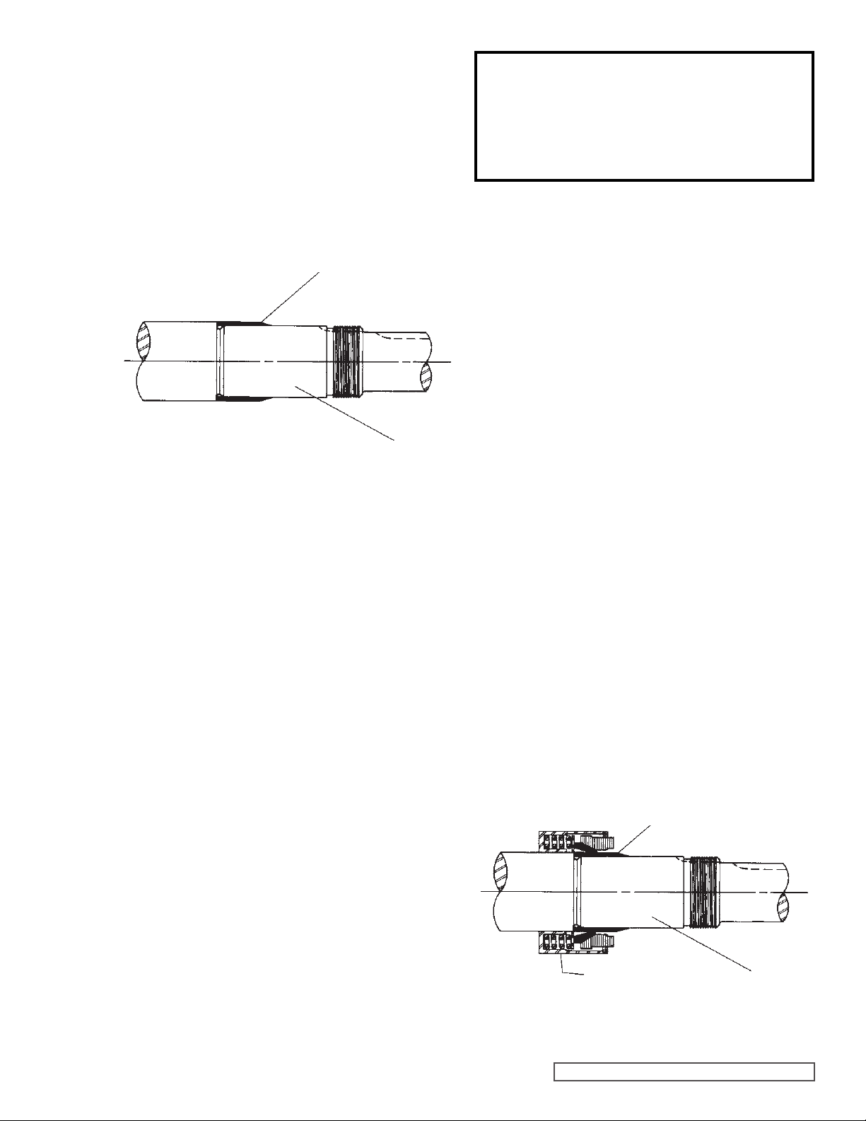
3. Place tapered installation sleeve on shaft. Coat rotor
shaft, tapered installation sleeve, and O-ring in the
inside diameter of cartridge seal sleeve with a generous
amount of light oil. Refer to Figure 4.
TAPERED INSTALLATION SLEEVE
SHAFT
COAT ROTOR SHAFT, TAPERED INSTALLATION
SLEEVE AND INNER DIAMETER OF MECHANICAL
SEAL WITH LIGHT OIL BEFORE ASSEMBLY.
FIGURE 4
4. Slide cartridge seal over installation sleeve on shaft until
it contacts the seal chamber face. Remove tapered
installation sleeve from shaft.
5. Place pair of half round rings in groove on shaft and turn
bearing housing assembly into bracket. There are no
half round rings on the “H” and “HL” size pumps.
6. Put lockwasher and locknut on shaft. Tighten locknut
and bend one tang of lockwasher into slot of locknut.
7. Adjust pump end clearance as in “Thrust Bearing
Adjustment”, page 10.
8. Insert gland capscrews and secure gland to bracket face.
NOTE: turn shaft several turns while gland is loose to
center seal; then tighten gland tight enough to compress
gasket. Tighten only enough to contain leakage and not
to distort gland.
9. Lock cartridge seal drive collar to shaft and remove or
turn centering clips out of the way so as to clear the drive
collar.
10. Turn shaft by hand or jog motor to check drive collar for
runout.
11. Connect flush line or vent stuffing box seals without flush
line until liquid is present on start up.
NOTE: For maximum seal life, flush line should be used.
DANGER !
Before starting pump, be sure all drive
equipment guards are in place.
Failure to properly mount guards may
result in serious injury or death.
ASSEMBLY
OPTIONAL MECHANICAL SEAL
MODELS:
H, HL, K, KK, L, LQ, LL4224A, 4224B CAST IRON
HL, K, KK, L, LQ4224AH CAST IRON
L, LQ, LL4224AE CAST IRON
H, HL, K, KK, L, LQ, LL4226A DUCTILE IRON
H, HL, K, KK, LQ, LL4223A STEEL EXTERNALS
H, HL, K, KK, LQ, LL4227A STAINLESS STEEL
This seal type can be installed as an alternate to the cartridge
mechanical seal. The seal is setscrew driven, is simple to
install and good performance will result if care is taken during
installation.
For complete pump disassembly and assembly, see pages
7 and 8. For Step 6, disassembly, remove the appropriate
nuts, capscrews, seal holder and seal seat. Remove the
pipe plug in the bracket and loosen the setscrews holding the
mechanical seal rotary member to the shaft. This must be
done before the rotor is removed to avoid damage to the seal
and the rotor shaft.
The following steps are for mechanical seal assembly.
1. Clean rotor shaft and seal housing bore. Make sure
they are free of dirt, grit and scratches. Gently radius
leading edge of the shaft diameter over which seal is to
be placed.
Never touch mechanical seal faces with anything except
clean hands or clean cloth. Minute particles can scratch
the seal faces and cause leakage.
2. Place tapered installation sleeve on the shaft. Coat
tapered sleeve and inside of the rotary member
with a generous quantity of light oil. Grease is not
recommended. Start rotary member on shaft and over
tapered sleeve. Refer to Figure 5.
TAPERED INSTALLATION SLEEVE
MECHANICAL SEAL
ROTARY MEMBER
SHAFT
FIGURE 5
SECTION TSM 630.1 ISSUE F PAGE 5 OF 14
 Loading...