

Page 1
VIKING PUMP
Duplex Fuel Oil Packages
Field Start-Up Guide
Bulletin: UDF400
Issued: 2-Oct-06
Page 2

Viking Duplex Fuel Oil Package
Field Start-Up Guide
Before arriving on job site, make sure you have:
A copy of the approved drawing or certified print of the Duplex Fuel Oil Pump Package
A copy of the approved drawing of the Control Panel.
Read all of the instructions, notes, and suggestions in this bulletin to become familiar with the
start-up procedures. If you have any questions or require clarification please contact our
systems specialist, Humberto Da Silva, P.Eng. at (905) 542-8906 ext. 204 (or North America
toll free at 1-888-845-7867 ext. 0 and asked to be transferred)
When you arrive at the site confirm the following:
Check the name plate rating on the Control Panel and compare with the incoming voltage
and motor ratings.
The compound gauge should be located on the pump suction or in the suction header
(depending on pump size and duplex package configuration layo ut).
The pressure gauge should be on the discharge of the pump or in the discharge header
(depending on pump size and duplex package configuration layo ut).
Examine the suction header and confirm that the arrow cast into suction strainer points
toward the pump suction.
Confirm the sales order number stamped on the serial number plate matches the packing
slip. The serial number plate is typically located on the base plate of the unit.
On the control panel confirm the voltage, phase, horsepower, certifications and part number
stamped on the serial number plate located on the door of the panel match the specifications.
Do not open the panel door.
Observations to be made on site:
General Installation
The package should be anchor to the ground to prevent movement. If the unit is mounted on
a shelf it should be properly bolted.
All piping (suction, discharge and relief return lines) should be externally supported to prevent
pipe stresses being transferred to the unit. Ideally flexible connections should be used.
Suction Piping
If possible follow the suction pipe to the supply tank. The suction line should go around
obstacles instead of over them. This is to prevent air lock (the system will not prime if the
suction line is air locked).
If there are any valves on the suction line they should be in the open position.
With long suction pipe there should be a hand operated pump to evacuate the air from the
suction line. This pump should be piped parallel to the duplex package.
The relief valves piping can not be piped back into the suction piping. Both valves can be
piped to a common pipe. But that pipe has to be piped back to the supply tank. There should
not be any other valves in this line. If there is any they should be always in the open position.
Discharge Piping
The discharge will be piped into a day tank or directly into the diesel generator or boiler
depending on the installation.
If possible follow the discharge pipe. If there are any valves on the discharge line they should
be in the open position.
Take a look at the day tank. There should be the line from the duplex pump unit, overflow and
floats.
Bulletin:
Issue:
Page:
UDF400
2-Oct-06
1
VIKING PUMP, INC. • A Unit of IDEX Corporation • Cedar Falls, IA 50613 USA
©2006 VIKING PUMP, INC., All Rights Reserved
Page 3
Viking Duplex Fuel Oil Package
Field Start-Up Guide
Bulletin:
Issue:
Page:
UDF400
2-Oct-06
2
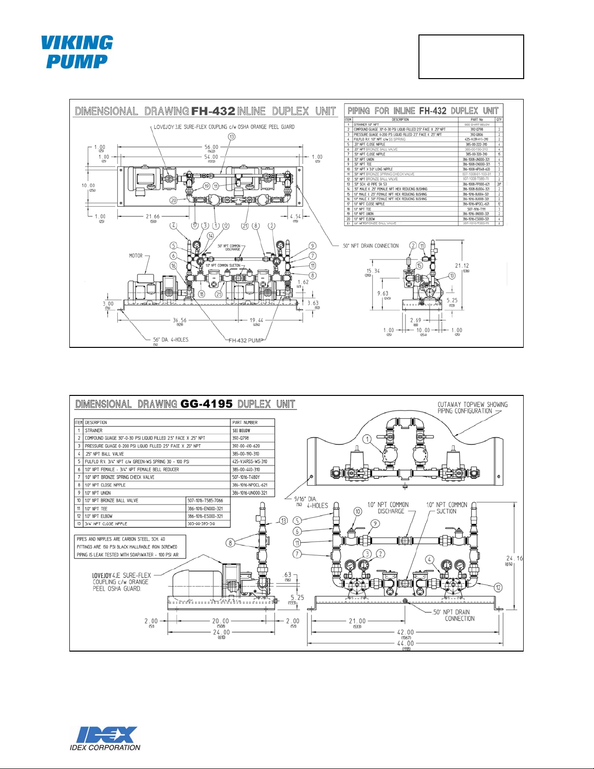
Fig. 1 – Typical F-432 & FH-432 Layout
Fig. 2 – Typical Series 4195 & Spur Gear Layout
VIKING PUMP, INC. • A Unit of IDEX Corporation • Cedar Falls, IA 50613 USA
©2006 VIKING PUMP, INC., All Rights Reserved
Page 4
Viking Duplex Fuel Oil Package
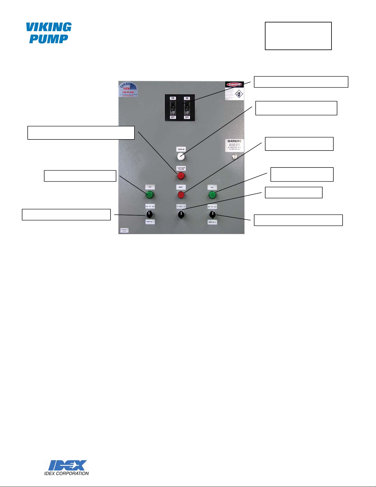
“LEAD PUMP FAILURE” Red Pilot Light
“RUN” Green Pilot Light
“HAND-OFF-AUTO” Switch for P1
Priming the Duplex Fuel Oil Package:
1. On the Control Panel make sure both the Main Disconnect “ON-OFF” switches are in the
“OFF” position (power off).
2. Take a look at the suction gauge to see if there is any pressure on the suction line. If there
is pressure and the application is not a flooded suction the suction line is pressurized.
Carefully remove the drain plug from the basket strainer to release the compressed air.
3. Turn the four ball valves connected to the pressure gauges (suction & discharge gauges)
to closed position.
4. Remove the thumbscrew from top of the lid of the basket strainers, rotate the lid counter
clockwise until the pin hits and stops, and then remove lid.
5. Open the suction valves.
6. Fill the strainers with diesel (the suction valves should be in open position, as you fill one
strainer the liquid level will flow in the other strainer).
7. Reinstall the lid with the tab of the lid just to the left of the boss with the body, rotate the lid
clockwise until the holes line up, and reinsert the thumbscrew.
8. Both the suction and discharge ball valves should be in open position.
Field Start-Up Guide
Fig. 3 – Typical Control Panel Cover
Bulletin:
Issue:
Page:
Main Disconnect Switches “ON-OFF”
“POWER ON” White Pilot Light
Manual “RESET” Button
“RUN” Green Pilot Light
“P1-AUTO-P2”
“HAND-OFF-AUTO” Switch for P2
UDF400
2-Oct-06
3
VIKING PUMP, INC. • A Unit of IDEX Corporation • Cedar Falls, IA 50613 USA
©2006 VIKING PUMP, INC., All Rights Reserved
Page 5

Viking Duplex Fuel Oil Package
Field Start-Up Guide
Bulletin:
Issue:
Page:
UDF400
2-Oct-06
4
9. On the Control Panel, turn the “Hand-Off-Auto” selector switches to “Off” position for both
P1 and P2.
10. Turn both the Main Disconnect “On-Off” switches to “ON” position (power on).
11. Turn the “P1-Auto-P2” switch to “P1” position.
12. Have some one observe the motor fan for the next operation.
13. For P1 turn “Hand-Off-Auto” selector switch to “Hand” position and P1 will start.
14. After approximate 3 seconds turn the “Hand-Off-Auto” selector switch for P1 back to “Off”
position.
15. Confirm that the motor fan had spun in the proper rotation. If the motors are not rotating
properly have an electrician switch the motor leads and check again the rotation of the
motors.
16. Repeat steps 11 to 15 for P2.
17. Turn the four ball valves connected to the pressure gauges (suction & discharge gauges)
to the open position.
18. For P1 turn “Hand-Off-Auto” selector switch to “Hand” position and P1 will start.
19. Observe the suction compound gauge; it should start pulling a vacuum. The discharge
gauge will read 0 psi. Run P1 for no more than 2 minutes then turn it off. Place you hand
on the pump (around the seal area) and if it starts heating up, turn off the pump to prevent
mechanical seal failure.
20. When the pumps are primed and pumping the discharge gauge will show a positive
pressure.
NOTE: If the suction line is long you may have to refill the basket strainer again. Before this is done the
suction valves will have to be in the closed position, other wise the vacuum will be lost. Then alternate
running P1 and P2 in manual mode.
NOTE: Some local codes specify a anti-siphon valve to be installed on the suction line. It is usually
installed close to the main supply tank. In some cases this valve will prevent the pumps from priming. If
the pumps don’t prime after a few attempts ask the contractor to loosen the spring in the anti-siphon valve
and then after the pumps are primed the spring can be set in order to meet local cod es.
NOTE: If the installation has a flooded suction, turn the suction and discharge valves to the open
position. The suction pressure gauge should show a positive pressure. If it doesn’t follow the suction line
to the supply tank and see if all the valves are open. If all the valves are open and the pressure gauges
don’t read a positive pressure there a blockage in the line. The blockage will have to be cleaned before
running the pumps.
VIKING PUMP, INC. • A Unit of IDEX Corporation • Cedar Falls, IA 50613 USA
©2006 VIKING PUMP, INC., All Rights Reserved
Page 6

Viking Duplex Fuel Oil Package
Field Start-Up Guide
Bulletin:
Issue:
Page:
UDF400
2-Oct-06
5
CONTROL PANEL
Check the name plate rating of the Control Panel and compare with the incoming line voltage and
the motors ratings.
Adjust overload relay setting to full current rating
Check that motor protector push actuator(s) is (are) in start position.
Check that float switches are adjusted to the desired levels
Check that the controller is properly connected to the pump motors
If motors are rotating in the proper direction (as checked in steps 10 to 16 under Priming section),
and all the above checks out correctly, turn the “Hand-Off-Auto” switches for both P1 and P2 to
the “Auto” position.
Activate float switches manually and test if the pumps start and stop at desired levels.
Once the level falls below the start lead pump level float switch FL2 (as shown in diagram under
Float Controls), the pump motor is energized and the lead pump starts pumping fuel into the tank.
If the lead pump has failed and the level falls below FL2 start lead pump level float switch, the
“Lead Pump Failure” red pilot light is turned on and the lag pump motor is energized so that the
lag pump keeps pumping fuel into the fuel tank.
In order to turn off the “Lead Pump Failure” red pilot light, the manual “Reset” red pushbutton
must be pressed.
Once the level reaches the stop all pumps level float switch FL3, the pump motors are de-
energized and the pumps stop.
If the alternation selector switch “P1-Auto-P2” is in the “Auto” position, the stop all pumps float
switch FL3 triggers the alternator and reverses the order of the lead and lag pumps. For
example, if P1 was the lead pump before the trigger, P2 will become the lead pump after the
trigger.
RELIEF VALVES
Checking Relief Valves Current Setting
1. With the pump running notice the reading on the discharge pressure gauge.
2. Slowly close the discharge ball valve.
3. Operate only one pump at a time in manual mode.
4. The reading on the discharge pressure gauge will increase.
5. Make a note of the pre ssure reading when the valve is fully closed; this value is the pressure
relief valve setting. It should be approximate 15 to 20 psi greater than the specified pump
discharge pressure.
6. Open the discharge valve and turn the pump off.
7. If the pressure relief setting in satisfa cto ry, repeat for the other pump.
VIKING PUMP, INC. • A Unit of IDEX Corporation • Cedar Falls, IA 50613 USA
©2006 VIKING PUMP, INC., All Rights Reserved
Page 7
Viking Duplex Fuel Oil Package
Field Start-Up Guide
Bulletin:
Issue:
Page:
UDF400
2-Oct-06
6
Setting the Pressure Relief Valves
1. Turn the “Hand-Off-Auto” switches to “OFF” for both P1 and P2.
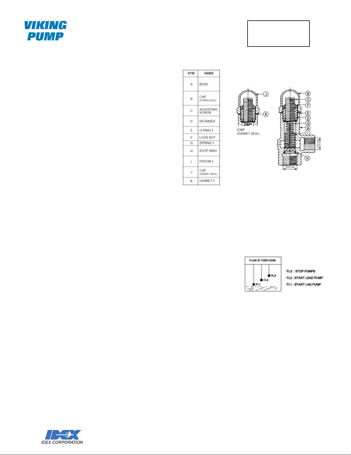
2. Remove the cap (item J) of the
pressure relief valve for pump P1.
3. Loosen the lock nut (item F)
4. Turn the adjusting screw (item C)
clockwise to increase the pressure
setting or counterclockwise to
decrease the pressure setting
5. Tighten the lock n ut (item J)
6. Reinstall the cap (item B) onto the
valve.
7. Turn the “Hand-Off-Auto” switch for
P1 to “HAND” position.
8. Slowly close the discharge ball valve
for P1. If the pressure relief setting is
not satisfactory repeat the operation t
o
adjust the adjusting screw.
9. Repeat step s 1 to 8 for pump P2.
FLOAT CONTROLS
The standard duplex control panel contains NC relays to operate three f
switches (switches supplied by others) for the day tank. If more than three
floats are required, the control panel would have to be ordered with
optional NC relays.
The top float (FL3) stops both pumps, the middle float (FL2) starts the lead
pump and the bottom float (FL1) starts the lag pump.
It may not be practical to fill the day tank to test the operation of the panel. A simpler way is to have the
electrician simulate the open and closing contacts of the floats to check the operation sequence. Thi s
procedure can be used to check the high and low level alarms (if supplied) in the panel. The electrician
can check the conductivity of the float (normally open or normally closed) to see if they are the same as
specified. In some cases there is no day tank and the pump duplex unit pumps directly into the diesel
generator or boiler. The panel will receive the signal from the generator and start the lead pump.
loat
VIKING PUMP, INC. • A Unit of IDEX Corporation • Cedar Falls, IA 50613 USA
©2006 VIKING PUMP, INC., All Rights Reserved
Page 8

Viking Duplex Fuel Oil Package
Field Start-Up Guide
Bulletin:
Issue:
Page:
UDF400
2-Oct-06
7
PRESSURE SWITCHES
If the duplex unit is supplied with pressure switches (either single or dual stage) they will be installed on
the discharge line. The pressure setting will be factory set, but they are field adjustable.
To simulate a low pressure condition on the discharge line, have the control panel on automatic mode
and then close the discharge valve of the pump running. The relief valve will open and the pumping liquid
will return to the supply tank. The pump will shut down and a red light will come on the panel, the time will
be that is set on the timer.
It is difficult to simulate an actual high pressure shut down. Have the electrician simulate by open or
closing the contacts in the control panel.
Field adjustment of the pressure setting can be done by the following:
Single Stage Pressure Switch – Square D – 9012-GNG2
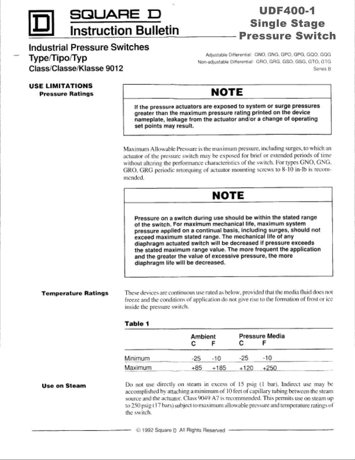
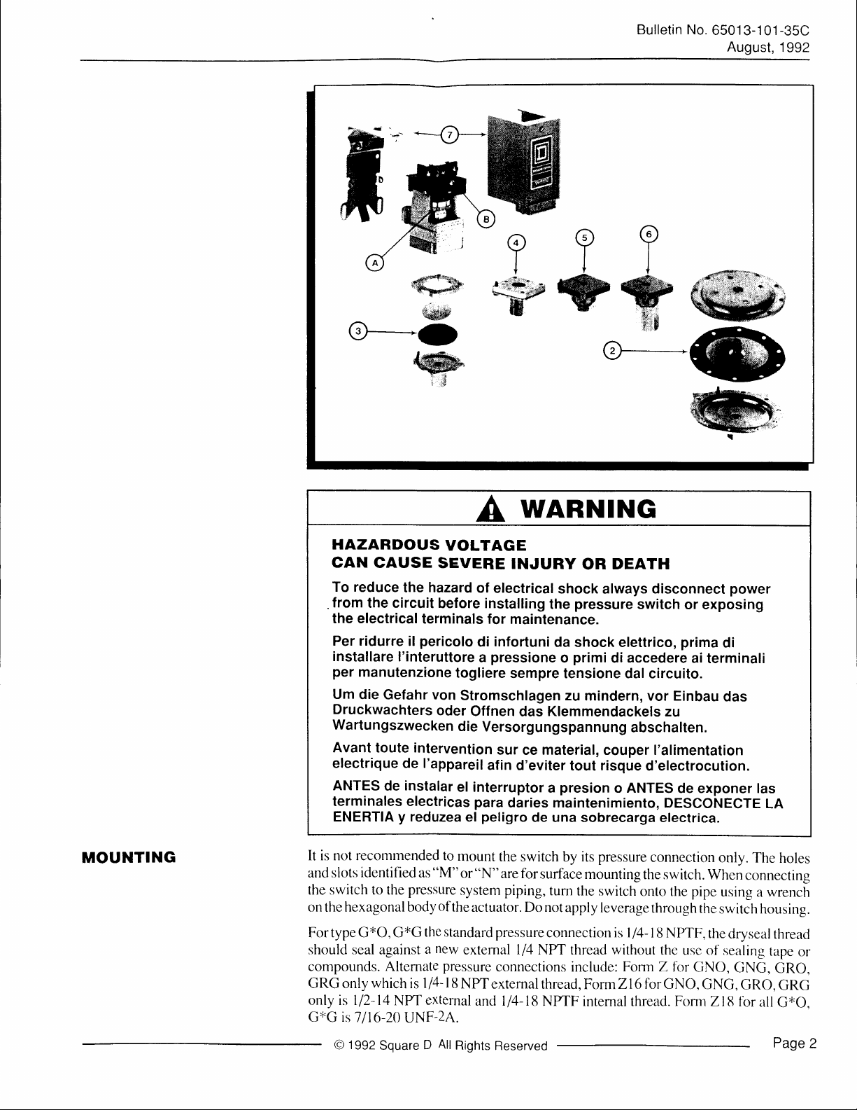
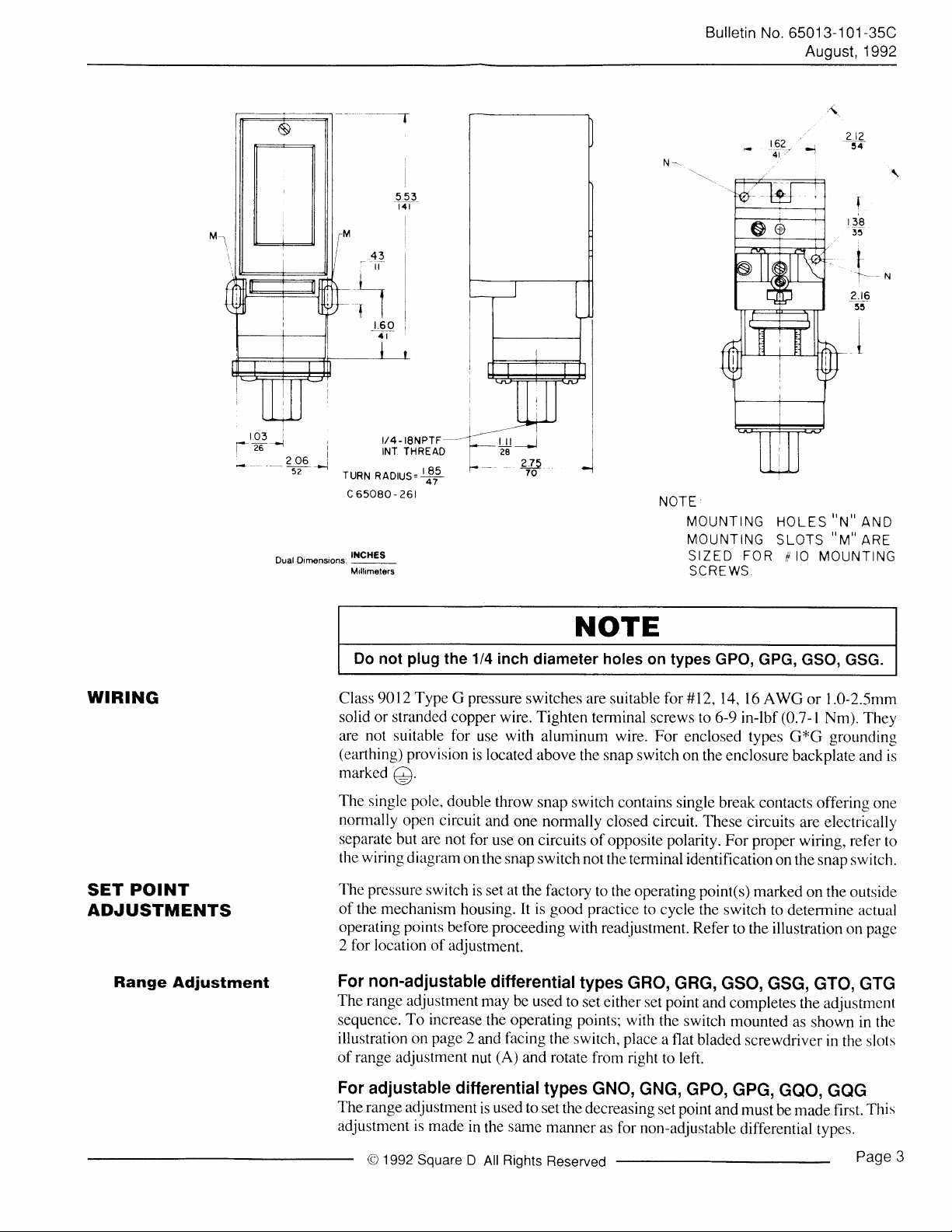
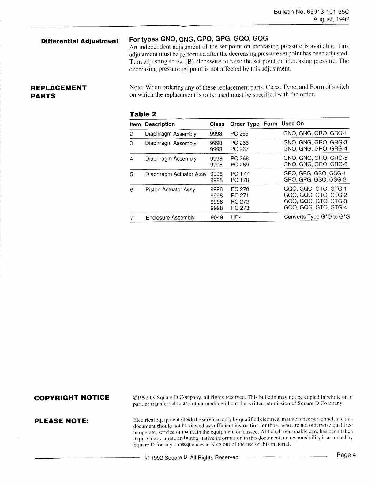
See UDF400-1 Single Stage Pressure Switch.pdf
Dual Stage Pressure Switch – ASCO – SC10D-TG10A21
See UDF400-2 Dual Stage Pressure Switch.pdf
FLOW SWITCHES
If the duplex unit is supplied with a flow switch it will be installed on the discharge line. To simulate a low
flow condition on the discharge line, have the control panel on automatic mode and then close the
discharge valve of the pump running (either P1 or P2). The relief valve will open and the pumping liquid
will return to the supply tank. Within a few minutes (usually 1 to 3 minutes) based on the time set on the
timer, the control panel will start the other pump and the “Low Flow” Signal red lights (optional equipment
required for installation of low flow switch) will light up on the panel.
VIKING PUMP, INC. • A Unit of IDEX Corporation • Cedar Falls, IA 50613 USA
©2006 VIKING PUMP, INC., All Rights Reserved
Page 9
UDF400-1
Single Stage
Pressure Switch
Page 10
Bulletin No.
e9
tt
6501
3-1 01
August,
-35C
1992
Ssw
Ns
o--.-(D
t
;J
A
HAZARDOUS
CAN
CAUSE
To reduce
from
the electrical
Per ridurre
installare
per
manutenzione
Um
die
Druckwachters
Wartungszwecken
Avant
electrique de I'appareil
ANTES
terminales electricas
ENERTIA y reduzea
the hazard
the circuit
l'interuttore a pressione
Gefahr von
toute intervention
de
VOLTAGE
SEVERE
of electrical
before installing
terminals for
pericolo
il
instalar
di
togliere
stromschlagen zu
oder
Offnen
die
el interruptor a presion
para
el
Versorgungspannung
peligro
€Rr
@-
wARNING
INJURY
shock always disconnect
the
maintenance.
infortuni
sempre tensione dal
sur
afin d'eviter
daries maintenimiento,
da
o
Klemmendackels
das
material,
ce
tout
de una sobrecarga
DEATH
OR
pressure
shock elettrico,
primi
di
mindern, vor Einbau
couper I'alimentation
risque
o ANTES
F.:$
W
{W
W
switch
accedere
abschalten.
or exposing
prima
ai
terminali
circuito.
zu
d'electrocution.
de
exponer las
DEScoNECTE
electrica.
power
di
das
LA
MOUNTING
It is not recontmended to
and slots identified
the switch to the
hexagonal body
on the
For type GxO, G*G
should
compounds. Altemate
GRG
only is ll2-14
G*G isl
O
against
seal
which
only
116-20 UNF-2A.
1992
Square
"M"
as
pressure
the
new
a
l/4-
is
external
NFrf
D
of
standard
pressure
l8
All
mount
the
Rights
the switch
"N"
or
are for
system
extemal
NFrf
piping,
actuator. Do not
pressure
l/4
connections include:
external
and ll4-18
Reserved
pressure
its
by
surface
NFrf thread
thread,
NFrfF
mounting
tum
the
switch
apply
leverage
connection is
Form
intemal thread.
connection
the switch.
onto the pipe
through the
I
NPTF.
14-18
without
the usc
Fonn
Z fc>r
Z16forGNO,
Fonn
only.
When
using
switch
the
dryseal
of sealing
GNO,
GNG,
GNG,
Zl8
for
The
holes
connecting
wrench
a
housing.
thread
tape
or
GRO,
GRO,
GRG
all
G*O.
Page
2
Page 11
Bulletin
No. 6501 3-1 01
-35C
August, 1992
(
t03
i*ze+
l
206
i
-52 --l
Dual Dimensions
ruRN
RADtus=$
c
65080 - 26 I
lXcH€s
MailameleI
r/4 - TSNPTF-=
INT THREAD
lr
2A
J
275
70
NOTE
MOUNTING
MOUNTING
SIZED
SCREWS
162
-cr
HOLES,'N''
SLOTS
FOR
IO MOUNTING
#
-1
''
?.t2
.T
t38
3t
?r9
M"
I
I
t
l-..-
55
I
I
I
AND
ARE
N
WIRING
POINT
SET
ADJUSTMENTS
Range
Adjustment
Do not
Class 9012
solid
are
(eanhing)
marked
The single pole,
normally
separate
the
The
of the
operating
2 for location of
For non-adjustable
The
sequence.
illustration on
range
of
plug
the 1/4 inch
Type G pressure
or stranded copper
not
suitable for
provision
@.
double
open circuit
but are
wiring
pressure
mechanism
not
diagram
switch
points
before
for
on
housing.
adjustment.
range
adjustment
To increase
page
2
adjustment
use with
is located
throw
and
use
the
set
is
proceeding
differential
may
the
and
(A)
nut
NOTE
diameter
switches
wire. Tighten
aluminum
above
snap switch contains single
one normally closed circuit.
circuits
on
snap switch
at
the
factory
good practice
It is
be used
operating points;
facing
the
and rotate
holes
on types GPO,
are suitable
for #12,14,16
terminal screws to
wire.
For
the snap switch on the
of opposite
not
the terminal identification
to the
polarity.
operating point(s)
to cycle
with
readjustment.
types
to
switch, place
GRo,
set
either set point
with
from
right
the
a flat
to left.
GPG,
AWG
6-9 in-lbf
enclosed types
enclosure
break contacts
These
circuits
proper
For
marked
the switch
Refer
to the illustration
GRG,
GSo,
and
completes
switch
mounted
bladed
screwdriver
GSO, GSG.
or 1.0-2.5mm
(0.7-
I Nm).
grounding
G*G
backplate
offering
are electrically
wiring, refer
on the
snap switch.
on the outside
to
determine actual
on
GSG,
GTo,
the
adjustmcnt
as
shown in the
in
the slots
They
and is
one
to
page
GTG
For
adjustable differential
The range adjustment
adjustment is made
1992
O
Square D
in
is
the
All
used to
same
Rights
types
set
GNO,
the
decreasing
manner
Reserved
GNG,
as for non-adjustable
set
GPO,
point
and
GpG,
must
differential
GeO,
GOG
be made first.
types.
Page
This
3
Page 12
Differential
Adiustment
types
For
inclependent
An
adjustment
Tum
decreasing
must
adjusting
pressure
GNO,
adjustment
be
screw
GPO,
GNG,
of
perfonned
(B)
set
after the
clockwise
is
point
GPG,
set
the
to
not
affected by
GQO, GQG
point
decreasing
raise
increasing
on
pressure set
set
the
this
Bulletin
No.
6501 3-1 01
pressure is available.
point has
been adjusted.
point on increasing
adjustrnent.
-35C
August,
1992
This
pressure.
The
REPLACEMENT
PARTS
When ordering
Note:
which the replacement
on
any
Table 2
Description Class
Item
Diaphragm Assembly
2
Diaphragm
Diaphragm
Diaphragm
Piston
Enclosure
Assembly
Assembly
Actuator Assy 9998
Actuator Assv
Assemblv
of these replacement
must
is to be
used
9998
9998
9998
9998
9998
9998
9998
9998
9998
9998
9049
Order
PC
PC 266
PC
PC 268
PC 269
PC
PC
PC 270
PC 271
PC
PC
UE-1
parts. Class,
be
Type
265
267
177
178
272
273
spccified
with the order.
Form Used
Forlr of
and
Typ",
On
GNO, GNG,
GNG,
GNO,
GNO, GNG,
GNO, GNG, GRO,
GNO, GNG,
GPG, GSO, GSG-1
GPO,
GPO, GPG, GSO, GSG-2
GOG, GTO, GTG-1
GQO,
GQG, GTO, GTG-2
GQO,
GQG, GTO, GTG-3
GQO,
GQG, GTO.
GQO.
Converts
Type
srvitch
GRG-1
GRO,
GRO, GRG-3
GRG-4
GRO,
GRG-s
GRO, GRG-6
GTG.4
G.O to G.G
COPYRIGHT
PLEASE
NOTE:
NOTICE
@1992
part, or transf'erred
Electricalequipment
document
to operate,
to
Square
provide
D
1992
e
should
service
accurate
for any
to
should
be viewed
not
ntaintain
or
and
consequences
Square
Company,
D
Square
by
any
D
all rights
media
other
be serviced
as
the equipmcnt
authoritative
arising
All
Rights
reserved.
without thc
qualified
only by
sufficient
information
Reserved
instruction
discussed. Althclugh
in
out of the use of this
This bullctin may not be copied in
perntission
writtcn
e lcctrical
tliose
tor
this documcnt,
matcrial.
of Square D Contpany.
Inaintenance
who are
reasonablc
responsibility
no
pcrsonrlcl. and
not otherwise
carc has bee n takcn
is assLrrncd
whole
qualifiecl
Page
or
in
this
by
4
Page 13
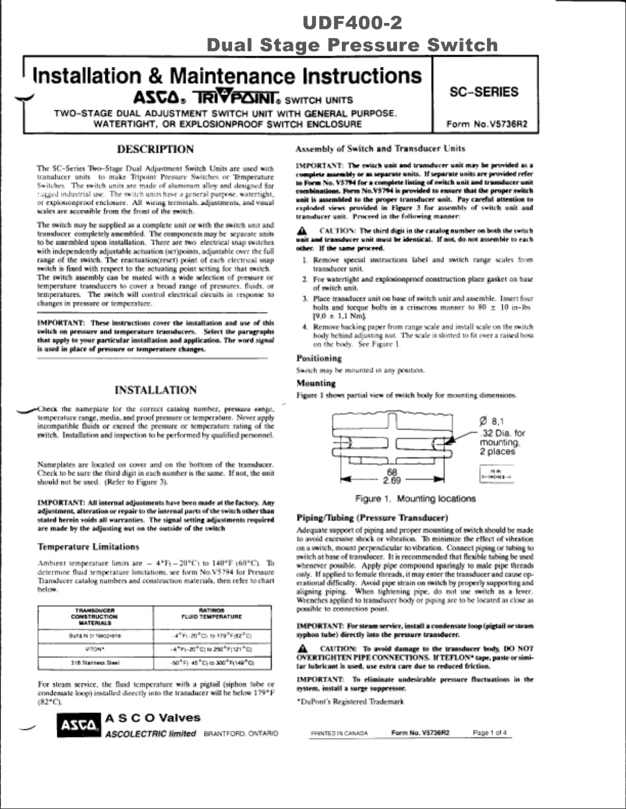
UDF400-2
Dual Stage Pressure Switch
Page 14
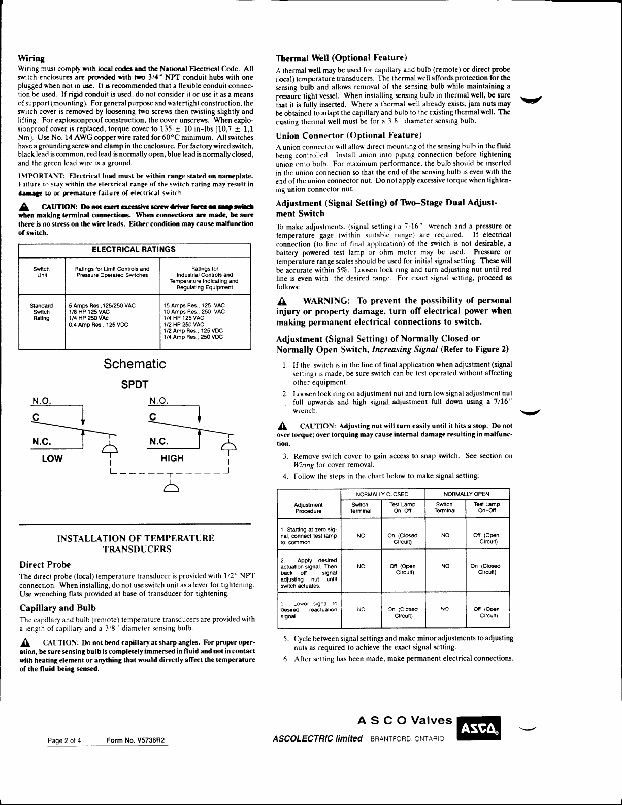
Wiring
Winng
must comply
enclsurer arc prcrrdcd
snrrtch
rhcn
plugged
tion bc urd. If ngid
of
support
s*'itch cover is remored by loosening two screps then tvristing
lmounting).
lifting. For exploeionprmf construction, the cover
sionproof cover is replaced,
Nml. Use
have a
black
and
IMPORTA\iT: Electrical load
Failure
dt-ra"
A
vien making terminal connections.
th€re
No. 14 AWG copper
grounding
lead is
the green
to
slay
!o
CAUTION:
is
no
ol switch.
SY/ltch
Unlt
Standald
slMlch
Ratlng
rrth
loc-l codcs end thc
witb
r.rsc.
not in
It is recommended
conduit is
For
screw and clamp
common,
or
red lead is normally open,
wire
lead
*ithin
is a
the
electrical range
poematurr failurt of electrkal sritch.
two 3/,t' NPT conduit
used, do not consider
general purpoce
torque
coverlo 135
wire
raled for 60oC
lhe
in
enclosure . For factorywired switch,
ground.
must
within
be
of the
and
IlordcrrrcrcsCwscrwffrrfrrlr-E
Vyhen conncc{ions erc medc,
stness on the
wirc
leads. Either condition
ELECTRICAL RATINGS
Ratlngs tor Llmll Controls and
Pressure OD€rat9d S\Mtches
Ros., I 251250
5 Amps
HP 125 VAC
1/8
1/4 HP 250 vAc
0.4 AmD Res.. 125 VDC
VAC
EhctricalCode.
Natkroal
hubs
that
a flexible conduit connec-
it or use it as a means
walertighl
unscrews.
+
in-lbs
10
construction, the
minimum. All switches
blue lead is normallyclosed,
rang€ stated on
s*itch rating
mav result in
mey caus€
Ratlngs for
Induslrlal Conlrols and
Temp€ralur€ lndlcalhg and
Begulatlng Equlpment
Amps
Amp
250
125
Res
25O
,
VAC
Res., 125 VDC
vOC
15Amp6 Res.,
10
l/4 HP 125VAC
1/2 HP
112
1/4 Amp B€s., 250
Schematic
SPDT
N.O.
with
one
slightly and
When
explo-
r-
[10,7
nameplate.
rll
be surc
malfunction
VAC
VAC
All
1,1
(Optional
Thermal
A
1.aal)
snsing
Fressure
rirat it is
bc obtained
ensting
Union
A
being
union
in
end
ing
Adjustment
ment
'Io
lemperalure
conneclion
batlery
tempe
be
line
Well
well
lempe
bulb
tight
fully
may
ralure
allows
and
vessel.
inserted.
thermal
lo adapt
well
thermal
Connector
union conneclor
controlled.
onlo bulb. For
union conneclion
the
of
union
the union
connector
conneclor
(Signal
Switch
adjustments,
make
gage
(lo
line
powered tesl lamp
range
ralure
within 5%. l,rn.:rn
accurate
wilh the desired
is even
be used
transducen.
When installing
the capillary
musl
*rll
Inslall union
maxrmum
nul.
(within
of final
scales should
follows:
WARNING:
A
iqiury
making
Adjustrnent
Normally
1. If
property
or
permanent
(Signal
Open
the swrtch is in
is made,
setting)
S*itch,
be sure
olher equipment.
lock nng on
l-oose n
2.
full uprrards and high
,
wlcnch.
CAUTION:
A
over torque; over torquing
tion.
3. Remove
l4/iing
4.
Follow
Adlustment
Procedur€
Adjusting nut
cover
switch
cover removal.
for
step in the chart
the
Feature)
for
The
of
removal
thermal
Where a
and
a 3
be for
(Optional
allo* direcl
mounting
into
prrformance
the
lhal
so
Do not apply
nut.
Setting)
(signal
se tting) a
suitable
application)
ohm meler may
or
be used for
lock
range. For
prevent
To
damage, turn
electrical
Setting)
well
thermal
the
rnsrng
affords
bulb
rnsing
bulb in lhermal
rcll
already exists,
bulb to the e xisting
8' drameler rnsing
Feature)
the
of
piping connection
the bulb should
,
the sensing bulb is even
of
end
excessive torque
Tlvo-Stage Dual
of
7116 " wrench
are required. If
range)
of the swrtch
initial signal
ring and lurn adjusting
exact signal
possibility
the
ofT electrical
connections
Normally
of
(remote)
and bulb
capillarl
Increasing Signal
the line of finalapplication
swilch can
adjuslmenl
sig,oa-l
may caus€
gain
to
NORMALLY
SrMtch
Termlnal
be lesl operated
nul and lurn low signal
adiuslment fu!
wilt
turn easily
internal damage
access lo
below lo make
CLOSED
Tesl Lamp
On-Ofl
until it hits a stop. Do not
snap switch. See seclion on
Tormlnal
prolection
while
the rmal
for the
maintaining
well,
be sure
jam
nuts may
well.
The
probe
or direct
bulb.
rnsing
before
bulb
fluid
tightening
in the
be inserted
with
when
tighlen-
A{iust'
pressure
and a
electrical
is
desirable,
not
be used. hessure or
se tting.
These
nul until red
proceed
setting,
personal
of
power
when
to switch.
or
Closed
(Refer
when
signal setling:
NORMALLY OPEN
SrMlch
Figure 2)
to
adjuslment
withoul
(signal
affecting
adjustment nul
Tesl
On-Olt
a 7/16"
Lamp
down using
resulting in malfunc-
a
V
the
or
a
will
as
\/
INSTALI.-{TION
Probe
Direct
probe
direct
The
conneclion.
Use
Capillary
The capillary and
a length
A
ation,
with heating
of the fluid
When
wrenching flats
and
of capillary and a 3/8
CALTIOIi: Do not
be sure se nsin3
element or anythint
being scnsed.
Page 2 o{
TRANSDUCERS
(local)
temperalure
inslalling,
Bulb
bulb
4
do nol
provided
at base of
(remole)
"
bend capillary
bulb is completely
Form No. V5736F2
TEMPERATURE
OF
lransducer is
use swilch unit as
transducer for
provided
a lever for
tighlening.
temperalure lransducers
diameter
sensing bulb.
at sharp angles.
immersed in fluid
would directly affect
that
with
1/2" NPT
lightening.
wilh
provided
are
properoper-
For
and not in contact
the temp€rature
1
Slarthg at zsro
nal,
conn€ct
lo
common
2 Apply
acluatlon slgnal.
back
adlustlng nul
swltch acluales.
:
d€dreo
slgnal.
5. Cycle
lest
.
oft slgnal
srgna
-ow€f
roetualixl
betwee
lamp
deslred
Then
nuts as required
selling has
Afler
ASCOLECTRIC
slg-
untll
lo
n signal
lo achieve
been made, make
limited
NC On
NC Oll
se tlings
(Clo6€d
Clrcun)
(Open
Clrcult)
Cn
iclo's€c
Clrcun)
and make minor
the exact
signal setting.
permanenl eleclrical connections.
A
S C O
BRANTFORD. ONTARIO
Valves
NO Olf
NO On
|lo
Clrcull)
dl tooen
adjustments to
(Open
Clfcutl)
(Clo€ed
Clrcutl)
adjusling
Page 15
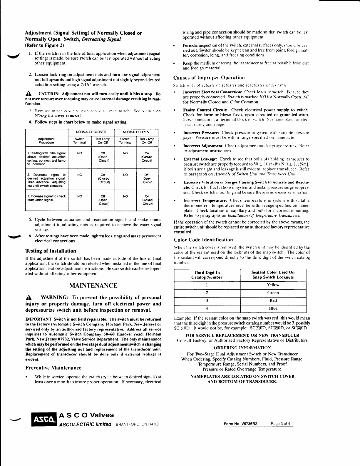
J
yl
Open
Figure 2)
to
(Signal
Switch,
Setting)
Decreasing
final application
Normally
of
be
Signal
lest
Closcd or
when
ope rated
ad;ustnrnt
rrthout
Adustment
Normafly
(Refer
1. If the wnlch is in the line of
selting) is made, be sure switch can
other equipment.
2. Loosen lock ring on adjustment nuts
nut fullupwards and high signaladjustment
and lurn lory signal
nul slightty beyond
actuation setting using a 7/16" wrench.
CAUTION: Adjustment nut will turn easily until it hits a stop.
A
not over
torque;
over
torquing
may cause internal damage resulting
fu nction.
] RemOVC
4.
1.
Startlngwilh
above deslred actuatlon
s€ttlng, connect t€sl lamp
lo common.
2. D€crease slgnal
d€slred acluatlon
Th6n
nul untll swltch acluales.
Incraas€ slgnal locheck
3.
roacluallon
5. Clcle between actuation and reactuation signals and
6. Alter scltrngs
Testing
the adjustment of the switch has been
If
applicalion, the swilch should be retesled
application. Follow adjustment instructions. Be sure swilch
ated
$i:.'h
i|'"nng
fur COv€r re rotrral
Follo* stcps
Adluslm€nt
Procedure
Inltlal
slgnal
advanc€ adJustlng
adjustment to adjusling nuls as
seltinqs.
electrical conneclions.
without
slgnal.
slgnal.
Installation
of
affecting olher
'\i
Carrcr
charr
in
lo
haw bccn ma&,
3iCcr.
irin
bclo* to makc signal rtting.
NORMALLY CLOSED t{c)RMALtY
Swllch
T€rmlnal
NC ofl
NC
NC otf
trghten
equipmenl.
Tosl
On-Ofi
(Open
Clrcull)
(Closed
Clrcull)
(Open
Clrcun)
required
On
.rr:lCh
l,'.::rl
Lamp
S\./tlch
Termlnal
Sce:t'Ctr()n
^to
NO
NO O;t
to
lock rings and make perrnanenl
made outside of
when
inslalled in lhe line of final
achieve
the
the
can be test oper-
MAINTENANCE
WARNING: To
A
iqiury
or
property
prevent
damage, turn
depressurize switch unit b€fore
IMPORTANT:
to the factory
only by
serviced
inquiries to Automatic
Park, New
which may be
the setting
Replacement of transducer should be done only if external
evident.
Jersey
of the
is not field repairable. The switch must be returned
Switch
(Automatic
an authorizd factory repres€ntative. Address all service
07932, Valve
performed
adjusting nut and
Company. Florham Parlq New
Switch
Company, 50-60 Hanover road, florham
Switch
Service
on the two stage dual adjustment switch is changing
Preventive Maintenance
.
While
service,
in
leasl once a month
operale
lo
insure
the
s\r'itch
prop€r ope ralion. If necessary, electrical
possibility
the
of
off electrical
inspection
D€partment. The only mainte nance
replacement of the transducer unit.
benree n desired signals)
tcycle
removal.
or
lsignal
affecting
ad;ustmenl
desired
in
nal-
Cp€\
T6l
i_.Jng
Cn-Clt
Or
tfu.d
CrqJn)
dl
rOgcn
Qtrattl)
(Clo3€d
Clrcun)
make minor
exact signal
line of final
personal
power
and
Jersey)
leakage is
Do
On
.
.
Causes
S*itch
.
.
.
.
.
.
.
lhe ope ration of the switch cannol
If
enlire
consulted.
Color
Wtren
color
lhe sealant
number.
Example:
thal the third digit in the
or
SC30D. It
Consult
at
wiring and
operated
Periodic
ried out.
ler, corrosion,
Keep
and foreign
Inco<rtct Elcctrkd
are
for Normalty
fbultl
Check for loose
itxrsc ctrnnections
trical ratrng and ranqc.
Incorrtct
gaRe. hessure
lrqrtct
to
Er&ynrl
pressure swilchare
If
to
Ercessive
ate: Check for fluctualrons
sor. Check
Incorrtrt
lhermometer. Temprrature musl be
plate.
Refer
of lhe sealanl
pipe conneclion should be made
withoul affecting
inspeclion
Swilch
the
medium
Improper Operation
of
*rll
nt-rl aclusle
prope rly connecled.
Control Circuic
ad;ustme nl tnstruclions.
boits are
paragraph
Check
to
pnragraphs
unit
switch
Code
the s*ilch
*-ill
Third
Catalog
of the
should
and freezing conditions.
icing,
enlenng
nal
male
()r
aclu31e5 and re:iiu-itcs
C6o.cti(r:
and C for Common.
Clced
or blown fuses, open-circuiled or
at terminal
Prcsurt:
Adjosrrnt: Check
lrakage: Check
Vibration
T?mprraiurc: Check
('heck
musl br
properlytorqued
lighl
and leakage is
on Assembly' of
or
slrlch mounting and be sure lhere is
locatron of capillary and bulb for
on Insullation
be replaced or an aulhorized factory represenlalive
should
ldentification
cover rs removed.
used on the lmknuts of the snap s*itch. The
corresprcnd
Digit In
liumber
I
I Yellow
olher equipment.
switch,
externalsur{aces
be kept clean and free from painl. forergn
the lransducer
(lreck
S*rtch rs marked
Check
hioe'k or
pressure
srlhrn
adjustme
lo
re
Switch
Causing
Surges
in qrslem and
thc s*rtch
directly
lca.Js
electrical
sq'itch St'e tranrt:plalc for c'lec-
In s\slem
range sprcrfied
nl
that bolts
80
lo
slill evident, replace lranvluce
to the third drgrl of the swrtch
and Transducer
Unit
Switch
install
lemfEralure in
*rth;n
Temperature Transducen.
Of
be
correcled
unrt mav
Sealant
Snap Switch
3 Red
4
If lhe sealant color
would
not be, for example; SCA0D,
T\)R, SERYICE
Factory, or Aulhorized
For TWo-Stage
When Ordering, Specify Catalog Numbers,
Temperature
hessure
NAMEPI-ATES
AND
on lhe snap swilch
pressure
switch
calalog
REPI-ACEMf,NT
OR NEW TRANSDUCER
Faclory Represenlative
ORDERI\G I:iFf)RMATIO\
Dual Adjustment Switch or New
Range, Serial Numbers, and hoof
or
Overrange Temperalure.
Rated
ARE LOCATED
BOTTOM
ON
OF
TRANSDUCER.
so that
svrlch can b€ lesl
only, should
as
as free
unJ(\ii-3t'lc
to
srrtch
.\O
for \ormalh Oprn..\(-
power
*rth
on
nut f(tr pr()frr srllrnq
r{tholdrng
*
rn-lbs
1[)
to
Actuak and R.eectu-
pressure surge suppres-
no excessrve
qstem
rance
rncorrect
by the above means, lhe
Color Used On
Green
from
fx-nsible
surr'
[Je
supply to switch.
grounded wires,
surlable pressure
nameplale
tranvlucer
*
1.1 \m]
[9.lt
L'nit
vrbralron.
*rth
spcrfied
on name-
mountlng,.
he
identified
Locknuts
Blue
was
red, this
would
numberwould be 3,
SCtrOD,or SC@0D.
or
Dislributors
Thansducer
Fluid, Pressure Range,
SWITCH
COVER
r*-
car-
mat-
drrl
ther
Refer
r. Refer
surlable
by the
color
catalog
mean
possibly
to
of
ASCOValves
ASCOLECTRIC
limited
BRANTFoRD
oNrARlo
Form
No. V5736R2
Page 3 of
4
Page 16
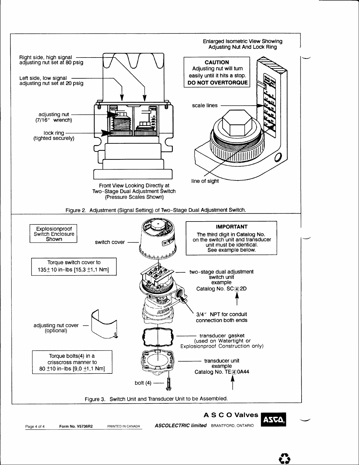
side, high signal
Right
adjusting
Left side, low signal
adjusting nut set at 20
nut set at
adjusting nut
(7116"
wrench)
lock ring
(tighted
securely)
80
psig
psig
Enlarged
Adjusting
CAUTION
Adjusting nut
until it hits a stop.
easily
NOT
DO
OVERTORQUE
lsometric View
Nut And Lock
will turn
Showing
Ring
Two-Stage Dual Adjustment Switch
Explosionproof
Enclosure
Switch
Shown
Torque switch cover
135+ 10
in-lbs
[15,3
switch cover
to
+1,1
A
.dj,illflJ$,;ou.,
-
l--1
\-J
Torque bolts(4) in
crisscross manner
+10
80
in-lbs
[9,0
a
to
+1,1
Nm]
View Looking
Front
(Pressure
Nm]
Scales
Setting)
bolt
Directly at
Shown)
of Two-Stage Dual
-
1+;
IMPORTANT
dlgit in
thlrd
The
the switch
on
unil must
example
See
two-stage
dual adjustment
switch
example
Catalog
314"
No.
NPT for
connection
transducer
(used
Explosionproof
Catalog
Watertight or
on
Construction
transducer
examPle
No.
catalog
unit and transducer
be identical.
No.
below.
unit
SC
B2D
A
T
I
conduit
both ends
gasket
only)
unit
TEE0A/+4
t
I
Page 4 of
4 Form
Figure
No. V5736R2
Switch
3.
PRINTED IN CANADA
Unit
Transducer Unit
and
ASCOLECTRIC
be
to
limited
Assembled.
ASCOValves
BRANTFoRD, oNrARto
t\}-
rt
 Loading...