

Page 1
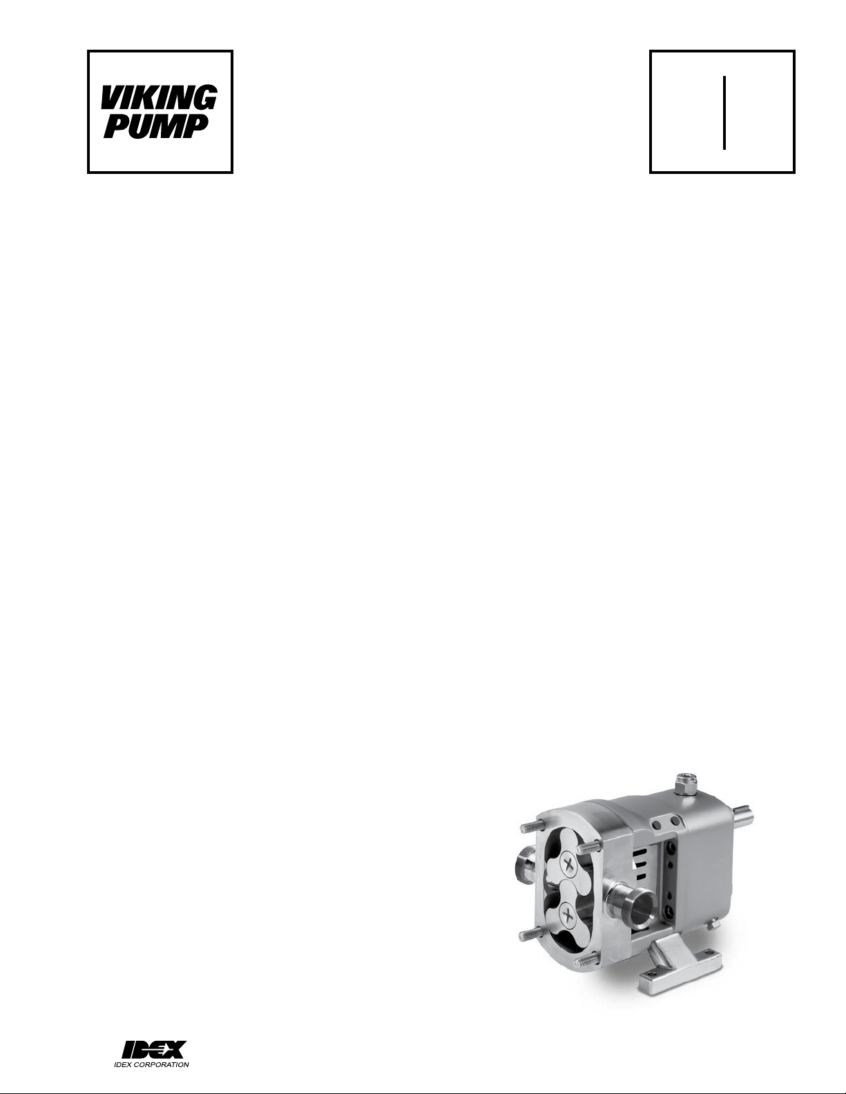
TECHNICAL SERVICE MANUAL
SECTION TSM 285
CLASSIC+ SERIES ROTARY LOBE PUMPS
MODELS CP10, CP20, CP30, CP40 & CP50
CONTENTS
1.0 Safety Information........................................................................ 2
Risk Assessment Relating to the Use of Viking Pump
1.1
Classic+ Rotary Lobe Pumps and Pump Units in
Potentially Explosive Atmospheres ..............................................
Introduction. .................................................................................3
2.0
2.1 General. .......................................................................................3
2.2 Viking Pump Distributors. ............................................................3
2.3 Receipts and Storage. ................................................................. 3
2.4 Cleaning....................................................................................... 3
2.5 Pump Model Designation............................................................. 4
2.5.1 AtexIdenticationPlate ...............................................................4
2.5.2 Equipment Groups & Categories .................................................4
2.6 Pump Model and Serial Number. ................................................. 4
Standard Pump Component Terms .............................................5
2.7
General. .......................................................................................5
3.0
3.1 Classic+ Pumping Principal. ........................................................5
3.2 Classic+ Range Operating Parameters. ......................................5
3.3 System Design............................................................................. 6
3.3.1 System Design and Installation. .................................................. 6
3.3.2 Installations with In-Line Cleaning Systems. ............................... 7
3.4 Start Up Procedure. .....................................................................8
3.5 Shutdown Procedure. .................................................................. 8
3.6 Routine Maintenance. .................................................................. 8
3.7 Heating and Cooling Jackets .......................................................8
3.8 Integral Pressure Relief Valves ..................................................10
3.8.1 Setting and Operating Spring Loaded Valves ............................ 10
3.8.2 Setting and Operating Air Loaded Integral
Pressure Relief Valves ...............................................................
Classic+ Disassembly and Assembly. .......................................12
4.0
4.1 CP10, CP20 & CP30 Pump - Disassembly and Assembly. .......12
4.1.1 CP10, CP20 & CP30 Head and Rotor Removal ........................ 12
4.1.2 CP10, CP20 & CP30 Casing Removal ...................................... 13
4.1.2.1 CP10, CP20 & CP30 Casing Removal - Single
Un-ushedMechanicalSealsandSingleO-RingSeals ............
4.1.2.2 CP10, CP20 & CP30 Casing Removal - Single Flushed
or Double Flushed Mechanical Seals. .......................................
4.1.3 CP10, CP20 & CP30 Gearbox Disassembly .............................14
4.1.4 CP10, CP20 & CP30 Gearbox Assembly .................................. 15
4.1.5 CP10, CP20 & CP30 Casing, Rotor and
Head Assembly ..........................................................................
4.2 CP40 Pumps - Disassembly and Assembly...............................17
4.2.1 CP40 Head and Rotor Removal ................................................17
4.2.2 CP40 Casing Removal .............................................................. 17
4.2.2.1 CP40CasingRemoval-SingleUn-ushedMechanical
Seals and O-Ring Seals ............................................................
4.2.2.2 CP40 Casing Removal - Single Flushed or Double
Flushed Mechanical Seals. ........................................................
4.2.3 CP40 Gearbox Disassembly...................................................... 18
4.2.4 CP40 Gearbox Assembly........................................................... 19
4.2.5 CP40 Casing, Rotor and Head Assembly .................................. 20
4.3 CP50 Pumps - Disassembly and Assembly...............................21
4.3.1 CP50 Head and Rotor Removal ................................................21
4.3.2 CP50 Casing Removal .............................................................. 21
4.3.2.1 CP50CasingRemoval-SingleUn-ushedMechanical
Seals and O-Ring Seals ............................................................
4.3.2.2 CP50 Casing Removal - Single Flushed and Double
Flushed Mechanical Seals .........................................................
4.3.3 CP50 Gearbox Disassembly...................................................... 22
4.3.4 CP50 Gearbox Assembly........................................................... 23
4.3.5 CP50 Casing, Rotor and Head Assembly .................................. 24
Classic+ Mechanical Seal Removal & Replacement. ................ 25
5.0
5.1 General Procedures for Installing Mechanical Seals. ................ 25
10
13
14
16
17
18
21
21
PAGE 1 OF 36
ISSUE A
5.2 CP10, CP20, CP30 & CP40 Mechanical Seals ......................... 25
5.2.1 CP10, CP20, CP30 & CP40
Single Mechanical Seal Removal ..............................................
5.2.2 CP10, CP20, CP30 & CP40
3
Single Mechanical Seal Replacement .......................................
5.2.3 CP10, CP20, CP30 & CP40
Single Flushed Mechanical Seal Removal ................................
5.2.4 CP10, CP20, CP30 & CP40
Single Flushed Mechanical Seal Replacement .........................
5.2.5 CP10 Double Flushed Mechanical Seal Removal ..................... 26
5.2.6 CP10 Double Flushed Mechanical Seal Replacement .............. 27
5.2.7 CP20, CP30 & CP40
Double Flushed Mechanical Seal Removal ...............................
5.2.8 CP20, CP30 & CP40
Double Flushed Mechanical Seal Replacement ........................
5.3 CP50 Mechanical Seals............................................................. 28
5.3.1 CP50 Single Mechanical Seal Removal ....................................28
5.3.2 CP50 Single Mechanical Seal Replacement .............................28
5.3.3 CP50 Single Flushed Mechanical Seal Removal ...................... 28
5.3.4 CP50 Single Flushed Mechanical Seal Replacement ............... 28
5.3.5 CP50 Double Flushed Mechanical Seal Removal ..................... 29
5.3.6 CP50 Double Flushed Mechanical Seal Replacement .............. 29
Classic+ Single O-Ring Seals .................................................... 29
6.0
6.1 General Procedures for Fitting Single O-Ring Seals ................. 29
6.2 O-Ring Seals for CP10, CP20, CP30 & CP40 Pumps............... 29
6.2.1 CP10, CP20, CP30 & CP40 O-Ring Seal
Assembly and Removal .............................................................
6.3 O-Ring Seal for CP50 Pump...................................................... 30
6.3.1 CP50 O-Ring Seal Assembly and Removal............................... 30
Flushed Product Seals Auxiliary Services ................................. 30
7.0
7.1 Single Mechanical Seal (for Low-Pressure Quench or Flush) ... 30
7.2 Double Mechanical Seal (for High Pressure Flush) ................... 30
Specications............................................................................. 31
8.0
Clearance Chart......................................................................... 31
8.1
Fasteners and Torque Settings .................................................. 32
8.2
Lubricants .................................................................................. 33
8.3
Troubleshooting ......................................................................... 33
8.4
8.5 MaterialSpecications ...............................................................
Foundation Dimensions and Weights ........................................ 34
8.6
Typical Noise Emission Data - CP10, CP20 & CP30 Pumps .... 35
8.7
Typical Noise Emission Data - CP40 & CP50 Pumps ............... 35
8.8
Classic+ Series CP20 Pump
25
25
26
26
27
27
29
33
VIKING PUMP, INC. • A Unit of IDEX Corporation • Cedar Falls, IA 50613 USA
Page 2
1.0 SAFETY INFORMATION
INCORRECT INSTALLATION, OPERATION OR MAINTENANCE OF EQUIPMENT MAY CAUSE SEVERE
PERSONAL INJURY OR DEATH AND/OR EQUIPMENT DAMAGE AND MAY INVALIDATE THE WARRANTY.
This information must be read fully before beginning installation, operation or maintenance and must be
kept with the pump. All installation and maintenance must be undertaken by suitably trained or qualified
persons only.
Symbol
Legend :
Danger - Failure to follow the listed
precautionary measures identified by
this symbol may result in serious injury
!
or death.
WARNING
Warning - Safety instructions which
shall be considered for reasons of safe
operation of the pump or pump unit and/
or protection of the pump or pump unit
itself are marked by this symbol.
!
!
!
!
WARNING
!
!
WARNING
WARNING
WARNING
DO NOT OPERATE PUMP IF:
- The head is not installed correctly.
- Any guards are missing or incorrectly installed.
- The suction or discharge piping is not connected.
DO NOTplace ngers,etc. intothepumping chamber
or its connection ports or into any part of the gearbox if
there is ANY possibility of the pump shafts being rotated.
Severe injury will occur.
DO NOT exceed the pumps rated pressure, speed, and
temperature, or change the system/duty parameters
from those for which the pump was originally supplied,
withoutconrmingitssuitabilityforthenewduty.Running
the pump outside of its operation envelope can cause
mechanical contact, excessive heat and can represent a
serious risk to health and safety.
Installation and operation of the pump must always
comply with health and safety regulations.
A device must be incorporated into the pump, system,
or drive to prevent the pump exceeding its stated duty
pressure. It must be suitable for both directions of pump
rotation where applicable. Do not allow pump to operate
with a closed/blocked discharge unless a pressure
relief device is incorporated. If an integral relief valve is
incorporated into the pump, do not allow re-circulation
through the relief valve for extended periods (refer to
section 3.8).
The mounting of the pump or pump unit should be solid
and stable. Pump orientation must be considered in
relation to drainage/cavity ventilation requirements.
Once mounted, shaft drive elements must be checked for
correct alignment. Rotate pump shaft by at least one full
revolution to ensure smoothness of operation. Incorrect
alignment will produce excessive loading and will create
high temperatures and increased noise emissions. It
may also be necessary to earth the pump head to avoid
the build up of a potential charge difference that could
cause a spark.
The installation must allow safe routine maintenance and
inspection (to replenish lubricants, check for leakage,
monitor pressures, etc) and provide adequate ventilation
necessary to prevent overheating.
Fill all gearboxes with the recommended grades and
quantities of lubricant (refer to section 3.4 and 8.3).
Beware ofover/underlling the gearbox as this could
cause the pump to overheat and mechanical damage
to occur.
Before operating the pump, be sure that it and all parts
of the system to which it is connected are clean and
free from debris and that all valves in the suction and
discharge pipelines are fully opened. Ensure that all
piping connecting to the pump is fully supported and
correctly aligned with its relevant connections. Misalignment and/or excess loads will cause severe pump
damage. This could result in unexpected mechanical
contact in the pump head and has the potential to be an
ignition source.
Be sure that pump rotation is correct for the desired
directionofow(refer to section 3.4).
WARNING
WARNING
!
!
!
!
!
!
WARNING
!
DO NOT install the pump into a system where it will run
dry (i.e. without a supply of pumped media) unless it is
equippedwithaushedshaftsealarrangementcomplete
withafullyoperationalushingsystem.Mechanicalseals
requirea thin uid lmtolubricate thesealfaces. Dry
running can cause excessive heat and seal failure.
Pressure gauges/sensors are recommended, next to
the pump suction and discharge connections to monitor
pressures.
Caution must be taken when lifting the pump. Suitable
lifting devices should be used as appropriate. Lifting eyes
installed on the pump must only be used to lift the pump,
not pump with drive and/or base plate. If pump is base
plate mounted, the base plate must be used for all lifting
purposes. If slings are used for lifting, they must be safely
and securely attached. For weights of bare shaft pumps,
refer to section 8.6.
DO NOT attempt any maintenance or disassembly of the
pump or pump unitwithoutrstensuringthat:
- The pump is fully isolated from the power source
(electric, hydraulic, pneumatic).
- The pumping chamber, pneumatic relief valve and
any shaft seal support system are depressurized and
purged.
- Any temperature control devices (jackets,
etc.) are fully isolated, that they are depressurized and
purged, and components are allowed to reach a safe
handling temperature.
DO NOT attempt to dismantle a pressure relief valve,
which has not had the spring pressure relieved, is still
connected to a pressurized gas/air supply or is mounted
on a pump that is operating. Serious personal injury or
death and/or pump damage may occur.
DO NOT loosen or undo the head, any connections to the
pump, shaft seal housings, temperature control devices,
or other components, until sure that such action will not
allow the unsafe escape of any pressurized media.
Pumps and/or drives can produce sound power levels
exceeding 85dB (A) under certain operating conditions.
When necessary, personal protection against noise must
be taken. Typical noise emission data can be found in
sections 8.7 and 8.8.
Avoid any contact with hot parts of pumps and/or drives
that may cause injury. Certain operating conditions,
temperature control devices (jackets, heat-tracing, etc.),
bad installation, or poor maintenance can all promote
high temperatures on pumps and/or drives.
When cleaning, either manually or by an in-line cleaning
method, the operator must ensure that a suitable
procedure is used in accordance with the system
requirements. During a in-line cleaning cycle, a pump
differential pressure of between 2 and 3 bar (30 and 45
psi) is recommended to ensure suitable velocities are
reached within the pump head. The exterior of the pump
should be cleaned periodically.
Surface temperature of pump is also dependent on the
temperature of pumped medium.
heat-tracing,
SECTION TSM 285 ISSUE A PAGE 2 OF 36
Page 3
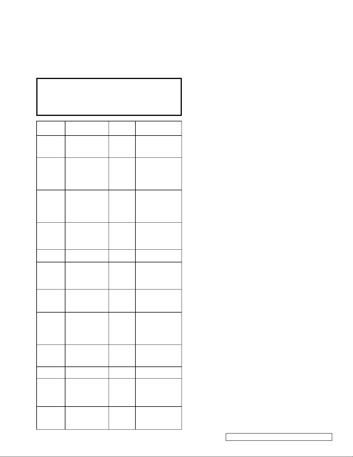
1.1 RISK ASSESSMENT RELATING
TO THE USE OF VIKING PUMP
CLASSIC+ ROTARY LOBE
PUMPS AND PUMP UNITS IN
POTENTIALLY EXPLOSIVE
ATMOSPHERES
NOTE
For a feature to be suitable for an application, the
feature must be t for its designated purpose and also
suitable for the environment where it is to be installed.
Source
of Hazards
Unvented
Cavities
Casing /
Rotors /
Head
Pump
External
Surfaces
Cover
O-Ring
Pump
Casing / Cover
Shaft Seals
Auxiliary
System for
Shaft
Sealing
Rotation
Direction
Test
Closed
Valve
Condition
Shaft
Mechanical
Shaft
Coupling
(Torque
Protection)
Mechanical
Shaft
Coupling
(Standard)
Potential
Hazards
Build up of explosive gas
Unintended mechanical
contact
Excess temperature.
Electrostatic charging
Pump liquid leakage.
Build up of explosive gas
Pump liquid leakage.
Build up of explosive gas
Excessive temperature.
Unintended mechanical
contact. Leakage.
up of explosive gas
Pump liquid leakage.
Build up of explosive gas
Excess Temperature
Excess Temperature.
Excess Pressure.
Mechanical Contact
Random induced current
Temperature from
friction. Sparks from
break up of shear pins.
Electrostatic charging
Break up of spider.
Unintended
mechanical contact.
Electrostatic charging
Build
Frequency
of Hazards
Very Rare
Rare
Rare
Very Rare
Very Rare
Rare
Rare
Very Rare
Rare
Very Rare
Rare
Rare
Recommended
Measures
Ensure that pump is totally
lled. Consider mounting
ports vertically.
See Chapter 1.0
Ensure that operating
pressures are not
exceeded. Ensure that
sufcient NPSH to prevent
cavitation. See Chapter
1.0 / 3.3.1 Service Plan
User must ensure
temperature limits. Do not
overll gearboxes with
lubricant. Provide a ground
contact for pump. See
Chapter 1.0 / Service plan
Check selection of
elastomers are suitable for
application. Ensure cover
retaining nuts are tight.
Service plan
Stainless Steel.
Corrosion Resistant
Selection of seal system
must be suitable for
application. See Chapter
5.0. Service plan. Seals
must never run dry
Selection of auxiliary seal
system must be suitable
for application. Seals must
never run dry
If ushed seals are
installed, ensure that
ush is applied to seal
assemblies. Only allow
pump to run for minimum
period - just a few seconds
Can cause excessive
pressure, heat and
mechanical contact.
See Chapter 1.0
Provide a ground contact
for pump. See Chapter 1.0
Coupling selection must
suit application.
See Chapter 1.0
Coupling selection must
suit application. Service
plan. See Chapter 1.0
2.0 INTRODUCTION
2.1 GENERAL
Classic+ rotary lobe pumps are manufactured by Johnson
Pump (UK) Ltd. a subsidiary of Viking Pump Inc., Cedar Falls,
USA, (a unit of the IDEX Corporation).
This manual includes all the necessary information for the
Classic+ and should be read prior to beginning installation,
operation, or maintenance.
Should you require any additional information regarding
the Classic+ contact Viking Pump or their local authorized
distributor, refer to section 2.2.
When asking for assistance please provide the pump model
and serial number. This information can be obtained from the
pump nameplate which is located on the side of the pump
gearbox cover, refer to section 2.6.
Should the nameplate be unreadable or missing, the serial
number is also stamped on either side of the casing refer to
section 2.6.
If the system or product characteristics are to be changed from
the original application for which the pump was selected, Viking
Pump or their authorized distributor should be consulted to
ensure the pump is suitable for the new application.
2.2 VIKING PUMP DISTRIBUTORS
Viking Pump distributes its products internationally via a network
of authorized distributors. Throughout this manual where
reference is made to Viking Pump, service and assistance will
also be provided by any Viking Pump authorized distributor for
Classic+.
2.3 RECEIPTS AND STORAGE
Upon receipt of the pump, immediately examine it for any signs
of visible damage. If any damage is noted, contact Viking
Pump or your Viking Pump distributor and clearly mark upon
the carriers’ paperwork that the goods have been received in a
damaged condition, with a brief description of damage.
If the pump is not required for immediate installation then it
should be stored in a clean, dry environment. It is recommended
that storage temperature should be between –10° and 40°C
(14°F and 105°F).
Further to the above, if the pump is not intended for installation
or use within 18 months or more then refer to Viking Pump,
or the Viking Pump authorized distributor for storage
recommendations.
2.4 CLEANING
The Classic+ pump series is suitable for both manual cleaning
and in-line cleaning, refer to section 3.3.2.
It is recommended that the exterior of the pump be cleaned
periodically with a non-aggressive, non-abrasive cleaning
solution.
SECTION TSM 285 ISSUE A PAGE 3 OF 36
Page 4
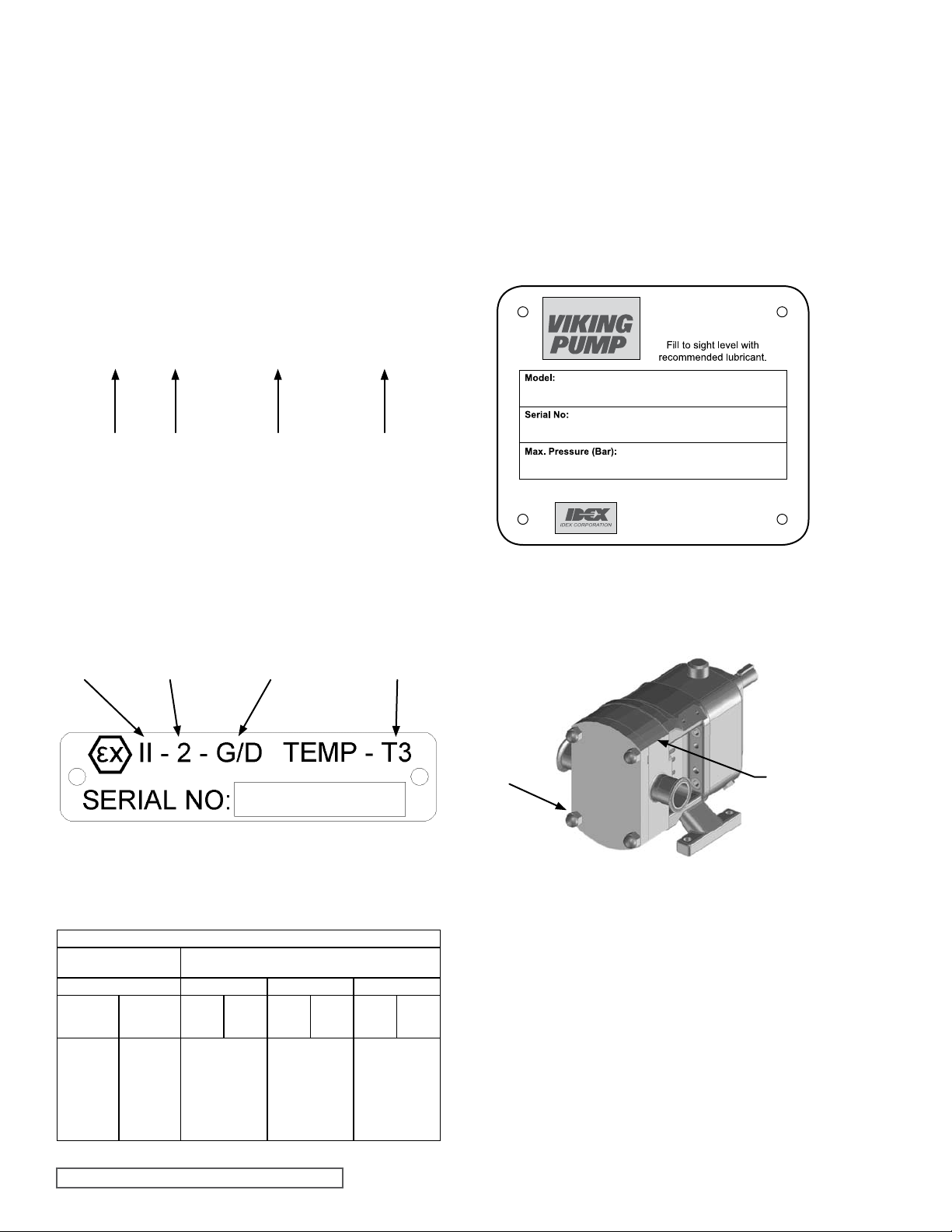
2.5 PUMP MODEL DESIGNATION
The designations of pump models in the Classic+ range are
asfollows:
CP10S CP20S CP30S CP40S
CP50S
CP10M CP20L CP30L CP40L CP50L
CP10L
This information, together with the pump serial number, should
be provided when requesting additional information on the
pump or when ordering spare parts. The pump serial number
is stamped on the pump nameplate and the casing, (refer to
section 2.6, Figures 2 and 3).
For the maximum operating pressures, temperatures and
speeds refer to section 3.2, Figure 6.
CP 30 / 0069 / 12
2.6 PUMP MODEL AND SERIAL
NUMBER
Should you require any information regarding your Classic+
rotary lobe pump contact Viking Pump or your Viking Pump
distributor, providing the pump model and serial number as
statedonthepumpnameplate,seeFigure2,whichisxedto
the pump gearbox cover.
Should this be damaged or missing, the pump serial number
is also stamped on opposite corners of the casing, (see
Figure 3).
Pump
Range
Model
Size
Displacement
(Ltrs/Rev)
Max Pressure
(Bar)
Figure 1
CP Designated Models Only
2.5.1 ATEX IDENTIFICATION PLATE
Unit is suitable
for environments
Temperature
Class
Group II Category 2
containing dust
or gas
2.5.2 EQUIPMENT GROUPS
& CATEGORIES
Equipment-groups (Annex I of the EC-Directive 94/9/EC)
Group I
(mines, mine gas & dust)
Category M Category 1 Category 2 Category 3
1 2
for equipment
providing a
very high level
of protection
when
endangered by
an explosive
atmosphere
for equipment
providing a
high level of
protection when
likely to
be endangered
by an explosive
atmosphere
(gas)
(Zone 0)
for equipment providing
a very high level of
protection when used
in areas where an
explosive atmosphere
is very likely to occur
(other explosive atmospheres gas/dust)
G
D
(dust)
(Zone 20)
Group II
G
(gas)
(Zone 1)
for equipment providing
a high level of
protection when used
in areas where an
explosive atmosphere
is likely to occur
D
(dust)
(Zone 21)
G
(gas)
(Zone 2)
for equipment providing
a normal level of
protection when used
in areas where an
explosive atmosphere
is less likely to occur
(dust)
(Zone 22)
VIKING P UMP, INC.
A Unit of IDE X Corporati on
CEDAR FAL LS, IOWA USA
Phone:( 319)266-17 41
Fax:(31 9)273-815 7
Figure 2
Nameplate
12345/A/67
Figure 3
Serial Number Position on Casing
D
SECTION TSM 285 ISSUE A PAGE 4 OF 36
Page 5
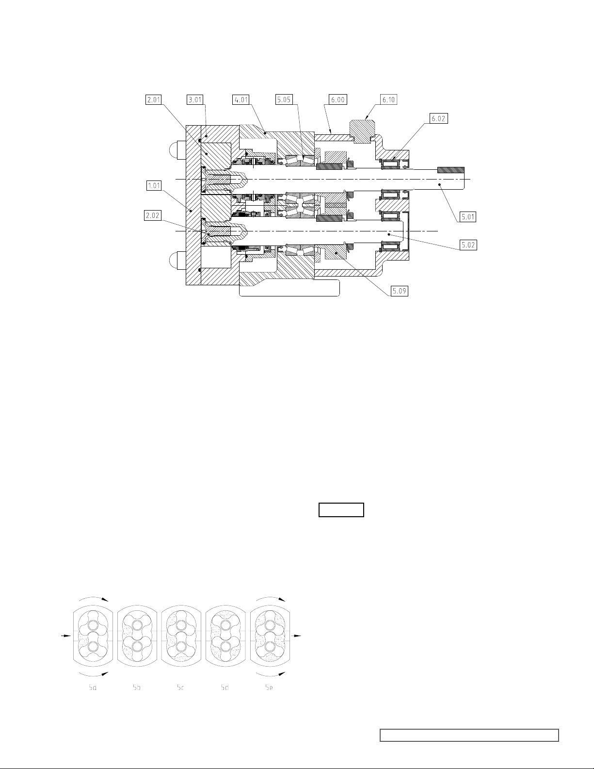
2.7 STANDARD PUMP
ROTORS
FRONT COVER
ROTOR
RETAINER
ROTORCASE
BEARING
HOUSING
FRONT
BEARINGS
GEARBOX
COVER
BREATHER
/FILLER CAP
REAR
BEARINGS
DRIVE
SHAFT
DRIVEN
SHAFT
TIMING
GEARS
COMPONENT TERMS
Figure 4
Pump Component Terms
3.0 GENERAL
3.1 CLASSIC+ PUMPING PRINCIPAL
The pumping action of the rotary lobe pump principle is
generated by the contra rotation of two pumping elements
(rotors) within a chamber (casing) - see Figure 5. The rotors are
located on shafts, which in turn are mounted within an external
gearbox and supported by the bearings; the timing gears are
also located on the shafts. The timing gears transfer the energy
from the drive shaft to the driven shaft, synchronizing the rotors
such that they rotate without contact with each other.
As the rotors pass the suction port, see Figure 5a, the cavity
generated increases creating a pressure decrease, which
inducesthepumpedmediumtoowintothecasing.
The pumped medium is carried around the casing by the rotors;
see Figure 5b and 5c, to the discharge side of the pump, Figure
5d. Here the cavity decreases and the pumped medium is
discharged from the casing, Figure 5e.
For pump component terms, see Figure 4.
3.2 CLASSIC+ RANGE OPERATING
PARAMETERS
The maximum pressure and speed operating parameters are
given in Figure 6. In practice these may be limited due to the
nature of the product to be pumped and/or design of the system
in which the pump is to be installed. Consult Viking Pump or
your Viking Pump distributor for assistance.
The operating temperature limit of the pump is determined
by the rotor clearance. For the CP10, CP20, CP30 and CP40
series pumps there are three rotor clearance bands (class A,
B and C), and two (class B and D) for the CP50 series pumps.
WARNING
The pump should not be subjected to sudden temperature
changes to avoid the risk of damage from sudden expansion/
contraction of components. Care should be taken when
selecting pumps for handling liquids containing abrasive
particles as these may cause wear of pump head components.
For advice or assistance contact Viking Pump or your Viking
Pump distributor.
If the system or product characteristics are to
be changed from the original application for
which the pump was selected, Viking Pump or
their authorized distributor should be consulted
to ensure the pump is suitable for the new
application.
Figure 5
Rotary Lobe Pumping Principle
SECTION TSM 285 ISSUE A PAGE 5 OF 36
Page 6
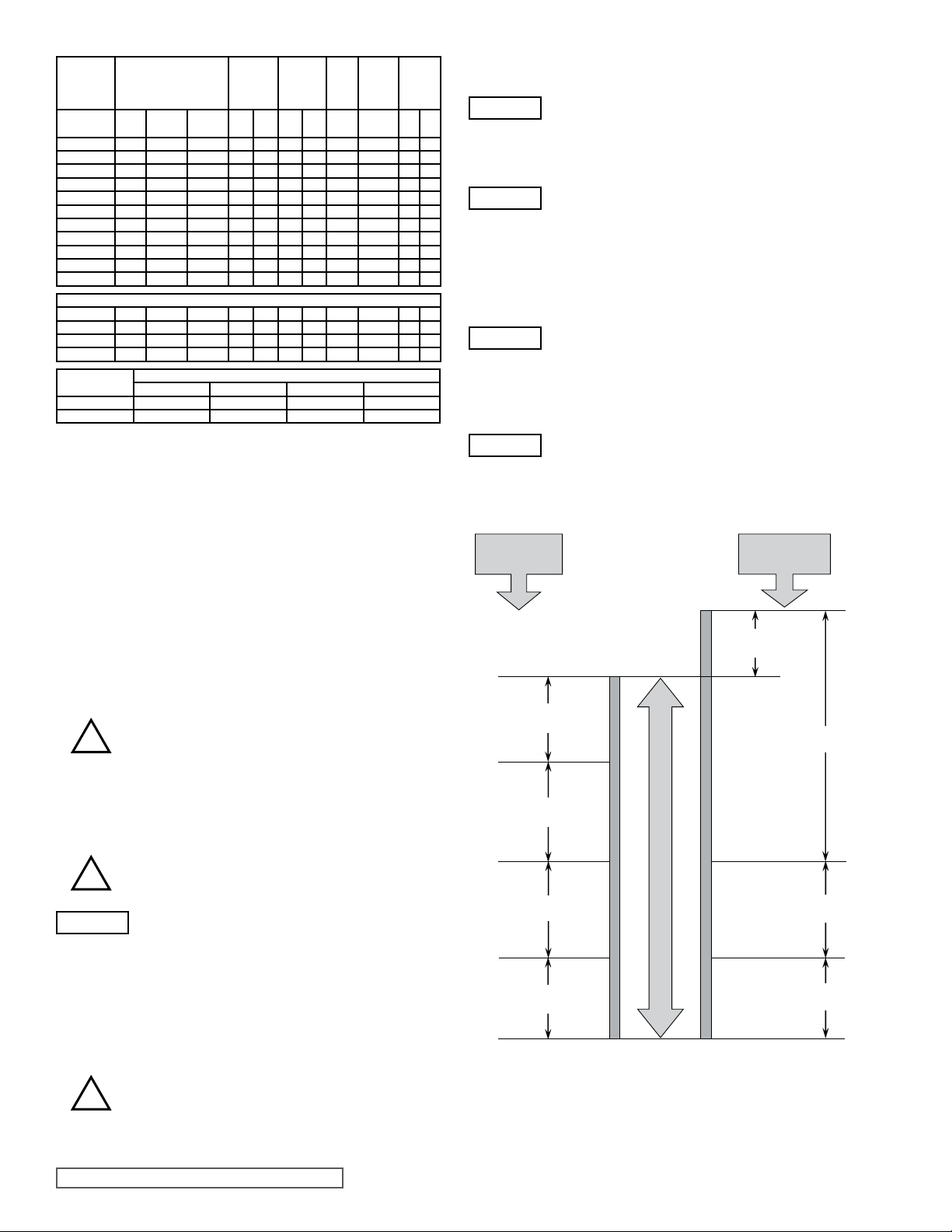
Pump Range Theoretical Displacement
10.0 Meters (32.8 Feet) Water Column
Suction Lift
Or Vacuum
Atmospheric
Pressure
Suction
Head
NPSH
Available
Suction Line
Friction Loss
Vapour
Pressure
NPSH
Available
Suction Line
Friction Loss
Vapour
Pressure
For Suction Lift
Or Vacuum
Conditions.
For Conditions
With Positive
Suction Head.
Atmospheric
Vacuum
Imp.gal
ltr/rev
CP10S 0.046 1.01 1.22 25 1 12 175 1400 1000 8.5 120
CP10M 0.083 1.83 2.19 38 1.5 8 120 1400 1000 5.5 75
CP10L 0.111 2.44 2.93 38 1.5 5 70 1400 1000 3.5 50
CP20S 0.202 4.44 5.34 38 1.5 12 175 1000 750 8.5 120
CP20L 0.313 6.89 8.27 50 2 7 100 1000 750 5.0 70
CP30S 0.694 15.27 18.34 50 2 12 175 750 550 8.5 120
CP30L 1.125 24.75 29.72 76 3 7 100 750 550 5.0 70
CP40S 1.800 39.60 47.56 76 3 12 175 700 520 8.5 120
CP40L 2.500 55.00 66.05 101 4 7 100 700 520 5.0 70
CP50S 3.514 77.31 92.84 101 4 12 175 650 420 8.5 120
CP50L 5.250 115.50 64.20 152 6 8 115 600 420 5.5 75
CP20/CP30 High Efciency Operating Parameters.
CP20S 0.202 4.44 5.34 38 1.5 7 100 1000 750 5.0 70
CP20L 0.313 6.89 8.27 50 2 4 55 1000 750 3.0 40
CP30S 0.694 15.27 18.34 50 2 7 100 750 520 5.0 70
CP30L 1.125 24.75 29.72 76 3 4 55 750 520 3.0 40
Classic+ Series
CP10, 20, 30, 40 70 100 150 N/A
CP50 N/A 100 N/A 180
/100 rev
Class A Class B Class C Class D
Nominal
Connection
Size
US gal
mm in. bar psi
/100 rev
Operating Temperature Limit (°C)
Max
Differential
Pressure
Max.
Speed
rev/
min
Max
Speed @
Max Diff.
Pressure
rev/min bar psi
Figure 6
Operating Parameters
3.3 SYSTEM DESIGN
Max Diff.
Pressure
@ Max
Speed
WARNING
WARNING
WARNING
WARNING
- Incorporation of a torque-limiting device in the
drive system.
It is recommended that all piping and associated
equipment from the tank to the discharge point
is thoroughly cleaned before installation of the
pump to avoid the possibility of debris entering
the pump and causing damage.
Pressure gauges should be installed adjacent to
the pump suction and discharge connections such
that system pressures can be monitored. These
gauges will provide a clear indication of changes
in operating conditions and where a relief valve
is incorporated in the system, will be necessary
for setting and checking the functioning of the
valve.
It is imperative that the suction condition at the
pump inlet meets the Net Positive Suction Head
required (NPSHr) by the pump. Failure to observe
this could cause cavitation, resulting in noisy
operation,reductioninowrateandmechanical
damage to the pump and associated equipment.
The Net Positive Suction Head available
(NPSHa) from the system must always exceed
the Net Positive Suction Head required (NPSHr)
by the pump.
3.3.1 SYSTEM DESIGN AND
INSTALLATION
When incorporating any pump into a system it is considered
good practice to minimize piping runs and the number of pipe
ttings (tees, unions, bends etc.) and restrictions. Particular
care should be taken in designing the suction line, which
should be as short and straight as possible with a minimum of
pipettingstominimiserestrictingproductowto the pump.
The following should be considered at the design stage of any
system.
Be sure ample room is provided around the pump
!
!
WARNING
Valves should be provided adjacent to the pump suction and
discharge connections to allow the pump to be isolated from
the system for routine inspection and maintenance.
!
SECTION TSM 285 ISSUE A PAGE 6 OF 36
toallowfor:
- Access to the pump and drive for routine
inspection and maintenance, i.e. to remove
pump head and rotors.
- Ventilation of the drive to prevent over
heating.
The exterior of the pump unit may exceed 68°C
(154°F); Appropriate measures must be taken to
warn or protect operators.
The pump must not be used to support piping.
All piping to and from the pump unit must be
independently supported. Failure to observe
this may distort the pump head components
or assembly and cause serious consequential
damage to the pump.
Rotary lobe pumps are of the positive displacement
type and therefore an overload protection device
mustbeprovided.Thiscantaketheformof:
- An in-line pressure relief system, i.e. external
to the pump.
Figure 7
NPSH
Page 7
Observing the following general guidelines should ensure the
best possible suction condition is created.
- Suction piping is at least the same diameter
connections.
- The length of suction piping is kept to the
minimum.
- The minimum number of bends, tees and
restrictions are used.
- Calculations to determine system NPSHa are
the worst condition see below.
Should advice on pump or system NPSH characteristics be
required contact the factory or their authorized distributor.
When installing a pump complete with base plate, motor and
drive,thefollowingguidelinesmustbeobserved:
a) The preferred drive arrangement for any
is in-line direct coupled. If an alternative is required please
contact Viking Pump or your Viking Pump distributor.
b) Flexible couplings must always be
!
!
!
!
f) When using electric motor drives, ensure
supply is compatible with the drive and controls and that the
method of wiring is correct for the type of starting required
by the motor i.e. Direct On Line, or other similar method.
Ensure all components are correctly grounded.
incorporated and correctly aligned within
the limits recommended by the coupling
manufacturer. To check coupling alignment
rotate the shaft by at least one full revolution
and ensure that the shaft rotates smoothly.
Couplings of a non-flexible design must never
be used.
c) Couplings must always be enclosed in a
suitable guard to prevent contact with rotating
parts, which could result in personal injury.
Guards should be of suitable material, (see d)
and of sufciently rigid design to prevent
contact with rotating parts under normal
operating conditions.
d) Whenthepumpisinstalledinaammableor
explosive environment, or is used for handling
ammable or explosive materials, special
consideration must be given. Not only to the
safety aspects of the drive unit enclosure
but also to the materials used for both the
coupling and the guard to eliminate the risk of
explosion.
e) Base plates must be secured to a at level
surface such that distortion and misalignment
are avoided. Once base plates are fastened
in position the drive alignment must be rechecked, (see b).
as the pump
absolute
pipework
carried out for
rotary lobe pump
that the electrical
When installing a pump complete with base plate, motor and
drive,thefollowingguidelinesmustbeobserved:
a) The preferred drive arrangement for any
is in-line direct coupled. If an alternative is required please
contact Viking Pump or your Viking Pump distributor.
b) Flexible couplings must always be
!
!
!
!
f) When using electric motor drives, ensure
supply is compatible with the drive and controls and that the
method of wiring is correct for the type of starting required
by the motor i.e. Direct On Line, or other similar method.
Ensure all components are correctly grounded.
incorporated and correctly aligned within
the limits recommended by the coupling
manufacturer. To check coupling alignment
rotate the shaft by at least one full revolution
and ensure that the shaft rotates smoothly.
Couplings of a non-flexible design must never
be used.
c) Couplings must always be enclosed in a
suitable guard to prevent contact with rotating
parts, which could result in personal injury.
Guards should be of suitable material, (see d)
and of sufciently rigid design to prevent
contact with rotating parts under normal
operating conditions.
d) Whenthepumpisinstalledinaammableor
explosive environment, or is used for handling
ammable or explosive materials, special
consideration must be given. Not only to the
safety aspects of the drive unit enclosure
but also to the materials used for both the
coupling and the guard to eliminate the risk of
explosion.
e) Base plates must be secured to a at level
surface such that distortion and misalignment
are avoided. Once base plates are fastened
in position the drive alignment must be rechecked, (see b).
rotary lobe pump
that the electrical
3.3.2 Installations with
CIP SYSTEMS
The Classic+ pump range is designed to be effectively cleaned
by the CIP procedures recommended for in place cleaning of
process plant. It is recommended that a differential pressure
of 2 to 3 Bar (30 to 45 psi) be developed across the pump
headduringcleaninginordertodevelopthenecessaryuid
velocities required for thorough cleaning.
SECTION TSM 285 ISSUE A PAGE 7 OF 36
Page 8
3.4 Start Up Procedure
WARNING
WARNING
WARNING
WARNING
WARNING
WARNING
WARNING
- Before beginning operation, it is considered
to momentarily start/stop the pump to check the direction of
rotation and ensure that the pump is free of obstructions.
Once this has been carried out, begin operation keeping a
visual check on suction and discharge pressure gauges and
monitor the pump temperature and absorbed power where
possible.
- Check that all piping and associated equipment
are clean and free from debris and that all pipe
connections are secure and leak free.
- For pumps tted with ushed product seals
check all auxiliary services are in place
and connected and provide sufcient ow
and pressure for ushing purposes, refer to
section 7.0.
- Ensure lubrication is provided for both pump
and drive. The Classic+ is shipped without oil
as standard and should be lled to the level
of the oil sight glass - refer to section 8.3 for
pump oil capacities and grades.
- If an external relief valve is incorporated in the
system, check that it is set correctly. For start up
purposes, it is considered good practice to set
the relief valve lower than the system design
pressure. On completion of start up, the relief
valve should be reset to the required setting
for the application. The required setting should
never exceed the lower of either the pumps
maximum pressure rating or the system design
pressure. For setting integral relief valves refer
to sections 3.8.1 and 3.8.2.
- Be sure both suction and discharge valves are
fully opened and that pipe work is free from
all obstructions. The Classic+ is a positive
displacement type pump and should therefore
never be operated against a closed valve as this
would result in pressure overload, resulting in
damage to the pump and possibly the system.
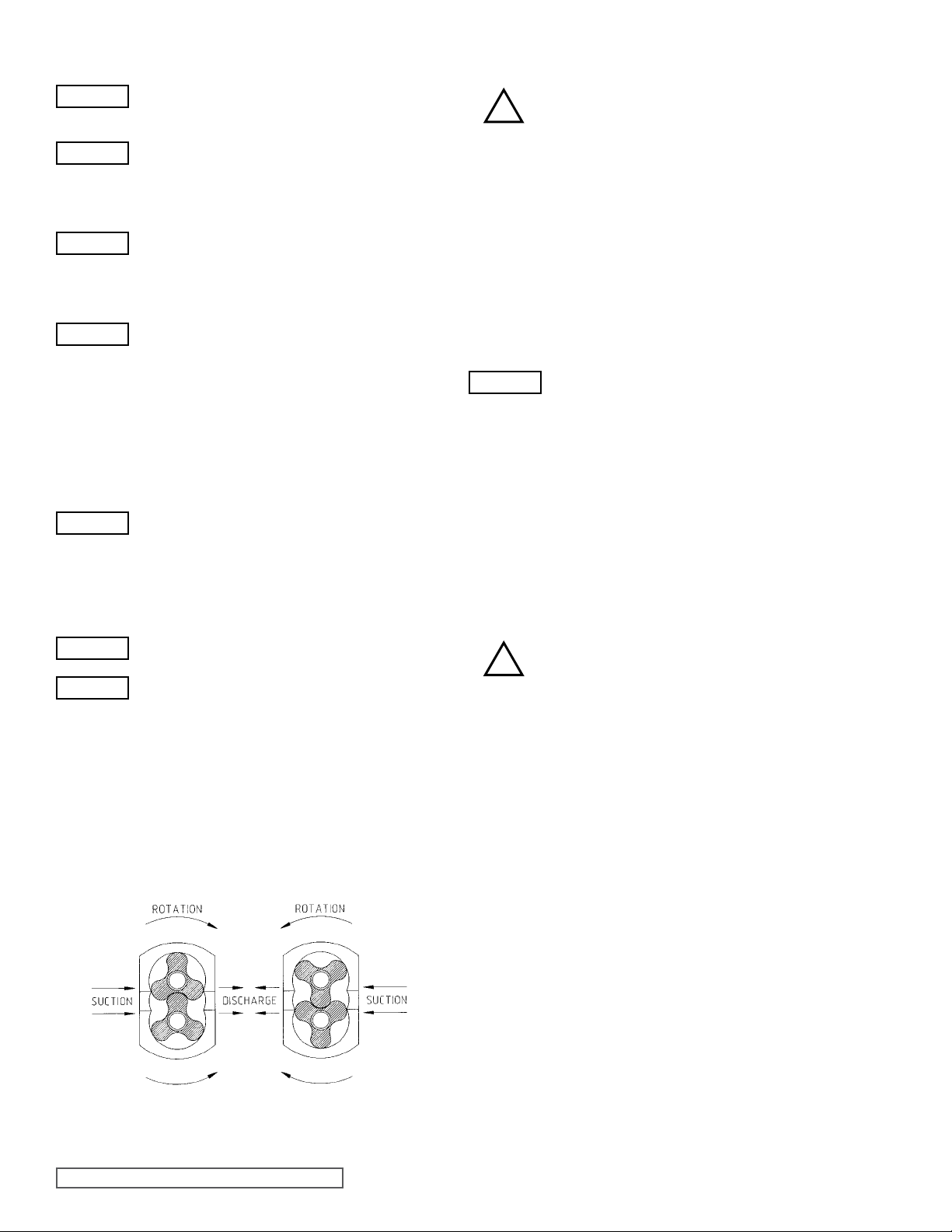
- Make sure that the drive shaft rotation is correct
forthedirectionofowrequired.SeeFigure8.
- Be sure product is available in the suction
vessel before starting the pump. This is very
important for pumps tted with un-ushed
product seals, as these sealing arrangements
must never be allowed to run dry.
good practice
3.5 SHUTDOWN PROCEDURE
When shutting the pump down, stop pump, close
!
both the suction and discharge valves and ensure
thatthenecessarysafetyprecautionsaretaken:
- The prime mover power source has been
isolated.
- If installed, pneumatically operated integral
relief valve has been depressurized.
- Flushed product seal auxiliary services have
been isolated and depressurized.
- Pump head and piping have been drained and
purged.
- Before undertaking any work on the pump refer
to sections 4, 5, 6 and 7.
3.6 ROUTINE MAINTENANCE
WARNING
- Change the oil every 12 months or 3000
whichever is the sooner.
- For lubricant capacities and grades refer to
- Check oil levels regularly.
operating hours,
section 8.3.
3.7 HEATING AND COOLING
JACKETS
SeeFigure9andFigure10.
The Classic+ can be supplied with a jacketed head and casing
for circulation of a heating/cooling media.
The jacketed head and casing ports are strategically positioned
such that the required thermal effect acts on the pumping
chamber.
The pressure rating of the Classic+ series jacketed
!
Heating/cooling of the pump head is used to maintain, rather
than increase/decrease the temperature of the pumped media
and should be used as part of a complete system where suction
and discharge lines and vessels are also heated/cooled.
Where heating/cooling devices are employed, the heating/
cooling media should be circulated 15-20 minutes prior to pump
start-up and should be allowed to continue for a similar period
of time after the pump has been shut down. Where an in-line
cleaning cycle is employed as part of the process, then the
heating/cooling media should continue to be circulated during
the cleaning cycle.
head and casing is 3 Bar (50 psi) and this should
not be exceeded without consulting Viking Pump
or your local Viking Pump distributor.
Figure 8
Rotation Against Suction and Discharge
SECTION TSM 285 ISSUE A PAGE 8 OF 36
Page 9
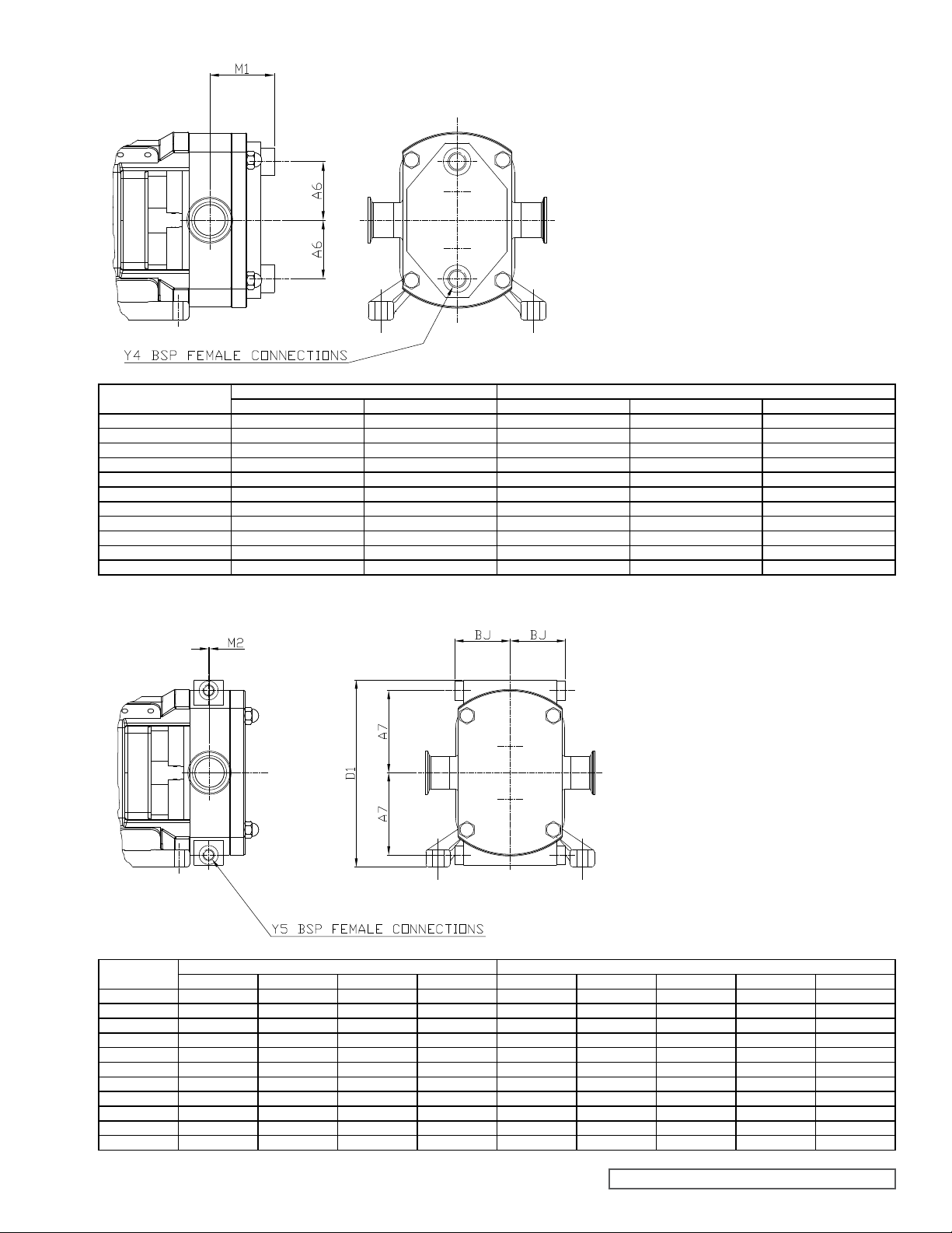
Figure 9
Dimensions of Jacketed Head
for Heating/Cooling
Model
CP10/0005/12 50.0 52.0 1.97 2.05 ¼”
CP10/0008/08 50.0 61.0 1.97 2.40 ¼”
CP10/0011/05 50.0 61.0 1.97 2.40 ¼”
CP20/0020/12 64.0 71.0 2.52 2.80 ½”
CP20/0031/07 64.0 81.0 2.52 3.19 ½”
CP30/0069/12 92.5 81.0 3.64 3.19 ½”
CP30/0113/07 92.5 96.0 3.64 3.78 ½”
CP40/0180/12 130.0 108.0 5.12 4.25 ½”
CP40/0250/07 130.0 123.0 5.12 4.84 ½”
CP50/0351/12 175.0 115.0 6.89 4.53 ½”
CP50/0525/08 175.0 138.0 6.89 5.43 ½”
A6 M1 A6 M1 Y4
Millimeters Inches
Figure 10
Dimensions of Jacketed Casing
for Heating/Cooling
Model
CP10/0005/12 70.0 56.0 156.0 3.0 2.76 2.20 6.14 0.12 ¼
CP10/0008/08 70.0 56.0 156.0 2.0 2.76 2.20 6.14 0.08 ¼
CP10/0011/05 70.0 56.0 156.0 7.5 2.76 2.20 6.14 0.30 ¼
CP20/0020/12 80.0 64.0 216.0 0.0 3.15 2.52 8.50 0.00 ¼
CP20/0031/07 80.0 64.0 216.0 1.0 3.15 2.52 8.50 0.04 ¼
CP30/0069/12 118.0 93.0 280.0 1.0 4.65 3.66 11.02 0.04 ½
CP30/0113/07 118.0 93.0 280.0 3.5 4.65 3.66 11.02 0.14 ½
CP40/0180/12 156.0 125.0 352.0 2.5 6.14 4.92 13.86 0.10 ½
CP40/0250/07 156.0 125.0 352.0 3.5 6.14 4.92 13.86 0.14 ½
CP50/0351/12 191.0 155.0 430.0 8.0 7.52 6.10 16.93 0.31 ½
CP50/0525/08 191.0 155.0 430.0 10.0 7.52 6.10 16.93 0.39 ½
A7 BJ D1 M2 A7 B J D1 M2 Y5
Millimeters Inches
SECTION TSM 285 ISSUE A PAGE9 OF 36
Page 10
3.8 INTEGRAL PRESSURE RELIEF
VALVES
See Figures 11, 12, 13 and 14.
The Classic+ models CP10, CP20, CP30 and CP40 can be
supplied with integral pressure relief valves. For the CP10,
CP20 and CP30 both spring and air loaded versions are
available. The function of the valves can be further enhanced
with the option of manual or airlift override, offering particular
benetswhere CIPorSIPproceduresareemployed.Valves
incorporating this option can be opened to regulate the ow
of the cleaning media through the pump chamber, thereby
avoiding the need for manual cleaning or external bypass.
Where the pump is mounted onto a portable base plate,
complete with motor and drive to be used as a mobile set, an
integral pressure relief valve should be installed.
TheClassic+integralpressurereliefvalvesavailableinclude:
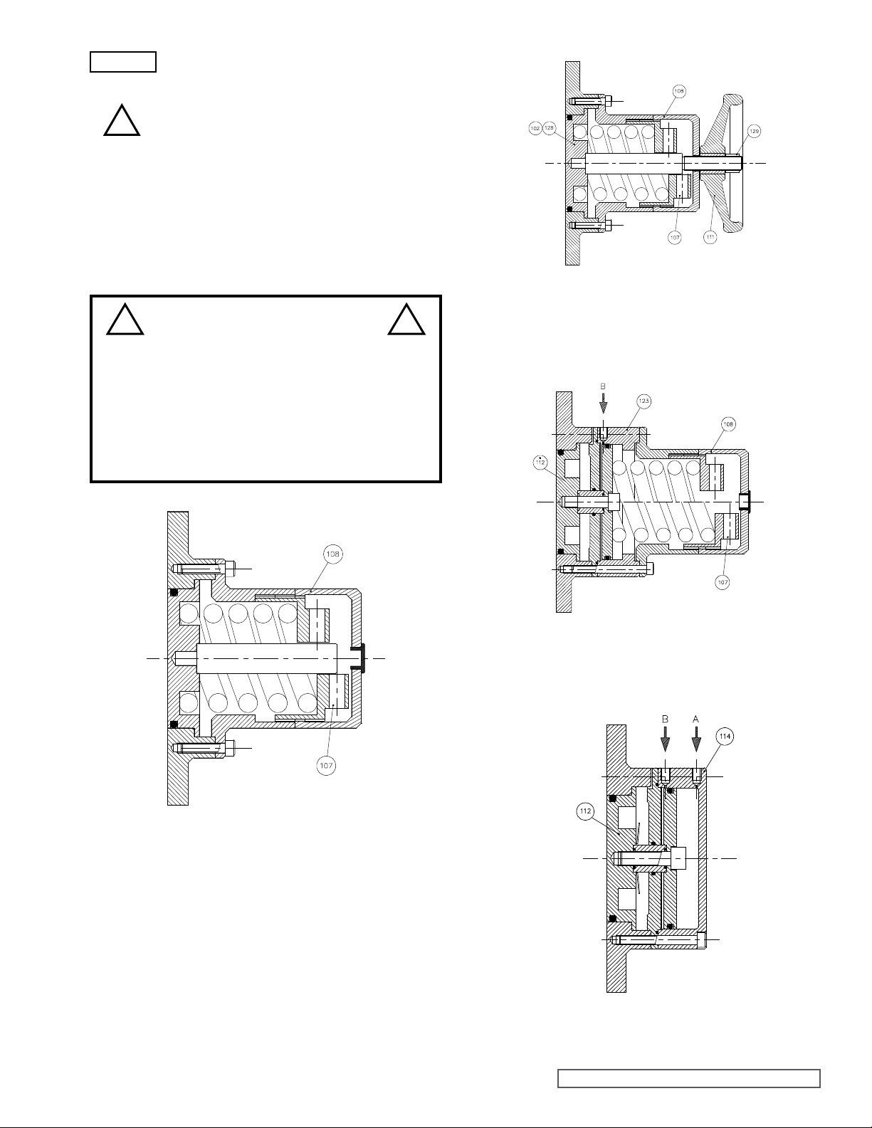
Spring Loaded - see Figure 11.
- Valve can be set to the required pressure relief setting.
Spring Loaded with Manual Lift - see Figure 12.
- Valve can be set to the required pressure relief setting.
Manual lift override can be used to open valve without
disturbing pressure relief setting.
Spring Loaded with Air Lift - see Figure 13.
- Valve can be set to the required pressure relief setting. Air
override, which operates on an air supply of up to 7 Bar (102
psi) depending on pressure relief setting, can be used to
open valve without disturbing pressure relief setting.
Air Loaded with Air Lift - see Figure 14.
- Valve, which operates on an air supply of up to 7 Bar
psi) regulated for required setting, can be set to the required
pressure relief setting. Airlift override, which operates on an
air supply of up to 7 Bar (102 psi) depending on pressure
relief setting, can be used to open valve without disturbing
pressure relief setting.
Air actuated relief valves can be operated remotely and interfaced with other elements of the system or process control.
WARNING
Ifthepumponwhichthevalveisttedistobeinstalledwithin
either a pressurised system or one incorporating a vessel under
vacuum then the application of the valve should be referred to
Viking Pump.
Integral pressure relief valves are normally used
to protect the pump from the effects of increases
in system pressure caused, for example, by a
restricted or closed discharge line. In response
to a pressure increase, the valve opens and
internally circulates the pumped media within the
pump chamber. When the valve opens, because
the volume of liquid circulating is relatively small,
the temperature of the liquid in the pump chamber
may rise if the pump continues to operate for
an extended period. In severe cases, this may
result in temperatures in excess of the pumps
operating limits, or vaporisation of the liquid, both
of which should be avoided. For these reasons
when the valve is activated the cause of the
system pressure increase should be eliminated
as continuous operation of the pump with the
valve open is not recommended and may cause
severe damage to the pump.
lift
(102
The selection, setting and application of integral relief valves is
inuencedbytheviscosityandnatureofthepumpedmedia,the
pumps operating speed and the required pressure relief setting
and mode of operation. For these reasons and to cover the
diverse range of products, the conditions under which they are
pumped and application demands, it is not practical to factoryset integral relief. Valves and the setting of the valves should
be carried out on site, under the proposed duty conditions for
which the pump and valve were selected.
For setting and operating Classic+ integral relief valves refer
to sections 3.8.1 and 3.8.2. Before beginning the relief valve
setting procedure the pump should be installed, refer to section
3.3.1, paragraph (vi), with a pressure gauge in the discharge
line adjacent to the pump discharge port.
3.8.1 SETTING AND OPERATING
SPRING LOADED VALVES
See Figures 11, 12 and 13.
- Remove cover (108). For integral relief valve with manual lift,
seeFigure12;rstremovenut(129)andhandwheel(111).
- Unscrew nut (107) using pry bar in holes
!
- Start pump. - refer to section 3.4.
- Screw in nut (107) using pry bar in holes provided until the
required pressure relief setting is reached.
WARNING
- Reinstall cover (108). For integral relief valve with manual
lift,seeFigure12;reinstallhandwheel(111)andnut(129).
- The relief valve is now set.
For Integral Relief Valve with Manual Lift - see Figure 12.
- To operate the manual lift, turn the hand wheel (111)
which will lift the valve head (102/128). To resume normal
relief valve operation, turn the hand wheel (111) counterclockwise.
For Integral Relief Valve with Air Lift - see Figure 13.
- To actuate the airlift, connect an air supply not exceeding
7 Bar (102 psi) to the cylinder (123), connection ‘B’, which
will lift the valve head (112). To resume normal relief valve
operation, exhaust the cylinder (123).
provided to relieve spring compression. For
integral relief valve with airlift, see Figure 13,
the air cylinder must be exhausted prior to
unscrewing the nut (107).
Note: Care should be taken not to exceed the
lower of either the pump’s maximum pressure
rating or the system design pressure.
clockwise,
3.8.2 SETTING AND OPERATING
AIR LOADED INTEGRAL
PRESSURE RELIEF VALVES
See Figure 14.
- Connect an air supply, not exceeding 7 Bar (102 psi), via
a regulating valve to the relief valve connection ‘A’ in the
cylinder (114). Do not turn on the air supply.
- Start the pump, refer to section 3.4.
- Using the regulating valve, gradually increase the air
pressure until required pressure relief setting is reached. The
air pressure must not exceed 7 Bar (102 psi).
- The relief valve is now set.
SECTION TSM 285 ISSUE A PAGE 10 OF 36
Page 11
WARNING
!
! !
Note: Care should be taken not to exceed the
lower of either the pump’s maximum pressure
rating or the system design pressure.
- To use the air lift system, the regulated air
supply must be routed through a change-over
valve in order to transfer air from the relief valve
load air chamber, connection ‘A’, to the lift air
chamber, connection ‘B’, while depressurizing
the load chamber and vice versa. The changeover valve will actuate the air lift which will lift
when the air supply is diverted to connection
‘B’, and will close, restoring normal relief valve
operation, when the air supply is diverted back
to connection ‘A’.
DANGER !
Under no circumstances should any
attempt be made to dismantle a pressure
relief valve which has not had the spring
pressure relieved, is still connected to a
pressurized air supply, or is mounted on a
pump that is operating. Serious personal
injury or pump damage may occur.
Figure 12
Spring Loaded Integral Pressure Relief Valve
with Manual Lift
CP10, CP20 and CP30
Figure 11
Spring Loaded Integral Pressure Relief Valve
CP10, CP20, CP30, CP40
Figure 13
Spring Loaded Integral Pressure Relief Valve with Air Lift
CP10, CP20 and CP30
Figure 14
Air Loaded Integral Pressure Relief Valve with Air Lift
CP10, CP20, CP30 and CP40
SECTION TSM 285 ISSUE A PAGE 11 OF 36
Page 12
4.0 CLASSIC+ DISASSEMBLY AND
ASSEMBLY
Before starting any work on the pump the
!
!
!
During disassembly or before assembly, all components should
beinspectedfort,wearanddamage.Ifwornordamagedthe
components should be replaced.
Thepositionofallpartsshouldbeidentiedastheyareremoved
to ensure they are reinstalled in the same position.
Lipseals and O-rings are incorporated within the gearbox
assembly to contain the lubricant for the bearings and timing
gears. Regular inspection and correct maintenance of these
items will ensure that the lubrication is sustained and the pump
maximum working life is achieved. To ensure this, it is extremely
important that care is taken when removing and replacing new
O-rings and lipseals. When removing and replacing lipseals
ensure that the location bore for the outside diameter and the
seat for the back of the lipseal is not damaged as this may
create a leak path for the lubricant.
When removing lipseals or O-rings care should be taken to
avoid cutting or tearing the sealing faces as they pass over
keyways, splines, threads or other potentially sharp or abrasive
edges. All lipseals and O-rings should be carefully examined
and if damaged in any way, be replaced.
All O-rings and sealing lips of lipseals should be lightly lubricated
with an appropriate lubricant (suitable for application) before
installing.
When installing lipseals do not allow the rear face to come into
contact with bearings or other rotating parts.
Prior to beginning assembly, ensure all parts are clean and free
from burrs or damage. Where a vice is to be used then this
should be installed with protective jaws to avoid damage to
components. Do not hammer or apply undue force to install or
position components.
WARNING
!
Under no circumstances should bearing cones or cups be
hammered into position.
recommended Shutdown Procedure should be
followed, refer to section 3.5.
While disassembling or assembling the pump
it is essential to ensure that the pump and/or
components are secured to provide adequate
stability.
Large pump components or sub-assemblies
should be installed using suitable devices. Use
threaded holes for the attachment of lifting eyes
where appropriate.
All fasteners are required to be tightened to the
required torque setting during assembly, refer to
section 8.2.
The preferred method of installing bearing cones
is that they are heated to approximately 125°C
(250°F) prior to installation. During this operation
protective gloves should be used. Once bearing
cones are installed in the correct position they
should be allowed to cool before proceeding
with assembly. As an alternative, bearing cones
may be pressed into position providing the
proper equipment is utilized and the necessary
procedures are used to prevent component
damage.
4.1 CP10, CP20 AND CP30 PUMP -
DISASSEMBLY AND ASSEMBLY
4.1.1 CP10, CP20 AND CP30 HEAD
AND ROTOR REMOVAL
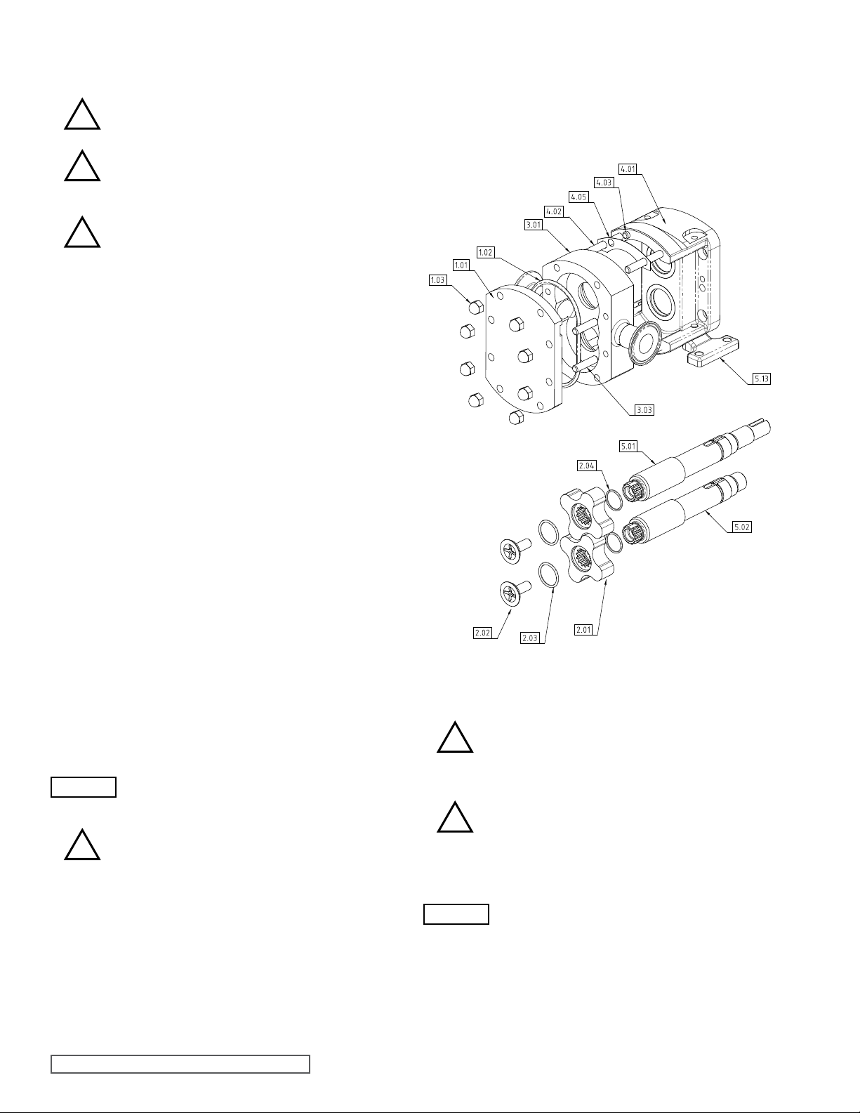
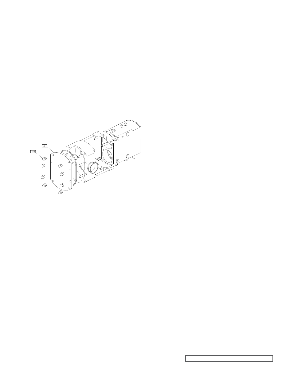
Figure 15
CP10 Exploded View of Casing and Rotor Assembly
- Follow recommended shutdown procedure.
!
- For CP10 Pump – refer to Figure 15.
- For CP20 Pump – refer to Figure 16.
!
- Remove dome nuts (1.03).
WARNING
- Failure to observe this will result in damage to the pump.
- Remove head (1.01) using lever slots where
the head O-ring (1.02) or optional gasket (not shown).
- Remove rotor retainers’ (2.02) with socket supplied (not
shown).
Refer to section 3.5.
- Gradually loosen head retaining dome
(1.03). Care should be taken as there may still
be residual product and pressure in the pump
head and as the dome nuts are loosened, this
will vent to atmosphere.
Note: CP10 Pump Only - Do not rotate shafts
at this stage as the casing is held in place by
the head retaining dome nuts (1.03).
necessary and
nuts
SECTION TSM 285 ISSUE A PAGE 12 OF 36
Page 13
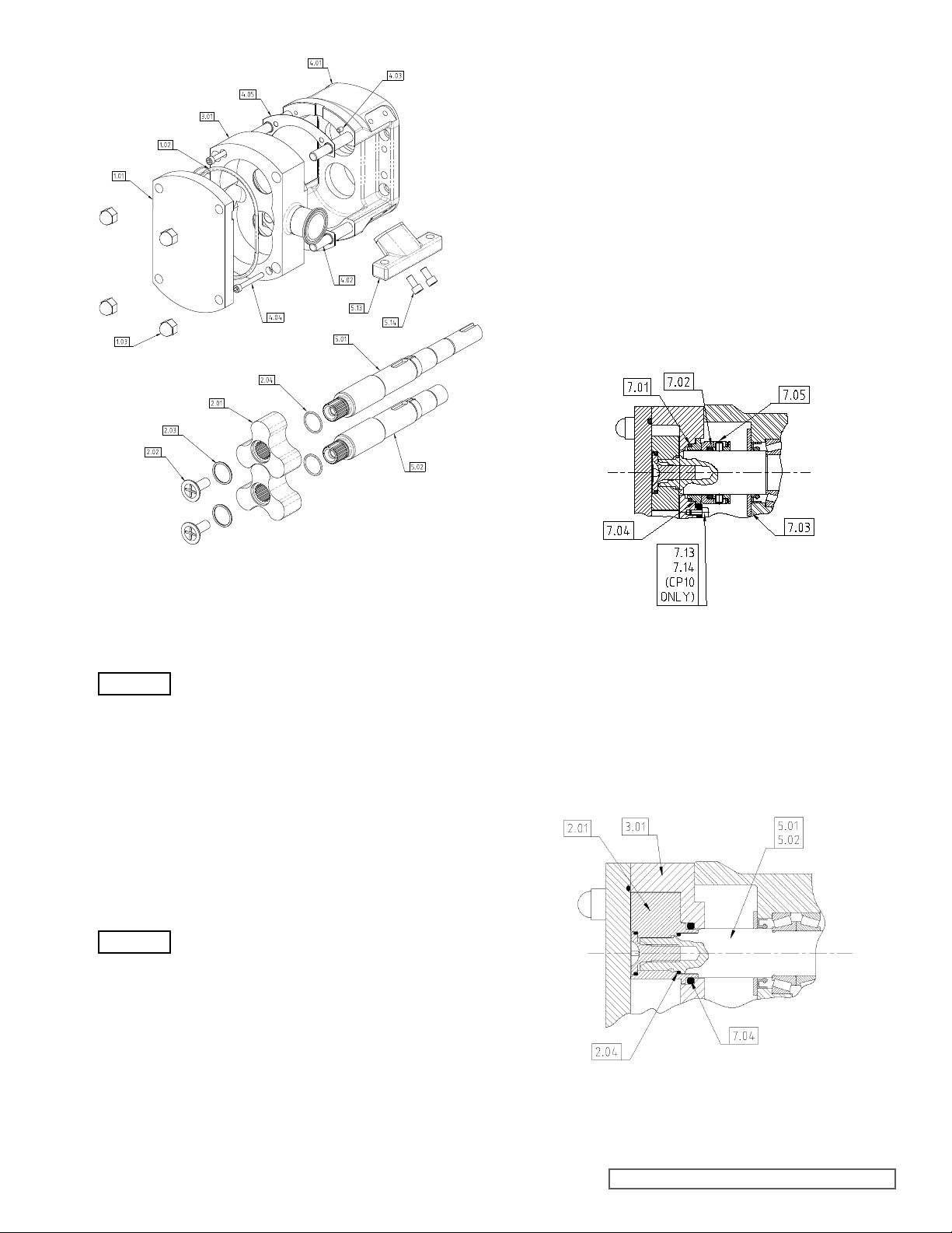
CP10 Pump Only
(After completing section 4.1.1)
- Slide casing (3.01) from bearing housing (4.01), noting
it is located on dowels (4.03), keep arch shims (4.05) in
appropriate sets if they are to be reused.
CP20 and CP30 Pump Only
(After completing section 4.1.1)
- Remove casing retention socket cap head screws (4.04)
with appropriate metric allen key (not supplied).
- Slide casing (3.01) from bearing housing (4.01), noting
it is located on dowels (4.03), keep arch shims (4.05) in
appropriate sets if they are to be reused.
Single Un-Flushed Mechanical Seal as shown in Figure 17.
- See section 5.2.1 for removal and section 5.2.2 for
replacement.
Figure 16
CP20/CP30 Exploded View of Casing
and Rotor Assembly
WARNING
- Remove retainer O-rings (2.03).
- Remove rotors (2.01) from shafts (5.01 and 5.02).
- Remove rotor O-rings (2.04) – Not fitted on O-ring seal
version of CP10.
Note: If the pump is tted with O-ring Seals (instead of
mechanical seals) then the O-ring seal will now be visible
– Chapter 6.0 for further information.
Note: The socket tool should always be
used, the use of other tools may damage the
retainer.
4.1.2 CP10, CP20 AND CP30
CASING REMOVAL
WARNING
Note: Ensure all pipe work is disconnected
before commencing casing removal.
4.1.2.1 CP10, CP20 AND CP30
CASING REMOVAL
FOR PUMPS FITTED WITH
SINGLE UN-FLUSHED
MECHANICAL SEALS AND
SINGLE O-RING SEALS
Figure 17
Single Un-Flushed Mechanical Seal
Single O-ring Seal as shown in Figure 18 – see section 6.2.1
for removal and replacement.
- Remove rotor (2.01).
- Remove O-ring seal (7.04) from casing (3.01).
Figure 18
O-ring Seal
SECTION TSM 285 ISSUE A PAGE 13 OF 36
Page 14
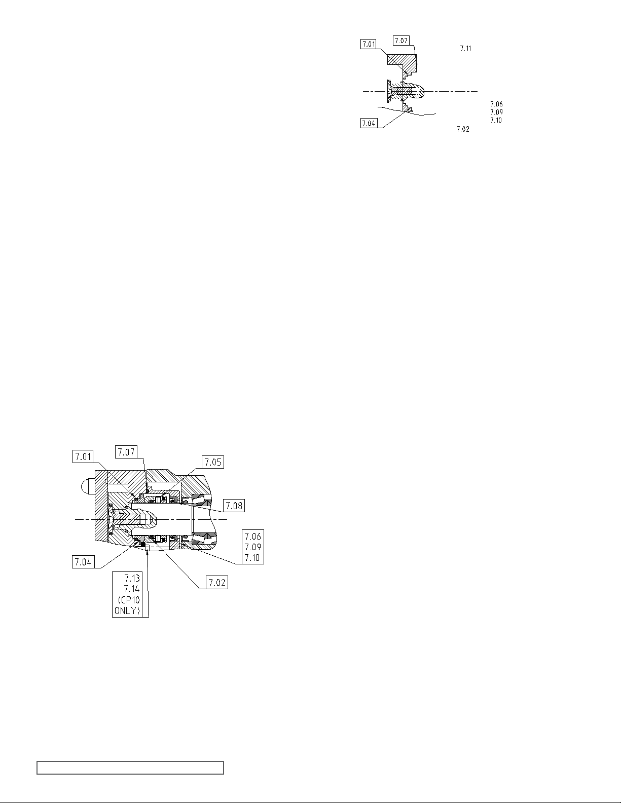
4.1.2.2 CP10, CP20 AND CP30
CASING REMOVAL
FOR PUMPS FITTED WITH
SINGLE FLUSHED OR
DOUBLE FLUSHED
MECHANICAL SEALS.
Prior to removal of casing (3.01) for CP10, CP20 and CP30,
remove seal housing screws (7.10) and separate housing
(7.06)fromcasing(3.01)notingitislocatedondowels(7.09).
CP10 Pump Only
(After completing section 4.1.1) - see Figure 15.
- Slide casing (3.01) from bearing housing (4.01), noting
it is located on dowels (4.03), keep arch shims (4.05) in
appropriate sets if they are to be reused.
CP20 and CP30 Only
(After completing section 4.1.1) - see Figure 16.
- Remove casing retention socket cap head screws (4.04)
with appropriate metric allen key (not supplied).
- Slide casing (3.01) from bearing housing (4.01), noting
it is located on dowels (4.03), keep arch shims (4.05) in
appropriate sets if they are to be reused.
SingleFlushedMechanicalSealasshowninFigure19.
- See section 5.2.3 for removal and section 5.2.4 for
replacement.
Double Flushed Mechanical Seal as shown in Figure 20 and
Figure 21.
- CP10 Pump - see section 5.2.5 for removal and 5.2.6 for
replacement.
- CP20 and CP30 Pumps – see section 5.2.7 for removal and
5.2.8 for replacement.
4.1.3 CP10, CP20 AND CP30
GEARBOX DISASSEMBLY
(After completing 4.1.1 or 4.1.2)
Figure 19
Single Flushed Mechanical Seal
SECTION TSM 285 ISSUE A PAGE 14 OF 36
Page 15
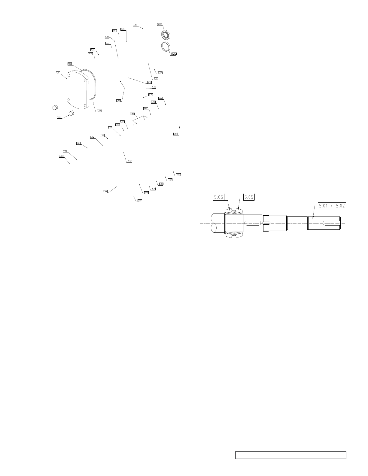
Figure 23
CP20 and CP30
Component Parts
- CP10 Pumps Only
(5.16), keep shims and spacers in sets and identify position.
- CP30 Pumps Only
identify position.
- Remove screws (5.07) and retainers (5.06) from bearing
housing (4.01).
- Remove shafts (5.01 and 5.02) from bearing housing (4.01)
Shafts (5.01 and 5.02) will be complete with bearings (5.05)
and shims (5.04), keep shims in sets and identify position.
- Remove oil seals (5.03) from bearing housing (4.01).
- Remove bearing cups (5.05) and any associated shims
(5.04) from bearing housing (4.01), keep bearing cups (5.05)
and shims (5.04) in sets and identify position.
- Remove bearing cones (5.05) from shafts (5.01 and 5.02).
- Remove shims (5.08) and spacers
- Remove shims (5.08) in sets and
4.1.4 CP10, CP20 AND CP30
GEARBOX ASSEMBLY
Refer to Figure 22 for CP10 or Figure 23 for CP20 and CP30.
- Install bearing cones (5.05) to shafts (5.01 and 5.02)
they locate against shaft shoulder. The cones are installed
as shown in Figure 24.
ensuring
Before starting disassembly of the gearbox remove product
seals; refer to section 5.0 for Mechanical Seals, or section 6.0
for O-ring seals.
The following procedure describes complete disassembly of
the gearbox.
- Refer to Figure 22 for CP10; Refer to Figure 33 for CP20
CP30.
- Remove guard (5.06).
- Remove drive key (6.12).
- Removeoildrainplug(6.09)andbreather(6.10),drain
suitable container and retain if later inspection is required.
- Remove screws (6.11) and separate gearbox cover (6.00)
from bearing housing (4.01). The gearbox cover (6.00) is
located on dowels (6.06)
Note: The bearing housing (4.01) is provided with two
jacking holes (tapped M8 on CP10; M10 on CP20; M12 on
CP30), which can be used to separate the gearbox cover
(6.00) from the bearing housing (4.01).
- Remove gasket (6.05) from gearbox cover (6.00) or bearing
housing (4.01) depending upon which part the gasket is
adhered to.
- Remove oil seal (6.03) and blanking cap (6.04) from gear
cover (6.00).
- Remove retaining rings (6.01) from gearbox cover (6.00)
press out bearing outer rings (6.02).
- Remove bearing inner ring (6.02) from shafts (5.01 and
- CP10 & CP20 Pumps Only
tab washers’ (5.11).
- CP30 Pumps Only
nuts (5.12).
- Removetiminggears(5.09)andgearkeys(5.10).
– Loosen locking screws from and lock
- Remove lock nuts (5.12) and
and
oil into
box
and
5.02).
Figure 24
Installation of bearing cones onto shafts
- Install two bearing cups (5.05) to bearing housing (4.01).
- Install shafts (5.01 and 5.02) in bearing housing (4.01).
- Install remaining bearing cups (5.05), shims (5.04) to nomi
value of 0.60mm (0.024”), retainers (5.06) and secure with
screws (5.07) tightened to correct torque refer to section
8.2.
- Using a torque wrench, check the rolling torque of each
shaft assembly, referring to section 8.2. If necessary, adjust
amount of shim (5.04), either by adding shim (5.04) to
increase rolling torque or removing shim (5.04) to decrease
rolling torque, until correct rolling torque has been achieved.
If shim (5.04) is adjusted ensure screws (5.07) are tightened
to correct torque before final check of rolling torque.
- Install rotors (2.01) on to shafts (5.01 and 5.02) with rotor
retainers (2.02).
Note: The socket tool (not shown) should
always be used, the use of other tools may
damage the retainer.
- Using a depth micrometer or similar device measure any
difference (X) in rotor front face alignment, see Figure 25. If
a difference is found move shims (5.04) of thickness equal to
the difference (X) from beneath the forward rotor’s bearing
retainer (5.06) and reposition under the front bearing (5.05)
cup.
SECTION TSM 285 ISSUE A PAGE 15 OF 36
nal
Page 16
- After adjusting shim (5.04) check rotor front face alignment
and rolling torque.
- Remove rotor retainers’ (2.02) and rotors (2.01).
- CP10 Pumps Only
(5.10) to shafts (5.01 and 5.02).
- CP20 and CP30 Pumps Only
shafts (5.01 and 5.02).
Rotor / Bearing abutment setting
- Install spacers (5.16) and gear keys
- Install gear keys (5.10) to
Figure 25
- Install rotors (2.01) and rotor retainers (2.02)
- Check mesh clearance against the Clearance Chart (refer
section 8.1).
- To adjust mesh clearance shims (5.08) will need to be
betweenthespacer(5.16)andthegear(5.09).Asaguidefor
a mesh clearance change of one unit (say 0.1mm or 0.004”),
shims (5.08) of four units’ thickness (say 0.4mm or 0.016”)
need to be inserted. Further, for clockwise movement of the
rotor (when viewed from the rotor end) insert shim (5.08) in
between the spacer (5.16) on the CP10; or bearing (5.05) on
theCP20andCP30;andthegear(5.09)havingarighthand
helix, and vice versa, see Figure 27.
- Having installed shim (5.08) ensure lock nuts (5.12) are
tightened to correct torque (refer to section 8.2), before
checking mesh clearance (refer to section 8.1).
- CP10 and CP20 Pumps Only
mesh clearances the tab washers’ (5.11) can be secured.
- CP30 Pump Only
clearances the lock screws in the locknuts (5.12) can be
secured.
- Having achieved optimum mesh
- Having achieved optimum
to
inserted
- CP10 Pumps Only - Timing marks and gear marks ‘D’ and
‘L’ on gears (5.09) should be visible when viewed on the
drive end of the drive shaft.
- CP20 and CP30 Pumps Only
marks ‘D’ and ‘L’ on gears (5.09) should be visible when
viewed on the drive end of the shafts (5.01 and 5.02), and
the tapered shoulder on the gear (5.09) should face the
bearings (5.05).
- Install gears(5.09)to shafts(5.01and5.02).Gearmarked
‘D’ should be installed to drive shaft (5.01). Gear marked
‘L’ should be installed to lay shaft (5.02) ensuring correct
alignment of timing marks, see Figure 26.
- CP10 and CP20 Pumps Only
and lock nuts (5.12) tightened to correct torque, refer to
section 8.2. Do not secure tab washers (5.11).
- CP30 Pumps Only
correct torque (refer to section 8.2).
Install, but do not tighten lock-screws (5.12) which are fitted
in the locknuts (5.12).
- Install locknuts (5.12) and tighten to
- Timing marks and gear
- Install tab washers (5.11)
- Remove rotor retainers’ (2.02) and rotors (2.01).
- Install bearing (6.02) inner races to shafts (5.01 and 5.02),
positioning against shoulder on shaft.
- Install inner retaining rings (6.01), bearing (6.02) outers,
retaining rings (6.01), lipseal (6.03), blanking cap (6.04), filler
plug(6.10),sightglass(6.07)anddrainplug(6.09)tocover
(6.00).
- Install cover (6.00) to bearing housing (4.01) with gasket
(6.05), locating on dowels (6.06), and secure with screws
(6.11) tightened to correct torque, refer to section 8.2.
outer
4.1.5 CP10, CP20 AND CP30 CASING,
ROTOR AND HEAD ASSEMBLY
- see Figure 15 for CP10.
- see Figure 16 for CP20 and CP30.
- Install casing (3.01) to bearing housing (4.01) locating on
dowels (4.03).
- CP10 Pump Only
nuts(1.03)usingfourtemporaryspacers(12mmlongx9mm
bore or 0.472” long x 0.354” bore).
- Secure casing (3.01) in position with
SECTION TSM 285 ISSUE A PAGE 16 OF 36
Page 17

- CP20 and CP30 Pumps Only.
Secure casing (3.01) in position with socket cap head screws
(4.04) using appropriate metric allen key (not supplied),
tightened to correct torque, refer to section 8.2. For additional
clamping whilst checking the clearances clamp the casing on
the opposite corners to the socket cap screws using washers
(not supplied) and nuts (1.03).
WARNING
- Install rotors (2.01) to shafts (5.01 and 5.02) with retainers
(2.02).
- Using a depth micrometer or similar device measure front
clearance (refer to section 8.1 Clearance Chart) between the
casing and rotor front faces and check that this corresponds
to the appropriate clearance as indicated on the Clearance
Chart.
- To adjust front clearance, remove rotors (2.01) and
(3.01) and insert arch shims (4.05) between the casing (3.01)
and bearing housing (4.01).
WARNING
- Install product seals; refer to section 5.0 or 6.0.
- Install guard (5.06).
- Install casing (3.01) securing in position with temporary
spacers (CP10) or socket cap head screws, washers and
nuts (CP20 and CP30) as before.
- Install rotors (2.01) with O-rings (2.03 and 2.04) and
(2.02) tightened to correct torque, refer to section 8.2, using
socket tool (not shown).
- Check all rotor clearances i.e. front, rear, top/bottom, sides’
and mesh. (Refer to section 8.1 Clearance Chart.)
- CP10 Pump Only
casing (3.01).
- CP10, CP20 and CP30 Pumps Only
with O-ring (1.02) or gasket and secure with nuts (1.03)
tightened to correct torque, refer to section 8.2.
Note: The casing must be clamped in position
as above to enable front and rear rotor
clearances to be checked.
casing
Note: It is essential that the thickness of arch
shim (4.05) inserted is the same at both the
top and bottom of the casing (3.01).
retainers
- Remove temporary spacers retaining
- Install head (1.01)
Note: The socket tool supplied (not shown) should always
be used to remove the retainer. The use of other tools may
damage the retainer.
- Remove retainer O-rings (2.03).
- Remove rotors (2.01) from shafts (5.01 and 5.02).
- Remove rotor O-rings (2.04).
Figure 28
Head and Casing Removal for CP40
4.2.2 CP40 CASING REMOVAL
WARNING
Note: Ensure all pipe work is disconnected
before commencing casing removal.
4.2 CP40 PUMPS - DISASSEMBLY
AND ASSEMBLY
4.2.1 CP40 HEAD AND
ROTOR REMOVAL
Follow recommended shutdown procedure -
!
- Refer to Figure 28.
!
- Remove dome nuts (1.03).
- Remove head (1.01), using lever slots as necessary.
- Remove head O-ring (1.02).
- Remove rotor retainers’ (2.02) with socket (not shown).
refer to section 3.5.
- Gradually loosen head retaining dome
(1.03). Care should be taken as there may still
be residual product and pressure in the pump
head and as the dome nuts are loosened, this
will vent to atmosphere.
nuts
4.2.2.1 CP40 CASING
REMOVAL FOR PUMPS
FITTED WITH SINGLE UNFLUSHED MECHANICAL
SEALS AND O-RING SEALS
(After completing 4.2.1)
- Remove dome nuts (4.08) fastening casing (3.01) to
(4.01).
SingleUn-ushedMechanicalSealforCP40-seeFigure29and
sections 5.2.1 for removal and section 5.2.2 for replacement.
- Slide casing (3.01) from gearbox (4.01) noting it is
dowels (4.03), keep arch shims (4.05) in appropriate sets if
they are to be reused.
Single O-ring Seal as shown in Figure 30 – see section 6.2.1
for removal and replacement.
- Remove O-ring seal (7.04) from casing (3.01).
SECTION TSM 285 ISSUE A PAGE 17 OF 36
gearbox
located on
Page 18
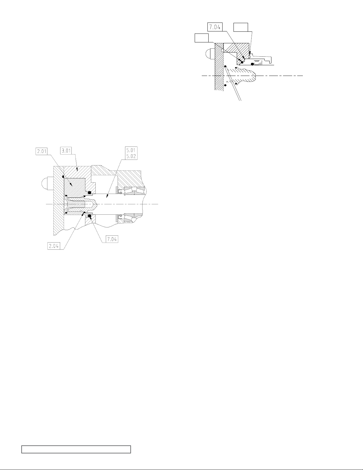
Figure 30
O-ring Seal
- Slide casing (3.01) from gearbox (4.01) noting it is located on
dowels (4.03), keep arch shims (4.05) in appropriate sets if
they are to be reused.
4.2.2.2 CP40 CASING
REMOVAL FOR PUMPS
FITTED WITH SINGLE
FLUSHED OR DOUBLE
FLUSHED MECHANICAL
SEALS
- Prior to removal of casing (3.01) remove seal housing screws
(7.10) and separate housing (7.06) from casing (3.01) noting
itislocatedondowels(7.09).
- Slide casing from bearing housing (4.01), noting it is lo
on dowels (4.03), keep arch shims (4.05) in appropriate sets
if they are to be re-used
Single Flushed Mechanical Seal as shown in Figure 31 and
see sections 5.2.3 for removal and 5.2.4 for replacement.
Double Flushed Mechanical Seal as shown in Figure 32 and
see section 5.2.7 for removal and 5.2.8 for replacement.
cated
Figure 31
Single Flushed Mechanical Seal - CP40
4.2.3 CP40 GEARBOX
DISASSEMBLY
(After completing 4.3.1 and 4.3.2) - See Figure 33.
Before proceeding with disassembly of the gearbox remove
product seals; refer to sections 5.0 for Mechanical Seals or
section 6.0 for O-ring seals.
The following procedure describes complete disassembly of
the gearbox, refer to Figure 33.
- Removedrivekey(6.12),oildrain(6.09)andbreatherplugs
(6.10), drain oil into suitable container and retain if later
inspection is required.
- Remove screws (6.11) and gearbox cover (6.00). The
gearbox cover (6.00) is located on dowels (6.06) and sealed
with suitable liquid sealer.
- Remove oil seal (6.03) from gearbox cover (6.00).
- Loosen by 2 full turns all screws in retainer (5.16). Once
done, the retainer may release its grip. If it does not become
free, remove the two screws, which differ in color (these may
also have a washer under the head). Once these screws are
removed, tapped holes will be revealed. Insert two jacking
M8 x 40 setscrews into the tapped holes and tighten until the
retainer’s grip is broken. Remove the retainer.
this is
SECTION TSM 285 ISSUE A PAGE 18 OF 36
Page 19

- Install spacers (5.17), tab washers (5.20) and lock nuts
(5.14) to shafts (5.01 and 5.02) tightening to correct torque,
refer to section 8.2. Secure tab washers.
- Install bearing (6.02) inner races to shafts (5.01 and 5.02)
positioning against shoulder on shaft.
- Install bearing (6.02) outer races and retaining rings (6.01)
to
gearbox (4.01).
- Install two bearing cups (5.05) to gearbox (4.01).
- Support gearbox (4.01) in a vertical position and install
shafts
(5.01 and 5.02) to gearbox (4.01).
- Install remaining bearing cups (5.05), shims (5.04) to nomi
nal
value of 0.6mm (0.024”), O-rings (5.21), retainers (5.06) and
secure with screws (5.07) tightening to correct torque, refer
to section 8.2.
- Using a torque wrench, check rolling torque of each shaft
assembly, refer to section 8.2, if necessary adjust amount of
shim (5.04) either by adding shim (5.04) to increase rolling
torque or removing shim (5.04) to decrease rolling torque until
correct rolling torque has been achieved. If shim is adjusted
ensure screws (5.07) are tightened to correct torque before
final check of rolling torque.
- Install rotors (2.01) onto shafts (5.01 and 5.02) with rotor
retainers (2.02).
Note: The socket tool (not shown) should
always be used to remove the retainer. The
use of other tools may damage the retainer.
- Using a depth micrometer or similar device measure any
difference (X) in rotor front face alignment, see Figure 35. If
a difference is found move shims (5.04) of thickness equal
- Remove lock nut (5.12) and tab washer (5.11).
- Removetiminggears(5.0---
to the difference (X) from beneath the lower rotors bearing
retainer (5.06) and reposition under the front bearing
(5.05) cup.
SECTION TSM 285 ISSUE A PAGE19 OF 36
Page 20
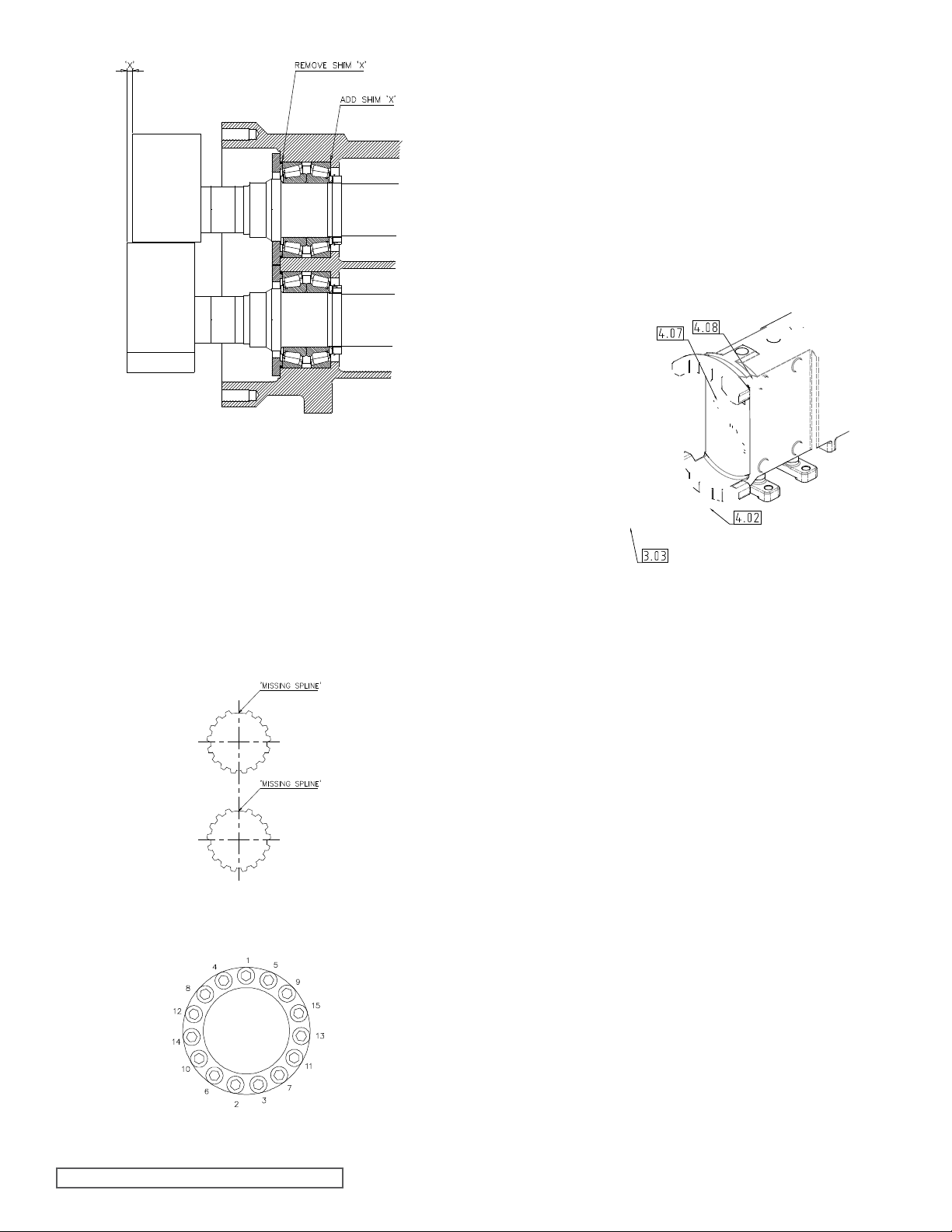
Figure 35
Rotor face alignment
- Lubricate retainer (5.16) with oil and mount to timing gear
(5.09).Donottighten.
- Install rotors (2.01) and rotor retainers (2.02) to shafts (5.01
and 5.02).
- Check rotor mesh clearance against Clearance Chart - refer
to section 8.1. To adjust the mesh clearance rotate shafts
(5.01 and 5.02). Having achieved optimum mesh clearance,
retainer (5.16) can be tightened to correct torque, refer to
section 8.2, taking note of typical tightening sequence, see
Figure 37.
- After tightening of retainer (5.16) check mesh clearance,
refer to section 8.1, Clearance Chart.
- Remove rotors (2.01) and retainers (2.02).
- Install oil seal (6.03) to gearbox cover (6.00).
- Apply liquid sealant (Loctite 573 or similar) to sealing
gearbox cover (6.00) and install to gearbox (4.01), locating
on dowels (6.06) and securing with screws (6.11), tightened
to correct torque, refer to section 8.2.
area of
4.2.5 CP40 CASING, ROTOR AND
HEAD ASSEMBLY
Figure 36
Missing spline alignment
Figure 37
Retainer Tightening Sequence
SECTION TSM 285 ISSUE A PAGE 20 OF 36
Figure 38
CP40 Casing Assembly
Page 21
- Install product seals; refer to section 5.0 or section 6.0.
- Install casing (3.01) to gearbox (4.01), noting it locates
dowels (4.03), securing with dome nuts (4.08).
- Install rotors (2.01) with O-rings (2.03 and 2.04) and retain
(2.02) tightening to correct torque, refer to section 8.2, using
socket tool supplied (not shown).
- Check all rotor clearances, front, rear, top/bottom, sides’
mesh, refer to section 8.1, Clearance Chart.
- Install head (1.01) with O-ring (1.02) and secure with
(1.03) tightened to correct torque, refer to section 8.2.
and
nuts
4.3 CP50 PUMPS - DISASSEMBLY
AND ASSEMBLY
4.3.1 CP50 HEAD AND
ROTOR REMOVAL
on
ers
- Remove rotor caps (2.02) with tool (supplied, not shown).
Note: The tool provided should always be
used to remove the rotor cap. The use of
other tools may damage the rotor cap.
- Remove rotor cap O-rings (2.03).
- Loosen by 2 full turns all screws in rotor retainer (2.05).
this is done the retainer may release its grip. If it does not,
loosen further the screws until the assembly becomes free
to remove.
(On some brands of locking device there are two screws that
are different in color (these may also have a washer under the
head). Once these screws are removed tapped holes will be
revealed. By inserting two jackscrews (M8 x 40 setscrews),
into the tapped holes and tightening, the retainer’s grip is
broken. Remove the retainers’ (2.05).
- Remove rotors (2.01) from shafts (5.01 and 5.02).
- Remove O-rings (2.04) and keys (2.06).
Once
4.3.2 CP50 CASING REMOVAL
Note: Ensure all pipe work is disconnected
before commencing casing removal.
4.3.2.1 CP50 CASING REMOVAL
FOR PUMPS FITTED WITH
SINGLE UN-FLUSHED
MECHANICAL SEALS
AND O-RING SEALS
(After completing 4.3.1)
- Remove dome nuts (4.08).
- Slide casing (3.01) from gearbox (4.01), noting it is
on dowels (4.03).
Single Un-ushed Mechanical Seals as shown in Figure 40
and see sections 5.3.1 for removal and 5.3.2 for replacement.
Single O-ring Seal for CP50 see Figure 41 and see section
6.3.1 for removal and replacement.
- Remove O-ring seal (7.04) from casing (3.01).
- Slide casing (3.01) from gearbox (4.01) noting it is lo
dowels (4.03).
located
cated on
Figure 39
Head and Rotor Components
Follow recommended shutdown procedure - refer
to section 3.5.
- RefertoFigure39.
- Gradually loosen head retaining dome
(1.03). Care should be taken as there may still
be residual product and pressure in the pump
head and as the dome nuts are loosened, this
will vent to atmosphere.
- Remove dome nuts (1.03).
- Remove head (1.01), using lever slots where neces
the head O-ring (1.02).
nuts
sary and
4.3.2.2 CP50 CASING REMOVAL
FOR PUMPS FITTED
WITH SINGLE FLUSHED
AND DOUBLE FLUSHED
MECHANICAL SEALS
- Refer to Figure 42 for Single flushed mechanical seal for
CP50.
- Refer to Figure 43 for Double flushed mechanical seal for
CP50.
- Prior to removal of casing (3.01), remove seal housing
(7.18) from studs (7.17) and separate housing (7.06) from
casing (3.01).
- Remove dome nuts (4.08).
- Slide casing from bearing housing (4.01), noting it is
on dowels (4.03).
SECTION TSM 285 ISSUE A PAGE 21 OF 36
nuts
located
Page 22
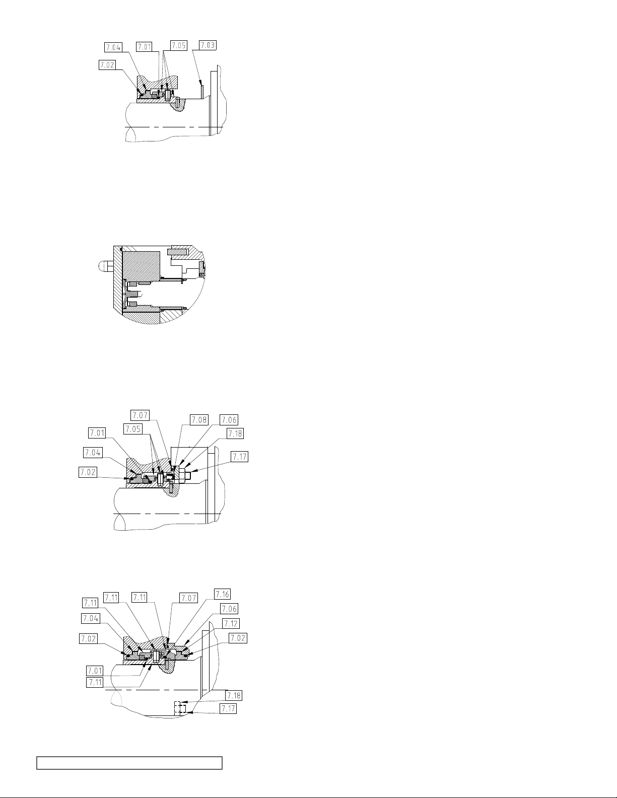
Figure 40
Single Un-ushed Mechanical Seal – CP50
4.3.3 CP50 GEARBOX
DISASSEMBLY
(After completing 4.3.1 and 4.3.2)
Before proceeding with disassembly of the gearbox remove
product seals; refer to section 5.3 for Mechanical Seals and
6.3 for O-ring Seals.
The following procedure describes complete disassembly of
the gearbox, refer to Figure 44.
- Remove guard (4.06) and shaft slingers (7.03) if fitted.
- Remove drive key (6.12).
- Remove oil drain plugs (6.09) and breather plugs (6.10),
drain oil into suitable container and retain (inspection may
later be required).
Figure 41
Single O-ring Seal CP50
Figure 42
Single Flushed Mechanical Seal for CP50
Figure 43
Double Flushed Mechanical Seal for CP50
- Remove screws (6.11) and gearbox cover (6.00). The
gearbox cover (6.00) is located on dowels (6.06) and sealed
with suitable liquid sealant.
- Remove oil seal (6.03) from gearbox cover (6.00).
- Loosen by two full turns all screws in retainer (5.16) on the
lay shaft (5.02). Once this is done the retainer may release
its grip. If it does not become free identify and remove the
three screws which differ in color (these may also have a
washer under the head). Once these screws are removed
tapped holes will be revealed. Insert three jackscrews (M10
x 40 setscrews), into the tapped holes and tighten until the
retainer’s grip is broken. Remove the retainer.
- Remove lock nut (5.12) and tab washer (5.11), then remove
timing gears (5.09), gear key (5.10), spacer (5.18), O-ring
(5.22) and lipseal (83).
SECTION TSM 285 ISSUE A PAGE 22 OF 36
Page 23
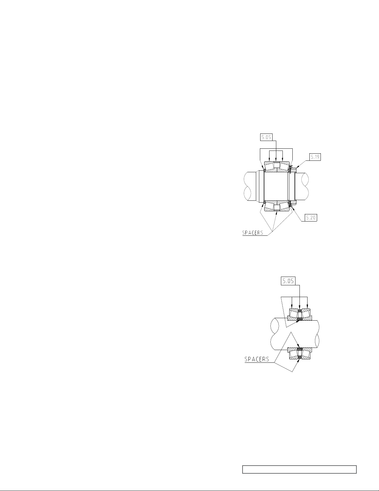
- Support pump with shafts in the vertical position with rotor
end up.
- Remove screws (5.07), and then remove bearing retainers’
(5.06) and O-rings (5.21), then remove lipseals (5.03) from
bearing retainers’ (5.06).
- Remove shafts (5.01 and 5.02) from gearbox (4.01). Shafts
(5.01 and 5.02) will be complete with pins (5.23), spacers
(5.24), bearings (5.05), spacers (5.05), tab washers (5.20),
locknuts(5.19),bearings(6.02)andspacers(6.02).
- Remove bearings (6.02) complete with spacers (6.02) from
shafts (5.01 and 5.02) keep them in matched sets and identify
position.
- Removelocknuts(5.19)andtabwashers’(5.07).
- Remove bearings (5.05) complete with spacers (5.05) from
shafts (5.01 and 5.02), keep them in matched sets and
identify position.
- Remove shaft sleeve drive pins (5.23) from shafts (5.01 and
5.02), remove spacers (5.24), note fitting position.
4.3.4 CP50 GEARBOX ASSEMBLY
The following procedure describes the assembly of the gearbox,
refer to Figure 44.
- Install bearings (5.05) complete with spacers (5.05) to
shafts (5.01 and 5.02) ensuring correct positioning of all
components as either removed in 4.3.3. Above or supplied
as new replacement set, see Figure 45.
- Install spacers (5.24), product seal sleeves (28 or 66), ro
keys (78) and rotors (41) to shafts (5.01 and 5.02) and secure
with rotor retainers (35) using tool (58).
- Install tabwashers (5.07)andlocknuts(5.19)tighteningto
correct torque, refer to section 8.2. Secure tab washers.
Note: Ensure that the cups of the rear most bearings (5.05)
are in position on inner races before proceeding.
- Install bearings (6.02) complete with spacers (6.02) to
shafts (5.01 and 5.02) ensuring correct positioning of all
components as either removed in 4.3.3 above or as supplied
as new replacement set, see Figure 46.
- Support gearbox (4.01) in a vertical position and install
(5.01 and 5.02) to gearbox (4.01).
- If not already installed install cups of front most bearings
(5.05).
- Installlipseals(5.03)tobearingretainers’(5.09).
- Install retainers’ (5.09) and O-rings (5.21) and secure with
screws (5.07) tightening to correct torque, refer to section
8.2.
- Return pump to normal horizontal mounting position.
- Installlipseal(6.19)togearbox(4.01).InstallO-ring(5.22),
spacer (5.18) and key (5.10) to drive shaft (5.01).
- Installtiminggears(5.09)toshafts(5.01and5.02).
- Install tab washer (5.11) and lock nut (5.12) tightening to
correct torque, refer to section 8.2. Secure tab washer
(5.11).
- Rotate shafts (5.01 and 5.02) such that keyways for rotor
keys are vertically upwards.
- Lubricate retainer (5.16) with oil and install to timing gear
(5.09).Donottighten.
tor
shafts
Note: Pins (5.23) should not be installed at this stage.
- Clamp gear (5.09)toshaft(5.02) using tool(supplied)
associated stud and nut, ensuring that two screws in retainer
(5.16) are visible through holes in tool.
- Check rotor mesh clearance against Clearance Chart,
refer to section 8.1. Adjustment of mesh clearance is made
by rotating the shafts (5.01 and 5.02). Having achieved
optimum mesh clearance, partially tighten visible screws
in retainer (5.16), to clamp gear in place. Remove tool and
associated studs and nuts. Fully tighten screws in retainer
(5.16) to correct torque, refer to section 8.2, taking note of
typical tightening sequence, see Figure 47.
- After tightening of retainer (5.16) check rotor mesh clear
refer to section 8.1 (Clearance Chart).
Figure 45
Front Bearing Assembly - CP50
Figure 46
Rear Bearing Assembly - CP50
and
ance;
SECTION TSM 285 ISSUE A PAGE 23 OF 36
Page 24
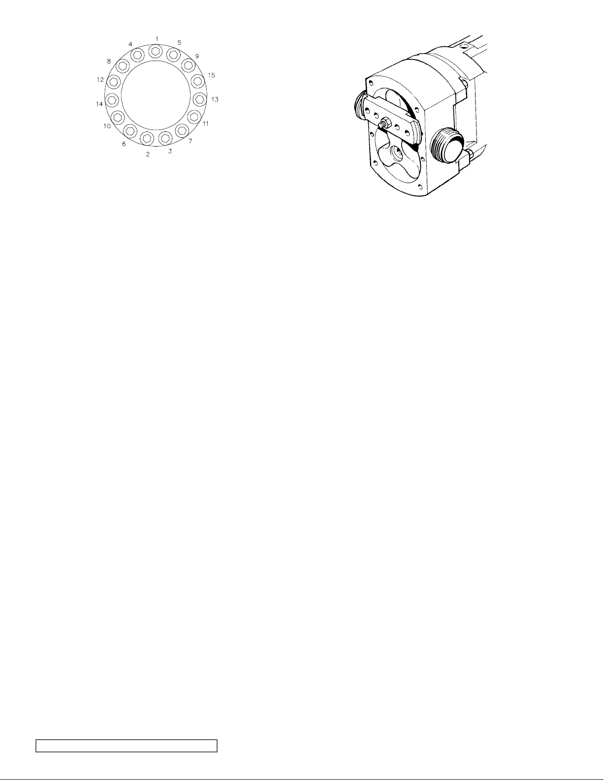
Figure 47
Retainer Tightening Sequence
- Install oil seal (6.03) to gearbox cover (6.00).
- Apply liquid sealant (Loctite 573 or similar) to sealing
gearbox cover (6.00) and install to gearbox (4.01), locating
on dowels (6.06) and securing with screws (6.11), tightened
to correct torque, refer to section 8.2.
- Install drive key (6.12).
- Installdrainplugs(6.09)andbreatherplugs(6.10).
- Remove rotor retainers (2.02) using tool, rotors (2.01) and
spacers (5.24)
area of
4.3.5 CP50 CASING, ROTOR AND
HEAD ASSEMBLY
Referring to Figure 33 and Figure 44.
- Install spacers’ (5.24) and product seal sleeves (7.15) to
shafts (5.01 and 5.02).
Note: Pins (5.23) should not be installed at this stage.
- Install casing (3.01) to gearbox (4.01) locating on dowels
(4.03) and secure with dome nuts (4.08) tightened to correct
torque, refer to section 8.2.
- Install rotors (2.01) to shafts (5.01 and 5.02).
- Clamp one rotor (2.01) to shaft (5.01 or 5.02) using tool and
associated stud and nut see Figure 48.
- Using a depth micrometer or similar device, measure front
clearance; refer to section 8.1, Clearance Chart, between
the casing and clamped rotors front face and check that this
corresponds to the appropriate clearance as indicated on the
Clearance Chart. Note any discrepancy in front clearance.
- Remove tool and associated stud and nut (shown above).
- Repeat clamping and front clearance measurement for
rotor (again note any discrepancy in front clearance.
- Remove tool and associated stud and nut.
- Remove rotors (2.01), casing (3.01) and product seal
(7.15).
- If any discrepancies were noted in front clearances,
rotors and front face of casing, then spacers (5.24) will
require machining to shorten them to achieve the correct
front clearance, refer to section 8.1.
Note: If it is found that the measured front clearance is
greater than that shown in the Clearance Chart, refer
to section 8.1, then new spacers (5.24) will need to be
obtained and machined to the correct lengths to achieve
correct front clearance.
other
sleeves
between
Figure 48
Rotor Clamping Tool Fitment
- Be sure faces of spacers’ (5.24) are parallel after
machining.
- After any machining of spacers’ (5.24), check front clear
for both rotors, refer to section 8.1, Clearance Chart.
- Install spacers (5.24) to shafts (5.01 and 5.02) ensuring
are correctly located.
- Install pins (5.23) to shafts (5.01 and 5.02) using a liquid
retainer (Loctite 648 or similar).
- Install product seals; refer to section 5.3 and 6.3.
- Install casing (3.01) to gearbox (4.01) locating onto
(4.03) and securing with dome nuts (4.08) tightened to
correct torque, refer to section 8.2.
- Install O-rings (2.05) and rotors (2.01) to shafts (5.01 and
5.02).
- Lubricate retainers’ (53) with oil and install to shafts (5.01
and 5.02).
- Clamp one rotor (2.01) to shaft (5.01 or 5.02) using tool and
associated stud and nut, see Figure 48, ensuring that two
of the screws in retainer (2.05) are visible through holes in
tool.
- Moderately tighten visible screws in retainer (2.05) in
rotor to lock rotor in position. Remove tool and associated
stud and nut, tighten fully screws in retainer (2.05) to correct
torque, refer to section 8.2, taking note of typical tightening
sequence, see Figure 47.
- Repeat clamping and retainer (2.05) tightening procedure
other rotor.
- Remove tool and associated stud and nut.
- Install O-rings (2.03) and retainers (2.02) tightening to cor
torque refer to section 8.2, using tool.
- Check all rotor clearances, front, rear, top/bottom, sides’
mesh, refer to section 8.1, Clearance Chart.
- Install head (1.01) with O-ring (1.02) and secure with
(1.03) tightened to correct torque, refer to section 8.2.
ances
they
dowels
clamped
for
rect
and
nuts
SECTION TSM 285 ISSUE A PAGE 24 OF 36
Page 25
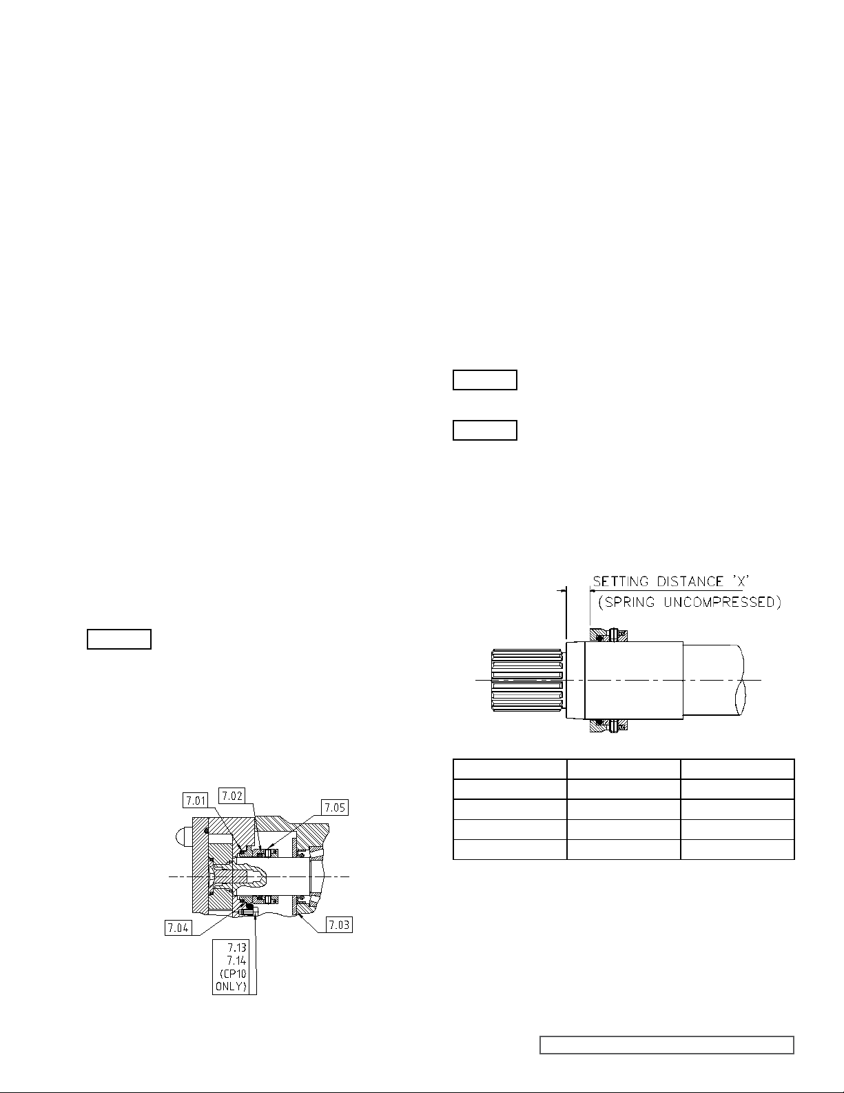
5.0 CLASSIC+ MECHANICAL SEAL
REMOVAL & REPLACEMENT
5.1 GENERAL PROCEDURES FOR
INSTALLING MECHANICAL
SEALS
“Quick summary” of mechanical seal installation
- Mechanical seals are precision-engineered assemblies
incorporating finely lapped seal faces and seats. They must
be handled with care and will not give optimum performance
unless installed carefully and according to instructions.
- When mechanical seals are to be reused, ensure seal
components are kept in their appropriate sets. Do not mix
old and new seal faces on the same seal.
- Remove any sharp corners and burrs that may damage any
elastomers such as O-rings or lipseals.
- Be sure that all seal component fitting bores and housings
are thoroughly cleaned before installation.
- The seal faces and seats must be handled with care and
cleaned thoroughly before installation.
- Be sure that seal faces are undamaged and the O-rings are
not cut, swollen or cracked.
- All O-rings should be lightly lubricated with a suitable
lubricant (silicon grease, soap etc.) before installation but
ensure there is no excessive amount of lubricant especially
around the seal face area.
- Ensure when installing seals with brittle faces and seats
such as silicon carbide that extra care is taken.
- Do not use any excessive force to install a mechanical
seal. If it is difficult to position and assemble the seal then
something is wrong.
- If you drop or damage a seal, do not install it before an
inspection has been carried out.
WARNING
- Do not run a mechanical seal dry.
- Remove head (1.01), rotor retainers (2.02), O-rings (2.04)
and casing (3.01), refer to section 4.1.2.1 (CP10, CP20 and
CP30) or section 4.2.2.1 (CP40).
- Loosen but do not remove screws in rotary cartridge as
(7.05) which secure rotary seal cartridges to shafts (5.01 and
5.02).
- Remove rotary seal cartridges (7.05) with O-ring (7.02) from
shafts (5.01 and 5.02).
- Remove stationary seal seats (7.04) and O-rings (7.01)
casing (3.01).
sembly
from
5.2.2 CP10, CP20, CP30 AND CP40
SINGLE MECHANICAL SEAL
REPLACEMENT
Refer to Figure 50 for CP10, CP20, CP30 and CP40
- Install O-rings (7.01) to stationary seal seat (7.04).
- Install stationary seal seats (7.04) to casing (3.01)
correct location of O-rings (7.01).
WARNING
WARNING
- Install rotary seal cartridges (7.05) with O-ring (7.02) to
shafts (5.01 and 5.02) positioning to correct setting distance,
see Figure 50 and tighten screws (7.05) to correct torque,
refer to section 8.2.
Note: On CP10 models the stationary seal
seat (7.04) has a location recess which fits
over the anti-rotation washer (7.13).
Note: On CP20, CP30 and CP40 models the
stationary seal seat (7.04) has a triangular
shape, which must locate fully into the casing
(3.01) bore.
ensuring
5.2 CP10, CP20, CP30 AND CP40
MECHANICAL SEALS
5.2.1 CP10, CP20, CP30 AND CP40
SINGLE MECHANICAL SEAL
REMOVAL
Figure 49
Single Un-ushed Mechanical Seal
Pump Model X (mm) X (inches)
CP10 14.3 0.5630
CP20 10.8 0.4252
CP30 13.4 0.5276
CP40 17.5 0.6890
Figure 50
Setting Distance for Seals
- Install casing (3.01), O-rings (2.04), rotors (2.01), O-rings
(2.03), rotor retainers (2.02) and head (1.01), refer to sections
4.1.4 (CP10, CP20 and CP30) or 4.2.5 (CP40).
SECTION TSM 285 ISSUE A PAGE 25 OF 36
Page 26
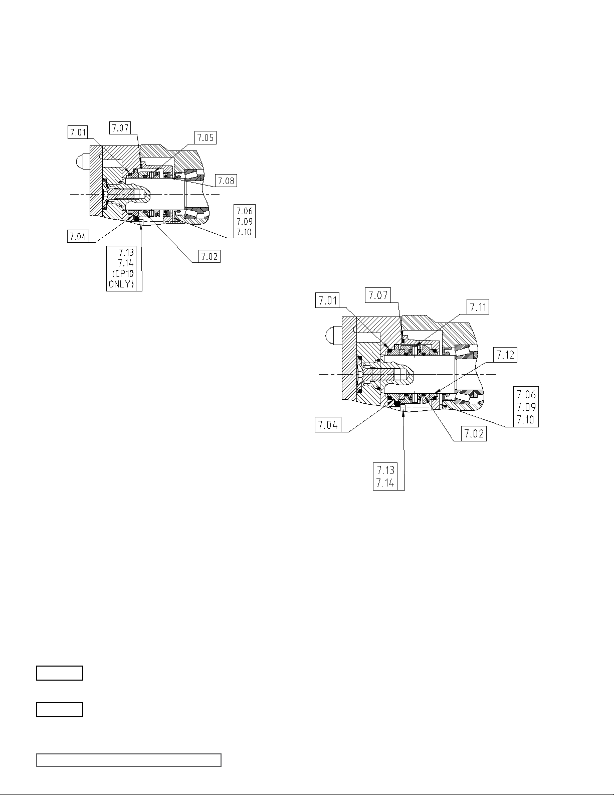
5.2.3 CP10, CP20, CP30 AND CP40
SINGLE FLUSHED
MECHANICAL SEAL REMOVAL
Refer to Figure 51 for CP10, CP20, CP30 and CP40
Figure 51
Single Flushed Mechanical Seal
- Install lipseals (7.08) and O-rings (7.07) to housing(s)
(7.06).
- Install housing(s) (7.06) to shafts (5.01 and 5.02).
- Install rotary seal cartridges (7.05) to shafts (5.01 and 5.02)
positioning to correct setting distance, see Figure 50 and
tightening screws in rotary seal cartridge assemblies (7.05)
to correct torque, refer to section 8.2.
Note: Access to screws in rotary cartridge seal assemblies
(7.05) is through the ush pipe connections of housing
(7.06).
- Install casing (3.01), O-rings (2.04), rotors (2.01), O-rings
(2.03), rotor retainers (2.02) and head (1.01), refer to sections
4.1.4 (CP10, CP20 and CP30) or 4.2.5 (CP40).
- Secure housing(s) (7.06) to casing (3.01) with screws
ensuringcorrectlocationontodowels(7.09).
(7.10)
5.2.5 CP10 DOUBLE FLUSHED
MECHANICAL SEAL REMOVAL
Refer to Figure 52.
- Remove head (1.01), rotor retainers’ (2.02), O-rings
rotors (2.01), O-rings (2.04) and casing (3.01), refer to
sections 4.1.2.1 and 4.1.2 (CP10, CP20 or CP30) or 4.2.2.1
(CP40).
- Loosen but do not remove screws in rotary seal cartridge
assemblies (7.05), which secure rotary seal cartridges to
shafts (5.01 and 5.02).
Note: Access to screws in rotary seal cartridge (7.05) is
through the ush pipe connections of housing (7.06).
- Remove rotary seal cartridges (7.05) with O-ring (7.02) from
shafts (5.01 and 5.02).
- Remove housing(s) (7.06) complete with lipseals (7.08) and
O-Ring(s) (7.07) from shafts (5.01 and 5.02).
- Remove lipseals (7.08) and O-ring (s) (7.07) from
(7.06).
- Remove stationary seal seats (7.04) and O-rings (7.01)
casing (3.01).
(2.03),
housing(s)
from
5.2.4 CP10, CP20, CP30 AND CP40
SINGLE FLUSHED
MECHANICAL SEAL
REPLACEMENT
Refer to Figure 51 for CP10, CP20, CP30 and CP40
- Install O-rings (7.01) to stationary seal seats (7.04).
- Install stationary seal seats (7.04) to casing (3.01)
correct location of O-rings (7.01).
WARNING
WARNING
Note: On CP10 models the stationary seal
seat (7.04) has a location recess which fits
over the anti-rotation washer (7.13).
Note: On CP20, CP30 and CP40 models the
stationary seal seat (7.04) has a triangular
shape, which must locate fully into the casing
(3.01) bore.
ensuring
Figure 52
Double Flushed Mechanical Seal
- Remove head (1.01), rotor retainers’ (2.02), O-rings
rotors (2.01), O-rings (2.04) and casing (3.01), refer to
sections 4.1.1 and 4.1.2.
- Loosen but do not remove screws (7.11), which secure
seal cartridge assemblies (7.11) to shafts (5.01 and 5.02).
Note: Access to screws (7.13) is through the ush pipe
connections of housing (7.06)
- Remove rotary seal cartridges (7.11) with O-rings (7.02)
shafts (5.01 and 5.02).
- Remove housing (7.06) complete with O-ring (7.07),
stationary seal seats (7.12) and O-rings (7.01) from shafts
(5.01 and 5.02).
- Remove stationary seal seats (7.12), O-rings (7.01) and
ring (7.07) from housing (7.06).
- Remove stationary seal seats (7.04) and O-rings (7.01)
casing (3.01).
(2.03),
rotary
from
O-
from
SECTION TSM 285 ISSUE A PAGE 26 OF 36
Page 27
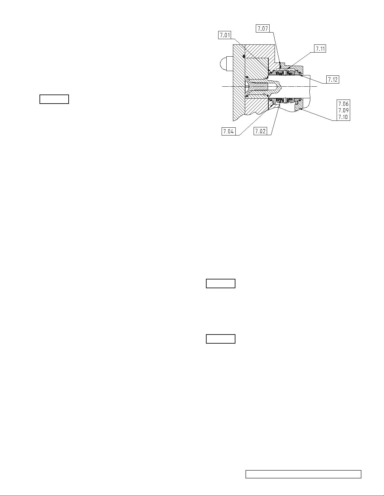
5.2.6 CP10 DOUBLE FLUSHED
MECHANICAL SEAL
REPLACEMENT
Refer to Figure 52
- Install O-rings (7.01) to stationary seal seats (7.04 and
7.12).
- Install stationary seal seats (7.04) to casing (3.01)
correct location of O-rings (7.01).
WARNING
- Install O-rings (7.01) to stationary seal seats (7.11).
- Install stationary seal seats (7.11) to housing (7.06) ensur
correct location of O-ring (7.01).
- Install housing (7.06) to shafts (5.01 and 5.02).
- Clean faces of outboard seal (7.11 and 7.12) use a soft tis
and suitable solvent based cleaner for best results.
- Install rotary seal cartridges (7.11) with O-ring (7.02) to
(5.01 and 5.02).
Note: For pumps installed with ange type casing (3.01)
connections, it may be easier to set the position of the
rotary seal cartridge (7.11) onto the shafts (5.01 and
5.02) using the setting distance, see gure 50, before
installing the casing (3.01). Screws in rotary seal cartridge
assemblies (7.11) must be tightened to the correct torque
refer to section 8.2.
- Install casing (3.01), O-rings (2.04), rotors (2.01), O-rings
(2.03), rotor retainers (2.02) and head (1.01) - refer to section
4.1.4.
- Secure housing (7.06) to casing (3.01) with screws
ensuringcorrectlocationontodowels(7.09).
- Rotate pump shafts by two or three full revolutions.
- If not already tightened, tighten screws (7.11) to correct
torque, refer to section 8.2.
Note: Access to screws (7.11) is through the ush pipe
connections of housing (7.06)
Note: The stationary seal seat (7.04) has
a location recess which fits over the antirotation washer (7.13).
ensuring
ing
sue
shafts
(7.10)
5.2.7 CP20, CP30 AND CP40
DOUBLE FLUSHED
MECHANICAL SEAL REMOVAL
- Remove head (1.01), rotor retainers’ (2.02), O-rings (2.03),
rotors (2.01), O-rings (2.04) and casing (3.01), refer to
sections 4.1.1 and 4.1.2 (CP20/CP30) or sections 4.2.1 and
4.2.2 (CP40).
- Loosen but do not remove screws in rotary seal cartridge
assemblies (7.11), which secure rotary seal cartridge
assemblies (7.11) to shafts (5.01 and 5.02).
Note: Access to screws (7.11) is through the ush
connections of housings (7.06).
- Remove rotary seal cartridge assemblies (7.11) with O-ring
(32) from shafts (5.01 and 5.02).
- Remove housings (7.06) from shafts (5.01 and 5.02)
complete with stationary seal seats (7.12), O-rings (7.01)
and O-rings (7.07).
Figure 53
Double Flushed Mechanical Seal
- Remove stationary seal seats (7.04), O-rings (7.01) and
rings (7.07) from housings (7.06).
- Remove stationary seal seats (7.04) and O-rings (7.01)
casing (3.01).
O-
from
5.2.8 CP20, CP30 AND CP40
DOUBLE FLUSHED
MECHANICAL SEAL
REPLACEMENT
Refer to Figure 53.
- Install O-rings (7.01) to stationary seal seats (7.04).
- Install stationary seal seats (7.04) to casing (3.01)
correct location of O-rings (7.01).
WARNING
- Install O-rings (7.01) to stationary seal seats (7.12).
- Install stationary seal seats (7.12) to housings (7.06) ensur
both correct locations of O-ring (7.01) and stationary seal
seats (7.04) in housings (7.06).
WARNING
- Install housings (7.06) to shafts (5.01 and 5.02).
- Clean faces of outboard seal (7.11 and 7.12) use a soft tis
and a suitable solvent based cleaner for best results.
- Install rotary seal cartridge assemblies (7.11) to shafts (5.01
and 5.02).
Note: For pumps installed with ange type casing (3.01)
connections, it may be easier to set the position of the
rotary seal cartridge (7.11) onto the shafts (5.01 and
5.02) using the setting distance, see Figure 50, before
installing the casing (3.01). Screws in rotary seal cartridge
assemblies (7.11) must be tightened to the correct torque
refer to section 8.2.
Note: The stationary seal seats (7.04) have a
triangular shape which must locate fully into
the casing (3.01) bore.
Note: The stationary seal seats (7.12) have a
triangular shape which must locate fully into
the housing (7.06) bore.
ensuring
ing
sue
SECTION TSM 285 ISSUE A PAGE 27 OF 36
Page 28
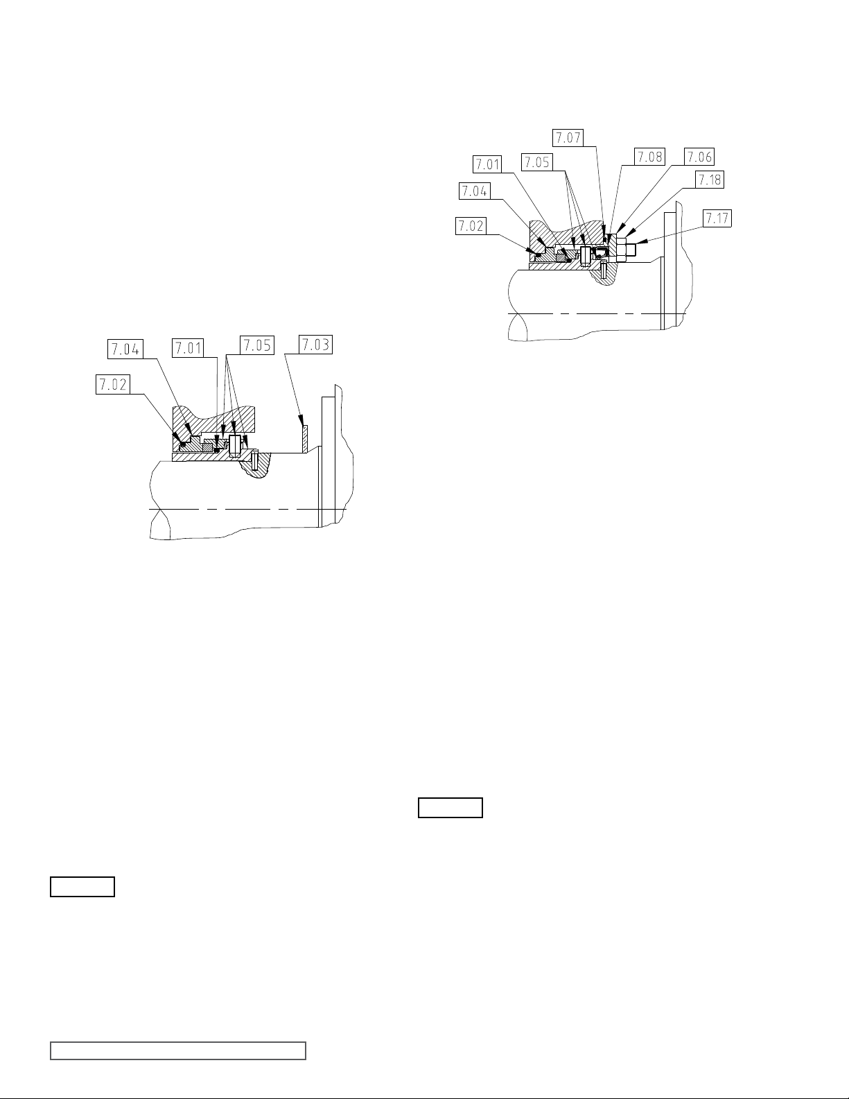
- Install casing (3.01), O-rings (2.04), rotors (2.01), O-rings
(2.03), rotor retainers (2.02) and head (1.01) refer to sections
4.1.4 (CP20/CP30) or 4.2.5 (CP40).
- Secure housings (7.06) to casing (3.01) with screws
ensuringcorrectlocationontodowels(7.09).
- Rotate pump shafts by two or three full revolutions.
- If not already tightened, tighten screws in rotary seal car
assemblies (7.11) to correct torque, refer to section 8.2.
Note: Access to screws in rotary seal cartridge assemblies
(7.11) is through the ush connections of housings (7.06).
(7.10)
tridge
5.3 CP50 MECHANICAL SEALS
5.3.1 CP50 SINGLE MECHANICAL
SEAL REMOVAL
Figure 54
Single Un-Flushed Mechanical Seal CP50
- Remove head (1.01), rotor caps (2.02), O-rings (2.03),
retainers’ (2.05), rotors (41), O-rings (2.04) and casing
(3.01), refer to sections 4.3.1 and 4.3.2.
- Remove rotary seal cartridge assemblies (7.11) with O-ring
(7.01) from shafts (5.01 and 5.02) by simply sliding off.
Do not loosen screws in rotary seal cartridge assemblies
(7.05).
- Remove stationary seal seats (7.04) and O-rings (7.02)
from casing (3.01).
5.3.2 CP50 SINGLE MECHANICAL
SEAL REPLACEMENT
- Install O-rings (7.02) to stationary seal seats (7.04).
- Install stationary seal seats (7.04) to casing (3.01)
correct location of O-rings (7.02).
WARNING
- Install rotary seal cartridge assemblies (7.11) with O-ring
(7.01) to shafts (5.01 and 5.02) ensuring engagement of
drive slots with pins (5.23) in shafts (5.01 and 5.02).
- Install casing (3.01), O-rings (2.04), rotors (2.01),
(2.05), O-rings (2.03), rotor caps (2.02) and head (1.01)
- refer to section 4.3.5.
Note: The stationary seal seat (7.04) has a
triangular shape, which must locate fully into
the casing (3.01), bore.
ensuring
retainers
5.3.3 CP50 SINGLE FLUSHED
MECHANICAL SEAL REMOVAL
Refer to Figure 55.
Figure 55
Single Flushed Mechanical Seal CP50
- Remove head (1.01), rotor caps (2.02), O-rings (2.03),
retainers (2.05), rotors (2.01), O-rings (2.04) and casing
(3.01) refer to sections 4.3.1 and 4.3.2.
- Remove rotary seal cartridge assemblies (7.05) with O-ring
(7.01) from shafts (5.01 and 5.02) by simply sliding off.
Do not loosen screws in rotary seal cartridge assemblies
(7.05).
- Remove housings (7.06) complete with lipseals (7.08) and
O-rings (7.07) from shafts (5.01 and 5.02).
- Remove lipseals (7.08) and O-rings (7.07) from housings
(7.06).
- Remove stationary seal seats (7.04) and O-rings (7.02) from
casing (3.01).
5.3.4 CP50 SINGLE FLUSHED
MECHANICAL SEAL
REPLACEMENT
Refer to Figure 55
- Install O-rings (7.02) to stationary seal seats (7.04).
- Install stationary seal seats (7.04) to casing (3.01)
correct location of O-rings (7.02).
WARNING
- Install lipseals (7.08) and O-rings (7.07) to housings (7.06).
- Install housings (7.06) to shafts (5.01 and 5.02).
- Install rotary seal cartridge assemblies (7.05) with O-ring
(7.01) to shafts (5.01 and 5.02) ensuring engagement of
drive slots with pins (5.23) in shafts (5.01 and 5.02).
- Install casing (3.01), O-rings (2.04), rotors (2.01), retain
(2.05), O-rings (2.03), rotor caps (2.02) and head (1.01) refer to section 4.3.5.
- Secure housings (7.06) to casing (3.01) with nuts (7.18).
Note: The stationary seal seat (7.04) has a
triangular shape, which must locate fully into
the casing (3.01), bore.
ensuring
ers
SECTION TSM 285 ISSUE A PAGE 28 OF 36
Page 29
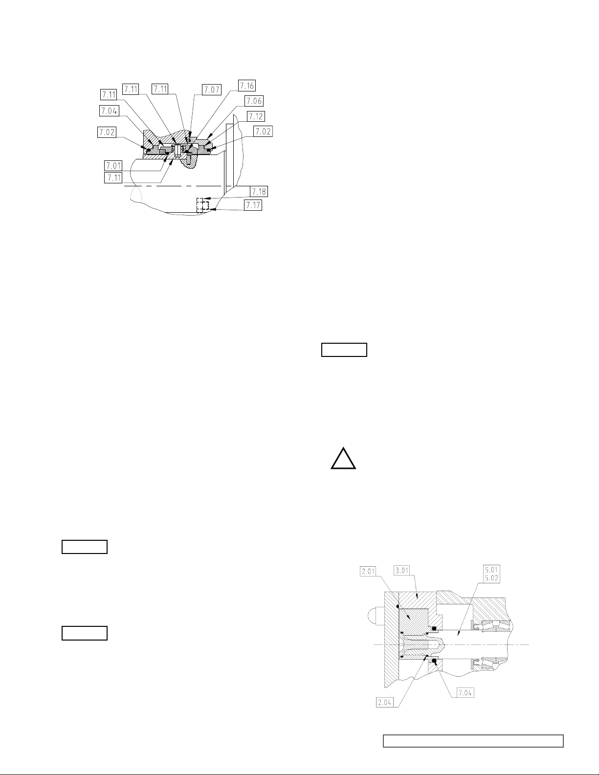
5.3.5 CP50 DOUBLE FLUSHED
MECHANICAL SEAL REMOVAL
Figure 56
Double ushed mechanical seal CP50
- Remove head (1.01), rotor caps (2.02), O-rings (2.03),
retainers (2.05), rotors (2.01), Orings (2.04) and casing
(3.01), refer to sections 4.3.1 and 4.3.2.
- Remove rotary seal cartridge assemblies (7.11) with O-rings
(7.01) and (7.16) from shafts (5.01 and 5.02) by simply sliding
off. Do not loosen screws in rotary seal cartridge assemblies
(7.11).
- Remove housings (7.06) from shafts (5.01 and 5.02)
complete with stationary seal seats (7.04), O-rings (7.02)
and O-rings (7.07).
- Remove stationary seal seats (7.04), and O-rings (7.07) from
housings (7.06).
- Remove stationary seal seats (7.04) and O-rings (7.02) from
casing (3.01).
5.3.6 CP50 DOUBLE FLUSHED
MECHANICAL SEAL
REPLACEMENT
Refer to Figure 56.
- Install O-rings (7.02) to stationary seal seats (7.04).
- Install stationary seal seats (7.04) to casing (3.01)
correct location of O-rings (7.02).
WARNING
- Install O-rings (7.02) to stationary seal seat (7.04).
- Install stationary seal seats (7.04) to housings (7.06) ensur
correct locations of O-rings (7.02) and stationary seal seats
(7.04) in housings (7.06).
WARNING
- Install housings (7.06) to shafts (5.01 and 5.02).
- Clean faces of outboard seal (7.11 and 7.04) use a soft tis
and a suitable solvent based cleaner for best results.
- Install rotary seal cartridge assemblies (7.11) with O-
and (7.16) to shafts (5.01 and 5.02) ensuring engagement
of drive slots with pins (5.23) in shafts (5.01 and 5.02).
Note: The stationary seal seat (7.04) has a
triangular shape, which must locate fully into
the casing (3.01), bore.
Note: The stationary seal seat (7.04) has a
triangular shape, which must locate fully into
the housing (7.06), bore.
ensuring
ing
sue
ring (7.01)
- Install casing (3.01), O-rings (2.04), rotors (2.01), retain
(2.05), O-rings (2.03), rotor caps (2.02) and head (1.01),
refer to section 4.3.5.
- Secure housings (7.06) to casing (3.01) with nuts (7.18).
ers
6.0 CLASSIC+ SINGLE O-RING
SEALS
6.1 GENERAL PROCEDURES
FOR FITTING SINGLE O-RING
SEALS
“Quick Summary” of O-Ring seal installation.
- O-ring seals are a simple but effective means of shaft seal
They will provide optimum performance only if installed
carefully in accordance to the following instructions below
and sections 6.2 and 6.3.
- Remove any sharp corners and burrs that could damage
O-rings.
- Always inspect for wear, the diameter on the rotor where the
O-ring seal is located.
- Be sure that all seal component fitting bores, housings,
followers, sleeves etc. are thoroughly cleaned before
installation.
- All O-rings should be lightly lubricated with an appropriate
lubricant (suitable for application) before installation.
WARNING
Note: Do not run an O-ring seal dry.
ing.
6.2 O-RING SEALS FOR CP10,
CP20, CP30 AND CP40 PUMPS
6.2.1 CP10, CP20, CP30 AND CP40
O-RING SEAL ASSEMBLY
AND REMOVAL
- Before assembly or disassembly of the seals,
!
- Install O-ring (7.04) into the casing (3.01).
- Install O-ring (2.04) onto shaft (5.01 and 5.02).
Note: During installing of the rotors to shafts care must
be taken not to damage or unseat the O-ring seal when
inserting the rotor (2.01) into O-ring (7.04).
- To disassemble reverse the above procedure.
ensure pump is fully shutdown, refer to section
3.5.
Figure 57
O-Ring Seal for a CP10, CP20, CP30 and CP40
SECTION TSM 285 ISSUE A PAGE29 OF 36
Page 30
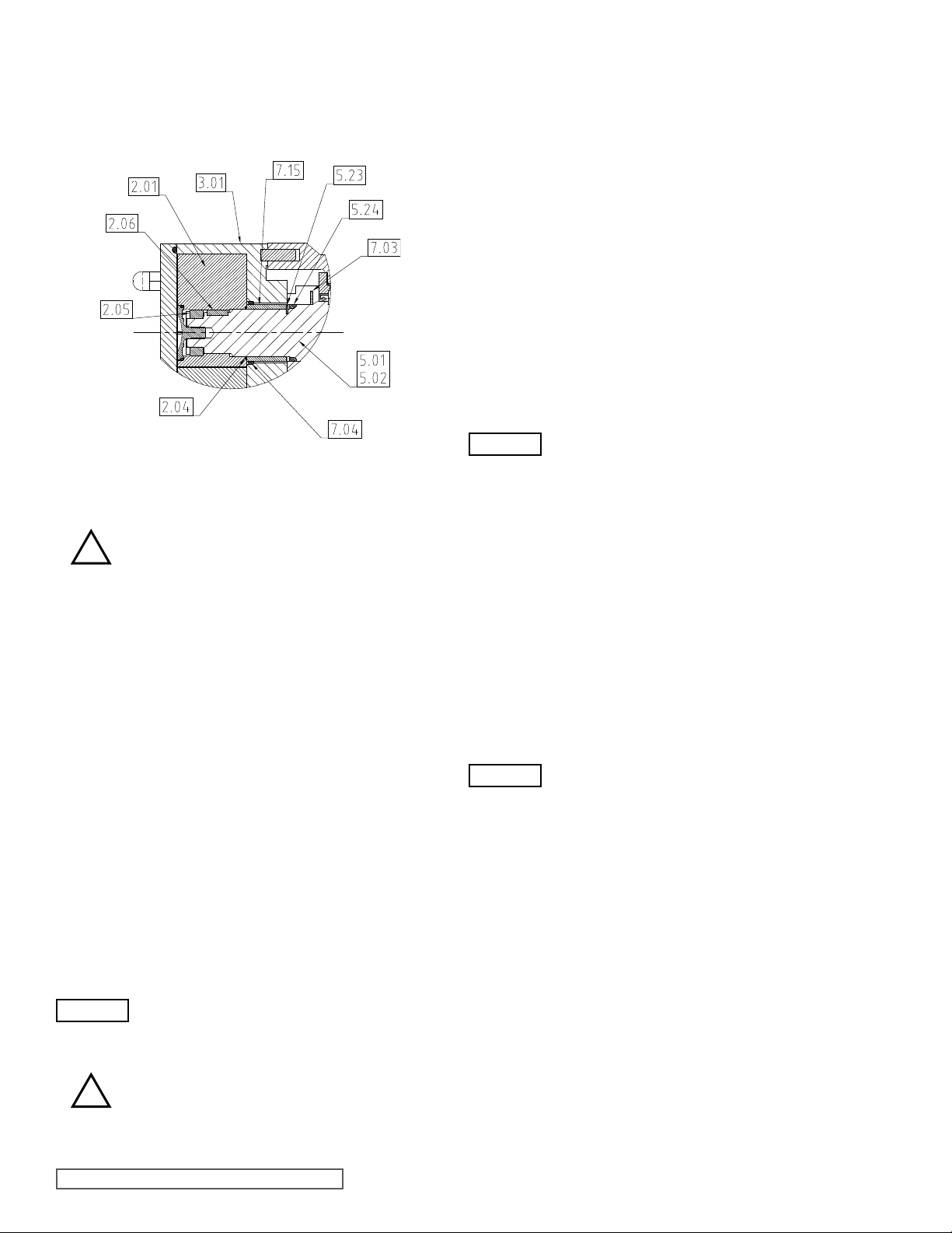
6.3 O-RING SEAL FOR CP50 PUMP
6.3.1 CP50 O-RING SEAL ASSEMBLY
AND REMOVAL
Figure 58
CP50 O-ring Seal
- Before assembly or disassembly of the seals,
!
- Install O-ring (7.04) into the casing (3.01).
- Install rotary seal sleeves (7.15) onto shafts (5.01 and 5.02),
ensuring engagement of slots in rotary seal sleeves (7.15)
and drives pins (5.230
- Install O-ring (2.04 onto shaft (5.01 and 5.02).
Note: During installing of the rotors to shafts care must
be taken not to damage or unseat the O-ring seal when
inserting the rotor (2.01) into O-ring (7.04).
- To disassemble reverse the above procedure.
ensure pump is fully shutdown, refer to
section 3.5.
7.0 FLUSHED PRODUCT SEALS
AUXILIARY SERVICES
i) Terminology.
a) “Quench”
- To provide a liquid barrier that is not induced to flow
through the seal area by any external means.
b) “Flush”
- To provide a liquid barrier that is induced to flow
through the seal area by an external means.
Quench or Flush Media
ii)
WARNING
!
The media used for quenching or flushing a seal
area must be fully compatible with the pumped
media, and the relevant materials of construction
of the pump.
Special consideration must be given to the
temperature limitations of the media to ensure
that no hazards are created, e.g. risk of fire or
explosion.
7.1 SINGLE MECHANICAL SEAL
(FOR LOW-PRESSURE
QUENCH OR FLUSH)
See Figure 17 (CP10), Figure 27 (CP20, CP30, CP40) and
Figure 50 (CP50).
Refer to section 4.3.3.
This seal arrangement requires a supply of media to the
outboard side of the mechanical seal to quench or ush the
sealarea.Thenatureofthe pumped media and the specic
dutyconditionswill determinewhethera quenchoraush is
required.
A quench provides a static head. The quench media vessel
should be mounted a minimum of 0.5m (1.5 Feet) above
the pump, preferably directly above the seal area. The
interconnecting pipe work should be as straight as possible,
avoiding horizontal runs, and with the minimum number of
bends and restrictions.
Forasuitableush,themediamustbesuppliedataowrate
of 4.5 Liters per minute per shaft seal.
WARNING
Note: The limiting flush or quench pressure
in any application is 0.7 Bar (10 psig).
7.2 DOUBLE MECHANICAL SEAL
(FOR HIGH PRESSURE FLUSH)
See Figure 18 (CP10) and Figure 28 (CP20, CP30, CP40) and
Figure 51 (CP50)
Refer to section 4.3.4.
This seal arrangement requires a supply of media to be
circulated between the inboard and outboard mechanical
seals.
Theushmediamustbesuppliedataowrateof4.5Litersper
minute per shaft seal assembly.
Theushpressuremustbeaminimumof1Bar(15psi)greater
than the maximum discharge pressure created by, or the
maximum suction pressure applied to, the pump, whichever
is the greater.
WARNING
Note: The liquid supply connections to ushed seals are
made using the threaded ports on the sides of the seal
housings (two per seal, except CP10 & CP20 models,
which have common seal housings encompassing both
shaft seals). For models CP30 to CP50 inclusive, one
port on each housing should be used for ush ‘in’ and the
other for ush ‘out’. The pipe work should be arranged to
provide an independent ush to each seal.
Note: The limiting flush pressure in any
application is 13 Bar (188 psig).
SECTION TSM 285 ISSUE A PAGE 30 OF 36
Page 31
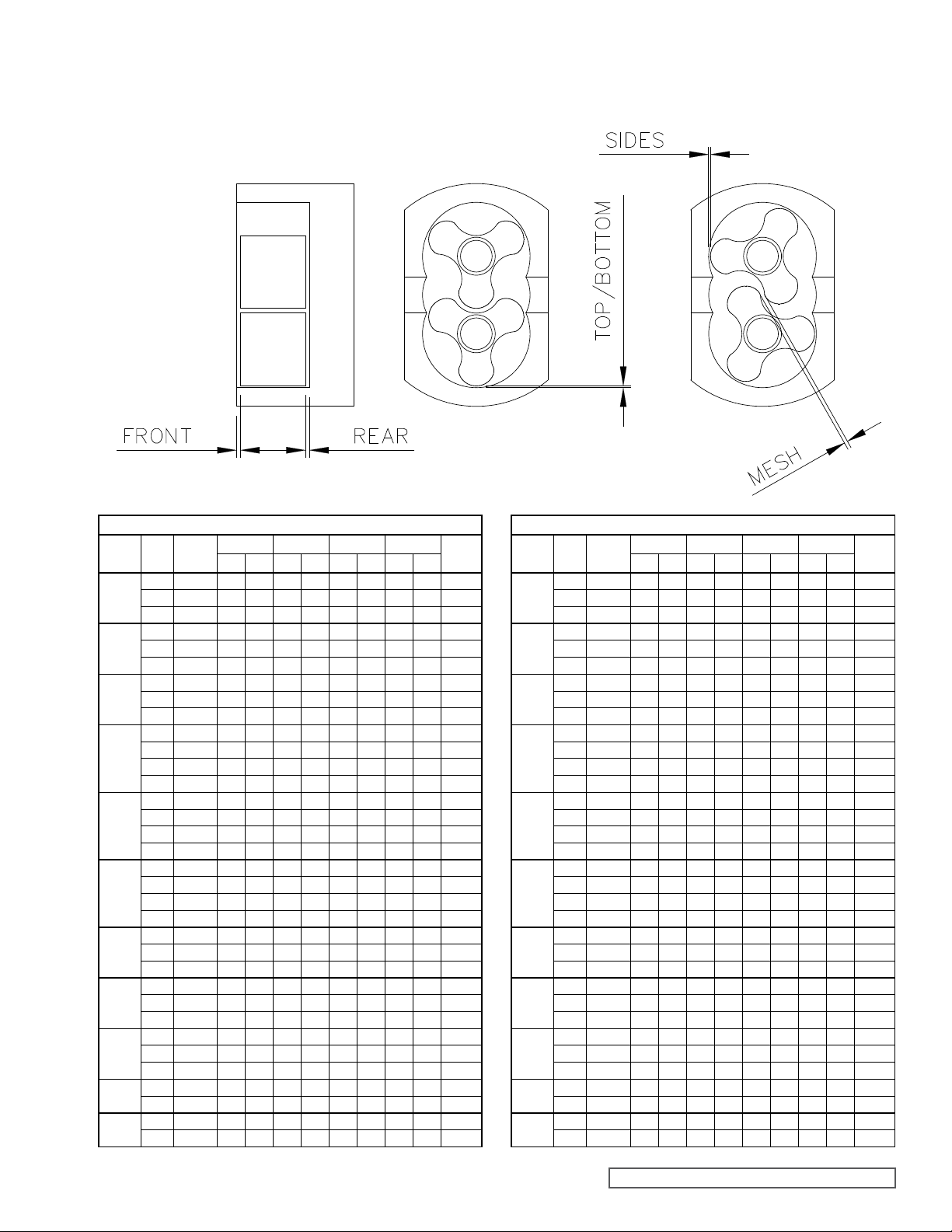
8.0 SPECIFICATIONS
8.1 CLEARANCE CHART
Pump
Model
CP10S
CP10M
CP10L
CP20S
CP20L
CP30S
CP30L
CP40S
CP40L
CP50S
CP50L
Millimeters x 0.01
Rotor
Max
Class
Temp °C
A 70 7 9 3 10 5 13 13 19 18
B 100 9 11 5 12 7 14 15 21 18
C 150 11 13 7 14 9 16 17 23 18
A 70 10 12 6 13 8 15 17 22 18
B 100 12 14 9 16 10 17 18 24 18
C 150 15 17 11 18 13 20 21 27 18
A 70 13 15 9 16 11 18 19 25 18
B 100 16 18 13 20 13 20 21 27 20
C 150 20 22 17 24 16 24 24 30 20
A 70 14 16 10 17 15 25 23 31 20
B 100 16 18 13 20 18 28 25 33 25
C 150 18 20 14 21 20 30 28 36 25
D 180 19 21 15 22 23 33 31 39 25
A 70 15 17 16 23 23 33 30 38 25
B 100 19 21 19 26 29 39 37 45 28
C 150 21 23 22 29 32 42 39 47 28
D 180 23 25 25 32 36 46 43 51 28
A 70 18 20 17 24 22 35 30 40 28
B 100 22 24 21 28 27 40 35 46 35
C 150 24 26 24 31 33 46 40 51 35
D 180 27 29 26 33 37 50 45 55 35
A 70 24 26 25 32 44 58 51 63 35
B 100 29 31 30 37 47 61 54 66 38
C 150 33 35 33 40 53 67 60 72 38
A 70 32 37 28 39 30 45 46 57 38
B 100 35 40 32 43 35 51 51 63 40
C 150 40 45 38 49 42 57 57 69 40
A 70 40 45 40 53 45 55 61 68 40
B 100 49 54 46 59 50 65 66 78 45
C 150 55 60 53 66 59 74 75 86 45
B 100 43 46 41 54 41 64 66 86 45
D 180 58 61 56 69 41 64 66 86 55
B 100 50 53 48 62 51 74 76 86 55
D 180 65 68 63 77 51 74 76 86 55
Front Rear Top/Bottom Side
Min Max Min Max Min Max Min Max
Nominal
Mesh
Pump
Model
CP10S
CP10M
CP10L
CP20S
CP20L
CP30S
CP30L
CP40S
CP40L
CP50S
CP50L
Inches x 0.001
Rotor
Max
Class
Temp °F
A 150 2.76 3.54 1.18 3.94 1.97 5.12 5.12 7.48 7.09
B 210 3.54 4.33 1.97 4.72 2.76 5.51 5.91 8.27 7.09
C 300 4.33 5.12 2.76 5.51 3.54 6.30 6.69 9.06 7.09
A 150 3.94 4.72 2.36 5.12 3.15 5.91 6.69 8.66 7.09
B 210 4.72 5.51 3.54 6.30 3.94 6.69 7.09 9.45 7.09
C 300 5.91 6.69 4.33 7.09 5.12 7.87 8.27 10.63 7.09
A 150 5.12 5.91 3.54 6.30 4.33 7.09 7.48 9.84 7.09
B 210 6.30 7.09 5.12 7.87 5.12 7.87 8.27 10.63 7.87
C 300 7.87 8.66 6.69 9.45 6.30 9.45 9.45 11.81 7.87
A 150 5.51 6.30 3.94 6.69 5.91 9.84 9.06 12.20 7.87
B 210 6.30 7.09 5.12 7.87 7.09 11.02 9.84 12.99 9.84
C 300 7.09 7.87 5.51 8.27 7.87 11.81 11.02 14.17 9.84
D 356 7.48 8.27 5.91 8.66 9.06 12.99 12.20 15.35 9.84
A 150 5.91 6.69 6.30 9.06 9.06 12.99 11.81 14.96 9.84
B 210 7.48 8.27 7.48 10.24 11.42 15.35 14.57 17.72 11.02
C 300 8.27 9.06 8.66 11.42 12.60 16.54 15.35 18.50 11.02
D 356 9.06 9.84 9.84 12.60 14.17 18.11 16.93 20.08 11.02
A 150 7.09 7.87 6.69 9.45 8.66 13.78 11.81 15.75 11.02
B 210 8.66 9.45 8.27 11.02 10.63 15.75 13.78 18.11 13.78
C 300 9.45 10.24 9.45 12.20 12.99 18.11 15.75 20.08 13.78
D 356 10.63 11.42 10.24 12.99 14.57 19.69 17.72 21.65 13.78
A 150 9.45 10.24 9.84 12.60 17.32 22.83 20.08 24.80 13.78
B 210 11.42 12.20 11.81 14.57 18.50 24.02 21.26 25.98 14.96
C 300 12.99 13.78 12.99 15.75 20.87 26.38 23.62 28.35 14.96
A 150 12.60 14.57 11.02 15.35 11.81 17.72 18.11 22.44 14.96
B 210 13.78 15.75 12.60 16.93 13.78 20.08 20.08 24.80 15.75
C 300 15.75 17.72 14.96 19.29 16.54 22.44 22.44 27.17 15.75
A 150 15.75 17.72 15.75 20.87 17.72 21.65 24.02 26.77 15.75
B 210 19.29 21.26 18.11 23.23 19.69 25.59 25.98 30.71 17.72
C 300 21.65 23.62 20.87 25.98 23.23 29.13 29.53 33.86 17.72
B 210 16.93 18.11 16.14 21.26 16.14 25.20 25.98 33.86 17.72
D 350 22.83 24.02 22.05 27.17 16.14 25.20 25.98 33.86 21.65
B 210 19.69 20.87 18.90 24.41 20.08 29.13 29.92 33.86 21.65
D 350 25.59 26.77 24.80 30.31 20.08 29.13 29.92 33.86 21.65
Front Rear Top/Bottom Side
Min Max Min Max Min Max Min Max
Nominal
Mesh
SECTION TSM 285 ISSUE A PAGE 31 OF 36
Page 32

8.2 FASTENERS & TORQUE
SETTINGS
Item Description Position
1.03 Dome Nut
2.02 Rotor Retainer Rotor / Shaft
2.05
3.03 Stud
4.02 Stud
4.04
5.01 Drive Shaft
5.02 Driven Shaft
5.07
5.07
5.12 Locknut
5.12 Grub Screw
5.14
5.16
5.19 Locknut Shaft / Bearing
6.11
6.11
6.15
7.11 Grub Screw
Ring Feder
Retainer
Socket Cap
Head Screw
Socket Cap
Head Screw
Hex Head
Screw
Socket Cap
Head Screw
Ring Feder
Retainer
Socket Cap
Head Screw
Socket Cap
Head Screw
Hammer
Drive Screw
Head /
Casing
Rotor / Shaft
Head /
Casing
Bearing Housing /
Head
Casing /
Bearing Housing
Bearing Housing /
Gearbox Housing
Bearing Housing /
Gearbox Housing
Bearing Retainer
Bearing Retainer
Timing Gear /
Shaft
Timing Gear /
Locknut
Feet
Timing Gear /
Shaft
Gearbox Halves
Rotor Cover /
Gearbox
Nameplate
Rotary Seal
Cartridge
Quantity / Pump 8 4 4 10 10
Size - mm M8 M12 M12 M16 M20
Torque Nm 28 101 101 115 150
Torque lbf ft 20.650 74.488 74.488 84.813 110.625
Quantity / Pump 2 2 2 2 2
Size - mm D13-2051-01 D23-2051-01 D33-2051-01 D43-2051-01 D53-2051-01
Torque Nm 27 30 40 60 50
Torque lbf ft 19.913 22.125 29.500 44.250 36.875
Quantity / Pump
Size - mm -
Torque Nm 15
Torque lbf ft
Quantity / Pump 4
Size - mm M8 x 31 M16 x 55 M16 x 70
Torque Nm 30 130 160
Torque lbf ft 22.125 95.875 118
Quantity / Pump 4 4 4
Size - mm M8 M12 M12
Torque Nm 30 107 107
Torque lbf ft 22.125 78.913 78.913
Quantity / Pump
Size - mm M6 M6
Torque Nm 16 16
Torque lbf ft 11.8 11.8
Rolling Torque Nm 0.4 - 0.6 1.2 - 1.5 4 - 5 5 - 6
Rolling Torque lbf ft 0.295-0.442 0.885 - 1.106 2.950-3.687 3.687 - 4.425
Rolling Torque Nm 0.4 - 0.6 1.2 - 1.5 4 - 5 5 - 6
Rolling Torque lbf ft 0.295-0.442 0.885 - 1.106 2.950-3.687 3.687 - 4.425
Quantity / Pump 8
Size - mm M6 x 16 M8 x 20 M8 x 25
Torque Nm 16 29 29
Torque lbf ft 11.800 21.388 21.388
Quantity / Pump
Size - mm M5 x 16 M5 x 16
Torque Nm 9.5 9.5
Torque lbf ft 7.006 7.006
Quantity / Pump 2 2 2 1 1
Size - mm M25 M30 D33-0141-04 M55 M65
Torque Nm 25 35 55 50 50
Torque lbf ft 25.813 40.563
Quantity / Pump
Size - mm M8 x 8
Torque Nm 20
Torque lbf ft 14.750
Quantity / Pump 2 4 4 4 4
Size - mm M8 x 16 M8 x 16 M10 x 25 M12 x 30 M16 x 40
Torque Nm 39 39 45 80 180
Torque lbf ft 28.763 33.188
Quantity / Pump
Size - mm - -
Torque Nm 34 34
Torque lbf ft
Quantity / Pump
Size - mm M60 M80
Torque Nm 50 60
Torque lbf ft 36.875 44.250
Quantity / Pump 4 4 6
Size - mm M8 x 20 M10 x 25 M12 x 25
Torque Nm 39 57 100
Torque lbf ft 42.038 73.750
Quantity / Pump
Size - mm M10 x 30 M12 x 25
Torque Nm 60 70
Torque lbf ft
Quantity / Pump 4 4 4 4 4
Size - mm
Torque Nm
Torque lbf ft
Quantity / Pump 6 or 8 6 or 8 6 or 8 6
Size - mm M5 M5 M6 M8
Torque Nm 1.5 1.5 4 9.5
Torque lbf ft 1.106 2.950
CP10 CP20 CP30 CP40 CP50
N/A N/A N/A N/A
N/A N/A
2 2
N/A
N/A N/A
8 8
N/A
N/A N/A
N/A N/A N/A
N/A N/A N/A
N/A N/A N/A
Pump Model
6 6
N/A N/A
N/A N/A
8 8
N/A N/A
6
N/A N/A
1 1
2 2
N/A N/A
4 4
2
N/A
N/A
N/A
SECTION TSM 285 ISSUE A PAGE 32 OF 36
Page 33
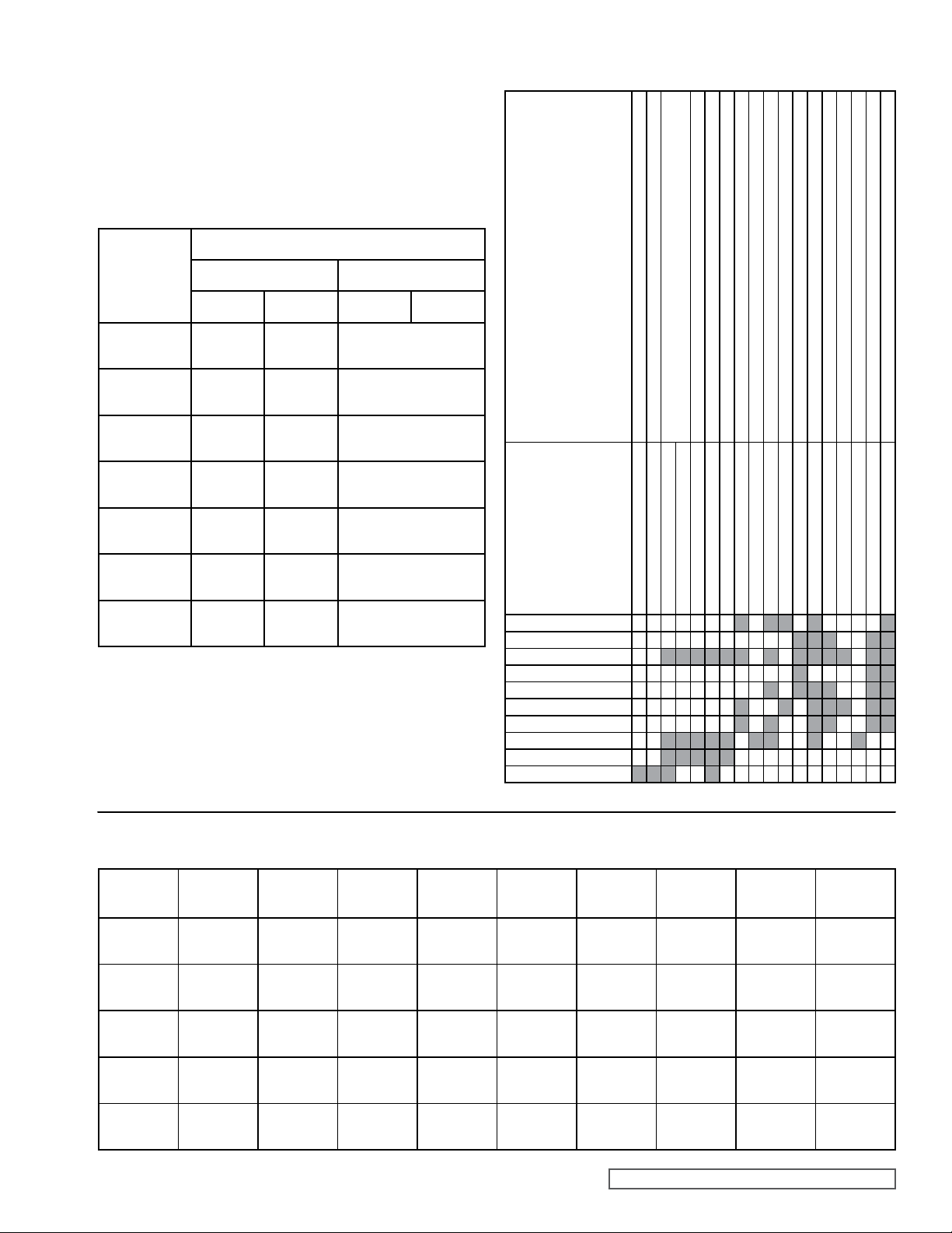
8.3 LUBRICANTS
Gearbox oil recommended for use with Classic+ is an
‘EP (Extreme Pressure) grade gear lube’ for the following
temperature ranges.
EP150 -2 – 0°C (0 – 32°F)
EP220 0 – 30°C (32 - 85°F)
EP320 30°C (85°F) and higher
ApproximatelubricantcapacitiesfortheClassic+:
Mounting Attitude with Suction and Discharge ports in:
8.4 TROUBLESHOOTING
Pump Model
Horizontal Plane Vertical Plane
Liters US Pints Liters US Pints
CP10 0.25 0.44
CP20 0.50 0.88
CP30 1.00 1.76
CP40*
(Top Cavity)
CP40*
(Bottom Cavity)
CP50*
(Top Cavity)
CP50*
(Bottom Cavity)
0.75 1.32
1.75 3.08
0.60 1.05
0.80 1.41
To be advised - Fill to Sight
Glass level (see below)
To be advised - Fill to Sight
Glass level (see below)
To be advised - Fill to Sight
Glass level (see below)
To be advised - Fill to Sight
Glass level (see below)
To be advised - Fill to Sight
Glass level (see below)
To be advised - Fill to Sight
Glass level (see below)
To be advised - Fill to Sight
Glass level (see below)
* Note: The CP40 and CP50 have two gearbox cavities that
should be subject to the same maintenance program.
Always add oil to the level of the sight glass. The sight glass
must be located in the uppermost position on the side of the
gearbox.
Causes Action
Reduce Length. Reduce Pump Speed & Product Temperature
Incorrect Direction of Rotation Reverse Motor
Pump Not Primed Expel Gas From Suction Line / Pump Chamber & Prime
Insufficient NPSH Available Increase Line Diameter & Static Suction Head. Simplify Suction Line &
Product Vaporizing in Suction Line
Air Entering Suction Line Remake Piping Joints
Gas in Suction Line Expel Gas From Suction Line / Pump Chamber
Insufficient Static Suction Head Raise Product Level to Increase Static Suction Head
Product Viscosity Too High Decrease Pump Speed / Increase Product Temperature
Product Viscosity Too Low Increase Pump Speed / Decrease Product Temperature
Product Temperature Too High Cool Product / Pumping Chamber
Product Temperature Too Low Heat Product / Pumping Chamber
Unexpected Solids in Product Clean the System / Fit Strainer on Suction Side of Pump
Discharge Pressure Too High Check for Blockages / Simplify Discharge Line
Casing Strained by Piping Check Pipe Alignment / Support Piping
Pump Speed Too High Decrease Pump Speed
Pump Speed Too Low Increase Pump Speed
Seal Flush Inadequate Increase Seal Flush to Required Pressure / Flow
Pump Stalls on Startup
Seizure
Noise / Vibration
Excessive Seal Wear
Excessive Rotor Wear
Motor Overheats
Pump Overheats
Under Capacity
Irregular Flow
No Flow
Bearing / Timing Gear Wear Replace Worn Components
8.5 MATERIAL SPECIFICATIONS
Pump
Model Casing
CP10
CP20
CP30
CP40
CP50
316
Stainless Steel
316
Stainless Steel
316
Stainless Steel
316
Stainless Steel
316
Stainless Steel
Front
Cover Rotors
316
Stainless Steel
316
Stainless Steel
316
Stainless Steel
316
Stainless Steel
316
Stainless Steel
316
Stainless Steel
316
Stainless Steel
316
Stainless Steel
316
Stainless Steel
316
Stainless Steel
Retainers Shafts
Stainless Steel
Stainless Steel
Stainless Steel
Stainless Steel
Stainless Steel
Rotor
316
316
316
316
316
316
Stainless Steel
316
Stainless Steel
316
Stainless Steel
316
Stainless Steel
316
Stainless Steel
Shaft
Sleeves Gearbox
N/A
N/A
N/A
N/A
316
Stainless Steel
SECTION TSM 285 ISSUE A PAGE 33 OF 36
Cast Iron Cast Iron
Cast Iron Cast Iron
Cast Iron Cast Iron
Cast Iron
Cast Iron
Bearing
Housing
N/A Mild Steel
N/A Mild Steel
Gearbox
Cover
N/A
N/A
N/A
Page 34
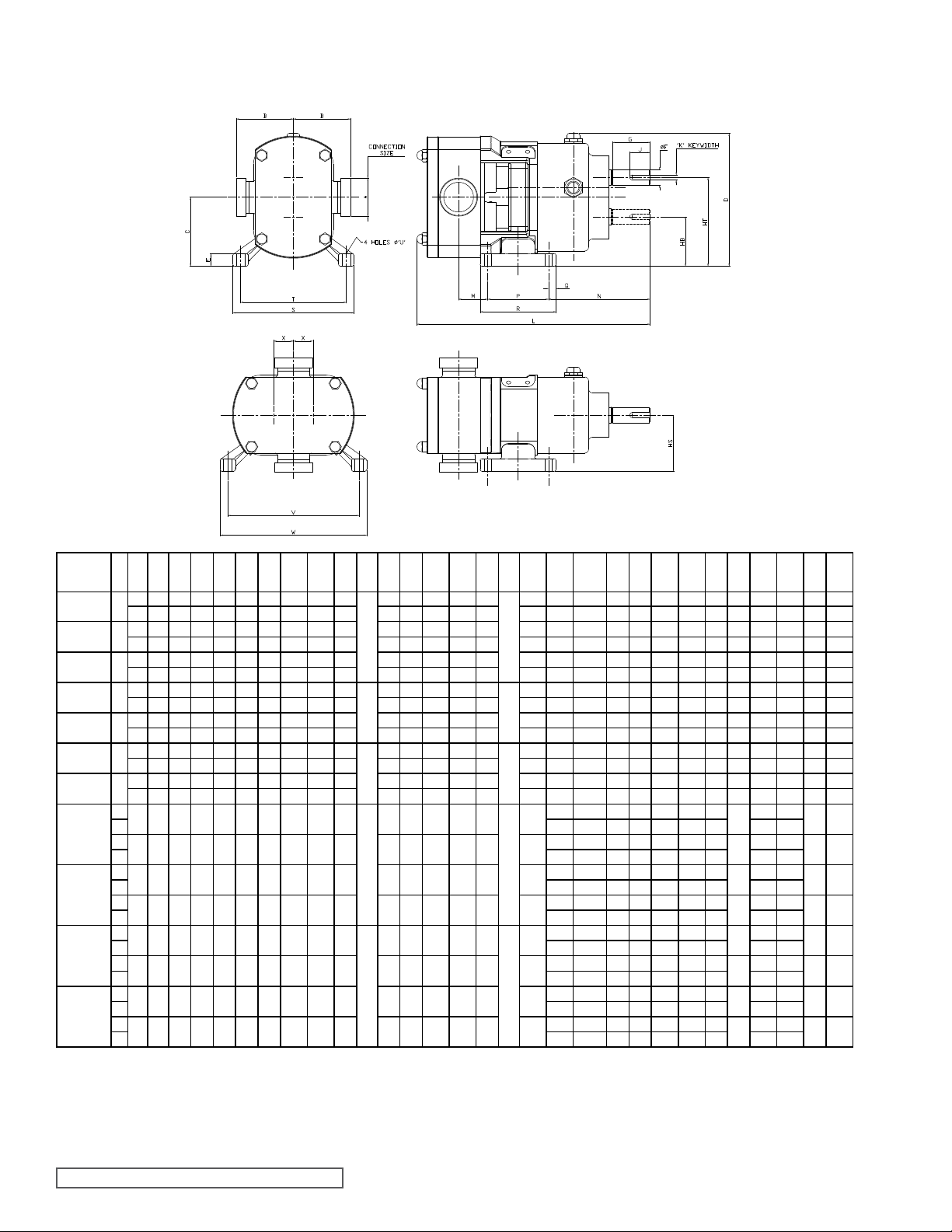
8.6 FOUNDATION DIMENSIONS
AND WEIGHTS
MODEL
CP10S
CP10M
CP10L
CP20S
CP20L
CP30S
CP30L
CP40S
CP40L
CP50S
CP50L
① ②
H
V
H
V
H
V
H
V
H
V
H
V
H
V
H
V 5.16 9.08 7.24 0.71 8.66 - - - - - - 8.98 10.75
H
V 131 230.75 184 18 220 - - - - - - 228 273
H
V 5.89 9.08 7.24 0.71 8.66 - - - - - - 8.98 10.75
H
V 149.5 230.75 184 18 220 - - - - - - 228 273
H
V 6.61 9.49 9.37 0.79 10.94 - - - - - - 9.84 11.81
H
V 168 241 238 20 278 - - - - - - 250 300
H
V 7.72 9.49 9.37 0.79 10.94 - - - - - - 9.84 11.81
H
V 196 241 238 20 278 - - - - - - 250 300
⑤B1⑤B2⑤B3⑤B4⑤
A
in 1 3.5 3.5 4.06 4.06 4.06 2.91 6.18 0.39181.10
mm 25 89 89 103 103 103 74 157 10 28
in 1.5 3.5 4.37 4.06 4.06 4.06 2.91 6.18 0.39 1.10
mm 40 89 111 103 103 103 74 157 10 28
in 1.5 3.5 4.37 4.06 4.06 4.06 2.91 6.18 0.39 1.10 1.89
mm 40 89 111 103 103 103 74 157 10 28 48
in
3.86 4.72 4.41 4.41 4.41 4.29 8.62 0.79242.32 3.07
1.5
mm 40 98 120 112 112 112 109 219 20 59 78
in 2 3.86 4.72 4.41 4.41 4.72 4.29 8.62 0.79 2.32 3.07
mm5098 120 112 112 120 109 219 20 59 78
in 2 4.88 5.75 5.43 5.43 5.75 5.26 10.71 0.98382.74 3.43
mm50124 146 138 138 146 133.5 272 25 69.5 87
in 3 4.88 6.14 5.43 5.75 5.95 5.26 10.71 0.98 2.74 3.43
mm80124 156 138 146 151 133.5 272 25 69.5 87
in 3 6.26 7.52 6.81 7.13 7.32 6.97 13.50 0.91484.33 4.49
mm 80 159 191 173 181 186 177 343 23 110 114
in 4 6.42 8.11 6.81 7.13 7.32 6.97 13.50 0.91 4.33 4.49
mm 100 163 206 173 181 186 177 343 23 110 114
in 4 7.4 9.25 7.95 8.27 8.47 8.46 16.61 1.18604.09 5.32
mm 100 188 235 202 210 215 215 422 30 104 135
③
in
N/A N/A 7.17 7.17 N/A 8.46 16.61 1.18 4.09 5.32
6
③
mm
N/A N/A 182 182 N/A 215 422 30 104 135
150
B5
C D E
④
F
G HB HS HT J
mm
1.89 2.48 3.94
48 63 100
1.89 2.48 3.94
48 63 100
2.48 3.94
63 100
3.49 5.51
88.75 140
3.49 5.51
88.75 140
4.38 7.09
111.3 180
4.38 7.09
111.3 180
6.89 9.45
175 240
6.89 9.45
175 240
8.07 11.61
205 295
8.07 11.61
205 295
④
K
L M N P Q
mm
0.9869.80 1.87 4.58 1.77 0.39
25 249 47.5 116.40 45 10
0.98 10.39 2.15 4.58 1.77 0.39
25 264 54.5 116.40 45 10
0.98 10.87 2.58 4.58 1.77 0.39
25 276 65.5 116.40 45 10
1.26813.74 1.38 6.32 3.78 0.47
32 349 35 160.50 96 12
1.26 14.53 1.81 6.32 3.78 0.47
32 369 46 160.50 96 12
1.571017.44 2.39 7.74 4.53 0.59
40 443 60.6 196.50 115 15
1.57 18.82 3.17 7.74 4.53 0.59
40 478 80.6 196.50 115 15
3.541425.47
90 647
3.54 26.73
90 679
2.321829.72
59 755
2.32 32.09
59 815
6.42 10.35 4.72 0.89
163 262.80 120 22.5
7.14 10.35 4.72 0.89
181.3 262.80 120 22.5
8.35 11.22 5.91 0.98
212 285 150 25
9.45 11.22 5.91 0.98
240 285 150 25
R
S T U V W
2.56
5.75 4.96 0.33 6.40
65
146 126 8.50 162.5
2.56
5.75 4.96 0.33 6.40
65
146 126 8.50 162.5
2.56
5.75 4.96 0.33 6.40
65
146 126 8.50 162.5
4.72
7.68 6.57 0.43 8.17
120
195 167 11 207.5
4.72
7.68 6.57 0.43 8.17
120
195 167 11 207.5
5.71
10.16 8.98 0.51 10.72
145
258 228 13 272.3
5.71
10.16 8.98 0.51 10.72
145
258 228 13 272.3
6.50
8.66 7.24
165
220 184
6.50
8.66 7.24
165
220 184
7.87
10.24 8.66
200
260 220
7.87
10.24 8.66
200
260 220
0.71
18
0.71
18
0.79
20
0.79
20
7.20 1.02 28.6
183 26 13
7.20 1.02 30.8
183 26 14
7.20 1.02 33.0
183 26 15
9.27 1.22 61.6
235.5 31 28
9.27 1.22 68.2
235.5 31 31
11.90 1.83 156.2
302.3 46.5 71
11.90 1.83 169.4
302.3 46.5 77
- - -
- - -
- - -
- - -
- - -
- - -
- - -
- - -
- - -
- - -
- - -
- - -
- - -
- - -
- - -
- - -
Wt.
X
Lb
Kg
2.48 330.0
63 150
2.48 356.4
63 162
3.15 554.4
80 252
3.15 602.8
80 274
① H= Horizontal Mounting V=Vertical mounting
② Pumps standard with external NPT ports, except where noted otherwise.
③
Ports are suitable for use with 150# ANSI stainless steel companion
flanges or flanged fittings.
④ Metric shaft coupling and key required.
SECTION TSM 285 ISSUE A PAGE 34 OF 36
⑤
B1 applies for all threaded connections except BSPT or NPT
B2 applies for BSPT and NPT threaded connections
B3 applies for all flange connections except ASA150, BS4504 & ASA300
B4 applies for ASA150 and BS4504 ange connections
B5 applies for ASA300 ange connections
Page 35
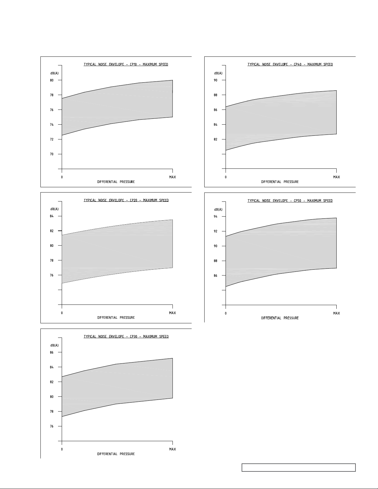
8.7 TYPICAL NOISE EMISSION
DATA - CP10, CP20 AND CP30
PUMPS
8.8 TYPICAL NOISE EMISSION
DATA - CP40 AND CP50 PUMPS
SECTION TSM 285 ISSUE A PAGE 35 OF 36
Page 36
TECHNICAL SERVICE MANUAL
SECTION TSM 285
CLASSIC+ SERIES ROTARY LOBE PUMPS
MODELS CP10, CP20, CP30, CP40 & CP50
WARRANTY
Viking warrants all products manufactured by it to
be free from defects in workmanship or material for a
period of one (1) year from date of startup, provided
that in no event shall this warranty extend more than
eighteen (18) months from the date of shipment from
Viking. If, during said warranty period, any products
sold by Viking prove to be defective in workmanship
or material under normal use and service, and if such
products are returned to Viking’s factory at Cedar Falls,
Iowa, transportation charges prepaid, and if the products
are found by Viking to be defective in workmanship
or material, they will be replaced or repaired free of
charge, FOB. Cedar Falls, Iowa.
Viking assumes no liability for consequential
damages of any kind and the purchaser by acceptance
of delivery assumes all liability for the consequences of
the use or misuse of Viking products by the purchaser,
his employees or others. Viking will assume no field
expense for service or parts unless authorized by it in
advance.
Equipment and accessories purchased by Viking
from outside sources which are incorporated into any
Viking product are warranted only to the extent of and
by the original manufacturer’s warranty or guarantee,
if any.
THIS IS VIKING’S SOLE WARRANTY AND IS IN
LIEU OF ALL OTHER WARRANTIES, EXPRESSED
OR IMPLIED, WHICH ARE HEREBY EXCLUDED,
INCLUDING IN PARTICULAR ALL WARRANTIES
OF MERCHANTABILITY OR FITNESS FOR A
PARTICULAR PURPOSE. No officer or employee of
IDEX Corporation or Viking Pump, Inc. is authorized to
alter this warranty.
PAGE 36 OF 36
ISSUE A
VIKING PUMP, INC. • A Unit of IDEX Corporation • Cedar Falls, IA 50613 USA
©9/2007 Viking Pump Inc.
All rights reserved
 Loading...