

Page 1
Electronic copies of the most current TSM issue can be found on the Viking Pump website at www.vikingpump.com
TECHNICAL SERVICE MANUAL
IN-LINE BASKET-TYPE STRAINERS
CONTENTS
Introduction.....................................................................1
Contents.........................................................................1
Special Information.........................................................1
Installation.......................................................................2
Disassembly....................................................................2
Assembly.........................................................................2
Assembly (Cont.).........................................................3
O-ring Information...........................................................3
Warranty.........................................................................4
INTRODUCTION
This bulletin deals exclusively with Viking Lid-Ease®
Basket-Type Strainers. When ordering parts be sure to give
complete part name, serial number and model number (cast
on body below serialized nameplate). The basket mesh size
is stamped on the basket handle and the o-ring construction
can be identified with a Viking color code (listed under O-Ring
Information).
Use of basket strainers can avoid costly failures and increase
the life of the equipment. Proper use of strainer can minimize
down time. A definition for strainers is “a coarse filter”.
Strainers are typically intended to trap larger foreign objects
SECTION TSM
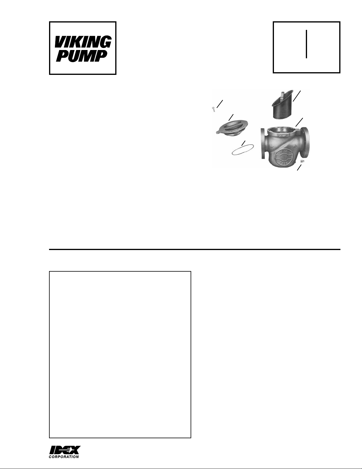
LID-EASE® SIMPLEX
THUMBSCREW
LID
O-RING
FIGURE 1
such as rags, weld beads or bolts. Filters are intended to
capture very small particles.
Lid sealing is accomplished with one o-ring, therefore
proper application of o-ring is essential. The o-ring must be
acceptable for the temperature limits of the system as well
as compatible with the fluid being strained. Misapplication
may result in o-ring swell, (making lid removal difficult) or
premature o-ring failure, causing strainer leakage.
PAGE
ISSUE
STRAINER
BASKET
STRAINER
BODY
PLUG
640
1
E
SPECIAL INFORMATION
DANGER !
Before opening any Viking product (Strainer,
pumping chamber, reservoir, relief valve
adjusting screw cap etc.) be sure:
1. That any pressure in the strainer or pumping
chamber has been completely vented
through suction or discharge lines or other
appropriate openings or connections.
2. That the driving means (motor, turbine,
engine, etc.) has been “Locked Out” or
made non-operational so that it cannot
be started while maintenance is being
preformed.
3. That you know what liquid the strainer
has been handling and the necessary
precautions to safely handle the liquid.
Obtain a Material Safety Data Sheet (MSDS)
for the liquid to be sure these precautions
are understood.
Failure to follow above listed precautionary
measures may result in serious injury or
death.
Viking does not recommend using Lid-Ease Strainers for the
following applications:
1. Fluids having vapor pressure higher than one atmosphere,
either at room temperature or operating temperature.
2. Straining of particles finer than 70 microns (50Х250 Mesh
available through 4”).
3. Temperatures below -40 ºF or above +400 ºF.
4. High system pressure applications (See Table A, Page 2).
5. High basket differential pressure (See Table A).
6. Aluminium strainer handling 1,1,1-trichloroethane,
methylene chloride or halogenated hydrocarbon solvents.
Determine and exercise necessary precautions before
removing the lid, involving fluids which are:
- POISONOUS OR TOXIC
- FLAMMABLE
- HARMFUL TO FACE OR HANDS
- HOT (Liquids containing boiling water (+212º F at sea
level) can produce steam; extra care to properly vent
strainer must be exercised).
- ENTRAINED WITH AIR (Trapped, pressurized air under
lid can lift the lid suddenly and violently if the lid is rotated.
Be the sure system is completely vented)
DO NOT ATTEMPT TO VENT THE SYSTEM BY TURNING
THE LID.
VIKING PUMP, INC. • A Unit of IDEX Corporation • Cedar Falls, IA 50613 USAVIKING PUMP, INC. • A Unit of IDEX Corporation • Cedar Falls, IA 50613 USA
Page 2

Strainer Size
Basket Clearance
(Required from
port centerline)
Maximum Basket
Differential
Pressure (PSID)
Maximum System
Pressure (PSIG)
①
175 PSI on liquid temperature below 150 °F
1” 1 1/2” 2” 3” 4” 6” 8”
6.0 6.5 7.5 9.5 11.75 16.5 24.5
150 150 150 125 125 75 50
200 200 200
TABLE A
①
125 ①125 ①125 ①125
INSTALLATION
Strainers should be placed ahead of any equipment needing
protection. The mesh size used in the strainer body should be
only as small as required to protect the equipment. This will
minimize the pressure drop through the strainer. For pump
protection locate the strainer on suction side of the pump.
Proper sizing of the strainer and basket mesh can prevent
the pump from cavitating due to excessive pressure drop
across the strainer. There are several factors which influence
pressure drop such as viscosity of fluid, percentage and size
of particles or contaminants, and frequency of cleaning.
If the liquid contains undesirable ferrous particles, magnetic
inserts can be added to the baskets to help remove these
particles.
A second strainer (or filter) located on discharge side of pump
may be desirable to protect other equipment in the system
which requires a smaller mesh basket for finer straining of
the liquid. A basket with a smaller mesh opening (the higher
the mesh number, the smaller the opening in the mesh) can
be permitted on the discharge side because pressure drop is
less critical. Maximum differential pressures allowable across
strainers are listed in Table A.
Locate the strainer in a position where the drain plug can
be easily removed (Replace the plug with a drain valve for
frequent maintenance). Provide adequate space above the
strainer for basket removal as listed in table A. The Lid-Ease
strainer has cast arrows on the body to indicate the direction
fluid must flow. These strainers are not designed for any type
of backwash operation.
NOTE: Mounting the strainer with ports in a vertical position
is NOT recommended because of increased difficulty during
servicing.
For the larger strainers, additional external support of the
strainer may be required to reduce pipe strain in the system.
This can be accomplished either by supporting the flanges or
providing a base for the bottom of the strainer. Lid removal for
maintenance will be much easier if the top of the strainer is
not over 3 feet off the ground. In the event that the strainer is
not at highest point in the system, valves are recommended
on both sides of strainer to prevent the strainer from filling up
while cleaning the basket.
As the basket becomes clogged with foreign matter,
differential pressure will rise. Table A shows maximum
pressure differential allowable across the basket. If this
pressure is exceeded, damage to the basket may occur. A
good way to indicate when basket must be cleaned is to: 1)
Install a pressure differential gauge or 2) install a pressure
gauge on each side of the strainer.
NOTE: Strainers located on the discharge side of the pump
must have a safety relief valve between the pump and the
strainer set no higher than the strainer’s maximum system
pressure (see Table A).
DISASSEMBLY
NOTE: Before removing the lid to clean the basket make
sure that you have a spare o-ring in the event that the fluid
being strained has caused the o-ring to swell.
DANGER !
Before opening any Viking product (Strainer,
pumping chamber, reservoir, relief valve
adjusting screw cap etc.) be sure:
1. That any pressure in the strainer or pumping
chamber has been completely vented through
suction or discharge lines or other appropriate
openings or connections.
2. That the driving means (motor, turbine,
engine, etc.) has been “Locked Out” or made
non-operational so that it cannot be started
while maintenance is being preformed.
3. That you know what liquid the strainer has
been handling and the necessary precautions
to safely handle the liquid. Obtain a Material
Safety Data Sheet (MSDS) for the liquid to be
sure these precautions are understood.
Failure to follow above listed precautionary
measures may result in serious injury or
death.
1. Remove the thumbscrew from top of lid.
2. Rotate the weatherseal lid counter clockwise until the pin
hits and stops. (The lid features an internal pin, which
locates the on and off positions.)
3. Raise up the lid.
4. Remove the basket and clean. Do not strike the basket
to clean it out; this could deform the basket side or lip
and decrease the strainers effectiveness. Avoid using a
sharp object such as a screwdriver, which could puncture
the mesh. To clean the basket, use a small brush or
compressed air.
ASSEMBLY
1. Place basket into strainer body.
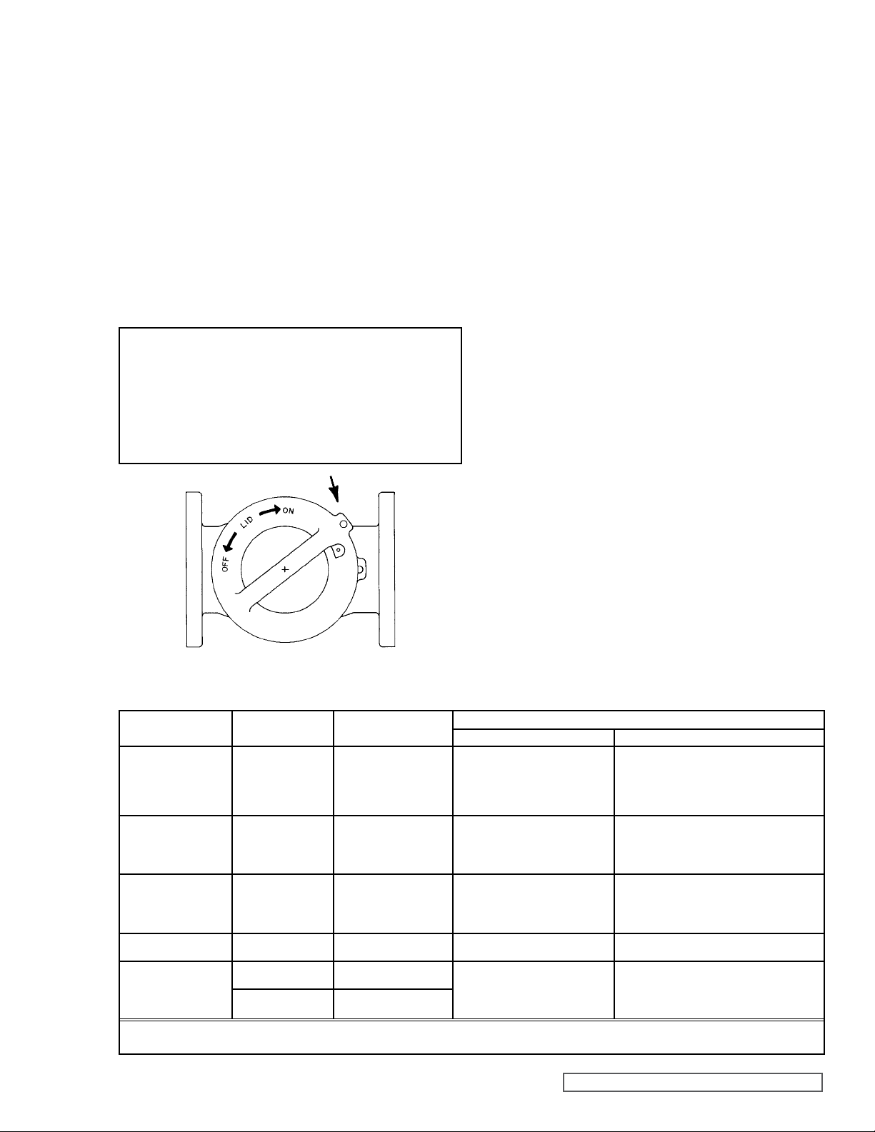
2. Reinstall the lid with the tab of the lid just to the left of the
boss with the threaded hole on the body (See fig. 2).
NOTE: Do not attempt to install the lid if the strainer has
filled up; drain before installing the lid. Press down on
the lid firmly and evenly until it pops into place.
SECTION TSM 640 ISSUE F PAGE 2 OF 4
Page 3
ASSEMBLY (Cont.)
3. Rotate the lid clockwise until the two holes line up.
4. Reinsert the thumbscrew.
5. Reinstall the drain plug (if removed) or close the drain
valve (if installed).
6. Before starting up the system, make sure to open all
valves that were closed for servicing. After starting up
the system, check for any possible leaks. If there is any
leakage around the lid, return to Disassembly. Remove
the lid and refer to Trouble-Shooting, page 4, for possible
causes of leakage.
NOTE: When installing a new o-ring, it is recommended that
the o-ring be lubricated with grease before installing onto
the lid.
DANGER !
Before starting the system, be sure the lid
is turned to the proper position and the
thumbscrew is installed to prevent the lid
from turning
O-RING INFORMATION
Proper application and use of the o-ring elastomer will affect
the ease of lid removal and the life of the o-ring. Compatibility
of the elastomer with the fluid(s) at operating temperature
extremes, is essential and Table B lists suitability for several
o-ring elastomers, along with Viking’s means of identification.
If an o-ring is incompatible with a fluid, excessive o-ring swell
or contraction might result and/or properties of the elastomer
may change, reducing the satisfactory performance life of
the o-ring. Included in Table B is a general list of fluids that
Parker’s O-Ring Manual does and does not recommend
for specific elastomers. Obviously if an o-ring should swell,
sealing will be enhanced between lid and body, but would
make the lid difficult to remove. Conversely, o-ring shrinkage
will reduce sealing and possibly cause a leak. Several good
sources are available covering o-ring compatibility. These
include o-ring manufacturers literature, Viking Pump’s Liquid
List, Viking’s Application Department, manufacturers of other
components in the system and previous experience.
Generally it is best to have an extra o-ring on hand when
removing the lid. Once the lid has been removed, if any
swelling has occurred, reinstalling the lid with the existing
o-ring will be difficult (if not impossible) and may require
another o-ring. Once o-ring dries out, it can sometimes be
used again.
PTFE (Derivative) Encapsulated o-rings generally do not
swell. Do not attempt to reuse this type of o-ring if it has been
removed. Immerse a new o-ring in boiling water for a few
minutes. Remove from the water and stretch out the o-ring so
it will fit onto the casing hub of the lid without forcing it over
a sharp edge. Run hot water over the o-ring until it shrinks
down tight into the groove of lid.
FIGURE 2
TABLE B
O-RING SELECTION
TYPE OF ELASTOMER
BUNA NO DOT -20 TO +225 Petroleum, oils and fluids
VITON GREEN DOT -15 TO +400 Petroleum oils
ETHYLENE PROPYLENE
RUBBER
SANITARY YELLOW DOT -20 TO +225 Same as Buna-N
PTFE (DERIVATIVE)
ENCAPSULATED
VIKING
IDENTIFICATION
ORANGE DOT -65 TO +300 Water
NO DOT ORANGE
CORE
NO DOT
PURPLE CORE
① Temperatures listed are for static seal applications only for the Lid-Ease Simplex strainer line.
② Source: Parker O-Ring Handbook (except for PTFE (Derivative) Encapsulated).
TEMPERATURE LIMIT ①
LIMIT °F
(STANDARD)
-40 TO +300
(HIGH TEMP)
-40 TO +400
RECOMMENDED NOT RECOMMENDED
Silicone greases & oils
Ethylene glycol base
General purpose sealing
Di-Ester base lubricant
Silicone fluids & grease
Halogenated hydrocarbon
Selected phosphate ester acids
Dilute Acids
Dilute alkalies
Ketones
Alcohol
Most solvents & chemicals
Consult factory if unsure about
compatibility
LIQUIDS ②
Halogenated hydrocarbon
Nitro hydrocarbon
Phosphate ester
Ketones
Ozone
Automotive break fluid
Ketones
Skydrol
Amines
Low molecular weight esters & ethers
Hot hydrofluoric or chlorosulfonic acids
Petroleum Oil
Di-Ester base lubricant
Molten alkali metals
Fluorine and strong
fluorinating agents
SECTION TSM 640 ISSUE F PAGE 3 OF 4
Page 4
TECHNICAL SERVICE MANUAL
TROUBLESHOOTING
PROBLEM POSSIBLE CAUSE SOLUTIONS
The Lid is difficult
to turn
The lid is difficult to
install
Fluid leaks around
the top of the strainer
There is excessive
pressure drop
1) The system is under pressure 1) Relieve the pressure
2) The o-ring is swollen 2) Check compatibility of the o-ring with the fluid and temperature.
3) The fluid inside is sticky or solid 3) a) Remove the lid before liquid solidifies
b) May require heat tape and insulation around body
4) The o-ring is swollen 4) Replace with a new o-ring, or a different, more compatible o-ring material
5) The o-ring is not lubricated 5) Lubricate the o-ring with grease or a suitable lubricant
6) There is too much fluid in the body 6) Drain out the fluid, leaving more air in the body before installing the lid
7) The o-ring is cut 7) Replace the o-ring (never try to install a cut o-ring)
8) There is foreign material under the o-ring 8) Remove & clean the o-ring, groove in lid, & body o-ring seat.
Reinstall, making sure to lubricate the o-ring
9) The o-ring has shrunk 9) Select a compatible o-ring material
10) The basket is filled with contaminants 10) Clean the basket more frequently
11) The basket mesh is too fine 11) Check the pressure drop curves. A larger strainer or a larger mesh
basket may be required
12) The viscosity is too high 12) Increase the strainer unit size or use a larger mesh basket.
SECTION TSM 640
PAGE 4
ISSUE F
WARRANTY
Viking warrants all products manufactured by it to be free from defects in workmanship or material for a period of one (1)
year from date of startup, provided that in no event shall this warranty extend more than eighteen (18) months from the
date of shipment from Viking. The warranty period for Universal Seal series pumps ONLY (Universal Seal models listed
below) is three (3) years from date of startup, provided that in no event shall this warranty extend more than forty-two
(42) months from the date of shipment from Viking.
UNDER NO CIRCUMSTANCES SHALL VIKING BE LIABLE UNDER THIS WARRANTY OR OTHERWISE FOR
SPECIAL, INCIDENTAL, INDIRECT, CONSEQUENTIAL OR PUNITIVE DAMAGES OF ANY KIND, INCLUDING,
BUT NOT LIMITED TO, LOST OR UNREALIZED SALES, REVENUES, PROFITS, INCOME, COST SAVINGS OR
BUSINESS, LOST OR UNREALIZED CONTRACTS, LOSS OF GOODWILL, DAMAGE TO REPUTATION, LOSS OF
PROPERTY, LOSS OF INFORMATION OR DATA, LOSS OF PRODUCTION, DOWNTIME, OR INCREASED COSTS,
IN CONNECTION WITH ANY PRODUCT, EVEN IF VIKING HAS BEEN ADVISED OR PLACED ON NOTICE OF THE
POSSIBILITY OF SUCH DAMAGES AND NOTWITHSTANDING THE FAILURE OF ANY ESSENTIAL PURPOSE OF
ANY PRODUCT.
THIS WARRANTY IS AND SHALL BE VIKING’S SOLE AND EXCLUSIVE WARRANTY AND SHALL BE IN LIEU OF
ALL OTHER WARRANTIES, EXPRESS OR IMPLIED, INCLUDING, BUT NOT LIMITED TO, ALL WARRANTIES OF
MERCHANTABILITY, FITNESS FOR A PARTICULAR PURPOSE AND NON-INFRINGEMENT ALL OF WHICH OTHER
WARRANTIES ARE EXPRESSLY EXCLUDED.
See complete warranty at www.vikingpump.com.
VIKING PUMP, INC. • A Unit of IDEX Corporation • Cedar Falls, IA 50613 USA
© 3/2013 Viking Pump Inc.
All rights reserved
 Loading...