

Page 1
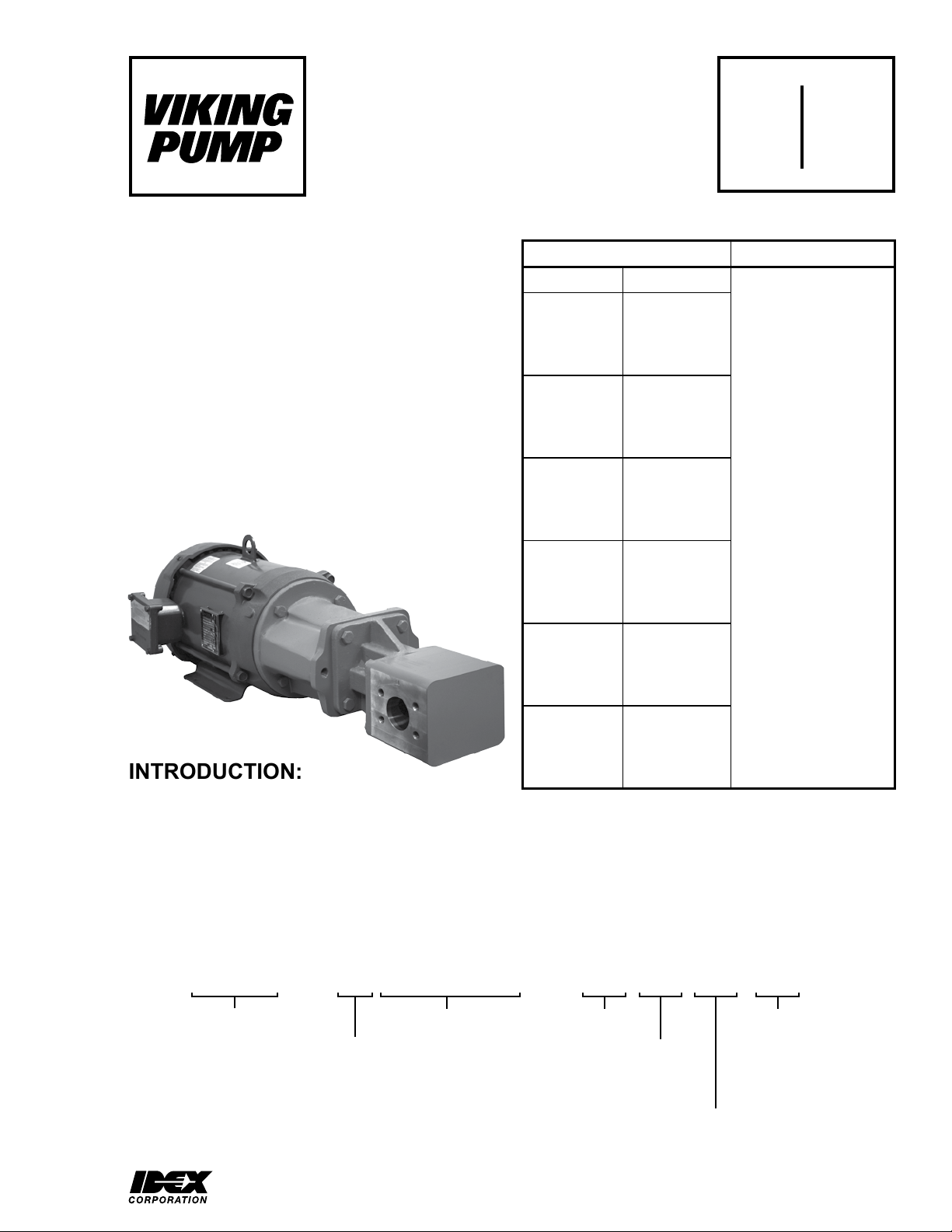
Electronic copies of the most current TSM issue can be found on the Viking Pump website at www.vikingpump.com
TECHNICAL SERVICE MANUAL
EXTERNAL GEAR PUMPS
SERIES SG-10, -14
SECTION TSM 340.1
PAGE 1 Of 11
ISSUE D
CONTENTS: MODEL NUMBER CHART:
Introduction . . . . . . . . . . . . . . . . . . . . . . . . 1
Model Number System . . . . . . . . . . . . . . . . . . 1
Safety Information. . . . . . . . . . . . . . . . . . . . .2
Special Information . . . . . . . . . . . . . . . . . . . . 3
Installation. . . . . . . . . . . . . . . . . . . . . . . . .3
Maintenance . . . . . . . . . . . . . . . . . . . . . . . 4
Lip Seal Pumps - Disassembly . . . . . . . . . . . . . . 5
Lip Seal Pumps - Assembly. . . . . . . . . . . . . . . .6
Mechanical Seal Pumps - Disassembly. . . . . . . . . .7
Mechanical Seal Pumps - Assembly . . . . . . . . . . . 7
Installation of Carbon Graphite Bushings . . . . . . . . .8
Pressure Relief Valve Instructions . . . . . . . . . . . . 8
Troubleshooting. . . . . . . . . . . . . . . . . . . . . .9
Do’s and Don’ts . . . . . . . . . . . . . . . . . . . . . 10
Warranty . . . . . . . . . . . . . . . . . . . . . . . . 11
UNMOUNTED PUMP UNITS
LIP SEAL MECH. SEAL
SG-1009-G0O SG-41009-G0O
SG-1009-G0V SG-41009-G0V
SG-1009-G1O SG-41009-G1O
SG-1009-G1V SG-41009-G1V
SG-1013-G0O SG-41013-G0O
SG-1013-G0V SG-41013-G0V
SG-1013-G1O SG-41013-G1O
SG-1013-G1V SG-41013-G1V
SG-1026-G0O SG-41026-G0O
SG-1026-G0V SG-41026-G0V
SG-1026-G1O SG-41026-G1O
SG-1026-G1V SG-41026-G1V
SG-1420-G0O SG-41420-G0O
SG-1420-G0V SG-41420-G0V
SG-1420-G1O SG-41420-G1O
SG-1420-G1V SG-41420-G1V
SG-1436-G0O SG-41436-G0O
SG-1436-G0V SG-41436-G0V
SG-1436-G1O SG-41436-G1O
SG-1436-G1V SG-41436-G1V
Units are designated by
the unmounted pump
model numbers followed
by a letter(s) indicating
drive style.
M = Motor, Face Mounted
D = Direct Drive
R = Viking Speed Reducer
P = Commercial Speed
Reducer
INTRODUCTION:
The illustrations used in this manual are for identification
purposes only and cannot be used for ordering parts. Obtain
a parts list from the factory or a Viking representative. Always
give the complete name of the part, part number and material
with the model number and serial number of the pump when
ordering repair parts. The unmounted pump or pump unit
model number and serial number are on the nameplate.
SG - 41013 - G 0 V U
Spur Gear Principle
Shaft Seal:
Blank = Lipseal
4 = Mechanical Seal
Pump Size
SG-1456-G0O SG-41456-G0O
SG-1456-G0V SG-41456-G0V
SG-1456-G1O SG-41456-G1O
SG-1456-G1V SG-41456-G1V
This manual deals only with Series SG-10 and SG-14
External Gear Pumps. Refer to Figures 1 through 4 for
general configuration and nomenclature used in this manual.
Pump specifications and recommendations are listed in
Catalog Section 341.
Design Series Bracket:
Shaft Rotation:
(Viewed from shaft end)
0 = Clockwise
1 = Counter-Clockwise
M = Metric (ISO) Bracket
for IEC Motor Mount
(-10,-14)
U = SAE Bracket
for NEMA Motor Mount
(-10,-14)
Relief Valve:
O = Without Valve
V = With Valve
(Single Pumps only)
VIKING PUMP, INC. • A Unit of IDEX Corporation • Cedar Falls, IA 50613 USA
Page 2
SAFETY INFORMATION AND INSTRUCTIONS
IMPROPER INSTALLATION, OPERATION OR MAINTENANCE OF PUMP MAY CAUSE SERIOUS INJURY
OR DEATH AND/OR RESULT IN DAMAGE TO PUMP AND/OR OTHER EQUIPMENT. VIKING’S WARRANTY
DOES NOT COVER FAILURE DUE TO IMPROPER INSTALLATION, OPERATION OR MAINTENANCE.
THIS INFORMATION MUST BE FULLY READ BEFORE BEGINNING INSTALLATION, OPERATION OR
MAINTENANCE OF PUMP AND MUST BE KEPT WITH PUMP. PUMP MUST BE INSTALLED, OPERATED
AND MAINTAINED ONLY BY SUITABLY TRAINED AND QUALIFIED PERSONS.
THE FOLLOWING SAFETY INSTRUCTIONS MUST BE FOLLOWED AND ADHERED TO AT ALL TIMES.
Symbol
Legend :
!
!
!
!
!
WARNING
!
WARNING
Danger - Failure to follow the indicated
instruction may result in serious injury
!
or death.
BEFORE opening any liquid chamber (pumping
chamber, reservoir, relief valve adjusting cap fitting,
etc.) be sure that :
● Any pressure in the chamber has been completely
vented through the suction or discharge lines or
other appropriate openings or connections.
● The pump drive system means (motor, turbine,
engine, etc.) has been “locked out” or otherwise
been made non-operational so that it cannot be
started while work is being done on the pump.
● You know what material the pump has been
handling, have obtained a material safety data
sheet (MSDS) for the material, and understand
and follow all precautions appropriate for the safe
handling of the material.
BEFORE operating the pump, be sure all drive guards
are in place.
DO NOT operate pump if the suction or discharge
piping is not connected.
DO NOT place fingers into the pumping chamber or
its connection ports or into any part of the drive train
if there is any possibility of the pump shafts being
rotated.
DO NOT exceed the pumps rated pressure, speed, and
temperature, or change the system/duty parameters
from those the pump was originally supplied, without
confirming its suitability for the new service.
BEFORE operating the pump, be sure that:
● It is clean and free from debris
● all valves in the suction and discharge pipelines
are fully opened.
● All piping connected to the pump is fully supported
and correctly aligned with the pump.
● Pump rotation is correct for the desired direction
of flow.
WARNING
WARNING
!
WARNING
!
!
!
WARNING
!
WARNING
Warning - In addition to possible serious
injury or death, failure to follow the
indicated instruction may cause damage
to pump and/or other equipment.
INSTALL pressure gauges/sensors next to the
pump suction and discharge connections to monitor
pressures.
USE extreme caution when lifting the pump. Suitable
lifting devices should be used when appropriate. If
the pump is mounted on a base plate, the base plate
must be used for all lifting purposes. If slings are used
for lifting, they must be safely and securely attached.
For weight of the pump alone (which does not include
the drive and/or base plate) refer to the Viking Pump
product catalog.
DO NOT attempt to dismantle a pressure relief valve
that has not had the spring pressure relieved or is
mounted on a pump that is operating.
AVOID contact with hot areas of the pump and/or
drive. Certain operating conditions, temperature
control devices (jackets, heat-tracing, etc.), improper
installation, improper operation, and improper
maintenance can all cause high temperatures on the
pump and/or drive.
THE PUMP must be provided with pressure protection.
This may be provided through a relief valve mounted
directly on the pump, an in-line pressure relief valve,
a torque limiting device, or a rupture disk. If pump
rotation may be reversed during operation, pressure
protection must be provided on both sides of pump.
Relief valve adjusting screw caps must always point
towards suction side of the pump. If pump rotation is
reversed, position of the relief valve must be changed.
Pressure relief valves cannot be used to control pump
flow or regulate discharge pressure. For additional
information, refer to Viking Pump’s Technical Service
Manual TSM 000 and Engineering Service Bulletin
ESB-31.
THE PUMP must be installed in a matter that allows
safe access for routine maintenance and for inspection
during operation to check for leakage and monitor
pump operation.
SECTION TSM 340.1 ISSUE D PAGE 2 OF 11
Page 3
SPECIAL INFORMATION:
DANGER !
Before opening any Viking pump liquid chamber (pumping chamber, reservoir, relief valve
adjusting cap fitting etc.) Be sure:
1. That any pressure in the chamber has
been completely vented through the suction or
discharge lines or other appropriate openings
or connections.
2. That the driving means (motor, turbine,
engine, etc.) has been “locked out” or made
non- operational so that it cannot be started
while work is being done on pump.
3. That you know what liquid the pump has
been handling and the precautions necessary
to safely handle the liquid. Obtain a material
safety data sheet (MSDS) for the liquid to be
sure these precautions are understood.
Failure to follow above listed precautionary
measures may result in serious injury or death.
INSTALLATION:
GENERAL:
The following items must be considered prior to pump
installation:
1. Location - locate the pump as close as possible to
supply of liquid being pumped. If possible locate pump
below liquid supply. Viking pumps are self-priming; but,
the better the suction conditions the better the pump will
perform.
2. Accessibility - pump must be accessible for inspection,
maintenance and repair.
3. Suction/Discharge - SG Series pumps are designed for
clockwise rotation as standard (viewed from end of shaft).
ROTATION: Viking external gear pumps can be offered in
a clockwise (-G0) or counter clockwise (-G1) rotation. The
intended rotation and inlet / outlet port positions are noted on
the pump nameplate. Do not run the pump in reverse, or the
seal will be exposed to full discharge pressure.
PRESSURE RELIEF VALVES:
1. Viking pumps are positive placement pumps and must be
provided with some sort of pressure protection. This may
be a relief valve mounted directly on the pump, an inline
pressure relief valve, a torque limiting device or a rupture
disk.
2. Relief valve adjusting screw cap must always point
towards suction side of pump.
3. Pressure relief valves cannot be used to control pump
flow or regulate discharge pressure.
For additional information on pressure relief valves, refer to
Technical Service Manual TSM000 and Engineering Service
Bulletin ESB-31.
MOUNTING:
1. Surfaces pump mounts against must be clean and flat.
2. For NEMA Mount, use SAE Grade 5 or better capscrews
to mount pump.
For IEC Mount, use Class 8.8 or better capscrews to
mount pump.
3. Standard SG Series pumps are designed to be used
with jaw type couplings that do not induce axial thrust on
the pump shaft. If an improper type of coupling is used,
internal damage may result.
4. Do not strike or press the pump drive coupling to install.
Internal pump damage will result. If the coupling does not
slide onto the shaft, inspect the coupling, shaft and key for
nicks or burrs and remove.
5. If the pump is to be belt or gear driven, the overhung load
option must be specified.
6. Once the pump has been mounted and the coupling
installed, it is recommended to put lube oil into the suction
port and turn the pump by hand to make sure it turns freely.
ALIGNMENT:
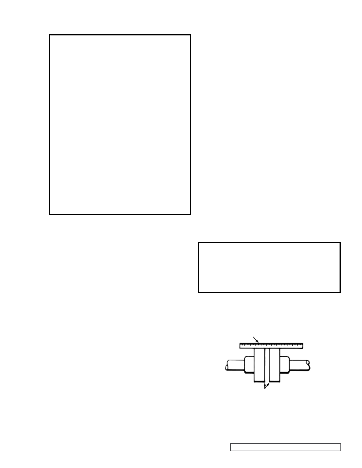
Check alignment after mounting.
1. If unit has flexible coupling, remove any coupling guards or
covers and check alignment of coupling halves. A straight
edge (piece of key stock will work) across coupling must
rest evenly on both rims at top, bottom and sides. See
Figure 1.
DANGER!
Before starting the pump, be sure all drive
equipment guards are in place.
Failure to properly mount guards may result in
serious injury or death.
2. Make final check on alignment after piping is hooked up.
USE STRAIGHT EDGE. THESE
SURFACES MUST BE PARALLEL.
CHECK WIDTH BETWEEN THESE SURFACES WITH INSIDE
CALIPERS OR FEELER GAUGE TO BE CERTAIN THE FACES
ARE EQUAL DISTANCE APART AND PARALLEL.
FIGURE 1
SECTION TSM 340.1 ISSUE D PAGE 3 OF 11
Page 4
PIPING/HOSE:
The cause of many pumping problems can be traced to
suction piping. It should always be as large in diameter and
as short in length as possible.
Before starting layout and installation of your piping system,
consider the following points:
1. Never use piping smaller than pump port connections.
Piping larger in diameter than the port connection is
sometimes required to reduce suction losses.
2. Be sure the inside of pipe is clean before installing.
3. When approaching an obstacle to the suction line, go
around instead of over it. Going over an obstacle can
create an air pocket. Where practical, slope the piping so
no air or liquid pockets will be formed. Air pockets in the
suction line make it hard for the pump to prime.
4. A strainer on the suction side of the pump should always
be considered in any pumping system. The strainer will
keep foreign matter from entering the pump. The strainer
mesh or perforation size should be large enough so that it
does not cause excessive pressure drop, but fine enough
to protect the pump. Use of a strainer is particularly
important at start up to help clean the system of weld
beads, pipe scale and other foreign objects.
5. A pressure relief valve is required in the discharge line.
See “Installation, General” page 3.
6. The pump must not be used to support the piping.
Hangers, supports, stands, etc. must carry the weight of
the pipes.
7. When fastening piping to the pump do not impose any
strain on the pump casing.
“Springing” or “drawing” the piping up to the pump will
cause distortion, possible misalignment and probable
rapid wear of the pump. Do not use the pump to correct
errors in piping layout or assembly.
8. All joints of piping system must be tight; liquid thread
sealant will help assure leak free threaded joints. Loose
joints result in liquid leaks or suction side leaks. Air leaks
make the pump noisy and reduce flow.
CAUTION: Be careful not to over tighten fittings as
this can cause cracked joints. Do not use PTFE tape.
Reduced friction makes over tightening very easy and
will result in cracked ports. Leaks in the suction line can
permit air to be drawn in, and will cause a noisy pump and
reduction in capacity.
9. Drive alignment must be checked after piping is hooked
up.
10. Provide a pressure relief device in any part of a pump
and piping system that can be valved off and, thus,
completely isolated. A rise in temperature will cause a
liquid to expand. If there is no provision for pressure relief
in the closed off section, there is a chance that the pump
or piping will rupture.
START UP:
Before pushing “start” button, check the following:
1. Vacuum and pressure gauges (liquid filled) are mounted
on or near the pump. Gauges are the quickest and most
accurate way of finding out what is happening in the
pump.
2. Pump is correctly aligned.
3. There is no pipe strain on the pump casing.
4. Rotate the pump shaft by hand to be sure it turns freely.
5. Motor has been jogged and is running in the correct
direction. Refer to “Installation, General” on page 3.
6. Pressure relief valve is installed properly.
7. Suction piping is connected and tight, and valves are
open.
8. Make sure the discharge piping is properly connected and
sealed, valves are open, and there is a place for the liquid
to go.
9. Make sure all guards are in place.
10. The above checklist is a general guideline to be used prior
to starting the pump. Since Viking Pump cannot foresee
every application for our product and possible system
design, the final responsibility is with the user. The pump
must be utilized within the catalog specifications and the
pump system must be designed to provide safe working
conditions.
The “start” button may now be pushed.
The pump should begin to deliver liquid within 15 seconds! If
not, push the stop button. Do not run the pump without liquid
flow longer than 30 seconds or the pump may be ruined.
Review Startup steps 1 through 10. Consider what the suction
and discharge gauges may indicate. If everything appears in
order, re-prime pump. Refer to “Mounting”, page 3.
Push the “start” button. If nothing is flowing within 30 seconds,
stop the pump. The pump is not a compressor, it will not build
up much air pressure. It may be necessary to vent discharge
line until liquid begins to flow.
If pump still does not deliver, consider one or more of
the following:
1. The suction line has air leaks.
2. The end of the suction pipe is not submerged deeply
enough in the liquid.
3. The suction lift is too great or the suction piping is too
small.
4. Liquid is vaporizing in the suction line before it gets to the
pump.
If after consideration of these points, the pump still does not
deliver liquid, review all points given under START UP and
read through the TROUBLESHOOTING guide and try again.
If pump still will not deliver liquid, contact your Viking Pump
supplier.
DANGER!
Before starting the pump, be sure all drive
equipment guards are in place.
Failure to properly mount guards may result
in serious injury or death.
SECTION TSM 340.1 ISSUE D PAGE 4 OF 11
MAINTENANCE:
Series SG-10 and SG-14 pumps are designed for long,
trouble-free service life under a wide variety of application
conditions with a minimum of maintenance. The points listed
below will help provide long service life.
Page 5
CLEANING PUMP: Keep pump as clean as possible. This
will facilitate inspection, adjustment and repair work.
STORAGE: If pump is to be stored, or not used for six months
or more, pump must be drained and a coat of light oil must be
applied to all internal pump parts. Viking suggests rotating
pump shaft by hand one complete revolution every 30 days
to circulate the oil. Tighten all pump assembly bolts before
putting pump in service after being stored.
SUGGESTED REPAIR TOOLS: The following tools must
be available to properly repair series SG-10 and SG-14
external gear pumps. These tools are in addition to standard
mechanics’ tools such as open-end wrenches, pliers,
screwdrivers, etc. Most of the items can be obtained from an
industrial supply house or automobile tool supplier.
1. Soft headed hammer
2. Snap ring pliers
3. Arbor press
4. Blind bearing puller set
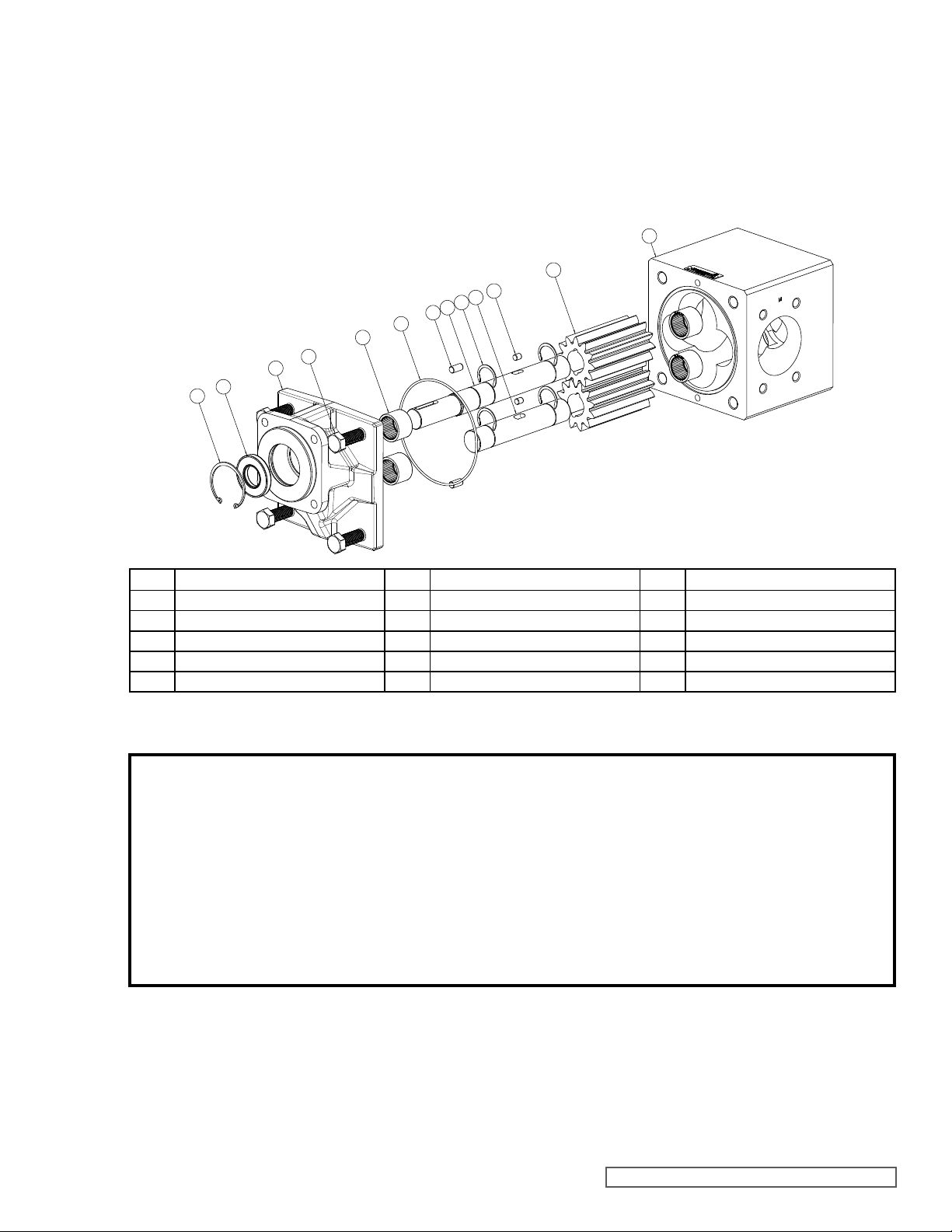
19
LIP SEAL PUMPS
2
8
4
15
13
14
12
17
11
3
20
16
ITEM NAME OF PART ITEM NAME OF PART ITEM NAME OF PART
Bracket
2
Bearings (4 Required)
3
Internal Snap Ring
4
Lip Seal
8
O-ring for Casing
11
Drive Shaft
12
Driven Shaft
13
Crescent Snap Rings (4 Required)
14
Gear Pins (2 Required)
15
Gears (2 Required)
16
Alignment Pins (2 Required)
17
Casing
19
Capscrews (4 Required)
20
FIGURE 2
EXPLODED VIEW – MODELS SG-10 AND SG-14 LIP SEAL PUMPS
DANGER !
Before opening any Viking pump liquid
chamber (pumping chamber, reservoir, relief
valve adjusting cap fitting etc.) Be sure:
1. That any pressure in chamber has been
completely vented through suction or
discharge lines or other appropriate
openings or connections.
2. That the driving means (motor, turbine,
engine, etc.) has been “locked out” or made
DISASSEMBLY:
1. Remove pump from motor or other drive equipment. If
the pump is mounted using the footed bracket (B-mount),
remove the footed bracket so the pump is flat on the work
surface.
2. Refer to Figure 2 for the names of parts.
3. Mark bracket (2) and casing (19) before disassembly to
non- operational so that it cannot be started
while work is being done on pump.
3. That you know what liquid the pump has been
handling and the precautions necessary to
safely handle the liquid. Obtain a material
safety data sheet (MSDS) for the liquid to be
sure these precautions are understood.
Failure to follow above listed precautionary
measures may result in serious injury or death.
insure proper reassembly. Remove the capscrews (20) to
separate bracket from pump casing. It may be necessary
to tap on the ears of the bracket (where capscrews are
located) with a soft headed hammer to separate the
bracket from the casing.
4. Inspect casing o-ring (11). Replace as needed.
5. Remove driven (13) and drive (12) shaft and gear
assemblies from pump.
SECTION TSM 340.1 ISSUE D PAGE 5 OF 11
Page 6
6. To remove the gears (16) from the shafts, remove both
snap rings (14) from both sides of the gear. The gears
should then slide freely off the shaft. NOTE: There is a
small pin (15) located under the gear which can fall out of
its groove when the gears are removed.
7. Inspect the gears and shafts for wear. Replace as needed.
8. Remove the internal snap ring (4) and lip seal (8) from the
bracket.
9. Inspect the bearings or bushings (3). If the bearings or
bushings need to be replaced:
Remove the bearings from the bracket and casing using a
Blind Bearing Puller. To remove carbon graphite or silicon
carbide bushings, use a cold chisel or punch to break the
bushing. Be careful not to damage the bore.
ASSEMBLY:
1. Be sure to clean the bracket and casing thoroughly. If the
bearings were removed, install new pump bearings into
each bore using an arbor press. If carbon graphite, Refer
to “Installation of Carbon Graphite Bushings” below.
3. Assemble the shaft / gear assemblies. Install one snap
ring (14) onto the shaft. Place the gear pin into its groove
on the shaft. Slide the gear over the pin and lock into place
using the second snap ring. NOTE: Proper snap ring
orientation can be seen in Figure 2. The gear pin blocks
the flow path along the gear ID in one of the grooves.
Make sure the snap rings do not block the other.
4. Coat shaft / gear assemblies with light oil. Place both
shafts in the casing with the drive shaft (longer shaft) on
the top (nameplate side).
5. Lubricate the casing O-ring using a compatible lubricant
and place it in the groove of the casing.
6. Slide the pump bracket over the gear and shaft assemblies
until flush with the casing.
7. Place the capscrews into the bracket and tighten evenly.
MODELS RECOMMENDED CAPSCREW TORQUE
SG-10 / SG-410
SG-14 / SG-414
80 ft. lbs. (110 Nm)
100 ft. lbs. (140 Nm)
MODELS BEARING PRESS DEPTH
SG-10 / SG-410
SG-14 / SG-414
0.060” - 0.080” (1.5 - 2 mm)
0.070” - 0.090” (1.8 - 2.3 mm)
2. Press the lip seal into the pump bracket using an arbor
press and install snap ring.
MECHANICAL SEAL PUMPS
12
11
17
3
20
2
10
9
8
7
6
5
4
DANGER!
Before starting the pump, be sure all drive
equipment guards are in place.
Failure to properly mount guards may result in
serious injury or death.
19
16
15
14
13
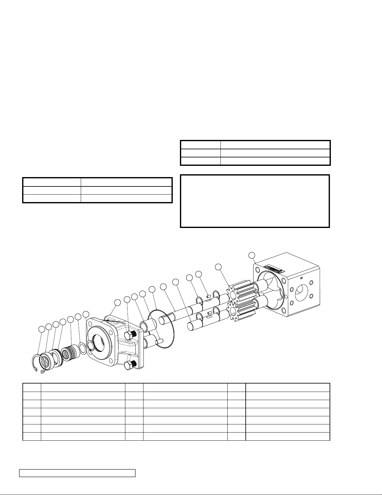
ITEM NAME OF PART ITEM NAME OF PART ITEM NAME OF PART
Bracket
2
Bearings (4 Required)
3
Internal Snap Ring
4
Outboard Bearing
5
Seal Holder
6
O-ring for Seal Holder
7
Lip Seal
8
Spacer
9
External Snap Ring
10
O-ring for Casing
11
Drive Shaft
12
Driven Shaft
13
Crescent Snap Rings (4 Required)
14
Gear Pins (2 Required)
15
Gears (2 Required)
16
Alignment Pins (2 Required)
17
Casing
19
Capscrews (4 Required)
20
FIGURE 3
EXPLODED VIEW – MODELS SG-410 AND SG-414 MECHANICAL SEAL PUMPS
SECTION TSM 340.1 ISSUE D PAGE 6 OF 11
Page 7
DANGER !
Before opening any Viking pump liquid chamber (pumping chamber, reservoir, relief valve
adjusting cap fitting etc.) Be sure:
11. Inspect the bearings or bushings (3). If the bearings or
bushings need to be replaced:
Remove the bearings from the bracket and casing using a
Blind Bearing Puller. To remove carbon graphite or silicon
carbide bushings, use a cold chisel or punch to break the
bushing. Be careful not to damage the bore.
1. That any pressure in the chamber has been
completely vented through the suction or
discharge lines or other appropriate openings
or connections.
2. That the driving means (motor, turbine,
engine, etc.) has been “locked out” or made
non- operational so that it cannot be started
while work is being done on pump.
3. That you know what liquid the pump has been
handling and the precautions necessary to
safely handle the liquid. Obtain a material
safety data sheet (MSDS) for the liquid to be
sure these precautions are understood.
Failure to follow above listed precautionary
measures may result in serious injury or death.
DISASSEMBLY:
1. Remove pump from motor or other drive equipment. If
the pump is mounted using the footed bracket (B-mount),
remove the footed bracket so the pump is flat on the work
surface.
2. Refer to Figure 3 for the names of parts.
3. Mark bracket (2) and casing (19) before disassembly to
insure proper reassembly. Remove the capscrews (20) to
separate bracket from pump casing. It may be necessary
to tap on the ears of the bracket (where capscrews are
located) with a soft headed hammer to separate the
bracket from the casing.
4. Inspect casing o-ring (11). Replace as needed.
5. Remove driven shaft (13) and gear assembly from pump.
Leave drive shaft (12) and gear assembly in place.
6. To remove the gears (16) from the shafts, remove both
snap rings (14) from both sides of the gear. The gears
should then slide freely off the shaft.
NOTE: There is a small pin (15) located under the gear
which can fall out of its groove when the gears are
removed.
7. Inspect the gears and shafts for wear. Replace as
needed.
8. Remove the internal snap ring (4) from the bracket.
9. Using a soft headed hammer tap the drive shaft, on the
gear-side, through the bracket.
10. Remove the bearing (5), seal holder (6) and mechanical
seal (8) from the shaft. Replace the bearing mechanical
seal and o-ring (7). The spacer (9) sets the working length
of the mechanical seal. Use the factory part if replacement
is necessary.
ASSEMBLY:
1. Be sure to clean the bracket and casing thoroughly. If the
bearings were removed, install new pump bearings into
each bore using an arbor press. If carbon graphite, Refer
to “Installation of Carbon Graphite Bushings” below.
MODELS BEARING PRESS DEPTH
SG-10 / SG-410
SG-14 / SG-414
2. Coat the drive shaft with light oil and place the drive gear
into the bracket (into through hole) with the snap ring on
the drive side of the bracket.
3. Assemble the shaft / gear assemblies. Install one snap
ring (14) onto each shaft (the side closest to the bracket
for the drive shaft). Place the gear pin into its groove on
each shaft. Slide the gear for each shaft over the pin and
lock into place using the second snap ring. NOTE: Proper
snap ring orientation can be seen in Figure 2. The gear
pin blocks the flow path along the gear ID in one of the
gear grooves. Make sure the snap rings do not block the
other.
4. Coat the shaft / gear assemblies with light oil. Place the
driven shaft in the blind bracket hole.
5. Lubricate the casing O-ring using a compatible lubricant
and place it in the groove of the casing.
6. Slide the pump casing over the gear and shaft assemblies
until flush with the bracket. Be sure the casing is oriented
correctly.
7. Place the capscrews into the bracket and tighten evenly.
MODELS RECOMMENDED CAPSCREW TORQUE
SG-10 / SG-410
SG-14 / SG-414
8. At this point it may be easier to tip the pump onto the
casing (drive shaft pointing up). Slide the spacer (9) over
the drive shaft until flush with the snap ring on the keyed
side of the shaft. The spacer sets the working length of
the mechanical seal. Use the factory part if replacement
is necessary.
9. Place the new stationary seat of the mechanical seal in
the seal holder with the hard face oriented outwards. The
face must be kept clean of any contaminants.
10. Check to be sure the drive shaft is free of any burrs,
particularly in the keyway. Lightly lubricate the ID of the
elastomeric bellows on the rotating part of the mechanical
seal and the area on the shaft where it will be located.
Once the bellows has been lubricated the pump must be
assembled in approximately 5 minutes. Carefully slide the
rotating part of the seal onto the shaft until it contacts the
spacer. The flat carbon face must be facing the keyway
and be kept clean of any contaminants.
SECTION TSM 340.1 ISSUE D PAGE 7 OF 11
0.060” - 0.080” (1.5 - 2 mm)
0.070” - 0.090” (1.8 - 2.3 mm)
80 ft. lbs. (110 Nm)
100 ft. lbs. (140 Nm)
Page 8
11. Slide the seal holder (seal seat facing rotating face) over
the shaft and into the bracket until it contacts the rotating
face. Be careful that the o-ring does not get damaged
during installation.
12. Slide the outboard bearing over the shaft until it contacts
the seal holder.
13. Force will need to be exerted on the bearing to overcome
the seal spring force in order to install the internal snap
ring. Install the internal snap ring.
DANGER!
Before starting the pump, be sure all drive
equipment guards are in place.
Failure to properly mount guards may result in
serious injury or death.
INSTALLATION OF CARBON
GRAPHITE BUSHINGS:
When installing carbon graphite bushings, extreme care must
be taken to prevent breaking. Carbon graphite is a brittle
material and is easily cracked. If cracked, the bushing will
quickly disintegrate. Using a lubricant and adding a chamfer
on the bushing and the mating part will help in installation.
The additional precautions listed below must be followed for
proper installation.
1. A press must be used for installation.
2. Be certain bushing is started straight.
3. Do not stop pressing operation until bushing is in proper
position. Starting and stopping will result in a cracked
bushing.
4. Check bushing for cracks after installation.
Carbon graphite bushings with extra interference fits are
frequently furnished for high temperature operation. These
bushings must be installed by a shrink fit.
1. Heat bracket for idler to 750ºF.
2. Install cool bushing with a press.
3. If facilities are not available to reach 750ºF. temperature,
it is possible to install with 450ºF. temperature; however
the lower the temperature the greater the possibility of
cracking the bushing.
Consult factory with specific questions on high temperature
applications.
DANGER !
Before opening any Viking pump liquid
chamber (pumping chamber, reservoir, relief
valve adjusting cap fitting etc.) Be sure:
1. That any pressure in chamber has been
completely vented through suction or
discharge lines or other appropriate
openings or connections.
2. That the driving means (motor, turbine,
engine, etc.) has been “locked out” or made
non- operational so that it cannot be started
while work is being done on pump.
3. That you know what liquid the pump has been
handling and the precautions necessary to
safely handle the liquid. Obtain a material
safety data sheet (MSDS) for the liquid to be
sure these precautions are understood.
Failure to follow above listed precautionary
measures may result in serious injury or death.
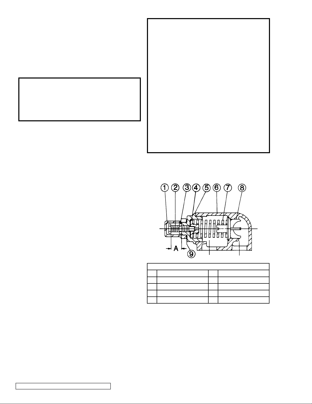
PRESSURE RELIEF VALVE
INSTRUCTIONS:
VALVE - LIST OF PARTS
1. Valve Cap 6. Valve Body
2. Adjusting Screw 7. Valve Spring
3. Lock Nut 8. Poppet
4. Spring Guide 9. Cap Gasket
5. Bonnet
SECTION TSM 340.1 ISSUE D PAGE 8 OF 11
FIGURE 4
Page 9
DANGER !
Before opening any Viking pump liquid
chamber (pumping chamber, reservoir, relief
valve adjusting cap fitting etc.) Be sure:
1. That any pressure in chamber has been
completely vented through suction or
discharge lines or other appropriate
openings or connections.
2. That the driving means (motor, turbine,
engine, etc.) has been “locked out” or made
non- operational so that it cannot be started
while work is being done on pump.
3. That you know what liquid the pump has been
handling and the precautions necessary to
safely handle the liquid. Obtain a material
safety data sheet (MSDS) for the liquid to be
sure these precautions are understood.
Failure to follow above listed precautionary
measures may result in serious injury or death.
DISASSEMBLY – RELIEF VALVE:
Mark the valve and head before disassembly to ensure
proper reassembly.
1. Remove the valve cap.
2. Measure and record the length of extension of the
adjusting screw. Refer to “A” on Figure 4.
3. Loosen the locknut and back out the adjusting screw until
spring pressure is released.
4. Remove the bonnet, spring guide, spring and poppet from
the valve body. Clean and inspect all parts for wear or
damage and replace as necessary.
ASSEMBLY – RELIEF VALVE:
Reverse the procedures outlined under DISASSEMBLY –
RELIEF VALVE. If the valve is removed for repairs, be sure
to replace in the original position. The relief valve adjusting
screw cap must always point towards the suction side of
the pump. If the pump rotation is reversed, remove the relief
valve and turn end for end.
PRESSURE ADJUSTMENT:
If a new spring is installed or if pressure setting of pressure
relief valve is to be changed from that which the factory has
set, the following instructions must be carefully followed.
1. Carefully remove valve cap which covers adjusting screw.
Loosen locknut which locks adjusting screw so pressure
setting will not change during operation of pump.
2. Install a pressure gauge in discharge line for actual
adjusting operation.
3. Turn adjusting screw in to increase pressure and out to
decrease pressure.
4. With discharge line closed at point beyond pressure
gauge, gauge will show maximum pressure valve will
allow while pump is in operation.
TROUBLESHOOTING:
A Viking pump that is properly installed and maintained will
give long satisfactory performance.
If trouble does develop, one of the first steps toward finding
the difficulty is to install a vacuum gauge in the suction line
and a pressure gauge in the discharge line. Readings on
these gauges often give a clue on where to start looking for
trouble.
VACUUM GAUGE - SUCTION PORT:
High vacuum reading would indicate:
1. The suction line is blocked, valve closed, a strainer is
plugged or a pinched suction line.
2. The suction line is too small.
3. The liquid is too viscous to flow through the piping.
4. The lift required is too high.
Low reading would indicate:
1. There may be an air leak in the suction line.
2. The end of the pipe is not in the liquid.
3. The pump is worn.
4. The pump is dry and should be primed.
Fluttery, jumping or erratic reading would indicate:
1. The liquid is vaporizing.
2. Liquid is coming in to the pump in slugs, possibly an air
leak or insufficient liquid above the end of the suction
pipe.
3. Vibration from cavitation, misalignment, or damaged parts.
PRESSURE GAUGE - DISCHARGE PORT:
High reading would indicate:
1. High viscosity and small diameter and/or lengthy
discharge line.
2. A downstream strainer or filter is plugged.
3. The pressure relief valve is set too high.
4. Valve in the discharge line partially closed.
5. Line partially plugged from build up on inside of pump,
solidified product or foreign object.
6. Liquid in the pipe not up to temperature.
Low reading would indicate:
1. Pressure relief valve set too low.
2. Pressure relief valve poppet not seating properly.
3. Pump assembly bolts not torqued to specifications.
4. The bypass around pump partially open.
5. Pump is damaged or worn.
6. The pump has too much internal clearance.
SECTION TSM 340.1 ISSUE D PAGE 9 OF 11
Page 10

Fluttery, jumping or erratic reading would indicate:
1. Cavitation.
2. Liquid is coming to the pump in slugs.
3. Air leak in the suction line.
4. Vibrating from misalignment or mechanical problems.
MISCELLANEOUS:
Pump does not pump:
1. The pump has lost its prime from air leak or low level in
tank.
2. The suction lift is too high.
3. Rotating in the wrong direction.
4. The motor does not come up to speed.
5. The strainer is clogged.
6. The bypass valve is open, pressure relief valve set too
low or pressure relief valve poppet stuck open.
7. The pump is worn out.
8. Any changes in liquid, system or operation that would
help explain the trouble, e.g. new liquid, additional lines
or process changes.
Pump starts, then loses its prime:
1. The supply tank is empty.
2. The liquid is vaporizing in the suction line.
3. There is an air leak or air pockets in the suction line.
4. The pump is worn out.
Pump is noisy:
1. The pump is cavitating (liquid vaporizing in suction line)
or being starved (heavy liquid cannot get to pump fast
enough). Increase the suction pipe size and/or reduce
the length, or decrease the pump speed. If the pump is
above the liquid, raise the liquid level closer to the center
line of the inlet port. If the liquid is above the pump,
increase the head of the liquid.
2. Check alignment.
3. Anchor the base or piping to eliminate vibration.
Pump not delivering up to capacity:
1. The pump is starving or cavitating – see Pump is noisy,
item 1.
2. The strainer partially clogged.
3. Air leak somewhere in the suction line.
4. Running too slow. Is the motor the correct speed and
wired up correctly?
5. Pressure relief valve is set too low, stuck open or has
damaged poppet seat.
6. The bypass line around the pump partially opened.
7. The pump is worn out.
Pump takes too much power (stalls motor):
1. Liquid is more viscous than the is unit sized to handle.
2. The system pressure relief valve set too high.
3. The pump is misaligned.
DO’S AND DON’TS:
Do’s and Don’ts for installation, operation and maintenance
of Viking pumps to assure safe, long, trouble free operation.
Installation:
1. DO install the pump as close to supply tank as possible.
2. DO leave working space around the pumping unit.
3. DO use large, short and straight suction port.
4. DO install a strainer in the suction line.
5. DO a double check of alignment after unit is mounted
and piping is hooked up.
6. DO provide pressure relief valve for discharge side of
pump.
7. DO check for proper rotation.
8. DO use piping, hose and fittings rated for maximum
system pressure.
Operation:
1. DON’T run the pump at speeds faster than 1800 RPM.
2. DON’T allow the pump to develop pressure higher than
those shown in catalog at that size.
3. DON’T operate pumps at temperatures above or below
limits shown in catalog for model.
4. DON’T operate unit without all guards in place.
5. DON’T operate pump without pressure relief valve in
discharge piping; be sure valve is mounted and set
correctly.
6. DON’T stick fingers in ports of pump!!! Fingers may be
pinched between gears.
7. DON’T work on the pump unless driver has been “locked
out” so it cannot be started while work is being done on
the pump.
Maintenance:
1. DO record pump model number and serial number and
file for further use.
2. DO have spare parts, pump or stand by units available,
particularly if pump is essential part of key operation
process.
3. DO obtain, read and keep all maintenance instructions
furnished with this pump.
IMPORTANT:
In ordering parts for pressure relief valve, always give
model number and serial number of pump as it appears on
nameplate and name of part wanted. When ordering springs,
be sure to give pressure setting desired.
SECTION TSM 340.1 ISSUE D PAGE 10 OF 11
Page 11
TECHNICAL SERVICE MANUAL
EXTERNAL GEAR PUMPS
SERIES SG-10, -14
WARRANTY
Viking warrants all products manufactured by it to be
free from defects in workmanship or material for a
period of one (1) year from date of startup, provided
that in no event shall this warranty extend more than
eighteen (18) months from the date of shipment from
Viking. The warranty period for Universal Seal series
pumps ONLY (Universal Seal models listed below) is
three (3) years from date of startup, provided that in
no event shall this warranty extend more than forty-two
(42) months from the date of shipment from Viking.
UNDER NO CIRCUMSTANCES SHALL VIKING BE
LIABLE UNDER THIS WARRANTY OR OTHERWISE
FOR SPECIAL, INCIDENTAL, INDIRECT,
CONSEQUENTIAL OR PUNITIVE DAMAGES OF ANY
KIND, INCLUDING, BUT NOT LIMITED TO, LOST
OR UNREALIZED SALES, REVENUES, PROFITS,
INCOME, COST SAVINGS OR BUSINESS, LOST OR
UNREALIZED CONTRACTS, LOSS OF GOODWILL,
DAMAGE TO REPUTATION, LOSS OF PROPERTY,
LOSS OF INFORMATION OR DATA, LOSS OF
PRODUCTION, DOWNTIME, OR INCREASED
COSTS, IN CONNECTION WITH ANY PRODUCT,
EVEN IF VIKING HAS BEEN ADVISED OR PLACED
ON NOTICE OF THE POSSIBILITY OF SUCH
DAMAGES AND NOTWITHSTANDING THE FAILURE
OF ANY ESSENTIAL PURPOSE OF ANY PRODUCT.
THIS WARRANTY IS AND SHALL BE VIKING’S SOLE
AND EXCLUSIVE WARRANTY AND SHALL BE IN
LIEU OF ALL OTHER WARRANTIES, EXPRESS
OR IMPLIED, INCLUDING, BUT NOT LIMITED
TO, ALL WARRANTIES OF MERCHANTABILITY,
FITNESS FOR A PARTICULAR PURPOSE AND
NON-INFRINGEMENT ALL OF WHICH OTHER
WARRANTIES ARE EXPRESSLY EXCLUDED.
See complete warranty at www.vikingpump.com.
SECTION TSM 340.1
PAGE 11 OF 11
ISSUE D
VIKING PUMP, INC. • A Unit of IDEX Corporation • Cedar Falls, IA 50613 USA
© 8/2013 Viking Pump Inc.
All rights reserved
 Loading...