

Page 1
Electronic copies of the most current TSM issue can be found on the Viking Pump website at www.vikingpump.com
TECHNICAL SERVICE MANUAL
Viking® In-Line Helical Gear Reducers
Sizes 12, 22, 32, 36, 41, 51, 61, 70, 80, 90, 100
CONTENTS
Introduction ............................................................................. 1
Storage ................................................................................... 2
Lubrication .............................................................................. 2
Oil Quantity
Periodic Oil Changes
Plug Locations ........................................................................ 3
Radial and Overhung Loads ................................................... 3
Troubleshooting ...................................................................... 4
Repair Parts............................................................................ 4
Warranty ................................................................................. 5
INTRODUCTION
The illustrations used in this manual are for identification
purposes only. This manual deals only with in-line reducers.
Speed reducer specifications and recommendations are listed
in Catalog Section 615, In-Line Helical Gear Reducers.
SECTION TSM 615
PAGE 1 OF 5
ISSUE I
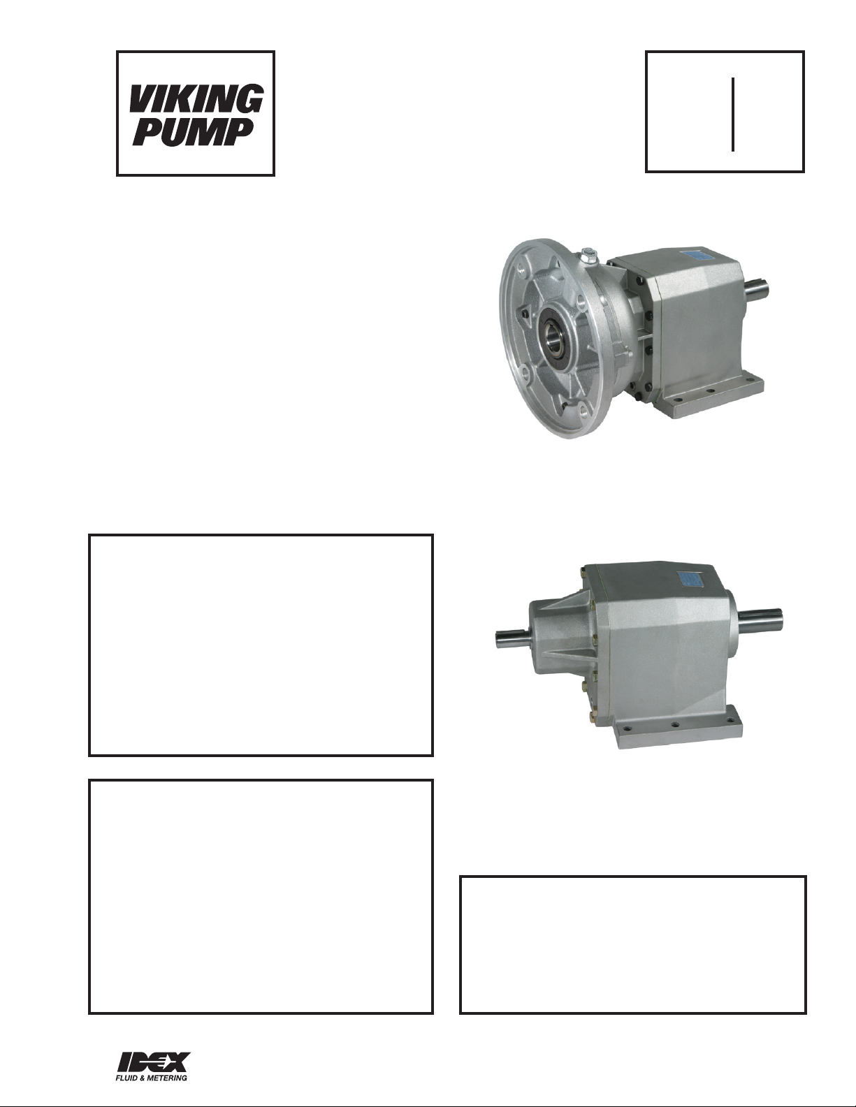
FIGURE 1
SIZE 22 WITH NEMA C-FACE ADAPTOR
DANGER !
Before removing any Viking reducer from
its unit be sure: that the driving means (motor,
turbine, engine, etc.) has been “locked out”
or made non-operational so that it cannot
be started while work is being done on the
reducer or driven equipment.
Failure to follow above listed precautionary
measures may result in serious injury or death.
DANGER !
Incorrect installation, operation or maintenance
of equipment may cause severe personal injury
or death and/or equipment damage.
This information must be read fully before
beginning installation, operation or maintenance and must be kept with the reducer. It is
suggested that suitably trained or qualified
persons perform all installation and maintenance procedures.
FIGURE 2
SIZE 32 WITH SOLID INPUT SHAFT
CAUTION !
To avoid oxidation and possible seizure of the
motor shaft to the NEMA-C or IEC motor flange
adaptor bore, apply an anti-seize product to the
motor shaft prior to assembly.
VIKING PUMP, INC. • A Unit of IDEX Corporation • Cedar Falls, IA 50613 USAVIKING PUMP, INC. • A Unit of IDEX Corporation • Cedar Falls, IA 50613 USA
Page 2
STORAGE
Observe the following instructions to ensure correct storage of
products:
A) Do not store outdoors, in areas exposed to weather or with
excessive humidity.
B) Always place boards, wood, or other material between the
products and the floor. The gearbox should not have direct
contact with the floor.
C) For long term storage (over 60 days), all machined surfaces
such as flanges, shafts and couplings must be protected
with a suitable rust inhibiting product (Mobilarma 248 or
equivalent).
D) The following measures must be taken when products are
stored for a period exceeding 6 months:
• For life lubricated products, the machined areas must be
greased to prevent oxidation.
• In addition to above, products originally supplied without
oil must be positioned with the breather plug at the highest
point and filled with oil.
Before operating the speed reducer, restore the correct
quantity of oil.
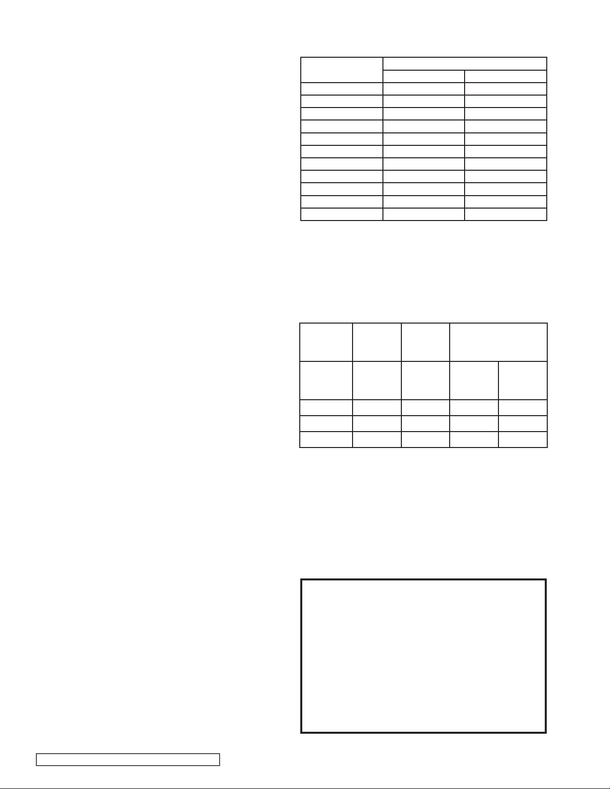
Table 1
Oil Quantity
Size
12 * 0.95 .45
22 * 1.69 0.80
32 * 3.0 1.4
36 * 3.4 1.6
41 * 4.6 2.2
51 6.6 3.1
61 8.9 4.2
70 14 6.5
80 23 11
90 40 19
100 57 27
* Indicates Life Lubricated
It must be emphasized that these quantities are only
indicative and users should check the correct level through
the sight glass.
Pints Liters
LUBRICATION
Gear units are oil-bath lubricated. For applications calling for
speed reducers with vertical shaft orientation, oil coverage
during operation would not be sufficient to ensure correct
lubrication of upper bearings, suitable life lubrication systems
must be used.
Speed reducer sizes 12 - 41 are supplied pre-filled with oil and
do not have oil filling or level plugs. These long-life lubricated
units (using synthetic oil) are capable of operating at an
ambient temperature range of -4°F (-20°C) to 122°F (50°C).
For temperatures below -4°F (-20°C), contact your authorized
distributor or Viking Technical Service.
Speed reducers sizes 51 - 100 require oil filling by the user.
Before start-up, fill with the correct quantity of oil using
Table 1. These quantities are approximate, use the sight
glass on the unit to fill accurately. When filled correctly, the
oil level should be in the center of the sight glass. Choose
the viscosity and type of oil from Table 2 that is appropriate
for the ambient temperature. Viking highly recommends the
use of synthetic oil as it maintains viscosity properties over a
broader temperature range, shear rates and time. In addition,
synthetic oils usually contain additives that prevent foaming
and rusting, such as Mobil SHC 600 series, Texaco Synlube
CLP series or equivalents. These speed reducers are supplied
with oil fill, level, and drain plugs.
Contact your authorized distributor or Viking Technical Service
for vertical or other mounting arrangements.
Table 2
Ambient
Temperature
Duty
Load
Light Duty 150 150 220 220
Medium Duty 150 150 320 220
Heavy Duty 220 220 460 320
32 – 70° F
(0 – 20°C)
Mineral
Oil
ISO VG
-4 – 70° F
(-20 – 20°C)
Synthetic
Oil
ISO VG
70 – 104° F
(20 – 40°C)
Mineral
Oil
ISO VG
Synthetic Oil
ISO VG
Periodic Oil Changes
Periodic oil changes are not required for sizes 12 - 41 as
they are lubricated for life with synthetic oil. The remaining
sizes 51 – 100 are designed for oil lubrication and have oil fill,
level, and drain plugs, see “Plug Locations”. Users should
replace the oil based on Table 3 and following the directions
in “Lubrication”.
CAUTION !
Sizes 12, 22, 32, 36, 41 are pre-filled with
synthetic lubricant when shipped and require
no additional lubricant. These sizes have
no oil filling or level plugs. Sizes 51 – 100
require filling with correct amount and type of
lubricant prior to use. Operating reducer
without the proper type and amount of
lubricant for even a short period of time may
cause damage.
SECTION TSM 615 ISSUE I PAGE 2 OF 5
Page 3
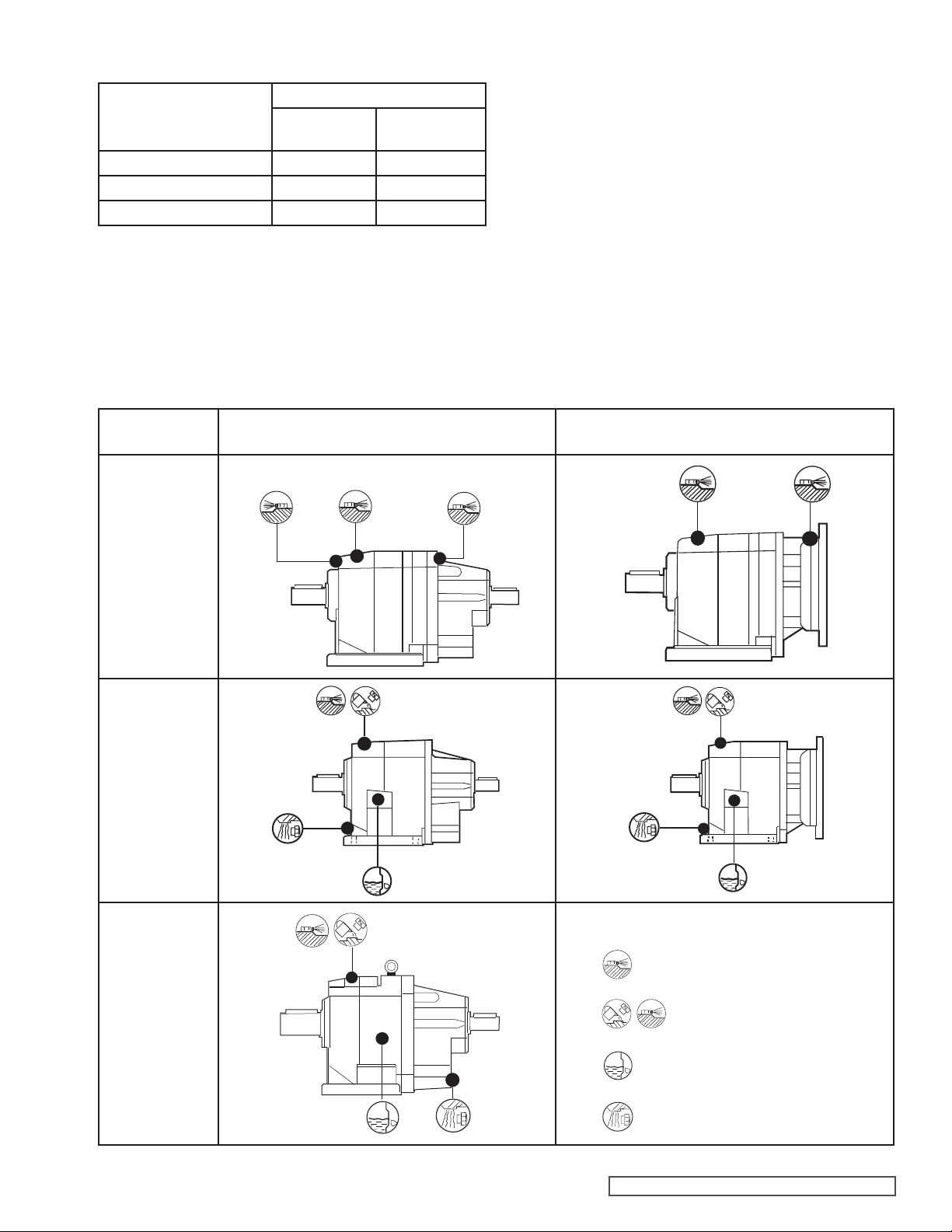
Table 3
Oil
Temperature
<150° F (<65°C) 8000 25000
150-175°F (65 – 80°C) 4000 15000
175–200°F (80–95°C) 2000 12500
Oil Change Interval (Hrs)
Mineral
Oil
Synthetic
Oil
PLUG LOCATIONS
The breather plug, fill/breather plug, level plug and drain plug
locations are shown below. The C12-C41 reducers are filled
and shipped with a synthetic oil and, therefore, do not have
fill or level plugs. The C51-C100 reducers must be filled at
installation and have a level plug mounted on the side. The
plug locations are shown below.
HS NEMA and IEC
C-12
C36, C41
C22, C32
Breather units are not installed at the factory. Remove the
breather plug and replace with the breather unit (typically
taped to the side of the unit).
C36, C41
C12- C41
C51-C61
C70-C100
Symbols
Breather Plug
Fill / Breather Plug
Level Plug / Sight Glass
Drain Plug
SECTION TSM 615 ISSUE I PAGE 3 OF 5
Page 4
RADIAL AND OVERHUNG LOADS
Input and output shaft of the speed reducer can be subject
to loading generated by the type of transmission fitted on
the shaft itself. Acceptable overhung load levels can be
calculated. Contact your Authorized Distributor or Viking
Technical Support for assistance.
TROUBLESHOOTING
Some of the following may help pinpoint the problem:
Bearing temperature is too high:
• Oil level is too low
• Oil is old
• Bearings are worn¹
Operating temperature is too high:
• Oil level is too high
• Oil is old
• Impurities or contaminates are in the oil
Excessive running noise:
• Gears are damaged¹
• Bearing axial backlash is too high¹
• Bearings are worn¹
• Service load is too high
• Impurities or contaminates are in the oil
Excessive noise at the gear unit mounting:
• Mounting bolts are loose
• Mounting bolts are worn
Oil leakage:
• Oil level is too high
• Casing/coupling seals worn
• Gaskets worn
Gear unit does not run or runs with difficulty:
• Oil viscosity is too high
• Oil level is too high
• Service load is too high
Output shaft does not turn with motor running
• Gears are damaged¹
¹ Sizes 51-100: Replace gear subassemblies or bearings,
see “Repair Parts”. Sizes 12-41: Replace entire unit.
REPAIR PARTS
Special tools and training are required to repair multireduction gearboxes. Replacement of gears, shafts and
bearings, combined with labor makes repairs impractical.
Oil seals and gaskets can be easily replaced without special
tools or training.
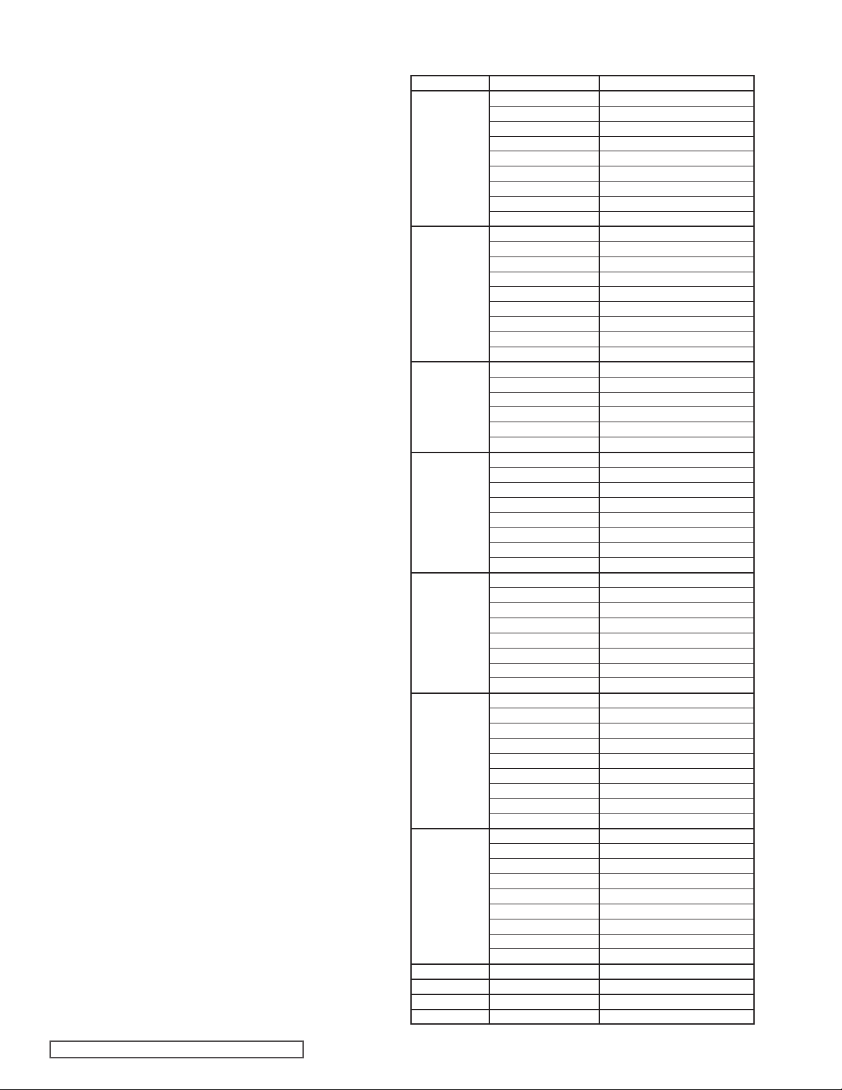
Repair parts for in-line reducers are limited to seal kits
consisting of oil seals and gaskets. Table 4 lists the part
number for the repair kit for each reducer size and
configuration.
Table 4
Size
12
22
32
36
41
51
61
70 Solid Shaft 3-462-ILINE70-001
80 Solid Shaft 3-462-ILINE80-001
90 Solid Shaft 3-462-ILINE90-001
100 Solid Shaft 3-462-ILINE100-001
Input Shaft Repair Kit No.
Solid Shaft 3-462-ILINE12-001
56C 3-462-ILINE12-002
143/145TC 3-462-ILINE12-003
182/184TC 3-462-ILINE12-004
63 IEC 3-462-ILINE12-005
71 IEC 3-462-ILINE12-006
80 IEC 3-462-ILINE12-007
90 IEC 3-462-ILINE12-008
100/112 IEC 3-462-ILINE12-009
Solid Shaft 3-462-ILINE22-001
56C 3-462-ILINE22-002
143/145 TC 3-462-ILINE22-003
182/184 TC 3-462-ILINE22-004
63 IEC 3-462-ILINE22-005
71 IEC 3-462-ILINE22-006
8O IEC 3-462-ILINE22-007
90 IEC 3-462-ILINE22-008
100/112 IEC 3-462-ILINE22-009
Solid Shaft 3-462-ILINE32-001
143/145 TC 3-462-ILINE32-002
182/184 TC 3-462-ILINE32-003
80 IEC 3-462-ILINE32-004
90 IEC 3-462-ILINE32-005
100/112 IEC 3-462-ILINE32-006
Solid Shaft 3-462-ILINE36-001
143/145 TC 3-462-ILINE36-002
182/184 TC 3-462-ILINE36-003
213/215 TC 3-462-ILINE36-004
80 IEC 3-462-ILINE36-005
90 IEC 3-462-ILINE36-006
100/112 IEC 3-462-ILINE36-007
132 IEC 3-462-ILINE36-008
Solid Shaft 3-462-ILINE41-001
143/145 TC 3-462-ILINE41-002
182/184 TC 3-462-ILINE41-003
213/215TC 3-462-ILINE41-004
80 IEC 3-462-ILINE41-005
90 IEC 3-462-ILINE41-006
100/112 IEC 3-462-ILINE41-007
132 IEC 3-462-ILINE41-008
Solid Shaft 3-462-ILINE51-001
182/184 TC 3-462-ILINE51-002
213/215 TC 3-462-ILINE51-003
254/256 TC 3-462-ILINE51-004
284/286 TC 3-462-ILINE51-005
100/112 IEC 3-462-ILINE51-006
132 IEC 3-462-ILINE51-007
160 IEC 3-462-ILINE51-008
180 IEC 3-462-ILINE51-009
Solid Shaft 3-462-ILINE61-001
182/184 TC 3-462-ILINE61-002
213/215TC 3-462-ILINE61-003
254/256 TC 3-462-ILINE61-004
284/286 TC 3-462-ILINE61-005
100/112 IEC 3-462-ILINE61-006
132 3-462-ILINE61-007
160 3-462-ILINE61-008
180 3-462-ILINE61-009
SECTION TSM 615 ISSUE I PAGE 4 OF 5
Page 5
TECHNICAL SERVICE MANUAL
Viking® In-Line Helical Gear Reducers
Sizes 12, 22, 32, 36, 41, 51, 61, 70, 80, 90, 100
WARRANTY
Viking warrants all products manufactured by it to be
free from defects in workmanship or material for a
period of one (1) year from date of startup, provided
that in no event shall this warranty extend more than
eighteen (18) months from the date of shipment from
Viking. The warranty period for Universal Seal series
pumps ONLY (Universal Seal models listed below) is
three (3) years from date of startup, provided that in
no event shall this warranty extend more than forty-two
(42) months from the date of shipment from Viking.
UNDER NO CIRCUMSTANCES SHALL VIKING BE
LIABLE UNDER THIS WARRANTY OR OTHERWISE
FOR SPECIAL, INCIDENTAL, INDIRECT,
CONSEQUENTIAL OR PUNITIVE DAMAGES OF ANY
KIND, INCLUDING, BUT NOT LIMITED TO, LOST
OR UNREALIZED SALES, REVENUES, PROFITS,
INCOME, COST SAVINGS OR BUSINESS, LOST OR
UNREALIZED CONTRACTS, LOSS OF GOODWILL,
DAMAGE TO REPUTATION, LOSS OF PROPERTY,
LOSS OF INFORMATION OR DATA, LOSS OF
PRODUCTION, DOWNTIME, OR INCREASED
COSTS, IN CONNECTION WITH ANY PRODUCT,
EVEN IF VIKING HAS BEEN ADVISED OR PLACED
ON NOTICE OF THE POSSIBILITY OF SUCH
DAMAGES AND NOTWITHSTANDING THE FAILURE
OF ANY ESSENTIAL PURPOSE OF ANY PRODUCT.
THIS WARRANTY IS AND SHALL BE VIKING’S SOLE
AND EXCLUSIVE WARRANTY AND SHALL BE IN
LIEU OF ALL OTHER WARRANTIES, EXPRESS
OR IMPLIED, INCLUDING, BUT NOT LIMITED
TO, ALL WARRANTIES OF MERCHANTABILITY,
FITNESS FOR A PARTICULAR PURPOSE AND
NON-INFRINGEMENT ALL OF WHICH OTHER
WARRANTIES ARE EXPRESSLY EXCLUDED.
See complete warranty at www.vikingpump.com.
SECTION TSM 615
PAGE 5 OF 5
ISSUE I
VIKING PUMP, INC. • A Unit of IDEX Corporation • Cedar Falls, IA 50613 USA
© 8/2014 Viking Pump Inc.
All rights reserved
 Loading...