


Viking Pump TSM344 User Manual
Electronic copies of the most current TSM issue can be found on the Viking Pump website at www.vikingpump.com
TECHNICAL SERVICE MANUAL
COMPOSITE MAG DRIVE PUMPS
MODELS E02, E05, E12, E25, E75 AND E125
CONTENTS
Introduction . . . . . . . . . . . . . . . . . . . . . . . 1
Special Information . . . . . . . . . . . . . . . . . . . 1
Safety Information. . . . . . . . . . . . . . . . . . . . 2
Maintenance . . . . . . . . . . . . . . . . . . . . . . 3
Exploded Views . . . . . . . . . . . . . . . . . . . . . 4
E02 . . . . . . . . . . . . . . . . . . . . . . . . . . 4
E05 . . . . . . . . . . . . . . . . . . . . . . . . . . 5
E12 . . . . . . . . . . . . . . . . . . . . . . . . . . 6
E25 . . . . . . . . . . . . . . . . . . . . . . . . . . 7
E75 and E125 . . . . . . . . . . . . . . . . . . . . 8
Disassembly/Assembly - E02 . . . . . . . . . . . . . . 9
Disassembly . . . . . . . . . . . . . . . . . . . . . 9
Inspection. . . . . . . . . . . . . . . . . . . . . . .10
Assembly . . . . . . . . . . . . . . . . . . . . . . .10
Disassembly/Assembly - E05 and E12 . . . . . . . . .12
Disassembly . . . . . . . . . . . . . . . . . . . . .12
Inspection. . . . . . . . . . . . . . . . . . . . . . .13
Assembly . . . . . . . . . . . . . . . . . . . . . . .13
Disassembly/Assembly - E25, E75 and E125 . . . . .15
Disassembly . . . . . . . . . . . . . . . . . . . . .15
Inspection. . . . . . . . . . . . . . . . . . . . . . .16
Assembly . . . . . . . . . . . . . . . . . . . . . . .16
Inspection and Wear Limits . . . . . . . . . . . . . . .18
Service and Replacement Limits . . . . . . . . . . . .18
Troubleshooting Chart . . . . . . . . . . . . . . . . .19
Bolt Torque Recommendations . . . . . . . . . . . . .20
ATEX Directive . . . . . . . . . . . . . . . . . . . . .21
Temperature Class and Max. Liquid Temperatures . . .21
Sample Tag . . . . . . . . . . . . . . . . . . . . . . .22
Normal Operation . . . . . . . . . . . . . . . . . . . .23
Expected Malfunction . . . . . . . . . . . . . . . . . .23
SECTION TSM 344
CMD SERIES
PAGE 1 Of 24
ISSUE f
ATTENTION !
To ensure safe handling and operating
situations, please thoroughly review
all of the warnings listed on the
following page.
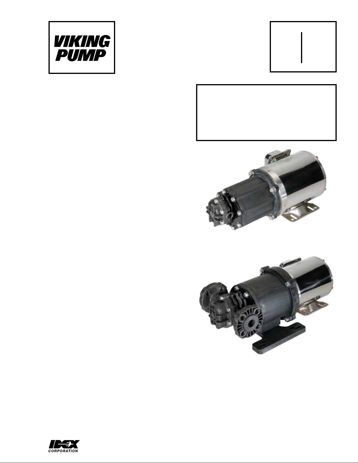
FIGURE 1
MODEL E05 WITH MOTOR
INTRODUCTION
The illustrations used in this manual are for identification
purposes only and cannot be used for ordering parts. Obtain
a parts list from the factory or a Viking representative. Always
give a complete name of the part, part number and material
with the model number and serial number of pump when
ordering repair parts. The unmounted pump or pump unit
model number and serial number are on the nameplate.
This manual deals only with CMD Series Composite Mag
Drive Pumps. Refer to Figures 1 through 47 for general
configuration and nomenclature used in this manual. Pump
specifications and recommendations are listed in Catalog
Section 344.
VIKING PUMP, INC. • A Unit of IDEX Corporation • Cedar Falls, IA 50613 USA
FIGURE 2
MODEL E25 WITH MOTOR
SPECIAL INFORMATION
ROTATION: Shaft rotation determines which port is suction
and which is discharge. Viewed from shaft end, with clockwise
rotation, the right port is suction and left port is discharge.
With counterclockwise rotation, the left port is suction and
right port is discharge.
SAFETY INFORMATION
INCORRECT INSTALLATION, OPERATION OR MAINTENANCE OF EQUIPMENT MAY CAUSE SEVERE
PERSONAL INJURY OR DEATH AND/OR EQUIPMENT DAMAGE AND MAY INVALIDATE THE WARRANTY.
This information must be read fully before beginning installation, operation or maintenance and must be
kept with the pump. All installation and maintenance must be undertaken by suitably trained or qualified
persons only.
Warning - Safety instructions which
shall be considered for reasons of safe
operation of the pump or pump unit and/
or protection of the pump or pump unit
itself are marked by this symbol.
Symbol
Legend :
Danger - Failure to follow the listed
precautionary measures identified by
this symbol may result in serious injury
!
or death.
WARNING
!
!
!
!
!
WARNING
!
!
DO NOT OPERATE PUMP IF:
– The front cover is not installed correctly.
– Any guards are missing or incorrectly installed.
– The suction or discharge piping is not connected.
DO NOT place fingers, etc. into the pumping chamber
or its connection ports or into any part of the drive train
if there is ANY possibility of the pump shafts being
rotated. Severe injury will occur.
DO NOT exceed the pumps rated pressure, speed, and
temperature, or change the system/duty parameters
from those for which the pump was originally supplied,
without confirming its suitability for the new duty.
INSTALLATION AND OPERATION OF THE PUMP
MUST ALWAYS COMPLY WITH HEALTH AND
SAFETY REGULATIONS.
Rare earth magnets used in couplings have
extremely strong magnetic fields capable of
changing performance or damaging items such as:
Pacemakers, Metal Implants, Watches, Computers
& Disks, and Credit Cards
Completely assembled magnetic couplings will
not affect items listed above - only disassembled
components.
There are no known harmful effects of these
magnetic fields on the human body.
A device must be incorporated into the pump, system,
or drive to prevent the pump exceeding its stated duty
pressure. It must be suitable for both directions of
pump rotation where applicable. Do not allow pump
to operate with a closed/blocked discharge unless a
pressure relief device is incorporated. If an integral
relief valve is incorporated into the pump, do not allow
re-circulation through the relief valve for extended
periods.
The mounting of the pump or pump unit should be
solid and stable. Pump orientation must be considered
in relation to drainage requirements. Once mounted,
shaft drive elements must be checked for correct
alignment. Rotate pump shaft by at least one full
revolution to ensure smoothness of operation.
Incorrect alignment will produce excessive loadings
and will create high temperatures and increased noise
emissions. Do not use any drive arrangements which
cause sideloading of the drive shaft.
The installation must allow safe routine maintenance
and inspection (to check for leakage, monitor
pressures, etc) and provide adequate ventilation
necessary to prevent overheating.
WARNING
WARNING
WARNING
!
!
!
!
!
!
Before operating the pump, be sure that it and all
parts of the system to which it is connected are clean
and free from debris and that all valves in the suction
and discharge pipelines are fully opened. Ensure that
all piping connecting to the pump is fully supported
and correctly aligned with its relevant connections.
Misalignment and/or excess loads will cause severe
pump damage.
Be sure that pump rotation is correct for the desired
direction of flow.
DO NOT INSTALL THE PUMP INTO A SYSTEM
WHERE IT WILL RUN DRY (I.E. WITHOUT A
SUPPLY OF PUMPED MEDIA).
Pressure gauges/sensors are recommended, next
to the pump suction and discharge connections to
monitor pressures.
Caution must be taken when lifting the pump. Suitable
lifting devices should be used as appropriate. Lifting
eyes installed on the pump must only be used to lift
the pump, not pump with drive and/or baseplate. If
pump is baseplate mounted, the base plate must be
used for all lifting purposes. If slings are used for lifting,
they must be safely and securely attached. For weights
of bare shaft pumps refer to catalog.
DO NOT attempt any maintenance or disassembly of
the pump or pump unit without first ensuring that :
– The pump is fully isolated from the power source
(electric, hydraulic, pneumatic).
– The pumping chamber, relief valve and any
shaft seal support system are depressurized and
purged.
– Any temperature control devices (jackets, heat-
tracing, etc) are fully isolated, that they are
depressurized and purged, and components are
allowed to reach a safe handling temperature.
DO NOT attempt to dismantle a pressure relief valve
which has not had the spring pressure relieved or is
mounted on a pump that is operating. Serious personal
injury or death and/or pump damage may occur.
DO NOT loosen or undo the front cover, any
connections to the pump, shaft seal housings,
temperature control devices, or other components,
until sure that such action will not allow the unsafe
escape of any pressurized media.
Pumps and/or drives can produce sound power levels
exceeding 85 dB(A) under certain operating conditions.
When necessary, personal protection against noise
must be taken.
Avoid any contact with hot parts of pumps and/or
drives which may cause injury. Certain operating
conditions, temperature control devices (jackets, heattracing, etc.), bad installation, or poor maintenance
can all promote high temperatures on pumps and/or
drives.
SECTION TSM 344 ISSUE F PAGE 2 OF 24
SPECIAL INFORMATION (CONT’D)
PRESSURE RELIEF VALVES:
1. Viking pumps are positive displacement pumps and
must be provided with some sort of pressure protection.
This may be an inline pressure relief valve, a torquelimiting device, or a rupture disk, or other method.
NOTE: Pump can be operated in reverse direction for
short duration at low differential pressure to clean/flush
out lines.
2. If pump rotation is to be reversed during operation,
pressure protection must be provided on both sides
of the pump.
3. Pressure relief valves cannot be used to control pump
flow or regulate discharge pressure.
For additional information on pressure relief valves, refer
to Technical Service Manual TSM000 and Engineering
Service Bulletin ESB-31.
MAINTENANCE
Series CMD pumps are designed for long, trouble-free
service life under a wide variety of application conditions with
a minimum of maintenance. The following points will help
provide long service life.
Pumps that are mounted directly to the motor will need to be
removed from the mounting bracket to perform mechanical
seal maintenance or replacement.
CLEANING PUMP: Keep the pump as clean as possible.
This will facilitate inspection, adjustment, and repair work.
STORAGE: If pump is to be stored, or not used for six
months or more, the pump must be drained and a light coat
of light oil must be applied to all internal pump parts.
Apply grease to the pump shaft extension. Viking suggests
rotating pump shaft by hand one complete revolution every
30 days to circulate the oil. Tighten all pump assembly bolts
before putting the pump in service after being stored.
DANGER !
Before opening any Viking pump liquid
chamber (pumping chamber, reservoir,
relief valve adjusting cap fitting, etc.)
Be sure:
1. That any pressure in the chamber has
been completely vented through the
suction or discharge lines or other
appropriate openings or connections.
2. That the driving means (motor,
turbine, engine, etc.) has been
“locked out” or made non-operational
so that it cannot be started while
work is being done on pump.
3. That you know what liquid the
pump has been handling and the
precautions necessary to safely
handle the liquid. Obtain a material
safety data sheet (MSDS) for the
liquid to be sure these precautions
are understood.
Failure to follow above listed
precautionary measures may result in
serious injury or death.
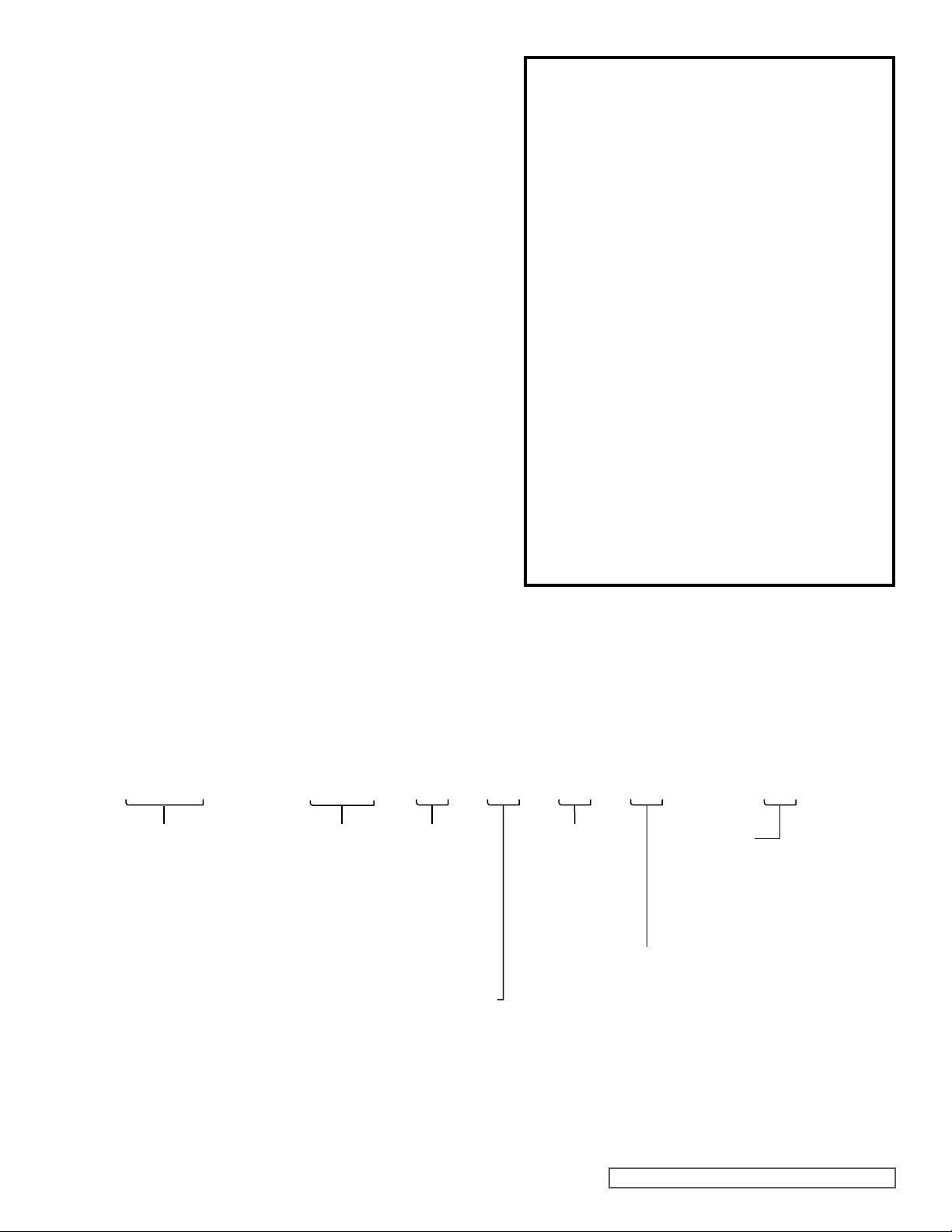
CMD - E02 E L V F - X
Series:
Composite Mag Drive
* Export license required under U.S. Export
Administration ECCN 28350 and 28999.
Viton® is a registered trademark of DuPont Performance Elastomers.
Model:
E02
E05
E12 *
E25 *
E75 *
E125 *
Materials/Ports:
E = ETFE, FNPT
(E02, E05, E12
B = ETFE, ISO 7-1
(E02, E05, E12
F = ETFE, Flange
(E25, E75, E125
O-Rings:
V = Viton
)
)
)
Bearings:
L = Carbon Graphite
B = Graphite-Impregnated
Silicon-Carbide
E = EPDM
®
Mounting Arrangement:
F = NEMA 56C (E02, E05, E12, E25
O = NEMA 143TC-182C (E05, E12, E25, E75, E125
R = NEMA 182TC-184TC (E75, E125
H = IEC B34 63 (E02, E05, E12
K = IEC B34 80 (E02, E05, E12
P = IEC B14 100/112 (E25, E75, E125
Y = No Motor Mount Kit (E02, E05, E12, E25, E75, E125
SECTION TSM 344 ISSUE F PAGE 3 OF 24
Options:
A = Bearing Flush Ports
B = Combination of Options A and N
N = Without Drive Magnet
X = Complete Pump (No Options
)
)
)
)
)
)
)
)
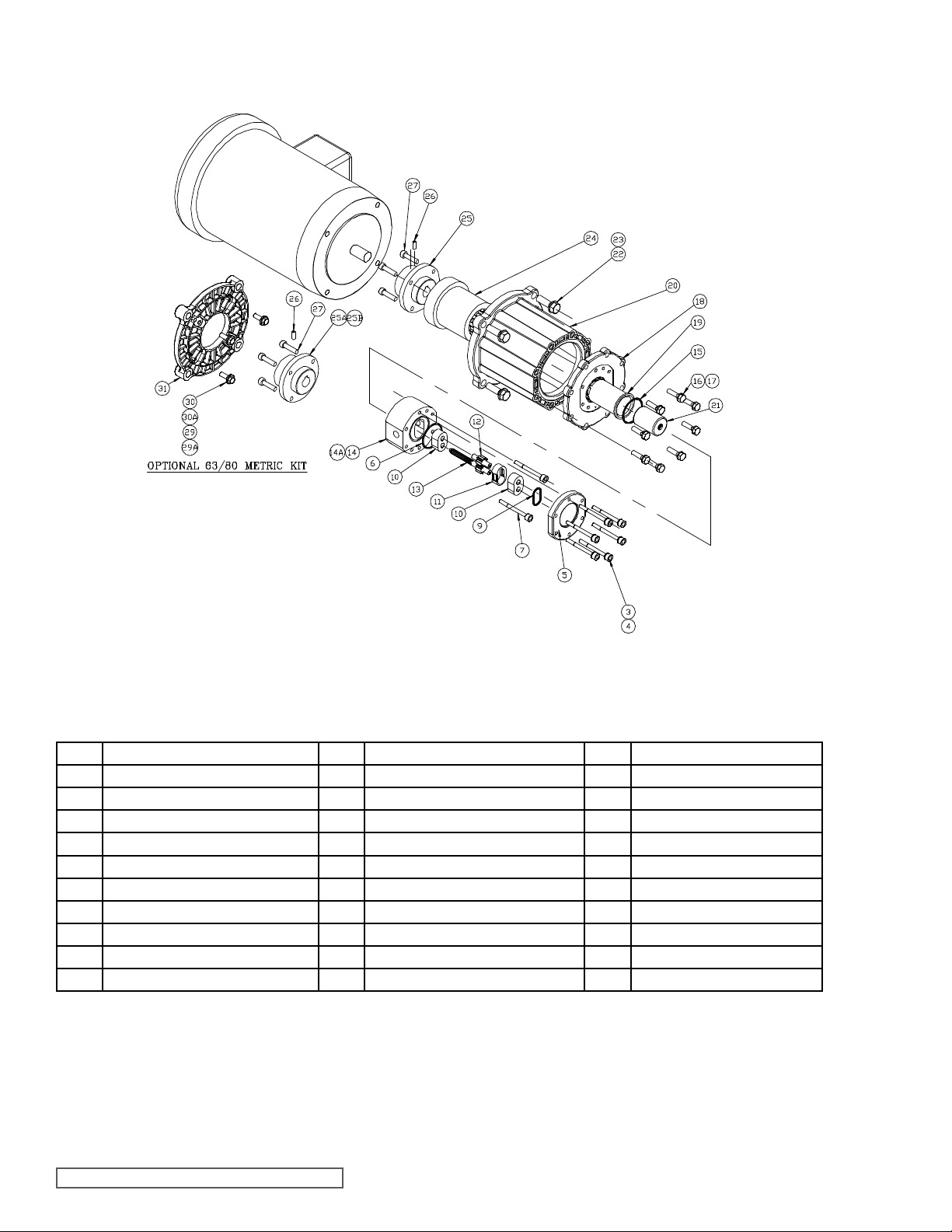
E02
EXPLODED VIEW OF E02 PUMP (TYPICAL)
Item Description Item Description Item Description
2 Drive Screw 13 Drive Gear Assembly * 23 Washer
3 Bolts 14 Center Housing 24 Drive Magnet
4 Washers 15 O-Ring, Containment Canister * 25 Coupling Hub
5 Front Cover 16 Bolts 26 Set Screw
6 O-Ring, Cover * 17 Washers 27 Screws
7 Bolts 18 Adapter, Canister 29 Bolts
9 O-Ring, Compression * 19 Containment Canister 30 Washer
10 Bearing * 20 Adapter, Spool 31 Adapter, Motor
11 Housing Liner * 21 Driven Magnet Assembly
12 Idler Gear Assembly * 22 Bolts
* Recommended spare parts.
SECTION TSM 344 ISSUE F PAGE 4 OF 24
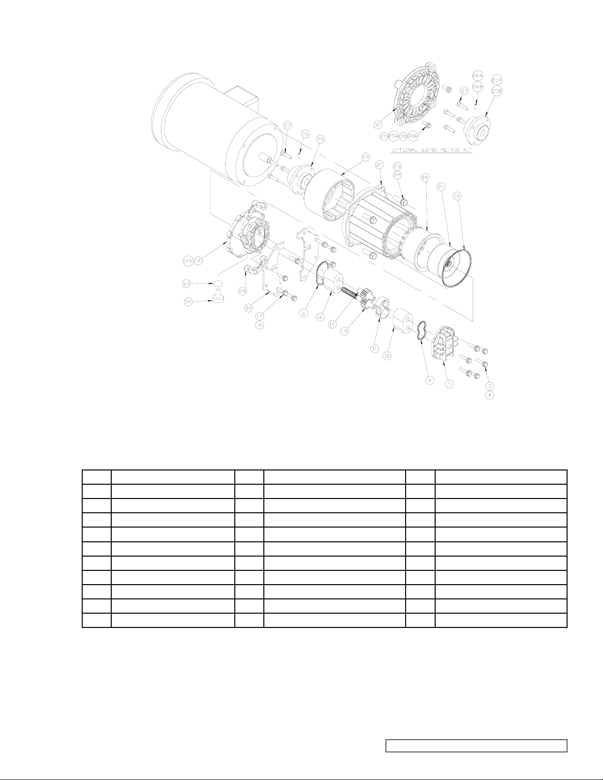
E05
EXPLODED VIEW OF E05 PUMP (TYPICAL)
Item Description Item Description Item Description
2 Drive Screw 14 Center Housing 25 Coupling Hub
3 Bolts 15 O-Ring, Containment Canister * 26 Set Screw
4 Washers 16 Bolts 27 Screws
5 Front Cover 17 Washers 28 Nut Plate
6 O-Ring, Cover * 19 Containment Canister 29 Bolts
9 O-Ring, Compression * 20 Adapter, Spool 30 Washer
10 Bearing * 21 Driven Magnet Assembly 31 Adapter, Motor
11 Housing Liner * 22 Bolts 32 Retaining Plate
12 Idler Gear Assembly * 23 Washer 33 O-Ring, Drain Plug *
13 Drive Gear Assembly * 24 Drive Magnet 34 Drain Plug
* Recommended spare parts.
SECTION TSM 344 ISSUE F PAGE 5 OF 24
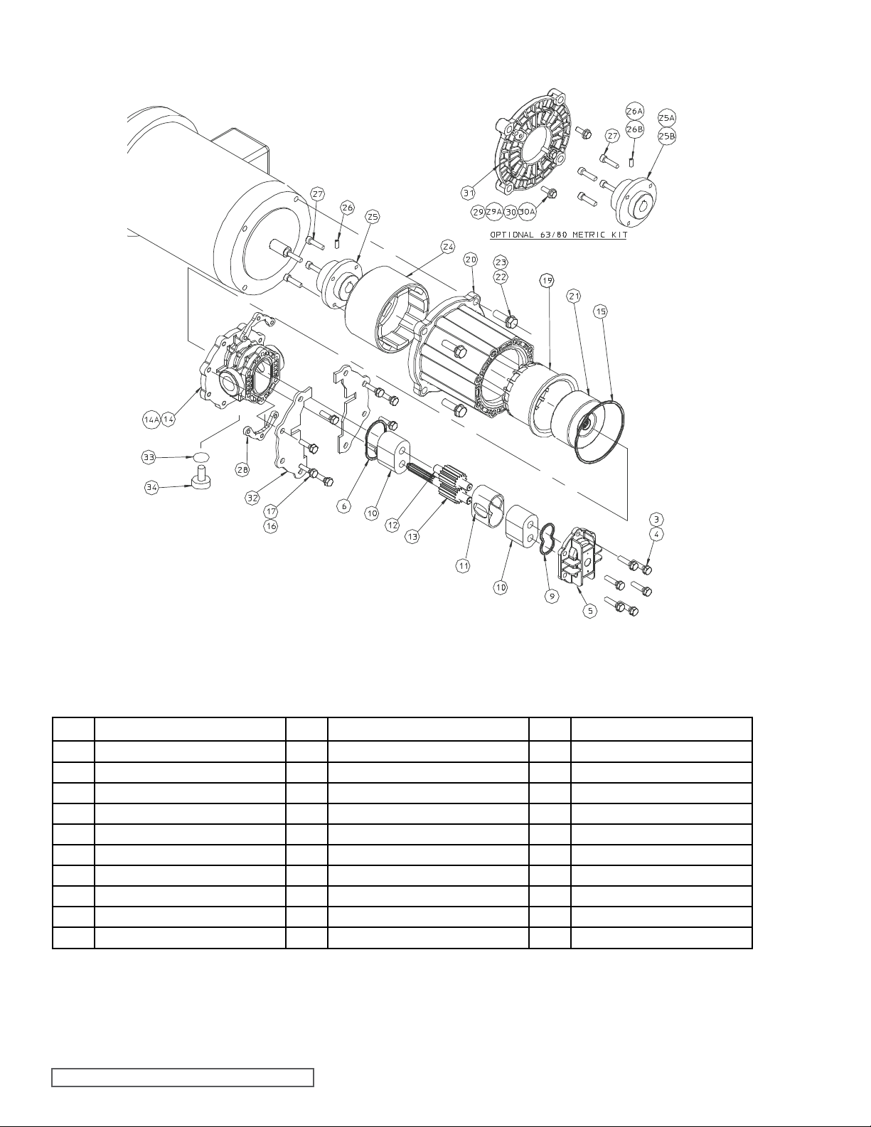
E12
EXPLODED VIEW OF E12 PUMP (TYPICAL)
Item Description Item Description Item Description
2 Drive Screw 14 Center Housing 25 Coupling Hub
3 Bolts 15 O-Ring, Containment Canister * 26 Set Screw
4 Washers 16 Bolts 27 Screws
5 Front Cover 17 Washers 28 Nut Plate
6 O-Ring, Cover * 19 Containment Canister 29 Bolts
9 O-Ring, Compression * 20 Adapter, Spool 30 Washer
10 Bearing * 21 Driven Magnet Assembly 31 Adapter, Motor
11 Housing Liner * 22 Bolts 32 Retaining Plate
12 Idler Gear Assembly * 23 Washer 33 O-Ring, Drain Plug *
13 Drive Gear Assembly * 24 Drive Magnet 34 Drain Plug
* Recommended spare parts.
SECTION TSM 344 ISSUE F PAGE 6 OF 24

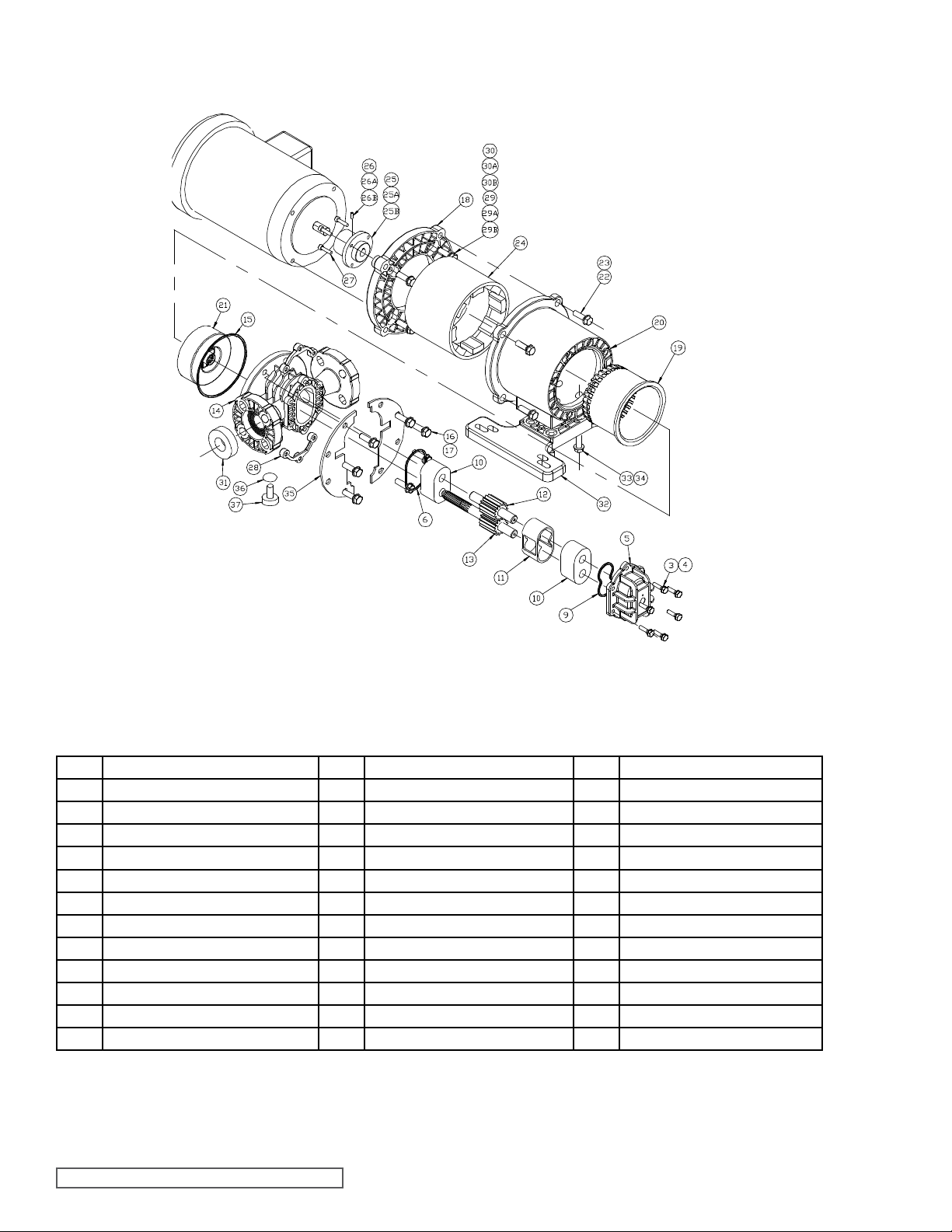
E25
EXPLODED VIEW OF E25 PUMP (TYPICAL)
Item Description Item Description Item Description
2 Drive Screw 16 Bolts 28 Nut Plates
3 Bolts 17 Washers 29 Bolts
4 Washers 18 Adapter, Motor 30 Washer
5 Front Cover 19 Containment Canister 31 Flange Gaskets
6 O-Ring, Cover * 20 Adapter, Spool 32 Mounting Base
9 O-Ring, Compression * 21 Driven Magnet Assembly 33 Bolt
10 Bearing * 22 Bolt 34 Washer
11 Housing Liner * 23 Washer 35 Retaining Plate
12 Idler Gear Assembly * 24 Drive Magnet 36 O-Ring, Drain Plug *
13 Drive Gear Assembly * 25 Coupling Hub 37 Drain Plug
14 Center Housing Flange 26 Set Screw
15 O-Ring, Containment Canister * 27 Screws
* Recommended spare parts.
SECTION TSM 344 ISSUE F PAGE 7 OF 24
E75 AND E125
EXPLODED VIEW OF E75 AND E125 PUMPS (TYPICAL)
Item Description Item Description Item Description
2 Drive Screw 16 Bolts 28 Nut Plates
3 Bolts 17 Washers 29 Bolts
4 Washers 18 Adapter, Motor 30 Washer
5 Front Cover 19 Containment Canister 31 Flange Gaskets
6 O-Ring, Cover * 20 Adapter, Spool 32 Mounting Base
9 O-Ring, Compression * 21 Driven Magnet Assembly 33 Bolt
10 Bearing * 22 Bolt 34 Washer
11 Housing Liner * 23 Washer 35 Retaining Plate
12 Idler Gear Assembly * 24 Drive Magnet 36 O-Ring, Drain Plug *
13 Drive Gear Assembly * 25 Coupling Hub 37 Drain Plug
14 Center Housing Flange 26 Set Screw
15 O-Ring, Containment Canister * 27 Screws
* Recommended spare parts.
SECTION TSM 344 ISSUE F PAGE 8 OF 24