

Viking Pump TSM343.1 User Manual
TECHNICAL SERVICE MANUAL
VI-CORR® MAG DRIVE® COMPOSITE PUMPS
SERIES RP- 805 & RP- 807
CONTENTS
with model number and series number of pump when
MODEL NUMBER CHART
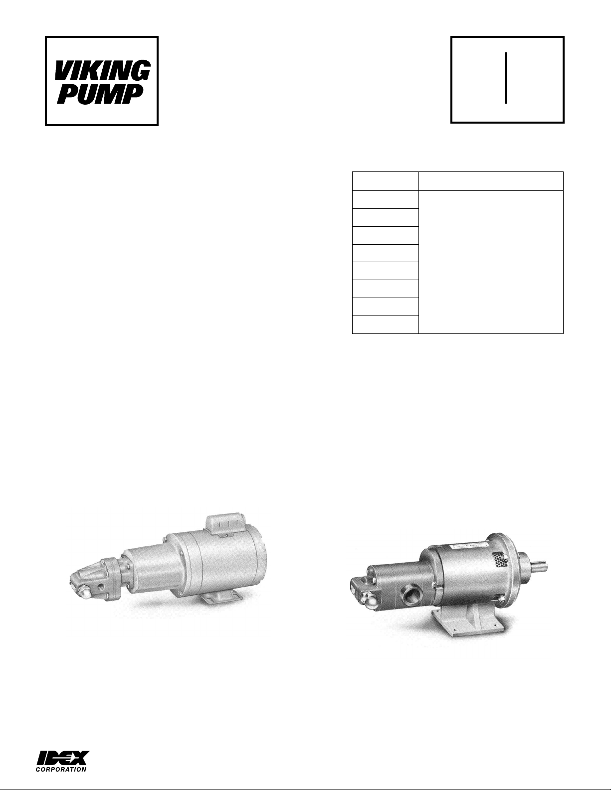
UNMOUNTED
PUMPS
FIGURE 1
FIGURE 2
SECTION TSM 343.1
PAGE 1 OF 13
ISSUE C
Electronic copies of the most current TSM issue can be found on the Viking Pump website at www.vikingpump.com
INTRODUCTION 1
SPECIAL INFORMATION 2
INSTALLATION 2
DISASSEMBLY OF MD-A2, MD-A8, MD-B15
or MD-B40 COUPLINGS 4
GENERAL PUMP DISASSEMBLY 8
RP-805 SERIES PUMP DISASSEMBLY 8
RP-805 SERIES PUMP ASSEMBLY 8
RP-807 SERIES PUMP DISASSEMBLY 9
RP-807 SERIES PUMP ASSEMBLY 9
ASSEMBLY OF MD-A2, MD-A8, MD-B15 or
MD-B40 COUPLINGS 9
TROUBLESHOOTING 11
DO'S AND DON'S 12
INTRODUCTION
TECHNICAL SERVICE MANUAL
VI-CORR® MAG DRIVE® COMPOSITE PUMPS
SERIES RP-805 & RP-807
RP-80525
RP-80550
RP-80570
RP-80514
RP-80782
RP-80716
RP-80724
RP-80732
SECTION TSM 343.1
PAGE 1 OF 13
ISSUE E
Units are designated by the
unmounted pump model numbers
followed by a letter indicating drive
M = Motor Mounted (Close Coubled
B = Bearing Carrier Mounted
R = Viking Reducer Drive
P = Commercial Reducer Drive
(Example RP-80514-MD-A8B)
UNITS
style.
D = Direct Drive
C-Flange)
The illustrations in this manual are for identification purposes
only and cannot be used for ordering parts. Obtain a parts list
from the factory or a Viking
nature of the pump and the close manufacturing tolerances,
certain replacement parts are only available in assemblies.
Always give complete name of part, part number or material
ordering repair parts. The pump or pump unit model number
and serial number are on the nameplate.
In the Viking® model number system, the first number "8"
indicates a magnetic coupled design. The next two numbers
determine the pump series ad the last two numbers indicate
pump size.
® representative. Due to the
The RP-805 Series gear pumps mount to the MD-A2 or MDA8 coupling. The larger RP-807 Series gear pumps are
available with the MD-A2, MD-A8, MD-B15 or MD-B40
couplings.
This manual deals only with RP Series composite pumps.
Refer to figures 1 thru 20 for general configuration and
nomenclature used in this manual. Pump specifications and
recommendations are listed in Catalogue Section 343.
SERIES RP-805 PUMP
MOTOR CONNECTED TO
FOOTLESS BRACKET AND PUMP
VIKING PUMP, INC. • A Unit of IDEX Corporation • Cedar Falls, IA 50613 USA
SERIES RP-807 PUMP
BEARING CARRIER, FOOTED BRACKET
AND MOUNTED PUMP

SPECIAL INFORMATION
3. If a relief valve is not furnished on the pump, some means
If pump rotation is to be reversed during normal
Check alignment after mounting of units with a bearing
THAT ANY PRESSURE IN CHAMBER HAS
BEEN COMPLETELY VENTED THROUGH
APPROPRIATE OPENINGS OR
THAT THE DRIVING MEANS (MOTOR,
HAS BEEN HANDLING AND THE
NECESSARY TO SAFELY
SAFETY DATA SHEET (MSDS) FOR THE
FAILURE TO FOLLOW ABOVE LISTED
DANGER
HE PUMP IN THE OPPOSITE
DANGER
BEFORE OPENING ANY VIKING PUMP LIQUID
CHAMBER (PUMPING CHAMBER, RESERVOIR,
RELIEF VALVE ADJUSTING CAP FITTING ETC.)
BE SURE:
1.
SUCTION OR DISCHARGE LINES OR OTHER
CONNECTIONS.
2.
TURBINE, ENGINE, ETC.) HAS BEEN “LOCKED
OUT” OR MADE NON- OPERATIONAL SO THAT
IT CANNOT BE STARTED WHILE WORK IS
BEING DONE ON PUMP.
3. THAT YOU KNOW WHAT LIQUID THE PUMP
PRECAUTIONS
HANDLE THE LIQUID. OBTAIN A MATERIAL
LIQUID TO BE SURE THESE PRECAUTIONS
ARE UNDERSTOOD.
PRECAUTIONARY MEASURES MAY RESULT IN
SERIOUS INJURY OR DEATH.
of over pressure protection such as an in-line relief valve
should be provided.
4.
operation, pressure protection must be provided on both
sides of pump.
5. Relief valve adjusting screw cap must always point
towards suction side of pump.
6. Pressure relief valves cannot be used to control flow to
regulate pressure.
For additional information on pressure relief valves, refer to
Technical Service Manual TSM 000 and Engineering Service
Bulletin ESB-31.
INSTALLATION
General
The following items must be considered prior to pump
installation:
1. Location - locate the pump as close as possible to supply
of liquid being pumped. If possible locate pump below
liquid supply. Viking pumps are self-priming; but, the
better the suction conditions the better the pump will
perform.
2. Accessibility - pump must be accessible for inspection,
maintenance and repair.
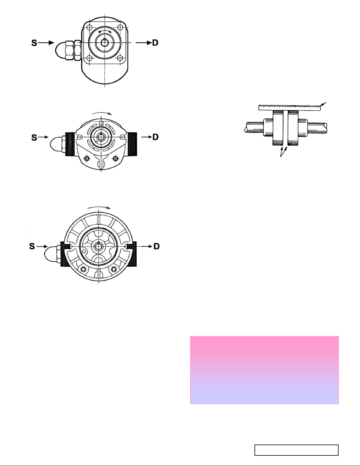
3. Suction/Discharge - SG Series pumps are designed for
clockwise rotation as standard (viewed from end of shaft).
Refer to Figure 3.
Mounting
Rotation:
Although shaft rotation determines which port is suction and
which is discharge, Viking magnetic drive composite pumps
are designed to run in a designated direction (indicated on
pump decal).
RUNNING T
DIRECTION TO THE DESIGNATED DIRECTION
MAY RESULT IN SERIOUS INJURY OR DEATH.
Pressure Relief Valves:
1. Relief valves are mounted on the head or casing of all
RP series composite pumps.
2. The RP series is a positive displacement pump and
requires some sort of over pressure protection. Without
over pressure protection, the following is likely to occur:
motor stalls, drive equipment fails, a pump part breaks
and the piping and/or equipment in the system bursts.
This may be an internal relief valve.
TSM 343.1 ISSUE D PAGE 2 OF 13
1. The pump mounting surface must be clean and flat.
2. Use SAE Grade 5 or better capscrews to mount pump.
3. The mounting capscrews for RP-05 & RP-07 pumps must
have a minimum of ½ inch thread engagement.
4. Mechanical Seal and Lip Seals RP Series pumps are
designed to be used with jaw type couplings that do not
induce axial thrust on the pump shaft. If an improper type
coupling is used, internal damage may result.
5. Do not strike or press inner magnet coupling half to install
on the pump shaft. Damage to pump or coupling may
result if coupling does not slide onto pump shaft, inspect
coupling bore, shaft and key for nicks or burrs and
remove if present.
6. Once pump has been mounted, place a small amount of
compatible liquid into suction port and turn by hand to
ensure pump turns freely.
Alignment
carrier.
1. If unit has flexible coupling, remove any coupling guards
or covers and check alignment of coupling halves. A
straight edge (piece of key stalk will work) across coupling
must rest evenly on both rims at top, bottom and sides.
See Figure 4.
2. Make final check on alignment after piping is hooked up.
Replace the guards.
Piping/Hose
4. A strainer on the suction side of the pump should always
protect the pump without causing excessive pressure
areful not to over tighten fittings as this can cause
is needed for proper connection. Do not use Teflon tape.
Clockwise Rotation RP-805
CW ROTATION
(viewed from shaft end)
Clockwise Rotation RP-807 (MD-B)
CHECK WIDTH BETWEEN THESE SURFACES WITH
INSIDE CALIPERS TO BE CERTAIN THE FACES ARE
EQUAL DISTANCE APART AND PARALLEL.
be considered in any pumping system. The straining will
keep foreign matter from entering the pump. The strainer
mesh or perforation size should be as fine as possible to
drop. Use of a strainer is particularly important at start up
to help clean the system of weld beads, pipe scale and
other foreign objects.
5. A pressure relief valve is required in the discharge line.
See Pressure Relief Valves, SPECIAL INFORMATION,
page 2.
(viewed from shaft end)
Clockwise Rotation RP-807 (MD-A)
CW ROTATION
USE STRAIGHT EDGE. THESE SURFACES MUST BE PARALLEL
COUPLING
ALIGNMENT
FIGURE 4
6. Pump must not be used to support piping. Weight of pipe
must be carried by hangers, supports, stands, etc.
7. When fastening to the pump to impose any strain on
pump casing. "Springing" or "drawing" piping up to pump
will cause distortion; possible misalignment and probable
rapid wear of pump. Do not use pipe to correct errors in
piping layout or assembly.
8. All joints of piping system must be tight; liquid thread
sealant will help assure leak free threaded joints. Loose
joints result in liquid leaks or suction side leaks. Air leaks
make the pump noisy and reduce flow. CAUTION: Be
c
cracked joints. One full turn beyond hand tight is all that
(viewed from shaft end)
FIGURE 3
The cause of many pumping problems can be traced to
suction piping. It should always be as large in diameter and
as short in length as possible.
Before starting layout and installation of your piping system,
consider the following points:
1. Never use piping smaller than pump port connections.
Piping larger in diameter than the port connection is
sometimes is required to reduce suction losses.
2. Be sure the inside of pipe is clean before installing.
3. When approaching an obstacle in the suction line, go
around instead of over it. Going over obstacle creates an
air pocket. Where practical slope piping, slope piping so
no air or liquid pockets will be formed. Air pockets in
suction line make it hard for the pump to prime.
Reduced friction makes over tightening very easy and will
result in cracked ports.
9. Drive alignment must be checked after piping is hooked
up.
10. Provide a pressure relief device if any part of a pump and
piping system that can be valved off, thus completely
isolated. A rise in temperature will cause liquid to expand.
With no provision for pressure relief in the closed off
section, there is a chance that the pump or piping will
rupture.
BEFORE STARTING PUMP, BE SURE ALL DRIVE
Start Up:
EQUIPMENT GUARDS ARE ADEQUATE AND IN
DANGER
PLACE.
FAILURE TO PROPERLY MOUNT GUARDS MAY
RESULT IN SERIOUS INJURY OR DEATH.
Before pushing "start" button, check the following:
1. Vacuum and pressure gauges (liquid filled) are mounted
on or near the pump. Gauges are the quickest and most
accurate way of finding out what is happening in the
pump.
TSM 343.1 ISSUE D PAGE 3 OF 13
2. Check Pump alignment (See page 3).
Review steps just outlined. Consider what suction and
4. Arbor press
5. Torque wrench
DISASSEMBLY OF MD-A2, MD-A8,
MD-B15, or MD-B40 COUPLINGS
1.
Read all of the instructions before proceeding with
disassembly of the coupling and/or pump. Remove
piping to ports and remove the mounting capscrews
securing pump to bracket. Support larger pumps with
overhead hoist if possible. Remove pump from coupling
bracket. See FIGURE 6 on page 4.
2. Canister will probably be full of liquid, use care while
removing from pump and pull straight off. Loosen both
setscrews and pull off inner magnet assembly. MD-A2
and MD-A8 couplings require removing the pipe plug in
pump bracket to gain access to the setscrews holding
the inner magnet.
Don't forget this is a very powerful magnet. Do not
remove O-ring on bracket unless you plan to replace -
especially the encapsulated O-rings. Follow instructions
in ASSEMBLY
for installation of a new Teflon®
encapsulated O-ring.
3. You should be able to visually inspect other magnets
from end of bracket. If removal is necessary, start by
removing (4) capscrews and separating from motor or
bearing carrier. Loosen setscrews in outer magnet
assembly to pull assembly off shaft.
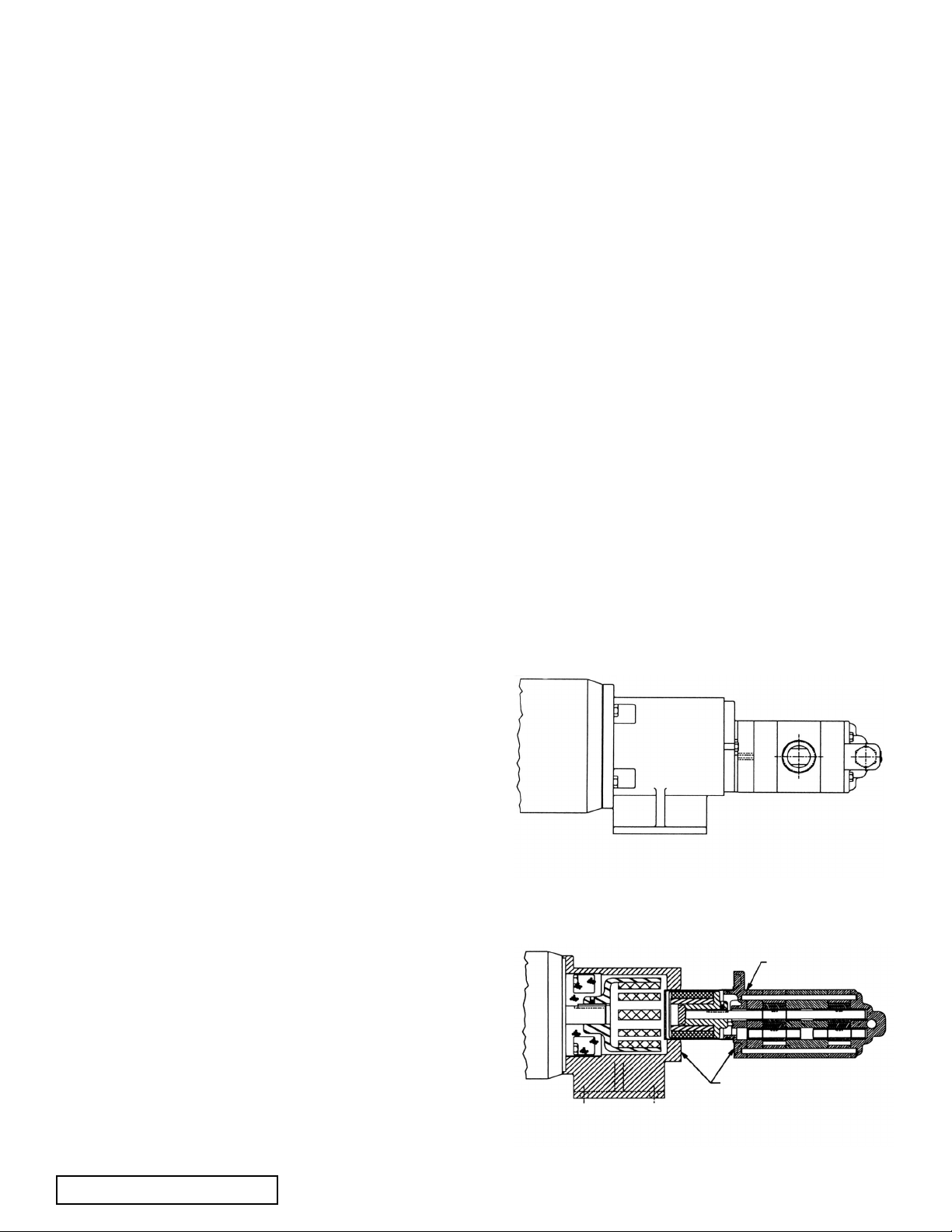
FIGURE 5
RP-80732 - MD-B15 with motor
PLACE HANDS BACK HERE
CAUTION: DO NOT PLACE FINGERS
HERE AT ANY TIME
FIGURE 6
Typical Pump Removal from Coupling Bracket
4. Arbor press
disassembly of the coupling and/or pump. Remove
for installation of a new Teflon®
bearing carrier. Loosen setscrews in outer magnet
FIGURE 5
RP-80732 - MD-B15 with motor
PLACE HANDS BACK HERE
CAUTION: DO NOT PLACE FINGERS
FIGURE 6
2. Check Pump alignment (See page 3).
3. Check piping to be sure there is no strain on the pump
casing.
4. Rotate the pump shaft by hand to be sure it turns freely.
55. Motor has been jogged and is running in the correct
direction. Refer to "General" on page 2.
6. Pressure relief valve is installed properly.
7. Suction piping is connected and tight, and valves are
open.
8. Make sure discharge piping is connected and tight,
valves are open and, and end of shaft is below liquid
level.
9. All guards are in place.
10. The above checklist is a general guideline to be used
prior to starting pump. Since Viking pump cannot foresee
every application for our product and possible system
design, final responsibility is with the user. The pump
must be utilized within the catalog specifications and the
pump system must be designed to provide safe working
conditions.
Push the "start" button. Pump should begin to deliver liquid
within 15 seconds!
If the pump does not deliver liquid, push the stop button. Do
not run the pump without liquid flow longer than 30
seconds because pump or coupling could be damaged
or ruined.
Review steps just outlined. Consider what suction and
discharge gauges indicate. If everything appears in order, put
more liquid in the pump suction port. See item 6 on page 3.
Push the start button. If nothing happens within 30 seconds,
stop the pump. The pump is not a compressor and will not
build up much air pressure. It may be necessary to vent the
discharge line until liquid begins to flow. Use a safe venting
procedure especially when handling hazardous liquids.
If the pump still does not deliver liquid, consider one or more
of the following:
1. Suction line air leaks; vacuum gauge reading should help
determine if this is the problem.
2. End of suction pipe not submerged deep enough in liquid.
3. Suction lift is too great or suction piping is too small.
4. Liquid is vaporizing in the suction line before it gets to the
pump.
5. Magnetic coupling is decoupling for some reason.
If after consideration of these points, the pump still does not
deliver liquid, review all points given under START UP and
read through the TROUBLESHOOTING guide and try again.
If pump still will not deliver liquid, contact your Viking Pump
supplier.
SUGGESTED REPAIR TOOLS: The following are required
to properly repair a RP Series Mag Drive pump. The tools are
in addition to standard mechanics tools such as open end
wrenches, pliers, screw drivers, etc. Most of the items can be
obtained from an industrial supply house.
1. Soft face hammer
2. Allen wrenches
4. Arbor press
5. Torque wrench
DISASSEMBLY OF MD-A2, MD-A8,
MD-B15, or MD-B40 COUPLINGS
1.
Read all of the instructions before proceeding with
disassembly of the coupling and/or pump. Remove
piping to ports and remove the mounting capscrews
securing pump to bracket. Support larger pumps with
overhead hoist if possible. Remove pump from coupling
bracket. See FIGURE 6 on page 4.
2. Canister will probably be full of liquid, use care while
removing from pump and pull straight off. Loosen both
setscrews and pull off inner magnet assembly. MD-A2
and MD-A8 couplings require removing the pipe plug in
pump bracket to gain access to the setscrews holding
the inner magnet.
Don't forget this is a very powerful magnet. Do not
remove O-ring on bracket unless you plan to replace -
especially the encapsulated O-rings. Follow instructions
in ASSEMBLY
for installation of a new Teflon®
encapsulated O-ring.
3. You should be able to visually inspect other magnets
from end of bracket. If removal is necessary, start by
removing (4) capscrews and separating from motor or
bearing carrier. Loosen setscrews in outer magnet
assembly to pull assembly off shaft.
FIGURE 5
RP-80732 - MD-B15 with motor
PLACE HANDS BACK HERE
CAUTION: DO NOT PLACE FINGERS
HERE AT ANY TIME
FIGURE 6
Typical Pump Removal from Coupling Bracket
3. Check piping to be sure there is no strain on the pump
casing.
4. Rotate the pump shaft by hand to be sure it turns freely.
55. Motor has been jogged and is running in the correct
direction. Refer to "General" on page 2.
6. Pressure relief valve is installed properly.
7. Suction piping is connected and tight, and valves are
open.
8. Make sure discharge piping is connected and tight,
valves are open and, and end of shaft is below liquid
level.
9. All guards are in place.
10. The above checklist is a general guideline to be used
prior to starting pump. Since Viking pump cannot foresee
every application for our product and possible system
design, final responsibility is with the user. The pump
must be utilized within the catalog specifications and the
pump system must be designed to provide safe working
conditions.
Push the "start" button. Pump should begin to deliver liquid
within 15 seconds!
If the pump does not deliver liquid, push the stop button. Do
not run the pump without liquid flow longer than 30
seconds because pump or coupling could be damaged
or ruined.
discharge gauges indicate. If everything appears in order, put
more liquid in the pump suction port. See item 6 on page 3.
Push the start button. If nothing happens within 30 seconds,
stop the pump. The pump is not a compressor and will not
build up much air pressure. It may be necessary to vent the
discharge line until liquid begins to flow. Use a safe venting
procedure especially when handling hazardous liquids.
If the pump still does not deliver liquid, consider one or more
of the following:
1. Suction line air leaks; vacuum gauge reading should help
determine if this is the problem.
2. End of suction pipe not submerged deep enough in liquid.
3. Suction lift is too great or suction piping is too small.
4. Liquid is vaporizing in the suction line before it gets to the
pump.
5. Magnetic coupling is decoupling for some reason.
If after consideration of these points, the pump still does not
deliver liquid, review all points given under START UP and
read through the TROUBLESHOOTING guide and try again.
If pump still will not deliver liquid, contact your Viking Pump
supplier.
SUGGESTED REPAIR TOOLS: The following are required
to properly repair a RP Series Mag Drive pump. The tools are
in addition to standard mechanics tools such as open end
wrenches, pliers, screw drivers, etc. Most of the items can be
obtained from an industrial supply house.
1. Soft face hammer
2. Allen wrenches
TSM 343.1 ISSUE D PAGE 4 OF 13
3. Internal snap ring pliers (for bearing carriers only) 2-810-
029-047-999 (Truarc No. 0500)
4. External snap ring pliers 2-810-029-375 (Truarc No. 0400)
5.
5. Torque wrench
6.
DISASSEMBLY OF MD-A2, MD-A8,
MD-B15, or MD-B40 COUPLINGS
1. Read all of the instructions before proceeding with
piping to ports and remove the mounting capscrews
securing pump to bracket. Support larger pumps with
overhead hoist if possible. Remove pump from coupling
bracket. See FIGURE 6 on page 4.
2. Canister will probably be full of liquid, use care while
removing from pump and pull straight off. Loosen both
setscrews and pull off inner magnet assembly. MD-A2
and MD-A8 couplings require removing the pipe plug in
pump bracket to gain access to the setscrews holding
the inner magnet.
Don't forget this is a very powerful magnet. Do not
remove O-ring on bracket unless you plan to replace especially the encapsulated O-rings. Follow instructions
in ASSEMBLY
encapsulated O-ring.
3. You should be able to visually inspect other magnets
from end of bracket. If removal is necessary, start by
removing (4) capscrews and separating from motor or
assembly to pull assembly off shaft.
Typical Pump Removal from Coupling Bracket
HERE AT ANY TIME
 Loading...