

Viking Pump TSM341.1 User Manual
Electronic copies of the most current TSM issue can be found on the Viking Pump website at www.vikingpump.com
TECHNICAL SERVICE MANUAL
MAGNETIC DRIVE - CAST IRON & DUCTILE IRON PUMPS
CONTENTS
Introduction .......................................................................... 1
Safety Information & Instructions..........................................2
Special Information .............................................................. 3
Health Concerns .................................................................. 3
Installation ........................................................................... 3
Start Up ............................................................................... 5
Maintenance ........................................................................ 5
MD-A & MD-B Coupling Pump Removal ............................. 7
SG-804, -805 & -807 Pump Disassembly............................ 9
SG-804, -805 & -807 Pump Assembly................................. 9
MD-A & MD-B Coupling Assembly .................................... 10
MD2-B & MD2-C Coupling Pump Removal ....................... 11
SG-810 & SG-814 Pump Disassembly.............................. 12
MD2-B Coupling Disassembly ........................................... 14
MD2-C Coupling Disassembly........................................... 14
SG-810 & SG-814 Pump Assembly................................... 14
Installation of Carbon Graphite Bushings .......................... 14
Assembly of Coupling - Series MD2-B & MD2-C .............. 14
MD2-B Bearing Carrier Assembly...................................... 15
MD2-C Bearing Carrier Assembly ..................................... 15
Pressure Relief Valve Instructions ..................................... 16
Troubleshooting ................................................................. 16
Do’s and Don’ts ................................................................. 17
Maintenance ...................................................................... 18
Warranty ............................................................................ 19
SECTION TSM 341.1
PAGE 1 Of 19
SERIES SG & SGN
SIZES 804, 805, 807, 810 & 814
ISSUE J
MODEL NUMBER CHART:
UNMOUNTED PUMP UNITS
CAST IRON DUCTILE IRON
SG-80417 SG-80418 SG-80425 SG-80435 SG-80450 SG-80470 -
SG-80518 SGN-80518
SG-80525 SGN-80525
SG-80535 SGN-80535
SG-80550 SGN-80550
SG-80570 SGN-80570
SG-80510 SGN-80510
SG-80514 SGN-80514
SG-80519 SGN-80519
SG-80528 SGN-80528
SG-80741 SGN-80741
SG-80758 SGN-80758
SG-80782 SGN-80782
SG-80711 SGN-80711
SG-80716 SGN-80716
SG-80722 SGN-80722
SG-80732 SGN-80732
SG-81009 SG-81013 SG-81026 -
SG-81420 SG-81436 SG-81456 -
Units are designated by the
unmounted pump model
number followed by the
magnetic coupling size and
letter indicating the drive style
provided.
D - Direct Drive
M - Motor Mounted (Close
Coupled C-Flange)
B - Bearing Carrier Mounted
R - Viking Reducer Drive
P - Commercial Reducer
Drive
(
Example: SG-80514-MD-A4 B
)
FIGURE 1
SG-80514 MD-A4M
Motor Direct Connected To Footless Bracket & Pump
FIGURE 2
SG-80711 MD-A9B & Mounted Pump
(Counterclockwise Rotation Shaft)
VIKING PUMP, INC. • A Unit of IDEX Corporation • Cedar Falls, IA 50613 USA
INTRODUCTION
The illustrations used in this manual are for identification
purposes only and cannot be used for ordering parts. Due
to the nature of the pump and the close manufacturing
tolerances, certain replacement parts are only available in
assemblies. Instructions given are for replacing the pump or
coupling parts, or entire pumping unit. Always give name of
part, model and serial number of the pump when ordering
repair parts. The pump model and serial number can be found
on the nameplate secured to the pump. In the Viking model
number system, the first number “8” indicates a magnetically
coupled design. The next two numbers determine the series
size and the last two numbers indicate the gear length. SG
Series pumps have cast iron construction. SGN pumps
feature ductile iron external construction.
This manual deals with Model SG-804, SG-805 & SG-807
pumps mounting on the magnetic drive MD-A4, MD-A9,
MD-B15 and MD-B40 couplings, as well as Model SG-810
& SG-814 pumps mounting on the magnetic drive MD2-B &
MD2-C couplings. Refer to Figures 1 through 26 for general
configuration and nomenclature used in this manual. Pump
specifications and recommendations are listed in Catalog
Section 341.3.
SAFETY INFORMATION AND INSTRUCTIONS
IMPROPER INSTALLATION, OPERATION OR MAINTENANCE OF PUMP MAY CAUSE SERIOUS INJURY
OR DEATH AND/OR RESULT IN DAMAGE TO PUMP AND/OR OTHER EQUIPMENT. VIKING’S WARRANTY
DOES NOT COVER FAILURE DUE TO IMPROPER INSTALLATION, OPERATION OR MAINTENANCE.
THIS INFORMATION MUST BE FULLY READ BEFORE BEGINNING INSTALLATION, OPERATION OR
MAINTENANCE OF PUMP AND MUST BE KEPT WITH PUMP. PUMP MUST BE INSTALLED, OPERATED
AND MAINTAINED ONLY BY SUITABLY TRAINED AND QUALIFIED PERSONS.
THE FOLLOWING SAFETY INSTRUCTIONS MUST BE FOLLOWED AND ADHERED TO AT ALL TIMES.
Symbol
Legend :
!
!
!
!
!
WARNING
!
WARNING
Danger - Failure to follow the indicated
instruction may result in serious injury
!
or death.
BEFORE opening any liquid chamber (pumping
chamber, reservoir, relief valve adjusting cap fitting,
etc.) be sure that :
● Any pressure in the chamber has been completely
vented through the suction or discharge lines or
other appropriate openings or connections.
● The pump drive system means (motor, turbine,
engine, etc.) has been “locked out” or otherwise
been made non-operational so that it cannot be
started while work is being done on the pump.
● You know what material the pump has been
handling, have obtained a material safety data
sheet (MSDS) for the material, and understand
and follow all precautions appropriate for the safe
handling of the material.
BEFORE operating the pump, be sure all drive guards
are in place.
DO NOT operate pump if the suction or discharge
piping is not connected.
DO NOT place fingers into the pumping chamber or
its connection ports or into any part of the drive train
if there is any possibility of the pump shafts being
rotated.
DO NOT exceed the pump’s rated pressure, speed,
temperature, or change the system/duty parameters
from those the pump was originally supplied, without
confirming its suitability for the new service.
BEFORE operating the pump, be sure that:
● It is clean and free from debris
● all valves in the suction and discharge pipelines
are fully opened.
● All piping connected to the pump is fully supported
and correctly aligned with the pump.
● Pump rotation is correct for the desired direction
of flow.
WARNING
WARNING
!
WARNING
!
!
!
WARNING
!
WARNING
Warning - In addition to possible serious
injury or death, failure to follow the
indicated instruction may cause damage
to pump and/or other equipment.
INSTALL pressure gauges/sensors next to the
pump suction and discharge connections to monitor
pressures.
USE extreme caution when lifting the pump. Suitable
lifting devices should be used when appropriate. Lifting
eyes installed on the pump must be used only to lift
the pump, not the pump with drive and/or base plate.
If the pump is mounted on a base plate, the base plate
must be used for all lifting purposes. If slings are used
for lifting, they must be safely and securely attached.
For weight of the pump alone (which does not include
the drive and/or base plate) refer to the Viking Pump
product catalog.
DO NOT attempt to dismantle a pressure relief valve
that has not had the spring pressure relieved or is
mounted on a pump that is operating.
AVOID contact with hot areas of the pump and/or
drive. Certain operating conditions, temperature
control devices (jackets, heat-tracing, etc.), improper
installation, improper operation, and improper
maintenance can all cause high temperatures on the
pump and/or drive.
THE PUMP must be provided with pressure protection.
This may be provided through a relief valve mounted
directly on the pump, an in-line pressure relief valve,
a torque limiting device, or a rupture disk. If pump
rotation may be reversed during operation, pressure
protection must be provided on both sides of pump.
Relief valve adjusting screw caps must always point
towards suction side of the pump. If pump rotation is
reversed, position of the relief valve must be changed.
Pressure relief valves cannot be used to control pump
flow or regulate discharge pressure. For additional
information, refer to Viking Pump’s Technical Service
Manual TSM 000 and Engineering Service Bulletin
ESB-31.
THE PUMP must be installed in a matter that allows
safe access for routine maintenance and for inspection
during operation to check for leakage and monitor
pump operation.
SECTION TSM 341.1 ISSUE J PAGE 2 OF 19
SGN - 81013 - M 0 V U
Spur Gear Principle
Frame Size Pump Size
Seal Type:
8 = Mag Drive
Material of Construction:
Blank = Cast Iron
N = Ductile Iron
(-805,-807)
DANGER !
Before opening any Viking pump liquid
chamber (pumping chamber, reservoir, relief
valve adjusting cap fitting etc.) Be sure:
1. That any pressure in the chamber has
been completely vented through the
suction or discharge lines or other
appropriate openings or connections.
2. That the driving means (motor, turbine,
engine, etc.) has been “locked out” or
made non- operational so that it cannot
be started while work is being done on
pump.
3. That you know what liquid the pump
has been handling and the precautions
necessary to safely handle the liquid.
Obtain a material safety data sheet
(MSDS) for the liquid to be sure these
precautions are understood.
Failure to follow above listed precautionary
measures may result in serious injury or
death.
SPECIAL INFORMATION
ROTATION: Viking Mag Drive® pumps are designed to
run in a designated direction (indicated on name plate).
Shaft rotation determines which port is suction and which is
discharge. Running the pump in the opposite direction may
seriously affect the performance of the unit and the relief
valve (if present) will not operate. If rotation must be reversed,
contact your Viking Pump supplier for instructions and parts
to change over.
1. A pressure relief valve is mounted as standard on the
SG/SGN series magnetically coupled pumps.
2. The SG/SGN series is a positive displacement pump
and requires some form of over pressure protection.
Without pressure protection, if the discharge line is
blocked or becomes closed, pressure will build up until
the motor stalls, drive equipment fails, a pump part
breaks, or the piping and/or other equipment in the
system bursts.This may be an integral pressure relief
valve supplied with the pump, a torque limiting device
or a rupture disk.
Design Series Bracket:
Shaft Rotation:
(Viewed from shaft end)
0 = Clockwise
1 = Counter-Clockwise
3. Do not use decoupling of magnets as protection from
over pressure. SG/SGN Series pumps can develop
potentially damaging pressure before the magnets
decouple. Decoupling of the magnets may also cause
damage to the magnets themselves.
4. The relief valve adjusting screw cap must always point
toward suction side of pump.
5. Pressure relief valves cannot be used to control flow or
regulate pressure.
For additional information on pressure relief valves. Refer to
Technical Service Manual TSM000 and Engineering Service
Bulletin ESB-31.
M = Metric (ISO) Bracket for
IEC Motor Mount (-10,-14)
U = SAE Bracket for
NEMA Motor Mount (-10,-14)
Relief Valve:
O = Without Valve
V = With Valve
(Single Pumps only)
CAUTION !
Rare earth magnets used in these couplings
have extremely strong magnetic fields capable of changing the performance or damaging
items such as the following:
• Pacemakers
• Metal implants
• Watches
• Computers and discs
• Credit cards
Completely assembled magnetic couplings
will not affect the items listed above.
Altered performance or damage can occur
only when the coupling halves are separated.
There are no known harmful effects of these
magnetic fields on the human body itself.
INSTALLATION
General
The following items must be considered prior to pump
installation:
1. Location - locate the pump as close as possible to
supply of liquid being pumped. If possible locate the
pump below liquid supply. Viking pumps are self priming;
but, the better the suction conditions the better the pump
will perform.
2. Accessibility - pump must be accessible for inspection,
maintenance and repair.
SECTION TSM 341.1 ISSUE J PAGE 3 OF 19
General Cont’d
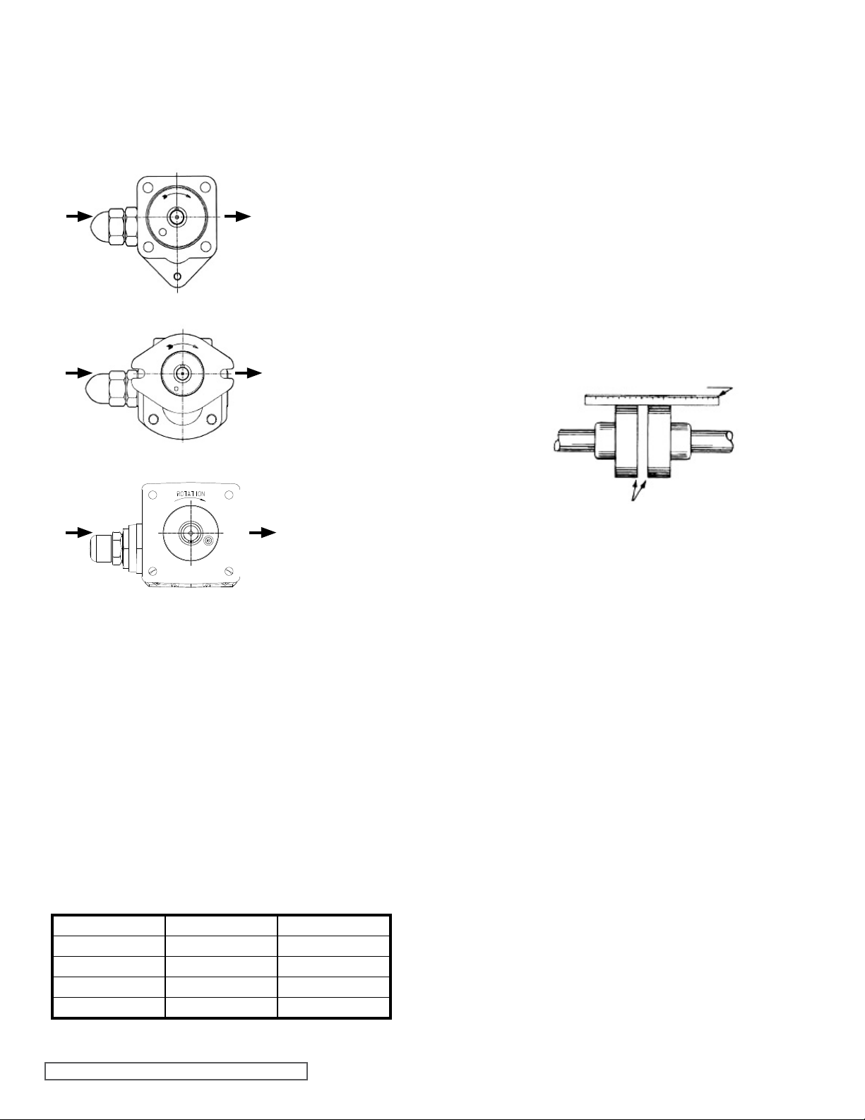
3. Suction/Discharge - SG/SGN Series pumps are designed
for clockwise rotation as standard (viewed from end
of shaft). Refer to Figure 3, Figure 4 and Figure 5.
Always check rotation arrow on nameplate before
mounting and start-up.
S D
FIGURE 3
Clockwise Rotation
of 804 & 805
(Viewed From Shaft End)
3. Do not strike or press the inner magnet coupling half
to install on the pump shaft. Damage to the pump or
coupling may result if the coupling does not slide onto
pump shaft, inspect the coupling bore, shaft and key for
nicks or burrs and remove if present.
4. Once the pump has been mounted, place a small
amount of compatible liquid into the suction port and turn
by hand to ensure the pump turns freely.
Alignment
Check alignment after mounting on units with a bearing
carrier.
1. If the unit has a flexible coupling, remove any coupling
guards or covers and check alignment of the coupling
halves. A straight edge (piece of key stock will work)
across the coupling must rest evenly on both rims at the
top, bottom and sides. See Figure 6.
2. Make final check of alignment after the piping is hooked
up. Replace the guards.
S
S
D
FIGURE 4
Clockwise Rotation
of 807
(Viewed From Shaft End)
D
FIGURE 5
Clockwise Rotation
of 810 & 814
(Viewed From Shaft End)
Mounting
When using an M drive configuration, alignment is insured
by the coupling bracket. If the unit features a bearing carrier,
then a flexible coupling will be required and care should be
given to properly align the bearing carrier to the motor. See
“Alignment” on this page.
Since the magnetic coupling is integral to the mounting of
the pump, more specific information is presented under
the ASSEMBLY and DISASSEMBLY sections presented
elsewhere.
1. Pump mounting surface and canister outer surface must
be clean and free of metal particles.
2. Mounting capscrews must be torqued evenly. See
TABLE 1 below for recommended torque value.
FT-LBs: Nm:
804 12-15 16-20
805 12-15 16-20
807 31-34 42-46
810 50-65 68-88
814 50-65 68-88
TABLE 1
USE STRAIGHT EDGE. THESE SURFACES MUST BE PARALLEL
COUPLING
ALIGNMENT
CHECK WIDTH BETWEEN THESE
SURFACES WITH INSIDE CALIPERS TO BE
CERTAIN THE FACES ARE EQUAL DISTANCE
APART AND PARALLEL
FIGURE 6
Piping/Hose
The cause of many pumping problems can be traced to
suction piping. It should always be as large in diameter and
as short in length as possible.
Before starting the layout and installation of your piping
system, consider the following points:
1. Never use piping smaller than the pump port connections.
Piping larger in diameter than the port connection is
sometimes is required to reduce suction losses.
2. Be sure the inside of the pipe is clean before installing.
3. When approaching an obstacle in the suction line, go
around instead of over it. Going over obstacle creates an
air pocket. Where practical slope the piping so no air or
liquid pockets will be formed. Air pockets in the suction
line make it hard for the pump to prime.
4. A strainer on the suction side of the pump should always
be considered in any pumping system. The strainer will
keep foreign matter from entering the pump. The strainer
mesh or perforation size should be as fine as possible
to protect the pump without causing excessive pressure
drop. Use of a strainer is particularly important at start up
to help clean the system of weld beads, pipe scale and
other foreign objects.
5. A pressure relief valve is required in the discharge line.
See Pressure Relief Valves, SPECIAL INFORMATION,
page 3.
6. Pump must not be used to support piping. The weight of
the pipe must be carried by hangers, supports, stands,
etc.
SECTION TSM 341.1 ISSUE J PAGE 4 OF 19

7. When fastening the piping to the pump, it should not
be necessary to impose any strain on pump casing.
“Springing” or “drawing” piping up to the pump will cause
distortion, possible misalignment and probable rapid
wear of the pump. Do not use pump to correct errors in
piping layout or assembly.
8. All joints of piping system must be tight; liquid thread
sealant will help assure leak free threaded joints. Loose
joints result in liquid leaks or suction side leaks. Air leaks
make the pump noisy and reduce flow. CAUTION: Be
careful not to over tighten fittings as this can cause
cracked joints. Do not use PTFE / plumber’s tape.
Reduced friction makes over tightening very easy and
will result in cracked ports.
9. Drive alignment must be checked after the piping is
hooked up.
10. Provide a pressure relief device if any part of a pump
and piping system that can be valved off, thus completely
isolated. A rise in temperature will cause liquid to expand.
With no provision for pressure relief in the closed off
section, there is a chance that the pump or piping will
rupture.
START UP
Before pushing the “start” button, check the following:
1. Vacuum and pressure gauges (liquid filled) are mounted
on or near the pump. Gauges are the quickest and most
accurate way of finding out what is happening in the
pump.
2. The pump is correctly aligned.
3. There is no pipe strain on the pump.
4. Pump turns freely by hand. If the unit features a bearing
carrier then rotate the flexible coupling, but if the unit is
motor mounted then carefully try to turn the motor fan
blades to turn the pump over.
5. The motor has been jogged and is running in the correct
direction. Refer to “General” page 4 item 3.
6. A pressure relief valve is installed properly.
7. The suction piping is connected and tight, and the valves
are open.
8. The discharge piping is connected and tight, the valves
are open and there is a place for liquid to go.
9. All guards are in place.
The above checklist is a general guideline to be used prior to
starting the pump. Since Viking Pump cannot foresee every
application for our product and possible system design, final
responsibility is with the user. The pump must be utilized
within the catalog specifications and the pump system must
be designed to provide safe working conditions.
Push the “start” button. The pump should begin to deliver
liquid within 15 seconds!
If the pump does not deliver liquid, push the stop button. Do
not run the pump without liquid flow longer than 30 seconds
because the pump or coupling could be damaged or ruined.
Review steps just outlined. Consider what the suction and
discharge gauges indicate. Since the pump will not develop
much pressure when filled with air, it may be necessary to
vent the discharge line until liquid begins to flow.
Reprime the pump and push the “start” button again. If the
pump still does not deliver liquid, consider one or more of the
following:
1. Suction line air leaks.
2. The end of the suction pipe is not submerged deep
enough in liquid.
3. Suction lift is too great or suction piping is too long.
4. Liquid is vaporizing in the suction line before it gets to
the pump.
5. Magnetic coupling is decoupling for some reason.
If after consideration of these points, the pump still does not
deliver liquid, review all points given under START UP and
read through the TROUBLESHOOTING guide (page 16)
and try again. If pump still will not deliver liquid, contact your
Viking Pump supplier.
MAINTENANCE
CLEANING UNIT: Keep the pump, coupling and motor as
clean as possible. This will facilitate inspection, adjustment
and repair work.
STORAGE: If the pump or coupling are to be stored, drain
pump and pour non-detergent SAE 30 weight oil into pump
port. Apply grease to pump or coupling shaft extension, if
present or accessible. Viking suggests rotating the pump
shaft every 30 days to circulate the oil in the pump. The pump
and coupling should be stored in a dry area. Note: if the liquid
to be pumped reacts with oil, use an acceptable alternate.
SUGGESTED REPAIR TOOLS: The following are required
to properly repair a SG/SGN Series Mag Drive pump. The
tools are in addition to standard mechanics tools such as
open end wrenches, pliers, screw drivers, etc. Most of the
items can be obtained from an industrial supply house.
1. Soft face hammer
2. Allen wrenches
3. Internal snap ring pliers (for bearing carriers only)
2-810-029-047-999
4. External snap ring pliers 2-810-029-375
5. Arbor press
6. Torque wrench
DANGER !
Before starting pump, be sure all drive
equipment guards are in place.
Failure to properly mount guards may result in
serious injury or death.
SECTION TSM 341.1 ISSUE J PAGE 5 OF 19

MAGNETIC COUPLING BRACKET
CANISTER
OUTER MAGNET ASSEMBLY
INNER MAGNET ASSEMBLY
SHAFT KEY
CANISTER O-RING
PUMP BRACKET HOLLOW DRIVE SHAFT
DRIVE GEAR
BUSHING
CASING
RETAINING RINGS
ALIGNMENT PIN
DRIVEN GEAR
FIGURE 7
Cutaway View Mag-Drive Pump, Model SG-81026 MD2-B32
FIGURE 8
Coupling Exploded View
ITEM DESCRIPTION ITEM DESCRIPTION ITEM DESCRIPTION
Setscrews, Outer Magnets -
1
(2 Req’d)
Outer Magnet Assembly - (3 Bore Sizes)
2
Bracket, Footed or Footless
3
Capscrew for Motor or B.C.
4
(4 Req’d)
Canister
5
Inner Magnet Assembly - (2 Bore
6
Sizes)
Hex Nut - (4 Req’d)
7
Lock Washer - (4 Req’d)
8
Bearing Housing
9
Retaining Ring, External (2 Req’d)
10
Bearing Housing
11
Ball Bearing (2 Req’d)
12
Retaining Ring, Internal
13
Key (2 Req’d)
14
Shaft
15
TABLE 2
SECTION TSM 341.1 ISSUE J PAGE 6 OF 19
 Loading...