

Viking Pump TSM280 User Manual
INSTALLATION, OPERATION
AND
MAINTENANCE MANUAL
FOR THE
VIKING PUMP, INC. A Unit of IDEX Corporation
Cedar Falls, Iowa 50613 U.S.A.
Issue B - Jun 03

INSTALLATION, OPERATION AND MAINTENANCE MANUAL
FOR DURALOBE® ROTARY LOBE PUMPS.
1.0 SAFETY INFORMATION. _______________________________________ 3
RISK ASSESSMENT RELATING TO THE USE OF VIKING PUMP DURALOBE ROTARY LOBE
PUMPS AND PUMP UNITS IN POTENTIALLY EXPLOSIVE ATMOSPHERES
. ______________ 6
2.0 INTRODUCTION. ______________________________________________ 7
2.1 GENERAL. ___________________________________________________ 7
2.2 VIKING PUMP DISTRIBUTORS. _____________________________________ 7
2.3 RECEIPT AND STORAGE._________________________________________ 7
2.4 CLEANING. __________________________________________________ 8
2.5 PUMP MODEL DESIGNATION. _____________________________________ 8
2.5.1 A
2.5.2 E
TEX INFORMATION PLATE _____________________________________ 9
QUIPMENT GROUPS & CATERGORIES_____________________________ 9
2.6 PUMP MODEL AND SERIAL NUMBER. _______________________________ 10
2.7 STANDARD PUMP COMPONENT TERMS._____________________________ 11
3.0 GENERAL. __________________________________________________ 12
3.1 DURALOBE
3.2 DURALOBE
®
PUMPING PRINCIPLE._________________________________ 12
®
PUMP OPERATING PARAMETERS. ________________________ 13
3.3 SYSTEM DESIGN. _____________________________________________ 14
3.3.1 SYSTEM DESIGN AND INSTALLATION. _____________________________ 14
3.3.2 INSTALLATIONS WITH CIP SYSTEMS. _____________________________ 16
3.4 START UP PROCEDURE.________________________________________ 16
3.6 ROUTINE MAINTENANCE. _______________________________________ 18
3.7 HEATING AND COOLING DEVICES _________________________________ 18
3.8 INTEGRAL PRESSURE RELIEF VALVES ______________________________ 21
3.8.1 SETTING AND OPERATING SPRING LOADED VALVES __________________ 22
3.8.2 SETTING AND OPERATING AIR LOADED VALVE ______________________ 23
4.0 DURALOBE® PUMP DISMANTLING AND ASSEMBLY. ______________ 30
4.1 DISASSEMBLY._______________________________________________ 31
4.1.2 C
ARTRIDGE REMOVAL _______________________________________ 33
4.1.3 CARTRIDGE DISASSEMBLY ____________________________________ 34
4.2 ASSEMBLY. _________________________________________________ 35
4.2.1 C
ARTRIDGE ASSEMBLY _______________________________________ 35
4.2.2 CARTRIDGE TO ROTORCASE ASSEMBLY___________________________ 39
4.2.3 ROTOR ASSEMBLY AND SETTING ROTOR CLEARANCES________________ 41
4.2.4 GEARBOX COVER ASSEMBLY __________________________________ 43
4.3 PRODUCT SEAL FITTING AND REMOVAL. ____________________________ 44
4.3.1 GENERAL PROCEDURES FOR FITTING MECHANICAL SEALS._____________ 44
4.3.2 SINGLE MECHANICAL SEAL ____________________________________ 45
4.3.3 SINGLE FLUSHED MECHANICAL SEAL_____________________________ 47
4.3.4 DOUBLE MECHANICAL SEAL ___________________________________ 49
4.3.5
4.3.6 D
SINGLE O-RING SEAL________________________________________ 51
OUBLE O-RING SEAL _______________________________________ 52
4.3.7 TRAPPED SLEEVE___________________________________________ 53
4.3.8 HYBRID DOUBLE MECHANICAL 2000 SEAL _________________________ 54
Page : 1

4.3.9 HYBRID DOUBLE MECHANICAL SEAL _____________________________ 55
4.3.10 HYBRID SINGLE FLUSHED MECHANICAL SEAL_______________________ 56
4.3.11 STRIP CLEAN SINGLE O-RING SEAL ______________________________ 57
4.3.12 DURALOBE SINGLE O-RING SEAL OL1____________________________ 58
4.3.13 DURALOBE SINGLE O-RING SEAL S2, S3, S4_______________________ 59
4.3.14 MK2 DOUBLE O-RING SEAL S1_________________________________ 60
4.3.15 MK2 DOUBLE O-RING SEAL S2, S3, S4 __________________________ 61
4.3.16 FLUSHED PRODUCT SEAL _____________________________________ 62
5.0 SPECIFICATIONS.____________________________________________ 65
5.1 CLEARANCE CHART ___________________________________________ 65
5.2 FASTENERS & TORQUE SETTINGS. ________________________________ 66
5.3 L
5.4
UBRICANTS ________________________________________________ 67
MATERIAL SPECIFICATION. ________________________________________ 67
Page : 2
1.0 Safety Information.
WARNING
INCORRECT INSTALLATION, OPERATION OR MAINTENANCE OF
EQUIPMENT MAY CAUSE SEVERE PERSONAL INJURY OR DEATH
AND/OR EQUIPMENT DAMAGE AND MAY INVALIDATE THE WARRANTY.
THIS INFORMATION MUST BE READ FULLY BEFORE BEGINNING
INSTALLATION, OPERATION OR MAINTENANCE AND MUST BE KEPT
WITH THE PUMP. ALL INSTALLATION AND MAINTENANCE MUST BE
UNDERTAKEN BY SUITABLY TRAINED OR QUALIFIED PERSONS ONLY.
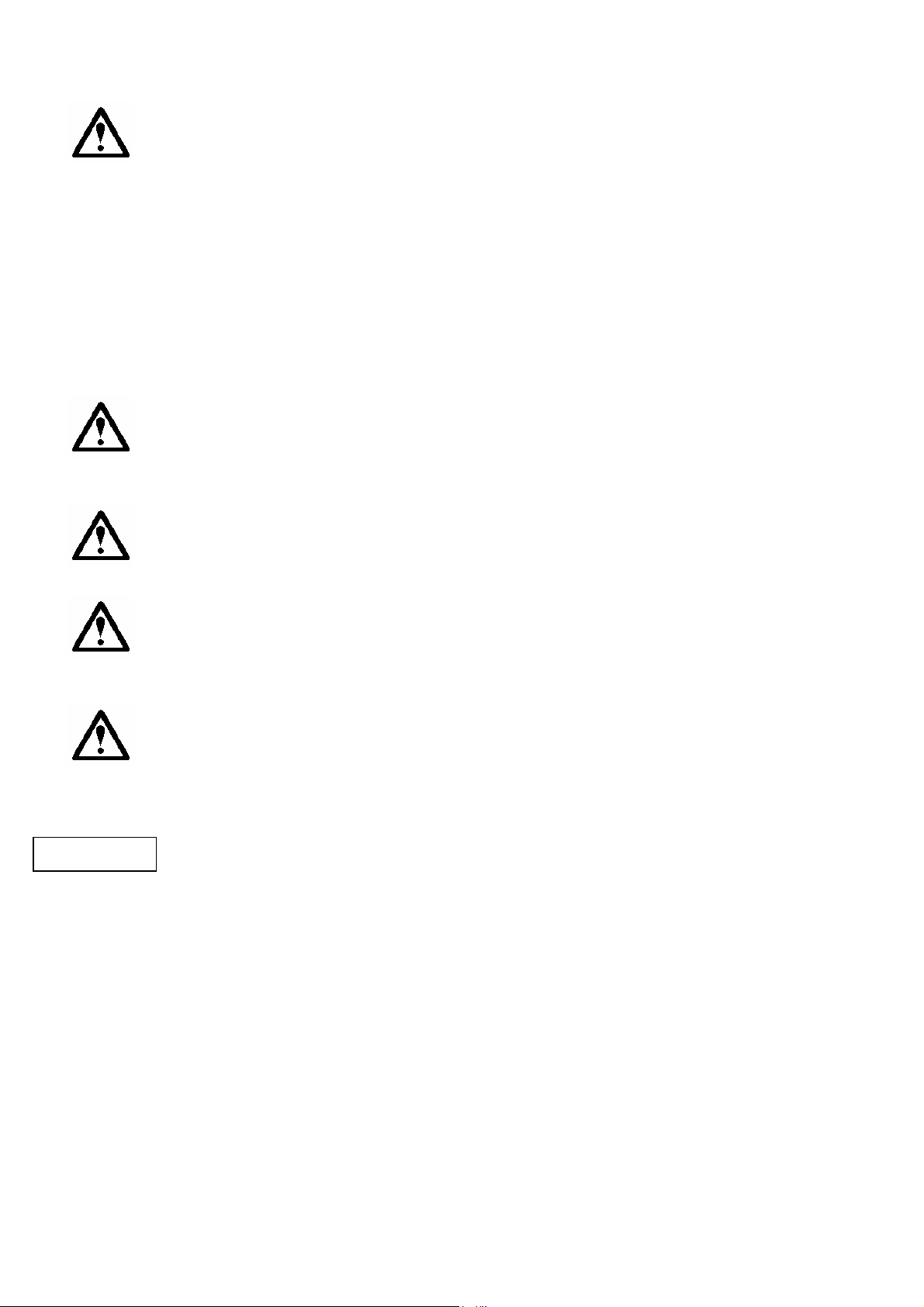
Danger - Failure to follow the listed
precautionary measures may result
in serious injury or death are
identified by the following symbol:
Warning - Safety instructions which
shall be considered for reasons of safe
operation of the pump or pump unit
and/or protection of the pump or pump
unit itself are marked by the sign:
WARNING
DANGER
DO NOT OPERATE PUMP IF :
- The front cover is not installed correctly.
- Any guards are missing or incorrectly installed.
- The suction or discharge piping is not connected.
DO NOT place fingers, etc. into the pumping chamber or its connection ports
or into any part of the gearbox if there is ANY possibility of the pump shafts
being rotated. Severe injury will occur.
DO NOT exceed the pumps rated pressure, speed, and temperature, or
change the system/duty parameters from those for which the pump was
originally supplied, without confirming its suitability for the new duty. Running
the pump outside of its operating envelope can cause mechanical contact in
the pump head, excessive heat and can represent a serious risk to health and
safety.
Installation and operation of the pump must always comply with health and
safety regulations.
A device must be incorporated into the pump, system, or drive to prevent the
pump exceeding its stated duty pressure. It must be suitable for both
directions of pump rotation where applicable. Do not allow pump to operate
with a closed/blocked discharge unless a pressure relief device is
incorporated. If an integral relief valve is incorporated into the pump, do not
allow re-circulation through the relief valve for extended periods, (refer to
section 3.8).
Page : 3
The mounting of the pump or pump unit should be solid and stable.
WARNING
WARNING
WARNING
WARNING
WARNING
Pump orientation must be considered in relation to drainage
requirements. Once mounted, shaft drive elements must be checked
for correct alignment. Rotate pump shaft by at least one full revolution
to ensure smoothness of operation. Incorrect alignment will produce
excessive loadings and will create high temperatures and increased
noise emissions. Do not use any drive arrangements which cause side
loading of the drive shaft. It may also be necessary to earth the pump
to avoid the build up of a potential charge difference that could cause a
spark.
The installation must allow safe routine maintenance and inspection (to
replenish lubricants, check for leakage, monitor pressures, etc) and provide
adequate ventilation necessary to prevent overheating.
Fill all gearboxes with the recommended grades and quantities of lubricant,
(refer to section 3.4). Beware of over / under filling the gearbox as this could
cause the pump to over heat and mechanical damage to occur.
Before operating the pump, be sure that it and all parts of the system to which
it is connected are clean and free from debris and that all valves in the suction
and discharge pipelines are fully opened. Ensure that all piping connecting to
the pump is fully supported and correctly aligned with its relevant connections.
Misalignment and/or excess loads will cause severe pump damage. This
could result in unexpected mechanical contact in the pump head and has the
potential to be a source of ignition.
Be sure that pump rotation is correct for the desired direction of flow, (refer to
section 3.4).
Do not install the pump into a system where it will run dry (i.e. without a
supply of pumped media) unless it is equipped with a flushed shaft seal
arrangement complete with a fully operational flushing system. Mechanical
seals require a thin fluid film to lubricate the seal faces. Dry running can cause
excessive heat and seal failure.
Pressure gauges/sensors are recommended, next to the pump suction and
discharge connections to monitor pressures.
Caution must be taken when lifting the pump. Suitable lifting devices should
be used as appropriate. Lifting eyes installed on the pump must only be used
to lift the pump, not pump with drive and/or base plate. If pump is base plate
mounted, the base plate must be used for all lifting purposes. If slings are
used for lifting, they must be safely and securely attached. For weights of bare
shaft pumps refer to section 5.5.
Page : 4
DO NOT attempt to dismantle a pressure relief valve which has not
WARNING
DO NOT attempt any maintenance or disassembly of the pump or pump unit
without first ensuring that :
- The pump is fully isolated from the power source (electric, hydraulic,
pneumatic).
- The pumping chamber, pneumatic relief valve and any shaft seal
support system are depressurized and purged.
- Any temperature control devices (jackets, heat-tracing, etc) are fully
isolated, that they are depressurized and purged, and components are
allowed to reach a safe handling temperature.
had the spring pressure relieved, is still connected to a pressurized
gas/air supply or is mounted on a pump that is operating. Serious
personal injury or death and/or pump damage may occur.
DO NOT loosen or undo the front cover, any connections to the pump, shaft
seal housings, temperature control devices, or other components, until sure
that such action will not allow the unsafe escape of any pressurized media.
Pumps and/or drives can produce sound power levels exceeding 85 dB(A)
under certain operating conditions. When necessary, personal protection
against noise must be taken. Typical noise emission data can be found in
section 5.8.
Avoid any contact with hot parts of pumps and/or drives which may cause
injury. Certain operating conditions, temperature control devices (jackets,
heat-tracing, etc.), bad installation, or poor maintenance can all promote high
temperatures on pumps and/or drives.
When cleaning, either manually or by CIP method, the operator must ensure
that a suitable procedure is used in accordance with the system requirements.
During a CIP cleaning cycle, a pump differential pressure of between 30 and
45 psi is recommended to ensure suitable velocities are reached within the
pump head. The exterior of the pump should be cleaned periodically.
Page : 5

Risk assessment relating to the use of Viking Pump Duralobe rotary lobe pumps and
p
g
g
y
p
pump units in potentially explosive atmospheres.
Note:- For a feature to be suitable for an application, The feature must be fit for its
designated purpose and also suitable for the environment where it is to be installed.
Source Of Hazards Potential Hazards
Unvented cavities Build up of explosive gas
Rotorcase / Rotors / Front
Cover
Pump external surfaces
Cover 'O' ring
Pump casing / cover
Shaft seals
Auxiliary system for shaft
sealing
Rotation direction test Excess temperature
Closed valve condition
Shaft Random induced current
Mechanical shaft coupling
(Torque Protection)
Mechanical shaft coupling
(standard)
Unintended mechanical
contact
excess temperature.
Electrostatic charging
Pump liquid leakage. Build
up of explosive gas.
Pump liquid leakage. Build
up of explosive
excess temperature.
Unintended mechanical
contact.
Leakage.
Build up of explosive
Pump liquid leakage. Build
up of explosive gas.
Excess Temperature.
Excess Pressure.
Mechanical contact.
Temperature from friction
Sparks from break up of
shear pins.
Electrostatic charging
Break up of spider.
Unintended mechanical
contact.
Electrostatic charging
as.
as.
Frequency Of
Hazards
Very Rare
Rare
Rare
Very Rare
Very Rare
Rare
Rare
Very Rare
Rare
Very Rare
Rare
Rare
Recommended Measures
Ensure that pump is totally filled.
Consider mounting ports vertically.
See Chapter 1.0
Ensure that operating pressures are
not exceeded. Ensure that suffcient
NPSH to prevent cavitation.
Chapter 1.0/3.3.1
User must ensure temperature limits.
Do not overfill gearboxes with
lubricant. Provide a ground contact
for pump.
Check selection of elastomers are
suitable for application. Ensure cover
retaining nuts are tight. Service plan.
Stainless steel, Corrosion resistant.
Selection of seal system must be
suitable for application.
5.0
Selection of auxiliary seal system
must be suitable for application.
Mechanical seals must never run
If flushed seals are installed ensure
assemblys. Only allow pump to run
for minimum period - just a few
Can cause excessive pressue, heat
Provide a ground contact for pump.
See Chapter 1.0 /
. Service plan. Mechanical seals
must never run dry
that flush is applied to seal
seconds.
and mechanical contact.
Cha
See Chapter 1.0.
Coupling selection must suit
application.
Coupling selection must suit
application. Service plan.
Chapter 1.0.
Service plan.
lan.
.
dr
ter 1.0
See Chapter 1.0.
See
Service
See Chapter
See
See
Page : 6

2.0 Introduction.
2.1 General.
Duralobe® rotary lobe pumps are manufactured by Johnson Pump (UK)
a unit of Viking Pump Inc., Cedar Falls, USA, herein after referred to as
Viking Pump.
This manual includes all the necessary information for Duralobe
®
pumps and should be read prior to beginning installation, operation or
maintenance.
Should you require any additional information regarding the Duralobe®
pumps contact Viking Pump or their local authorized distributor, refer to
section 2.2.
When asking for assistance please provide the pump model and serial
number. This information can be obtained from the pump nameplate
which is located on the side of the pump gearbox cover, refer to section
2.6.
Should the nameplate be unreadable or missing, the pump serial
number is also stamped on either side of the rotorcase, refer to section
2.6.
If the system or product characteristics are to be changed from the
original application for which the pump was selected, Viking Pump or
their authorized distributor should be consulted to ensure the pump is
suitable for the new application.
2.2 Viking Pump Distributors.
Viking Pump distributes it’s products internationally via a network of
authorized distributors. Throughout this manual where reference is
made to Viking Pump, service and assistance will also be provided by
any Viking Pump authorized distributor for Duralobe® pumps.
2.3 Receipt and Storage.
Upon receipt of the pump, immediately examine it for any signs of
visible damage. If any damage is noted, contact Viking Pump or your
Viking Pump distributor and clearly mark upon the carriers paperwork
that the goods have been received in a damaged condition, with a brief
description of damage.
If the pump is not required for immediate installation then it should be
stored in a clean, dry environment. It is recommended that storage
temperature should be between 14°F and 105°F.
Page : 7

2.4 Cleaning.
The Duralobe® pump series is suitable for both manual cleaning and
CIP (Cleaning In Place), refer to section 3.3.2.
The product seals are mounted directly behind the rotors and are
designed and positioned to minimize product entrapment and maximize
the effects of cleaning.
This strategic positioning of the product seals, combined with their ease
of access provides an arrangement that can be more effectively
cleaned by both manual and CIP procedures.
It is recommended that the exterior of the pump is cleaned periodically.
2.5 Pump Model Designation.
The designation of pump models are as follows:
S1S S3S
S1M S3M
S1L S3L
S2S S4S
S2M S4M
S2L S4L
This information, together with the pump serial number, should be
provided when requesting additional information on the pump or when
ordering spare parts. The pump serial number is stamped on the pump
nameplate and the rotorcase, (refer to section 2.6, Figs 2 and 3).
For the maximum operating pressures, temperatures and speeds refer
to section 3.2, Fig 6.
Page : 8
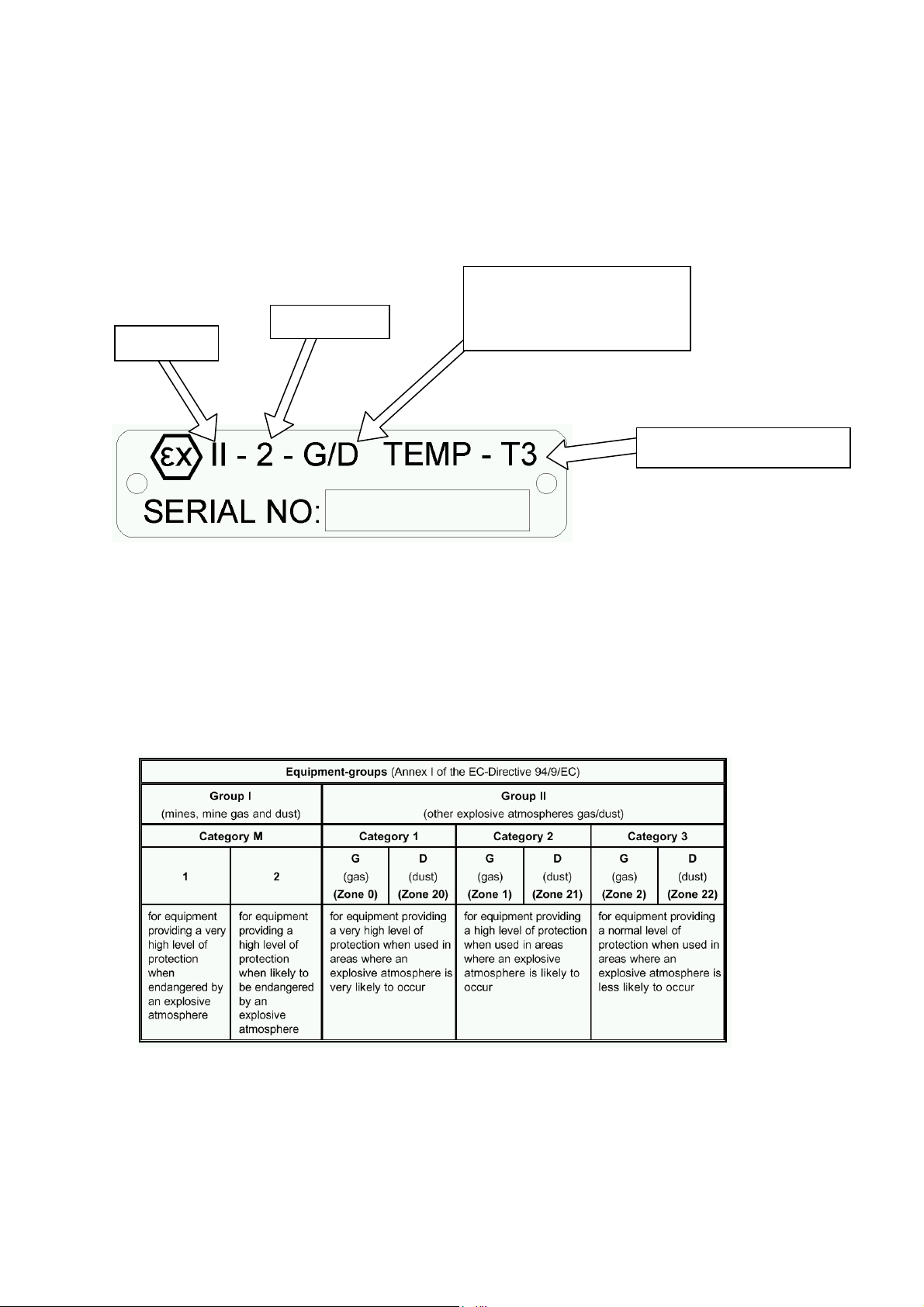
2.5.1 Atex Information Plate
Category 2
Group II.
2.5.2 Equipment Groups & Catergories
Unit is suitable for
environments containing
dust or gas
Temperature Class.
Page : 9
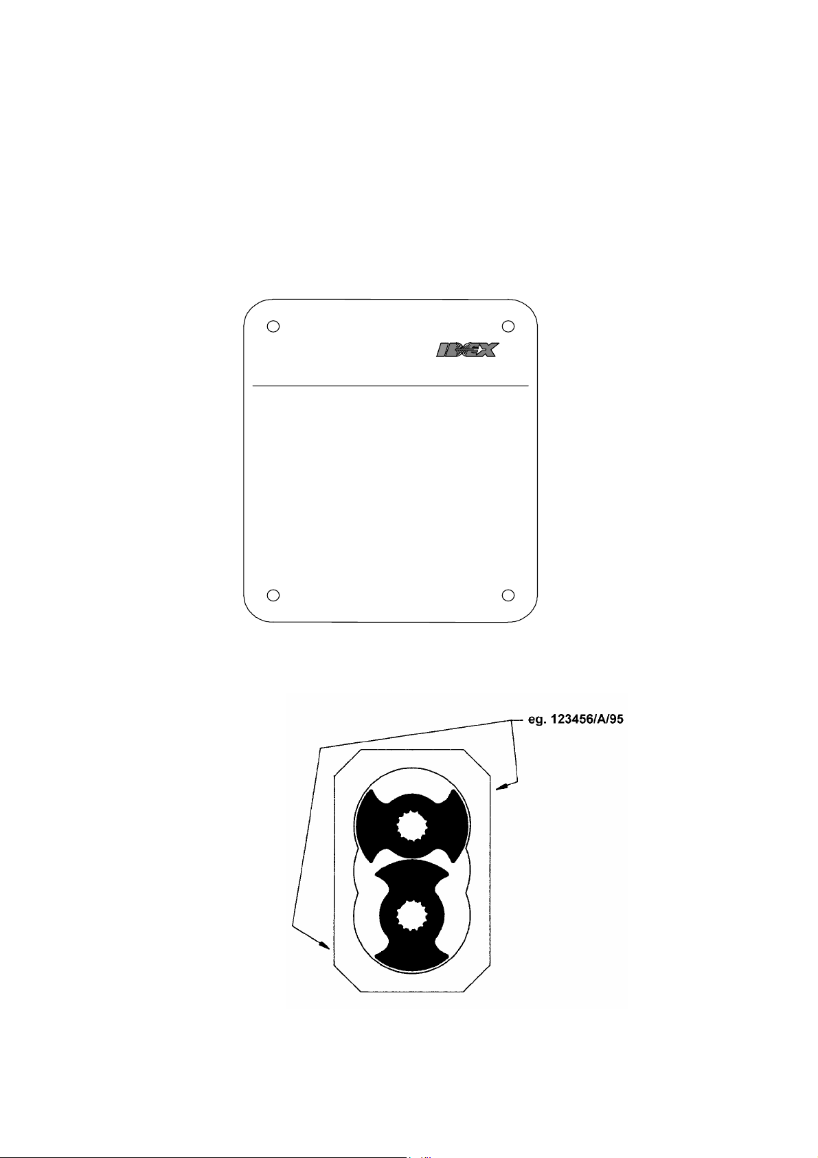
2.6 Pump Model and Serial Number.
V
Should you require any information regarding your Duralobe® rotary
lobe pump contact Viking Pump or your Viking Pump distributor,
providing the pump model and serial number as stated on the pump
nameplate, see Fig 2, which is fixed to the pump gearbox cover.
Should this be damaged or missing, the pump serial number is also
stamped on opposite corners of the rotorcase, (see Fig 3).
Fig 2
IKING
PUMP
IDEX CORP ORATION
MODEL
FI LL TO SI GHT LEVEL
RECOMMENDED LUBRICANT
SERI AL NUMBER
BUILD CODE
MADE IN GREAT BRI TAIN
A Uni t of I DEX Cor po r a t i onVI KI NG PUMP I NC.
USACEDAR FALLS , I A
Fig 3
Page : 10

2.7 Standard Pump Component Terms.
Fig 4
Page : 11
3.0 General.
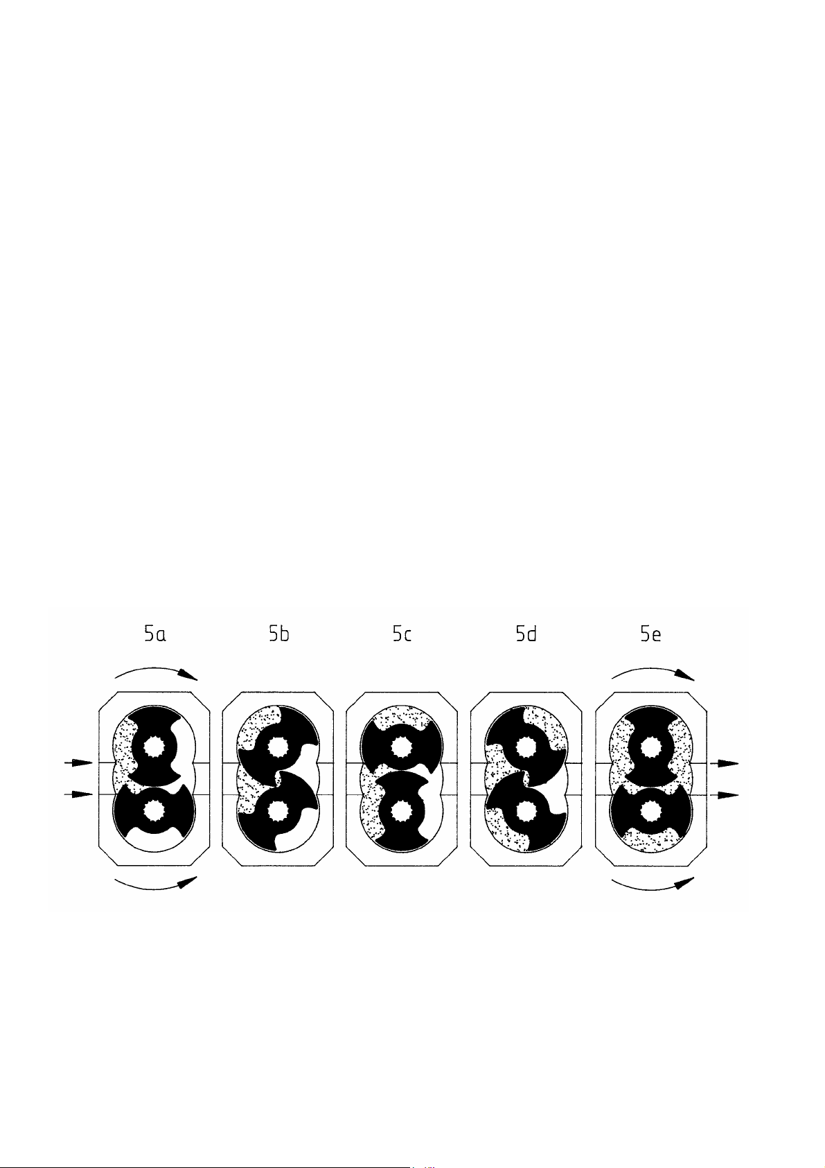
3.1 Duralobe® Pumping Principle.
The pumping action of the rotary lobe pump principle is generated by the
contra-rotation of two pumping elements (rotors) within a chamber (rotorcase),
see Fig 5. The rotors are located on shafts which in turn are held within two
cartridges mounted onto the back of the rotorcase. The shaft cartridge
assemblies comprise of, the shaft support bearings and the timing gears. The
gears transfer the energy from the drive shaft to the driven shaft,
synchronizing the rotors such that they rotate without contact with each other.
As the rotors pass the suction port, Fig 5a, the cavity increases creating a
pressure decrease, which induces the pumped medium to flow into the
rotorcase.
The pumped medium is carried around the rotorcase by the rotors, Fig 5b and
5c, to the discharge side of the pump, Fig 5d. Here the cavity decreases and
the pumped medium is discharged from the rotorcase, Fig 5e.
For pump component terms see Fig 4.
Fig 5 Rotary Lobe Pump Principle.
Page : 12

3.2 Duralobe® Pump Operating Parameters.
Fig 6
Pump
Series
Theoretical Displacement
Liter /
rev
Imp.gal
/100 rev
US gal
/100
rev
Nominal
Connection
Size
Max Diff.
Pressure
Maximum
Speed
Max
Temp
Max
Temp
mm inches bar psi rev/min °C °F
S1S 0.04 0.88 1.06 25 1 14 200 1150 150 300
S1M 0.06 1.32 1.59 25 1 10 150 1150 150 300
S1L 0.08 1.76 2.11 25 1 7 100 1150 150 300
S2S 0.17 3.74 4.49 38 1.5 14 200 1150 150 300
S2M 0.25 5.50 6.61 50 2 10 150 1150 150 300
S2L 0.34 7.48 8.98 50 2 7 100 1150 150 300
S3S 0.54 11.88 14.27 50 2 14 200 870 150 300
S3M 0.81 17.82 21.40 76 3 10 150 870 150 300
S3L 1.08 23.76 28.53 76 3 7 100 870 150 300
S4S 1.62 35.64 42.80 76 3 14 200 700 150 300
S4M 2.43 53.46 64.20 101 4 10 150 700 150 300
S4L 3.24 71.28 85.60 101 4 7 100 700 150 300
The maximum pressure and speed operating parameters are given in Fig 6.
In practice these may be limited due to the nature of the product to be
pumped and/or design of the system in which the pump is to be installed.
Consult Viking Pump or your Viking Pump distributor for assistance.
If the system or product characteristics are to be changed from the
WARNING
original application for which the pump was selected, Viking Pump or
their authorized distributor should be consulted to ensure the pump is
suitable for the new application.
The pump should not be subjected to sudden temperature changes to avoid
the risk of damage from sudden expansion/contraction of components. Care
should be taken when selecting pumps for handling liquids containing
abrasive particles as these may cause wear of pump head components. For
advice or assistance contact Viking Pump or your Viking Pump distributor.
Page : 13
3.3 System Design.
3.3.1 System Design and Installation.
i) Be sure ample room is provided around the pump to allow for:
a) Access to the pump and drive for routine inspection and
b) Ventilation of the drive to prevent over heating.
WARNING
ii) The pump must not be used to support piping. All piping to and from
iii) Valves should be provided adjacent to the pump suction and discharge
iv) Rotary lobe pumps are of the positive displacement type and therefore
a) A pressure relief valve integral with the pump where available and
b) An in-line pressure relief system, i.e. external to the pump.
c) Incorporation of a torque limiting device in the drive system.
d) Rupture disc incorporated in the discharge piping.
When incorporating any pump into a system it is considered good practice to
minimize piping runs and the number of pipe fittings (tees, unions, bends etc.)
and restrictions. Particular care should be taken in designing the suction line,
which should be as short and straight as possible with a minimum of pipe
fittings to minimize restricting product flow to the pump. The following should
be considered at the design stage of any system:
maintenance, i.e. to replenish pump or drive lubricant or to
remove pump front cover and rotors.
the pump unit must be independently supported. Failure to observe
this may distort the pump head components or assembly and cause
serious consequential damage to the pump.
connections to allow the pump to be isolated from the system for
routine inspection and maintenance.
an overload protection device must be provided. This can take the form
of:
suited to the application, refer to section 3.8.
Where pump rotation and hence flow is to be reversed during normal
operation, the overload device must be capable of protection for both
directions of rotation/flow. The Duralobe® integral relief valves are described
in section 3.8 and are designed to operate under such conditions.
Page : 14
WARNING
v) It is recommended that all piping and associated equipment from the
vi) Pressure gauges should be installed adjacent to the pump suction and
WARNING
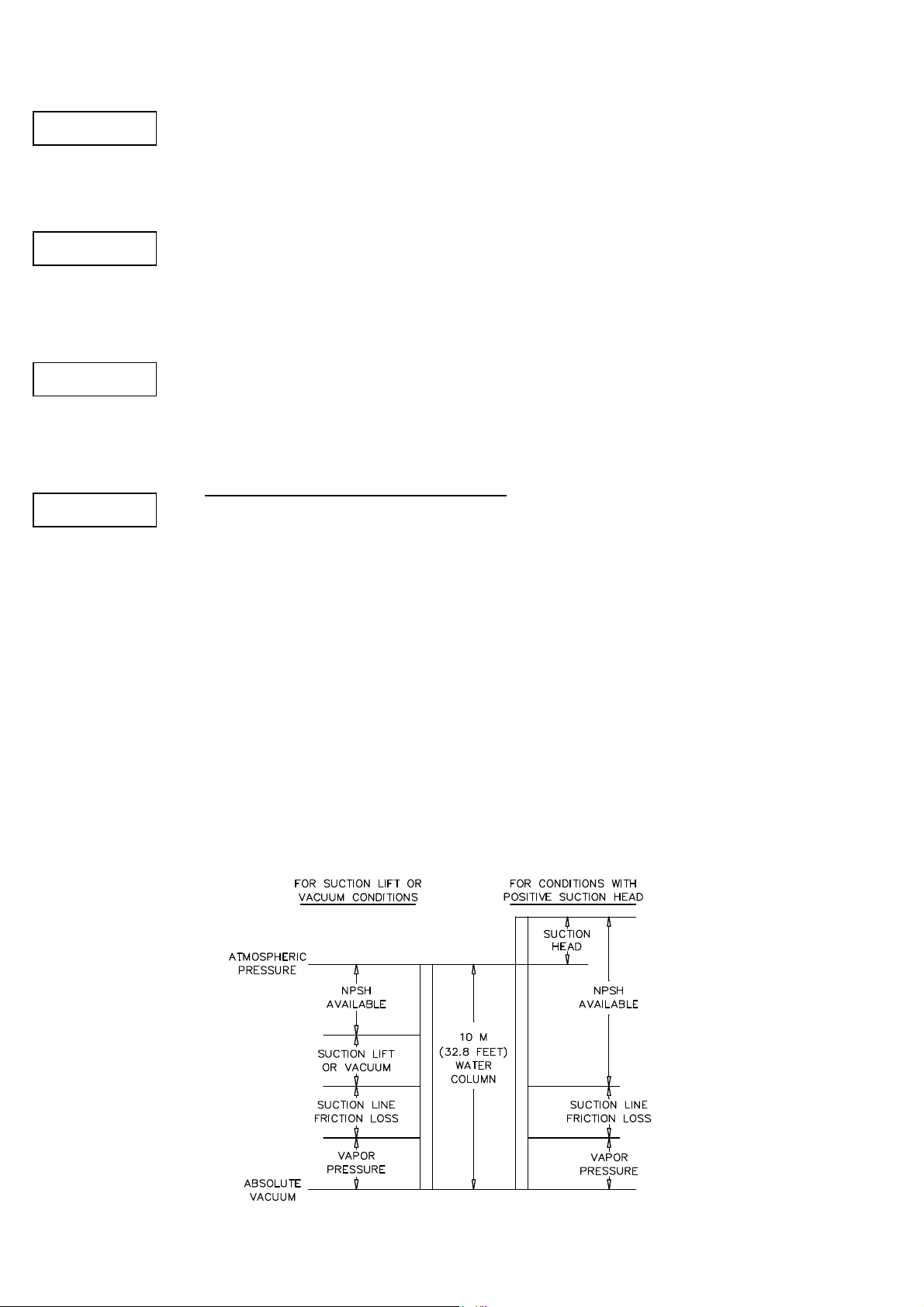
vii) It is imperative that the suction condition at the pump inlet meets the
WARNING
WARNING
tank to the discharge point is thoroughly cleaned before installation of
the pump to avoid the possibility of debris entering the pump and
causing damage.
discharge connections such that system pressures can be monitored.
These gauges will provide a clear indication of changes in operating
conditions and where a relief valve is incorporated in the system, will
be necessary for setting and checking the functioning of the valve.
Net Positive Suction Head Required (NPSHr) by the pump. Failure to
observe this could cause cavitation, resulting in noisy operation,
reduction in flow rate and mechanical damage to the pump and
associated equipment.
The Net Positive Suction Head Available
(NPSHa) from the system must
always exceed the Net Positive Suction Head Required (NPSHr) by the pump.
Observing the following general guidelines should ensure the best possible
suction condition is created.
- Suction piping is at least the same diameter as the pump connections.
- The length of suction piping is kept to the absolute minimum.
- The minimum number of bends, tees and pipework restrictions are
used.
- That calculations to determine system NPSHa are carried out for the
worst condition, see Fig 7.
Should advice on pump or system NPSH characteristics be required contact
Viking Pump or your Viking Pump distributor.
Fig 7
Page : 15

(viii) When installing a pump complete with baseplate, motor and drive the
a) The preferred drive arrangement for any rotary lobe pump is in-line direct
b) Flexible couplings must always be incorporated and correctly aligned within
Couplings of a non flexible design must never be used.
c) Couplings must always be enclosed in a suitable guard to prevent contact with
d) When installing pump sets in flammable or explosive environments, or for
e) Baseplates must be secured to a flat level surface such that distortion and
f) When using electric motor drives, ensure that the electrical supply is
3.3.2 Installations with CIP Systems.
The Duralobe
3.4 Start Up Procedure.
WARNING
WARNING
following guidelines must be observed:
coupled. If an alternative is required please contact Viking Pump or your
Viking Pump distributor.
the limits recommended by the coupling manufacturer. To check coupling
alignment rotate the shaft by at least one full revolution and ensure that the
shaft rotates smoothly.
rotating parts which could result in personal injury. Guards should be of
suitable material ,(see d) and of sufficiently rigid design to prevent contact
with rotating parts under normal operating conditions.
handling flammable or explosive materials, special consideration must be
given not only to the safety aspects of the drive unit enclosure but also to the
materials used for both the coupling and the guard to eliminate the risk of
explosion.
misalignment are avoided. Once baseplates are fastened in position the
drive alignment must be re-checked, (see b).
compatible with the drive and controls and that the method of wiring is
correct for the type of starting required by the motor i.e. Direct On Line, or
other similar method. Ensure all components are correctly grounded.
®
has been designed to be effectively cleaned by the CIP
procedures recommended for in place cleaning of process equipment. It is
recommended that a differential pressure of 30 to 45 psi be developed across
the pump head during cleaning in order to develop the necessary fluid
velocities required for thorough cleaning.
- Check that all piping and associated equipment are clean and free from
debris and that all pipe connections are secure and leak free.
- For pumps installed with flushed product seals check that all auxiliary
services are in place and connected and provide sufficient flow and
pressure for flushing purposes, refer to section 4.3.7.
Page : 16
WARNING
WARNING
WARNING
WARNING
Fig 8
- Ensure lubrication is provided for both pump and drive. Duralobe®
pumps are shipped without oil and should be filled to the level of the oil
sight glass which must be installed in the upper tapped hole in the side
of the gearbox cover, refer to section 5.3 for pump oil capacities and
grades.
- If an external relief valve is incorporated in the system check that it is
set correctly. For start up purposes it is considered good practice to set
the relief valve lower than the system design pressure. On completion
of start up the relief valve should be reset to the required setting for the
application. The required setting should never exceed the lower of
either the pumps maximum pressure rating or the system design
pressure. For setting integral relief valves, refer to sections 3.8.1 and
3.8.2.
- Ensure both suction and discharge valves are fully open, and pipework
is free from all obstructions. Duralobe® pumps are of the positive
displacement type and should therefore never be operated against a
closed valve as this would result in pressure overload, resulting in
damage to the pump and possibly the system.
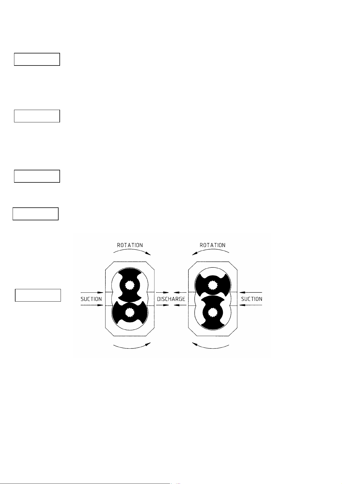
- Ensure rotation of the drive shaft is correct for the direction of flow
required, see Fig 8.
WARNING
-Before beginning operation it is considered good practice to
-Ensure product is available in the tank before starting pump. This is
very important for pumps installed with unflushed product seals as
these sealing arrangements must never be allowed to run dry.
momentarily start/stop the pump to check the direction of rotation and
ensure that the pump is free of obstructions. Once this has been
carried out, begin operation keeping a visual check on suction and
discharge pressure gauges and monitor pump temperature and power
absorbed where possible.
Page : 17
3.5 Shutdown Procedure.
When shutting the pump down close both the suction and discharge valves
- The prime mover power source has been isolated.
- If installed, the pneumatically operated integral relief valve has been
- If Installed, flushed product seal auxiliary services have been isolated
- Pump head and piping have been drained and purged.
3.6 Routine Maintenance.
WARNING
- Check oil levels regularly.
- For lubricant capacities and grades refer to section 5.3.
3.7 Heating and Cooling Devices
see Figs 9 and 10.
and ensure that the necessary safety precautions are taken:
depressurized.
and depressurized.
- Change the oil every 12 months or 3000 operating hours whichever is
the sooner.
All Duralobe® models except the S1 series, can be supplied with a jacketed
front cover and rotorcase with ports for circulation of a heating/cooling media.
The jacketed front cover and rotorcase heating and cooling ports are
strategically positioned such that the required thermal effect acts on the
pumping chamber and product seal area.
The pressure rating of the Duralobe® series jacketed front cover and
rotorcase heating/cooling ports is 50 psi and should not be exceeded without
consulting Viking Pump or your local Viking Pump distributor.
Heating/cooling of the pump head is used to maintain, rather than
increase/decrease the temperature of the pumped media and should be used
as part of a complete system where suction and discharge lines and vessels
are also heated/cooled.
Where heating/cooling devices are employed, the heating/cooling media
should be circulated 15-20 minutes prior to pump start-up and should be
allowed to continue for a similar period of time after the pump has been
shutdown. Where a CIP cycle is employed as part of the process, the
heating/cooling media should continue to be circulated during the cleaning
cycle.
Page : 18
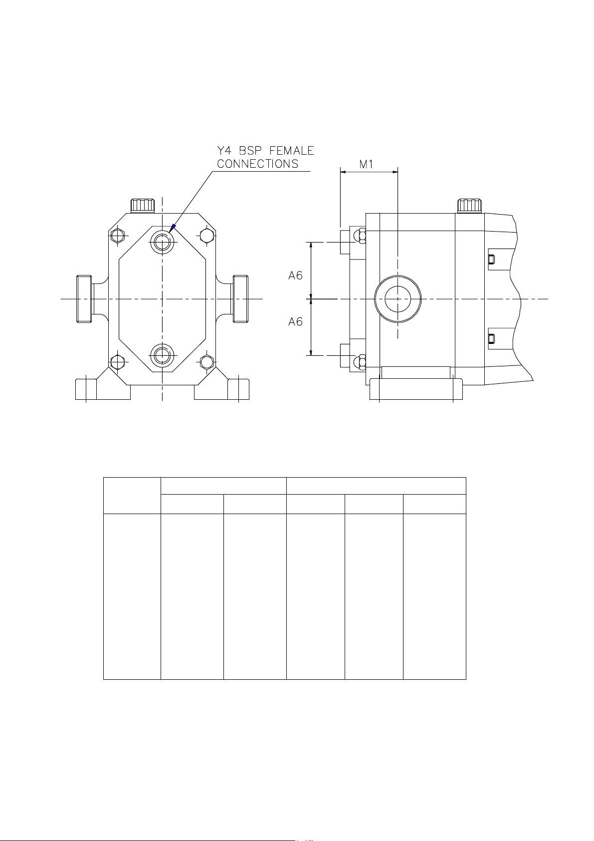
Fig 9 Dimensions of Front Cover Jacket for Heating/Cooling.
Model
S1S
S1M
S1L
S2S
S2M
S2L
S3S
S3M
S3L
S4S
S4M
S4L
Note: For all other dimensions see section 5.5, Foundation Dimensions and
Weights.
Millimeters Inches
A6 M1 A6 M1 Y4
45.0
45.0
45.0
70.0
70.0
70.0
105.0
105.0
105.0
150.0
150.0
150.0
52.0
54.0
54.5
70.0
75.0
76.0
95.0
104.0
104.0
113.0
126.0
133.0
1.77
1.77
1.77
2.76
2.76
2.76
4.13
4.13
4.13
5.91
5.91
5.91
2.05
2.13
2.15
2.76
2.95
2.99
3.74
4.09
4.09
4.45
4.96
5.24
¼
¼
¼
½
½
½
½
½
½
½
½
½
Page : 19
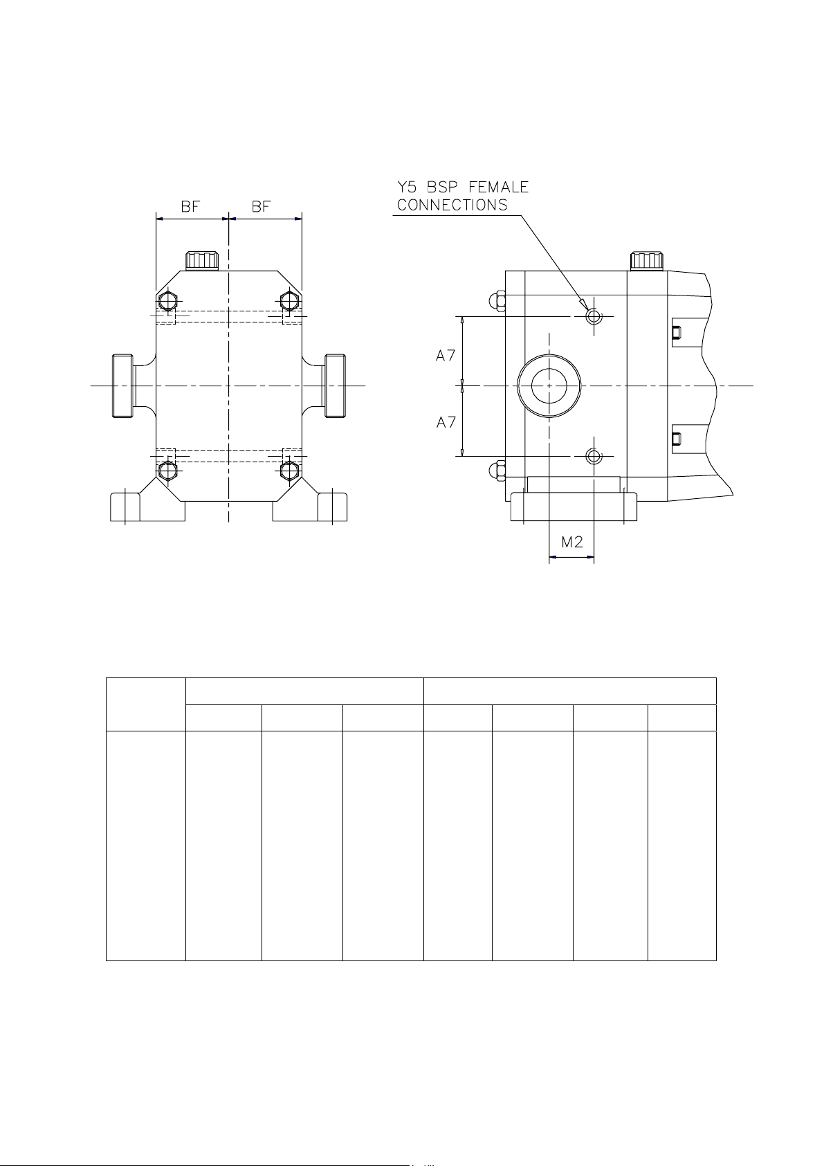
Fig 10 Dimensions for Rotorcase Ports for Heating/Cooling.
Model
S1S
S1M
S1L
S2S
S2M
S2L
S3S
S3M
S3L
S4S
S4M
S4L
Note: For all other dimensions see section 5.5, Foundation Dimensions and
Weights.
A7 BF M2 A7 BF M2 Y5
N/A
N/A
N/A
80.0
80.0
80.0
102.5
102.5
102.5
140.0
140.0
140.0
Millimeters Inches
N/A
N/A
N/A
66.5
66.5
66.5
90.5
90.5
90.5
137.0
137.0
137.0
N/A
N/A
N/A
14.0
24.5
36.0
16.0
25.0
49.0
22.0
35.0
64.0
N/A
N/A
N/A
3.15
3.15
3.15
4.04
4.04
4.04
5.51
5.51
5.51
N/A
N/A
N/A
2.62
2.62
2.62
3.56
3.56
3.56
5.39
5.39
5.39
N/A
N/A
N/A
0.55
0.96
1.42
0.63
0.98
1.93
0.87
1.38
2.52
N/A
N/A
N/A
1/8
1/8
1/8
1/8
1/8
1/8
1/8
1/8
1/8
Page : 20

3.8 Integral Pressure Relief Valves
see Figs 11, 12, 13 and 14.
All models in the Duralobe® series can be supplied with integral pressure
relief valves with both spring and air loaded versions available. The function of
the valves can be further enhanced with the option of manual or airlift override
offering particular benefits where CIP or SIP is employed. Valves
incorporating this option can be opened to regulate the volume of the cleaning
media within the pump chamber thereby avoiding the need for manual
cleaning or external by-pass.
Where the pump is mounted onto a portable cart baseplate complete with
motor and drive to be used as a mobile set, it is strongly recommended that a
integral pressure relief valve is installed.
The Duralobe® integral pressure relief valves available include:
Spring Loaded - see Fig 11.
Valve can be set to required pressure relief setting.
Spring Loaded with Manual Lift - see Fig 12.
Valve can be set to required pressure relief setting. Manual lift override can
be used to open valve without disturbing pressure relief setting (not
available on the S4 series).
Spring Loaded with Air Lift - see Fig 13.
Valve can be set to required pressure relief setting. Air lift override, which
operates on an air supply of up to 105 psi depending on pressure relief
setting, can be used to open valve without disturbing pressure relief setting
(not available on the S4 series).
Air Loaded with Air Lift - see Fig 14.
Valve, which operates on an air supply of up to 105 psi for S1, S2, S3 and
150 psi for S4, can be set to required pressure relief setting. Air lift override,
which operates on an air supply of up to 105 psi for S1,S2,S3 and 150 psi
for S4, depending on pressure relief setting, can be used to open valve
without disturbing pressure relief setting.
Air actuated relief valves can be operated remotely and interfaced with other
elements of the system or process control.
Integral pressure relief valves are normally used to protect the pump from the
effects of increases in system pressure caused, for example, by a restricted or
closed discharge line. In response to a pressure increase the valve opens
and internally circulates the pumped media within the pump chamber.
Page : 21

WARNING
3.8.1 Setting and Operating Spring Loaded Valves
see Figs 11, 12 and 13.
WARNING
- Reinstall cover (108). For integral relief valve with manual lift, see Fig 12,
WWHHEENN TTHHEE VVAALLVVEE OOPPEENNSS,, BBEECCAAUUSSEE TTHHEE VVOOLLUUMMEE OOFF FFLLUUIIDD
CCIIRRCCUULLAATTIINNGG IISS RREELLAATTIIVVEELLYY SSMMAALLLL,, TTHHEE TTEEMMPPEERRAATTUURREE OOFF TTHHEE
FFLLUUIIDD IINN TTHHEE PPUUMMPP CCHHAAMMBBEERR MMAAYY RRIISSEE IIFF TTHHEE PPUUMMPP CCOONNTTIINNUUEESS TTOO
OOPPEERRAATTEE FFOORR AANN EEXXTTEENNDDEEDD PPEERRIIOODD.. IINN SSEEVVEERREE CCAASSEESS TTHHIISS MMAAYY
RREESSUULLTT IINN TTEEMMPPEERRAATTUURREESS IINN EEXXCCEESSSS OOFF TTHHEE PPUUMMPPSS OOPPEERRAATTIINNGG
LLIIMMIITTSS OORR VVAAPPOORRIIZZAATTIIOONN OOFF TTHHEE FFLLUUIIDD,, BBOOTTHH OOFF WWHHIICCHH SSHHOOUULLDD BBEE
AAVVOOIIDDEEDD.. FFOORR TTHHEESSEE RREEAASSOONNSS WWHHEENN TTHHEE VVAALLVVEE IISS AACCTTIIVVAATTEEDD
TTHHEE CCAAUUSSEE OOFF TTHHEE SSYYSSTTEEMM PPRREESSSSUURREE IINNCCRREEAASSEE SSHHOOUULLDD BBEE
EELLIIMMIINNAATTEEDD AASS CCOONNTTIINNUUOOUUSS OOPPEERRAATTIIOONN OOFF TTHHEE PPUUMMPP WWIITTHH TTHHEE
VVAALLVVEE OOPPEENN IISS NNOOTT RREECCOOMMMMEENNDDEEDD AANNDD MMAAYY CCAAUUSSEE SSEEVVEERREE
DDAAMMAAGGEE TTOO TTHHEE PPUUMMPP..
If the pump on which the valve is installed is to be installed in either a
pressurized system or one incorporating a vessel under vacuum, the
application of the valve should be referred to Viking Pump or their authorized
distributor.
The selection, setting and application of integral relief valves is influenced by
the viscosity and nature of the pumped media, the pump operating speed and
the required pressure relief setting and mode of operation. For these reasons,
and to cover the diverse range of products, the conditions under which they
are pumped, and application demands, it is not practical to factory set integral
relief valves. The setting of the valve should be carried out on site under the
proposed duty conditions for which the pump and valve were selected.
For setting and operating Duralobe® integral relief valves refer to sections
3.8.1 and 3.8.2. Before beginning the relief valve setting procedure the pump
should be installed, refer to section 3.3.1, with a pressure gauge in the
discharge line adjacent to the pump discharge port.
- Remove cover (108). For integral relief valve with manual lift, see Fig
12, first remove nut (129) and handwheel (111).
- Loosen nut (107) using a pry bar in the holes provided, to relieve spring
compression. For integral relief valve with air lift, see Fig 13, the air
cylinder must be exhausted prior to unscrewing the nut (107).
- Start pump, refer to section 3.4.
- Screw in nut (107) using pry bar in holes provided until required
pressure relief setting is reached.
Note: Care should be taken not to exceed the lower of either the pumps
maximum pressure rating or the system design pressure.
reinstall handwheel (111) and nut (129).
Page : 22
 Loading...