

Viking Pump TSM270 User Manual
Electronic copies of the most current TSM issue can be found on the Viking Pump website at www.vikingpump.com
TECHNICAL SERVICE MANUAL
CONTENTS
Safety Information 1
Introduction 1
Special Information 4
Maintenance 4
Suggested Repair Tools 5
Disassembly 5
Cartridge Seal 6
Labyrinth Seal 7
Assembly 7
Thrust Bearing Adjustment 8
Installation of PEEK® Bushings 9
Warranty 12
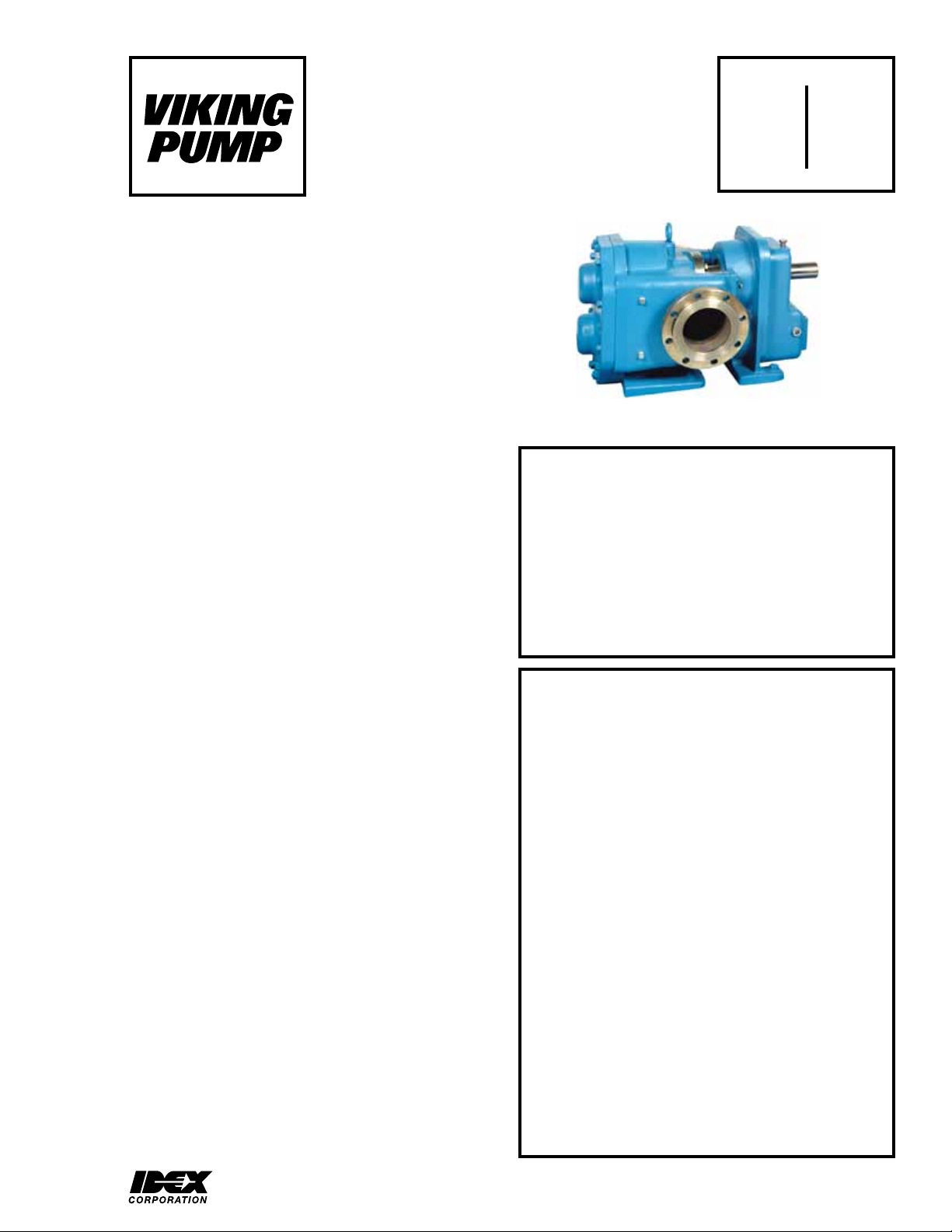
INDUSTRIAL ROTARY LOBE PUMP
MODEL RL41507
FIGURE 1
MODEL RL41507
DANGER!
Incorrect installation, operation or maintenance of
equipment may cause severe personal injury or
death and/or equipment damage.
SECTION TSM 270
PAGE 1 Of 10
ISSUE f
TABLE OF ILLUSTRATIONS
RL41507 Pump Assembly 1
Exploded Pump Parts View 2
Pump Rotation 4
Head Removal 5
Timing Gear Removal 5
Use Of Bearing Puller 6
Bracket Removal 6
Fluidtec P/S®-II Cartridge Seal 6
Lobe Positioning 7
Bearing Housing Assembly 7
Timing Gear Positioning 7
INTRODUCTION
The illustrations used in this manual are for identification
purposes only and cannot be used for ordering parts. Obtain
a parts list from the factory or a Viking representative.
Always give a complete name of part, part number and
material with the model number and serial number of pump
when ordering repair parts. The unmounted pump or pump
unit model number and serial number are on the nameplate.
This manual deals only with Viking Rotary Lobe Pumps.
Specifications and recommendations are listed in Catalog
Section 270.
This information must be read fully before beginning
installation, operation or maintenance and must be
kept with the pump. It is suggested that suitably
trained or qualified persons perform all installation
and maintenance procedures.
DANGER !
Before opening any Viking pump liquid chamber
(pumping chamber, reservoir, etc.) be sure:
1. That any pressure in the chamber has been
completely vented through the suction or
discharge lines or other appropriate openings or
connections.
2. That the driving means (motor, turbine, engine, etc.)
has been “locked out” or made non-operational so
that it cannot be started while work is being done
on pump.
3. That you know what liquid the pump has been
handling and the precautions necessary to
safely handle the liquid. Obtain a material safety
data sheet (MSDS) for the liquid to be sure these
precautions are understood.
4. That the timing gearbox to cool before handling the
pump. The oil will become very hot during normal
operation. Allow the timing gearbox oil.
PEEK® is a trademark of Victrex PLC.
VIKING PUMP, INC. • A Unit of IDEX Corporation • Cedar Falls, IA 50613 USA
Failure to follow above listed precautionary measures may result in serious injury or death.
SECTION TSM 270 ISSUE F PAGE 2 OF 10
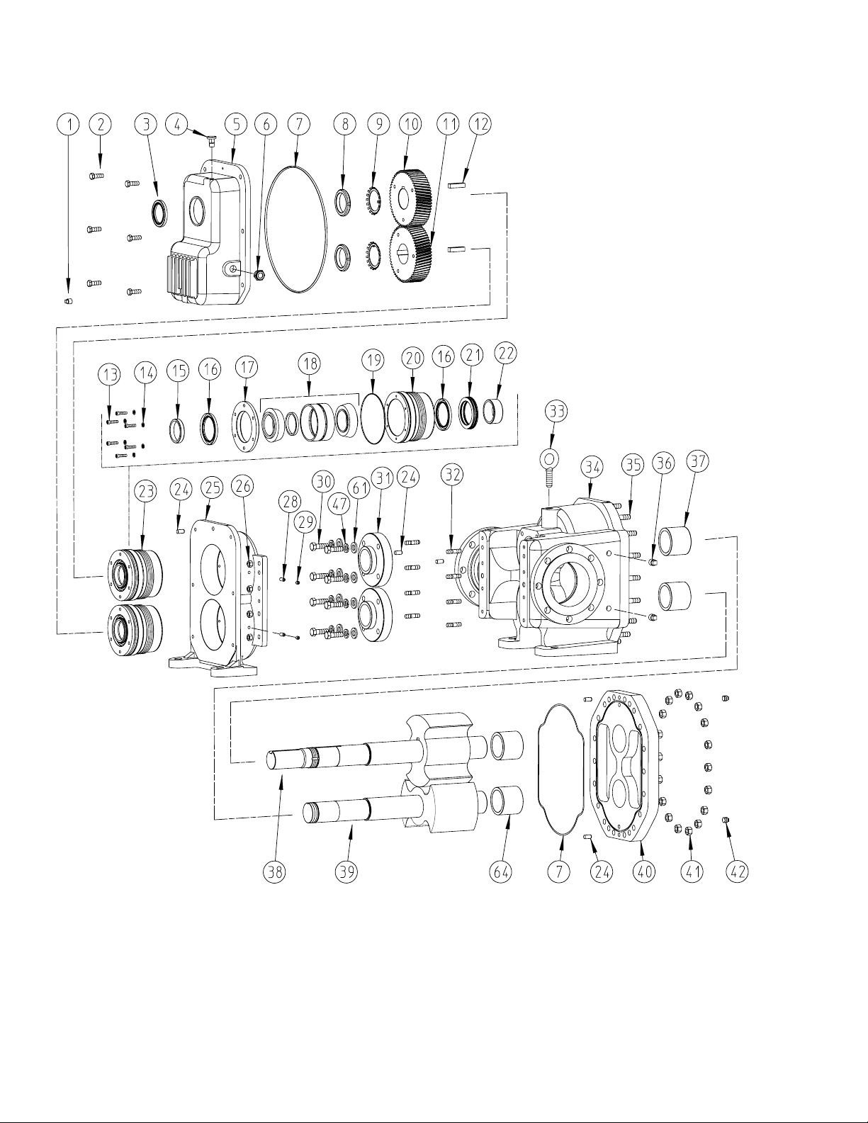
FIGURE 2 EXPLODED PARTS VIEW

TABLE 1 RL41507
ITEM DESCRIPTION ITEM DESCRIPTION
1 Magnetic Drain Plug for Gear Case 24 Dowel Pin, (5 Req’d)
2 Capscrew for Gear Cover 25 Bracket
3 Lipseal for Gear Box Cover 26 Nut 1/2” NC for Bracket, (8 Req’d)
4 Breather 28 Setscrews for Bearing Housing, (4 Req’d)
5 Gear Case Cover 29
6 Sight Glass 30 Capscrew for Seal, 5/8”, (8 Req’d)
7 Gear Case Cover or Head O-ring 31 Cartridge Lipseal, (2 Req’d)
8 Locknut TN-14, (2 Req’d) 32 1/2” Stud for Bracket, (8 Req’d)
9 Lockwasher TN-14, (2 Req’d) 33 Lifting Eye
10 Timing Gear for Driver Shaft 34 Casing/Bushing Assembly
11 Timing Gear for Driven Shaft 35 5/8” Stud for Head, (18 Req’d)
12 Key, Special 36 ½” Pipe Plugs, to Casing, (4 Req’d)
Capscrew for Bearing Housing Assembly, (12 Req’d - 6 for each
13
Bearing Housing Assembly)
Lockwasher for Bearing Housing Assembly, (12 Req’d - 6 for
14
each Bearing Housing Assembly)
Outer Bearing Spacer, (2 Req’d - 1 for each Bearing Housing
15
Assembly)
Lipseal for Bearing Housing, (4 Req’d - 2 for each Bearing
16
Housing Assembly)
Endcap for Bearing Housing, (2 Req’d - 1 for each Bearing
17
Housing Assembly)
Double Tapered Roller Bearing, (2 Req’d - 1 for each Bearing
18
Housing Assembly)
O-ring for Bearing Assembly, (2 Req’d - 1 for each Bearing
19
Housing Assembly)
Bearing Housing, (2 Req’d - 1 for each Bearing Housing
20
Assembly)
21 Labyrinth Seal, (2 Req’d - 1 for each Bearing Housing Assembly) 64 Bushings for Head, (2 Req’d)
Inner Bearing Spacer, (2 Req’d - 1 for each Bearing Housing
22
Assembly)
23 Bearing Housing Assembly, Includes Items 13-22, (2 Req’d)
illus.
illus.
Pipe Plug for Bearing Housing, 1/8”, (4
Req’d)
37 Casing Bushings (2 Req’d)
38 Lobe/Shaft Assembly, Driver
39 Lobe/Shaft Assembly, Driven
40 Head/Bushing Assembly
41 Nut, 5/8” for Head, (18 Req’d)
42 Pipe Plug, 1/4”, to Head (2 Req’d)
47 Lockwasher for Seals, (8 Req’d)
61 Washer for Seals, (8 Req’d)
not
Pipe Plug 1/8”, (2 Req’d), see page 2
not
Bearing Housing Spanner Wrench
TABLE 2 Torque Specifications
Item Number 2 8 13 26 28 30 41
RECOMMENDED TORQUE (ft-lb) 75 600 18 75 8 (100 in-lb) 15 75
SECTION TSM 270 ISSUE F PAGE 3 OF 10
 Loading...