


VX2200 DIGITAL
SYSTEM
TECHNICAL MANUAL
EDITION 1.5

PAGE 2 of 68 |
VX2200 TECHNICAL MANUAL |
VER1.5 |
|
|
|

|
CONTENTS |
|
|
|
|
|
|
|
|
|
|
|
PAGE |
|
|
Manual introduction |
|
4 |
|
|
System introduction |
|
4 |
|
|
Digital door panels |
|
5-9 |
|
|
Digital door panel programming flow chart |
|
7-8 |
|
|
4000 Series / 8000 Series Functional door panels |
|
10-12 |
|
|
Vandal resistant functional door panels (Amplifier 138) |
|
13-14 |
|
|
Camera’s |
|
15 |
|
|
Video Distribution |
|
16 |
|
|
Control equipment |
|
17-23 |
|
|
Power supplies |
|
17 |
|
|
Digital time clock |
|
18-19 |
|
|
Video switching PCB |
|
20 |
|
|
Isolation card |
|
21-22 |
|
|
Bus exchange device |
|
22-23 |
|
|
Concierge unit |
|
24-26 |
|
|
Concierge unit programming flow chart |
|
26 |
|
|
2280 Bus interface device |
|
27 |
|
|
Audio telephones |
|
28-29 |
|
|
Audio apartment station Art.5178 |
|
30-31 |
|
|
Videophones |
|
32-34 |
|
|
Video apartment station Art.5478, 5476, SL5478 |
|
35-37 |
|
|
Vandal resistant apartment stations VR5178, VR5478 |
|
37-39 |
|
|
3600 Series Videophone (3678) |
|
40-41 |
|
|
Extension sounders and extension relays |
|
42 |
|
|
Installation directions EMI guidelines and cable guide |
|
43-46 |
|
|
Dip-Switch charts |
|
46-48 |
|
|
Troubleshooting guide |
|
49 |
|
|
|
|
|
|
|
Wiring Diagrams |
|
|
|
|
One entrance audio system |
|
50 |
|
|
One entrance audio system with telephones and apartment stations |
|
51 |
|
|
Multiple entrance audio system |
|
52 |
|
|
Audio with 2204N full isolation |
|
53 |
|
|
Audio system with concierge |
|
54 |
|
|
2 Level audio system with main gate and multiple block entrances |
|
55 |
|
|
One entrance video system |
|
56 |
|
|
Multiple entrance video system |
|
57 |
|
|
Multiple entrance video with concierge |
|
58 |
|
|
Coax video example |
|
59 |
|
|
2 level video system using the 2206N block exchanger |
|
60-61 |
|
|
Video with 2204N/316I full isolation |
|
62 |
|
|
|
|
|
|
|
System components |
|
63-65 |
|
|
EMC Test results |
|
66 |
|
PAGE 3 of 68 |
VX2200 TECHNICAL MANUAL |
VER1.5 |

MANUAL INTRODUCTION
The information in this manual is intended as an installation and commissioning guide for the VX2200 Digital system. This manual should be read carefully before the installation commences. Any damage caused to the equipment due to faulty installations where the information in this manual has not been followed is not the responsibility of Videx Security Ltd.
VIDEX run free training courses for engineers who are not familiar with the Videx product range. Technical help is also available on 0191 224 3174 during office hours or via e-mail tech@videx-security.com.
SYSTEM INTRODUCTION
The VX2200 audio system is based on a “2 wire” BUS for audio systems and a “6 wire” bus for video systems. The digital front panels are available in several versions including the 8000 series design (With either alphanumeric A-H feature or Name scroll feature), 4000 series design (With either alphanumeric A-F feature or Name scroll feature) and vandal resistant with optional alpha buttons A-H. All digital panels have the facility to call up to 998 users (when using 2206N bus exchange devices, 180 per block/bus). Digital panels also benefit from each user having the additional feature of a personal access code to gain access to the building. Functional panels are also available with up to 64 buttons. All intercom telephones are addressed by means of an 8 way dip-switch located within each handset.
PAGE 4 of 68 |
VX2200 TECHNICAL MANUAL |
VER1.5 |
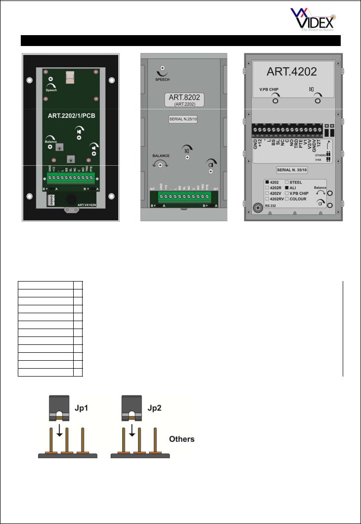
DIGITAL PANELS
Digital panels are available in the 8000 Series, 4000 Series and vandal resistant. The difference is mainly aesthetics; they all share the same connections, volume adjustments and programming menu. Digital panels can also be programmed with a PC using the SP37 programming kit. The PC connects to the panel via a jack socket located in the rear of the panel. Call progress is shown on a 2 line back lit LCD display. The panels also benefit from voice annunciation and call progress tones which guide the caller through the process of contacting an apartment.
CONNECTION
GND +12
-
L
BS
SL
NC
C
NO
TRD
PTE
JUMPERS
316x
B
FUNCTION
0V connection from PSU and ground connection
12-14Vdc from PSU
0V connection to bus
Bus connection (Data, speech and power) Busy connection for multiple door systems
Switched 0V output (Triggers during a call, for the duration of the call) Normally closed connection of the dry contact relay output
Common connection of the dry contact relay output Normally open connection of the dry contact relay output Trade code enable (Switched 0V to enable)
Push to exit button input (Switched 0V to trigger relay output)
The two jumpers on the panel must be set before powering up to initialise the panel in the correct mode. When using 3161 or 3162 telephones the jumper’s must be in the ‘B’ (316x) position, for all other telephones, videophones and video monitors the jumper’s should be in the ‘A’ (Others) position.
A B A
PAGE 5 of 68 |
VX2200 TECHNICAL MANUAL |
VER1.5 |
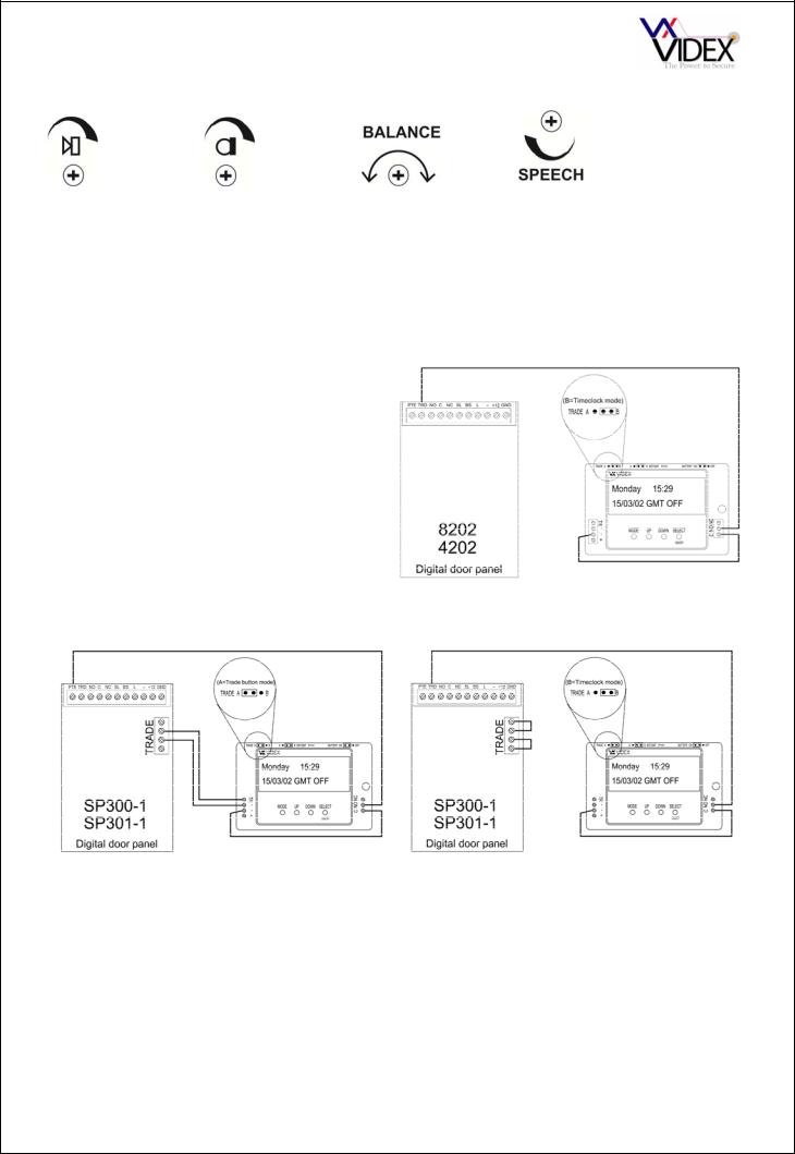
VOLUME ADJUSTMENT
There are four volume adjusters on the door panel as follows:-
Speaker volume |
Microphone volume |
Balance between mic |
Voice annunciation |
|
|
volume and speaker |
volume (May also be |
|
|
volume |
labelled ‘V.PB CHIP’ |
MAKING A CALL
All stages of the call will be acknowledged via the LCD display, voice annunciation and call progress tones. Additionally, the panel will also prompt the user with information on how to progress to the next stage of the call. To make a call simply enter the apartment number required and press ‘Enter’. Alternatively, if the panel has the scroll buttons (‘’,’’,’’) use the ‘’, ‘’ to locate the apartment to call then press ‘’.
USING THE TRADE
On the 4000 Series and 8000 Series panels the trade feature can only be used with a code. To use this facility first the TRD connection must to shorted to ground (As shown in the diagram to the right). To enter a trade code the panel must be in standby. Press the clear button (Display will show ‘TRADE C’), enter the code and then press ‘Enter’.
On the vandal resistant panel the trade button can be used as described above or alternatively the trade button can be used to simply release the door when the button is pressed (As long as the time clock is active). See diagram below for wiring these options.
WITHOUT CODE |
WITH CODE |
USING AN ACCESS CODE AND ENTERING PROGRAMMING MODE
On panels with a ‘CODE’ button, press ‘CODE’ followed by the code and press ‘Enter’. For panels without a ‘CODE’ button, press ‘0’ followed by the code and press ‘Enter’
Technical specifications |
|
|
Memory capacity |
: 998 users |
|
Working voltage |
: 13 Vdc +/- 10% |
|
Max. absorption |
: about 350 mA |
|
Working temperature |
: -10 +50 C° |
|
Relay contacts |
: 3A@30Vdc, 3A@120Vac |
|
PAGE 6 of 68 |
VX2200 TECHNICAL MANUAL |
VER1.5 |
|
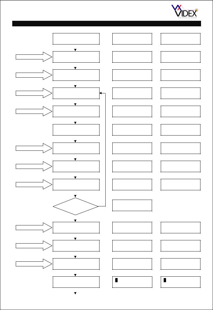
DIGITAL PANEL PROGRAMMING |
|
|||
|
|
|
LCD DISPLAY |
EXAMPLE |
|
|
ENTER PRESET FACTORY |
|
|
||
|
CODE 0+6x1 (0111111) |
CODE : ****** |
CODE : ****** |
||
PRESS ‘ENTER’ BUTTON |
|
|
|
||
(*) NOTE 2 |
ENTER MASTER CODE |
CODE : ****** |
CODE : ****** |
||
(1 to 6 digits) |
|
NEW : **** |
NEW : **** |
||
|
|
||||
PRESS ‘ENTER’ BUTTON |
|
|
|
||
(*) NOTE 2 |
ENTER TRADE CODE |
|
TRADE C : xxxxxx |
TRADE C : |
|
(1 to 6 digits) |
|
NEW : xxxx |
NEW : 1234 |
||
|
|
||||
PRESS ‘ENTER’ BUTTON |
|
|
|
||
(*) NOTE 4 |
ENTER MEMORY |
|
|
|
|
LOCATION (1 to 998) |
MEM.LOCATION: xxx |
MEM.LOCATION: 15 |
|||
|
|||||
PRESS ‘ENTER’ BUTTON |
|
|
|
||
(*) NOTE 1-2 |
ENTER FLAT NUMBER |
FLAT : |
FLAT : |
||
(1 to 6 Digits) |
|
NEW : xxxxxx |
NEW : 15 |
||
|
|
||||
PRESS ‘ENTER’ BUTTON |
|
|
|
||
|
ENTER PHONE ID |
|
ID PHONE : |
ID PHONE : |
|
|
ADDRESS (1 to 180) |
NEW : xxx |
NEW : 15 |
||
PRESS ‘ENTER’ BUTTON |
|
|
|
||
(*) NOTE 5 |
ENTER BLOCK NUMBER |
2206N N. : 0 |
2206N N. : |
||
(1 to 15) |
|
NEW : xx |
NEW : 1 |
||
|
|
||||
PRESS ‘ENTER’ BUTTON |
|
|
|
||
(*) NOTE 1-2 |
ENTER CODE TO OPEN |
DOOR CODE : |
DOOR CODE : |
||
DOOR (1 to 6 Digits) |
|
NEW : xxxxxx |
NEW : 1066 |
||
|
|
||||
PRESS ‘ENTER’ BUTTON |
|
|
|
||
(*) NOTE 6 |
ENTER USER NAME |
|
USER NAME : |
USER NAME : |
|
|
|
xxxxxxxxx |
HOGART STEVE |
||
|
|
|
|||
|
MORE |
YES |
|
|
|
|
|
MEM.LOCATION: |
|
||
|
FLATS? |
|
|
||
|
|
|
|
||
|
NO |
|
|
|
|
PRESS ‘ENTER’ TWICE |
|
|
|
||
(*) NOTE 2 |
INSERT SPEECH TIME |
SPEECH TIME : xxx |
SPEECH TIME : |
||
(1 to 255 Seconds) |
|
NEW : xxx |
NEW: 120 |
||
|
|
||||
PRESS ‘ENTER’ BUTTON |
|
|
|
||
(*) NOTE 2 |
INSERT DOOR TIME |
|
DOOR TIME : |
DOOR TIME : |
|
(1 to 255 Seconds) |
|
NEW : xxx |
NEW : 5 |
||
|
|
||||
PRESS ‘ENTER’ BUTTON |
|
|
|
||
(*) NOTE 2 |
ENTER DEVICE NO. |
|
DEVICE Nr. : xx |
DEVICE Nr. : |
|
(1 to 15) |
|
NEW : xx |
NEW : 1 |
||
|
|
||||
PRESS ‘ENTER’ BUTTON |
|
|
|
||
|
SET LANGUAGE. |
|
0=ENG 1=IT 2=ESP |
0=ENG 1=IT 2=ESP |
|
|
(0 to 5) |
|
3=POR 4=FR 5=GER |
3=POR 4=FR 5=GER |
|
|
CONTINUED ON NEXT PAGE |
|
|
||
PAGE 7 of 68 |
VX2200 TECHNICAL MANUAL |
VER1.5 |
|||
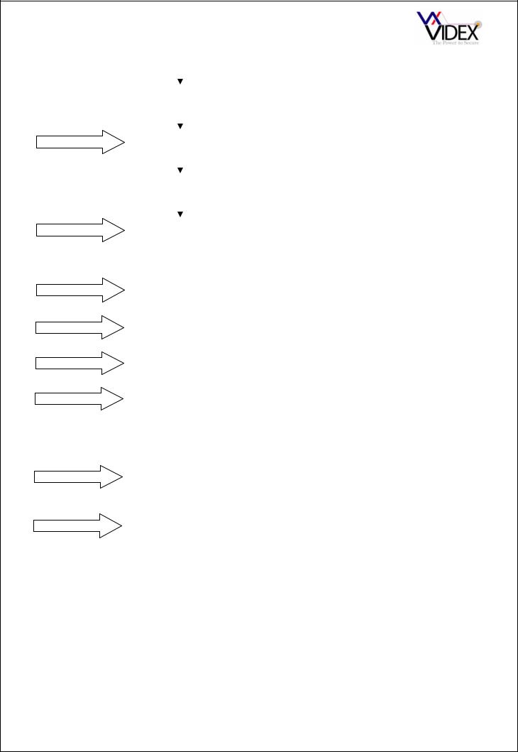
CONTINUED FROM PREVIOUS PAGE |
|
|
|
|
|
|
|
|
||
SELECT 0 - 5 |
|
|
|
|
|
|
|
|
|
|
|
|
|
|
|
|
|
|
|
|
|
|
SET SPEECH PLAYBACK |
|
|
|
=NO 1=ST 2=CMB |
|
|
|
=NO 1=ST 2=CMB |
|
|
|
|
0 |
0 |
||||||
SELECT 0 - 2 |
(0 to 2) |
|
|
|
SPEECH BOARD |
|
|
|
SPEECH BOARD |
|
|
|
|
|
|
|
|
|
|
|
|
|
|
|
|
|
|
|
|
|
|
|
|
|
|
|
|
|
|
|
|||
(*) NOTE 2-3 |
MASTER/SLAVE SETTING |
|
|
MASTER : NOT |
|
|
MASTER : YES |
|
||
(0 = SLAVE, 1=MASTER) |
|
|
1 = YES |
|
|
0 = NOT |
|
|||
|
|
|
|
|
|
|||||
SELECT 0 or 1 |
|
|
|
|
|
|
|
|
|
|
|
|
|
|
|
|
|
|
|
|
|
|
|
|
|
|
|
|
|
|||
|
AUTOMATIC FLAT TEST |
|
|
1 = TEST FLAT |
|
|
TEST FLAT 101 |
|
||
|
(1 or ENTER) |
|
|
“ENTER” = END |
|
|
ID PG 1-1 |
OK |
||
|
|
|
|
|
|
|
|
|
|
|
SELECT 1 or ENTER |
|
|
|
|
|
|
|
|
||
|
|
|
|
|
|
|
|
|
|
|
(*) NOTE 2-3 |
SYSTEM READY TO USE |
|
|
|
ENTER FLAT NR. |
|
|
|
ENTER FLAT |
|
|
|
|
|
- SEARCH - |
|
|
|
NUMBER |
|
|
|
|
|
|
|
|
|
|
|
||
|
|
|
|
|
|
|
|
|
|
|
NOTES:-
(*)NOTE 1
(*)NOTE 2
(*)NOTE 3
(*)NOTE 4
(*)NOTE 5
(*)NOTE 6
PRESS CLEAR BUTTON TO CANCEL THE LOCATION
DURING THE PROGRAMMING TO CONFIRM THE STORED DATA, PRESS ENTER TWICE
PROGRAM AS SLAVE ONLY IF THERE IS ANOTHER ENTRANCE PROGRAMMED AS MASTER ON THE SAME BUS
DOOR PANEL SOFTWARE VERSION 5.0 or later: LOCATIONS 0 & 999 ARE RESERVED FOR EDITING THE DISPLAY LOGOS.
EARLIER SOFTWARE: LOCATIONS 0 & 255 ARE RESERVED FOR EDITING THE DISPLAY LOGOS.
THIS SCREEN WILL ONLY APPEAR IF THE DOOR PANEL IS IN MAIN MODE. POWER UP WITH 0 HELD IN FOR MAIN MODE, POWER UP WITH ENTER HELD IN FOR LOCAL MODE
THIS SCREEN WILL ONLY APPEAR ON NAME SCROLL FACILITY DOOR PANELS. THE FOLLOWING KEYS ON THE KEYPAD DOUBLE UP AS LETTERS WHEN ENTERING NAMES:-
or A = Back |
CALL or B = Accept |
or C = Forward |
|||
1 |
= .& |
2 |
= ABC |
3 |
= DEF |
4 |
= GHI |
5 |
= JKL |
6 |
= MNO |
7 |
= PQRS |
8 |
= TUV |
9 |
= WXYZ |
|
|
0 |
= +-*/ |
|
|
PAGE 8 of 68 |
VX2200 TECHNICAL MANUAL |
VER1.5 |

DIGITAL PANEL MODE
The digital panel can be set to either MAIN MODE or LOCAL MODE. MAIN mode should only be used for panels that call all users and on systems that include 2206N devices (One per block or one for every 180 apartments), use LOCAL mode for all other applications. To set a digital panel as MAIN MODE, power up with the 0 button pressed. To set as LOCAL MODE, power up with ENTER pressed (The mode can also be changed via the PC programming software.
To use the digital front panel with 3000 series intercoms and videointercoms, press the “ENTER” button while powering up and wait until the display shows the message “S3000”, release the button.
To use the digital front panel with 900 series intercoms and videointercoms, press the “CLEAR” button while powering up and wait until the display shows the message “S900”, release the button.
Additional programming notes
a.During the programming of the master door panel, all slave door panels will be off line. (This inconvenience does not occur if the slave entrances are connected through Art.2206 on a separate bus);
b.If the programming of the MASTER device is wrong (Eg. Programmed as a SLAVE when it should be a MASTER), an error condition takes place signalled by the message “ERROR!” on the display. To recover from this situation keep the “0” button pressed until the display shows CODE. Perform the programming again correcting the error. Alternatively programming a SLAVE as a MASTER can cause feedback (Larsen effect) during the conversation (Only one master per level per block allowed).
c.The entering of values not admitted is signalled by an error message, the unit waits for a valid entry before continuing on with the programming.
d.Pressing the “CLEAR” button, at any stage will clear the current data previously entered.
e.To enter a number to call the concierge (if present) while the concierge is in night mode, combine the “flat number” (Concierge number) with the “ID PHONE” address n.1.
f.When using the door panel in MAIN MODE, the programming of each user will require the address of the 2206N (Block address) for which that user is connected.
PAGE 9 of 68 |
VX2200 TECHNICAL MANUAL |
VER1.5 |
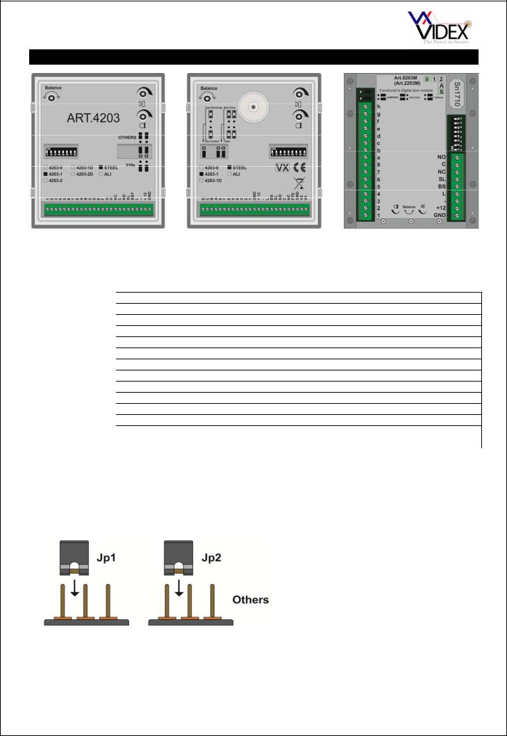
4000 SERIES/8000 SERIES FUNCTIONAL PANELS
4203 |
4283 |
8203 |
The 4000 and 8000 Series functional panels are of modular design each being capable of expansion up to 64 call buttons (only 32 buttons on the 4283 combined camera and speaker module). Programming options are carried out via dip-switches. Call progress tones are used to indicate the status of a call.
CONNECTION |
|
FUNCTION |
GND |
|
0V connection from PSU and ground connection |
+12 |
|
12-14Vdc from PSU |
- |
|
0V connection to bus |
L |
|
Bus connection (Data, speech and power) |
BS/BSY |
|
Busy connection for multiple door systems |
SL |
|
Switched 0V output (Triggers during a call, for the duration of the call) |
NC |
|
Normally closed connection of the dry contact relay output |
C |
|
Common connection of the dry contact relay output |
NO |
|
Normally open connection of the dry contact relay output |
PTE |
|
Push to exit button input (Switched 0V to trigger relay output) |
V1 |
|
+Sync of balanced video signal from camera (4283 only) |
V2/V |
|
- Sync of balanced video signal from camera (4283 only) When in coax mode used as |
|
|
video signal, screen of coax connects to GND |
MAKING A CALL
Press the relevant button: 5 quick beeps will indicate if the system is busy, otherwise the call will be signalled by a slow intermittent acoustic signal until the call is answered, the conversation time expires (programmable time) or the call is interrupted by pressing a push button for a minimum of 2 seconds. A short intermittent acoustic signal indicates that the door is open. If a wrong push button is pressed or if there is no answer, a new call will erase the previous one.
JUMPERS |
The two jumpers on the 4203 & 8203 panel |
|
|
|
must be set before powering up to initialise the |
|
panel in the correct mode. When using 3161 or |
|
3162 telephones the jumper’s must be in the |
316x |
‘316x’ position, for all other telephones, |
videophones and video monitors the jumper’s |
|
|
should be in the ‘Others’ position. |
There are also three jumpers on the 4283 module which set the lock output to either dry contact (C, NO & NC) or voltage output (Lock connects across GND and NO, NO being a 12Vdc output) and the other two are used to select the video output to be either balanced or composite.
PAGE 10 of 68 |
VX2200 TECHNICAL MANUAL |
VER1.5 |
VOLUME ADJUSTMENT
There are three volume adjusters on the door panel as follows:-
Speaker volume |
Microphone volume |
CONNECTING ADDITIONAL BUTTONS
Up to 64 buttons (32 on the 4283) can be connected to the modules using an X-Y matrix as shown here.
When using the 4000 Series button modules you will notice a number of jumpers on these modules which allow you to select if the buttons are common or isolated from each other.
Balance between microphone volume and speaker volume
DIP SWITCHES (4203 & 8203)
All DIP-SWITCH CHANGES MUST BE CONFIRMED BY POWERING DOWN THE MODULE AND THEN POWERING UP AGAIN.
Nr.1 |
Setting Up |
Switch 1 sets the panel as a Master or Slave. One master required on each bus. |
|||
OFF |
= Slave |
|
|
||
ON |
= Master (default) |
|
|
||
|
|
|
|
Switches 2 & 3 define the range of |
|
Nr.2 |
Nr.3 |
Settings |
|
||
|
Phone IDs generated by the unit |
||||
OFF |
OFF |
from buttons 1 to 64 |
|||
when the call buttons are pressed. |
|||||
ON |
OFF |
from buttons 65 to 128 |
|||
For example with dip-switch 2 and |
|||||
OFF |
ON |
from buttons 129 to 180 |
|||
3 both OFF, the push button |
|||||
ON |
ON |
from buttons 1 to 64 with 900 series devices |
|||
connected between terminals “1” |
|||||
|
|
|
|
||
and “a” calls ID PHONE 1 while the same push button, with dip-switch 2 ON and dip-switch 3 OFF, will call
PHONE ID 65.
Nr.4 |
Setting Up |
|
Switch 4 sets the maximum conversation time. |
OFF |
= 1 min |
|
|
ON |
= 2 min |
|
|
|
|
|
|
Nr.5 |
Setting Up |
|
Switch 5 sets the relay operation time. |
OFF |
= 2 seconds |
|
|
|
|
||
ON |
= 6 seconds |
|
|
Nr.6 |
Nr.7 |
Nr.8 |
Setting Up |
OFF |
OFF |
OFF |
= 1 |
ON |
OFF |
OFF |
= 2 |
OFF |
ON |
OFF |
= 3 |
ON |
ON |
OFF |
= 4 |
OFF |
OFF |
ON |
= 5 |
ON |
OFF |
ON |
= 6 |
OFF |
ON |
ON |
= 7 |
ON |
ON |
ON |
= 8 |
Switches 6, 7 & 8 set the panels ID. This is required on video systems and systems that include a concierge as it allows an apartment or the concierge to recall the panel to activate the camera, switch on the audio and also identifies to the concierge which panel a call originates.
PAGE 11 of 68 |
VX2200 TECHNICAL MANUAL |
VER1.5 |
DIP SWITCHES (4283)
All DIP-SWITCH CHANGES MUST BE CONFIRMED BY POWERING DOWN THE MODULE AND THEN POWERING UP AGAIN.
Nr.1 |
Setting Up |
|
|
Switch 1 sets the panel as a Master or Slave. One master required on each bus. |
|||
OFF |
= Slave |
|
|
|
|
||
ON |
= Master (default) |
|
|
||||
|
|
|
|
|
|
|
Switches 2, 3 & 4 define the range of Phone IDs generated |
Nr.2 |
Nr.3 |
Nr.4 |
|
Settings |
|||
|
by the unit when the call buttons are pressed. For example |
||||||
OFF |
OFF |
OFF |
|
from buttons 1 to 32 |
|||
|
with dip-switch 2, 3 and 4 OFF, the push button connected |
||||||
ON |
OFF |
OFF |
|
from buttons 33 to 64 |
|||
|
between terminals “1” and “a” calls ID PHONE 1 while the |
||||||
OFF |
ON |
OFF |
|
from buttons 65 to 96 |
|||
|
same push button, with dip-switch 2 ON and dip-switch 3 |
||||||
ON |
ON |
OFF |
|
from buttons 97 to 128 |
|||
|
& 4 OFF, will call PHONE ID 33. |
||||||
OFF |
OFF |
ON |
|
from buttons 129 to 160 |
|||
|
|
||||||
ON |
OFF |
ON |
|
from buttons 161 to 180 |
|
||
OFF |
ON |
ON |
|
from buttons 1 to 32 |
|
||
|
|
|
|
|
(900 Series phones) |
|
|
ON |
ON |
ON |
|
from buttons 33 to 64 |
|
||
|
|
|
|
|
(900 Series phones) |
|
|
|
|
|
Switch 5 sets the maximum conversation time. |
||||
Nr.5 |
Setting Up |
||||||
OFF |
= 1 min |
|
|
|
|
|
|
ON |
= 2 min |
|
|
|
|
|
|
|
|
|
|
||||
Nr.6 |
Setting Up |
|
Switch 6 sets the relay operation time. |
||||
OFF |
= 2 seconds |
|
|||||
|
|
|
|
||||
ON |
= 6 seconds |
|
|
|
|
||
Nr.7 |
Nr.8 |
Nr.9 |
Setting Up |
OFF |
OFF |
OFF |
= 1 |
ON |
OFF |
OFF |
= 2 |
OFF |
ON |
OFF |
= 3 |
ON |
ON |
OFF |
= 4 |
OFF |
OFF |
ON |
= 5 |
ON |
OFF |
ON |
= 6 |
OFF |
ON |
ON |
= 7 |
ON |
ON |
ON |
= 8 |
Switches 7, 8 & 9 set the panels ID. This is required on video systems and systems which include a concierge as it allows an apartment or the concierge to recall the panel to activate the camera and also identifies to the concierge which panel a call is coming from.
Switch 10 not used.
Programming notes
In case of a wrong Master/Slave configuration (Dip-switch no.1), the following problems can occur:
a.if the unit should be a Master but is configured as a Slave, the error is signalled by an acoustic intermittent signal until the problem is resolved;
b.if the unit should be Slave but is configured as Master, the impedance of the system will have a lack of balance, causing feedback (“Larsen” effect).
When a system includes a concierge unit, the push button combined with the Phone ID 1 will call to the concierge regardless of if the concierge is in day or night mode.
MODULE BUTTON WIRING COLOUR CODE:-
Colour |
Button |
blue |
Buttons Common |
yellow |
Button 1 |
red |
Button 2 |
white |
Button 3 (4000 Series only) |
black |
Button 4 (4000 Series only) |
Technical specifications |
|
Working voltage |
: 13 Vdc +/- 10% |
Max. absorption |
: approx 350 mA |
Working temperature |
: -10 +50 C° |
Relay contacts |
: 3A@30Vdc, 3A@120Vac |
CALL PROGRESS LED’S
Symbol LED meaning
The first LED (red), indicates that it is not possible to make a call because a call or a conversation is in progress (from the outdoor station from which you are calling or from another outdoor station on systems with multiple entrances).
The second LED (red), indicates that a call is in progress. The LED will switch OFF when the call is answered.
The third LED (yellow), indicates the call has been answered. The LED will switch OFF at the end of the conversation.
The fourth LED (green), indicates that the door lock has been released. It will switch OFF at the end of the “door opening” time.
PAGE 12 of 68 |
VX2200 TECHNICAL MANUAL |
VER1.5 |
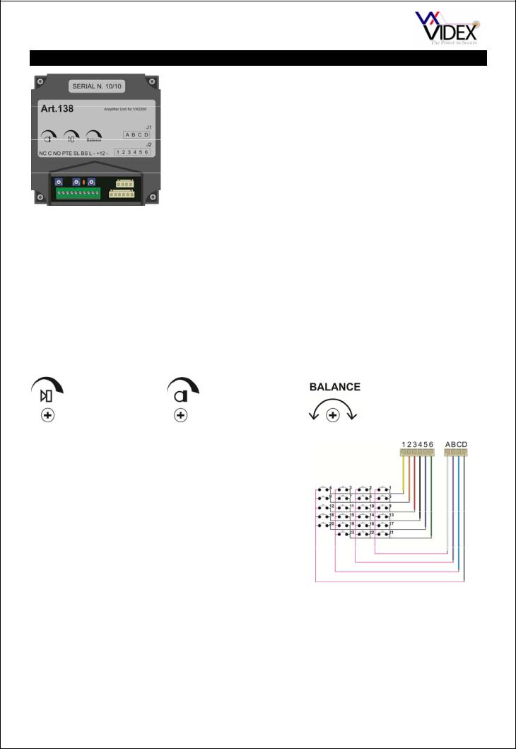
VANDAL RESISTANT FUNCTIONAL PANELS
|
This module is used in the VX2200 2 wire audio, 6 wire video functional |
|
vandal resistant door panels and includes all features required for audio & |
|
video installations. A 13.8Vdc PSU is required to power this system. Up to |
|
23 buttons can be connected to this module. (This module cannot be used |
|
with 316x phones). |
|
MAKING A CALL |
|
Press the relevant button: 5 quick beeps will indicate if the system is busy, |
|
otherwise the call will be signalled by a slow intermittent acoustic signal |
|
until the call is answered, times out or the call is interrupted by pressing a |
|
push button for more than 2 seconds. A short intermittent acoustic signal |
|
indicates that the door is open. A yellow LED indicates conversation has |
|
begun and a green LED indicates relay activation. |
|
|
CONNECTION |
FUNCTION |
NC |
Normally closed connection of relay |
C |
Common connection of relay |
NO |
Normally open connection of relay |
PTE |
Push to exit button input (Switch to 0V) |
SL |
Switched 0V output (0V during a call for video power supply switching) |
BS |
Busy signal to other panels (12Vdc in standby, 0V during a call) |
L |
Bus connection approx. 7.5Vdc |
- |
0V for bus |
+12 |
12Vdc input to power the amplifier |
- |
0V from PSU |
VOLUME ADJUSTMENT
There are three volume adjusters on the door panel as follows:-
Speaker volume |
Microphone volume |
CONNECTING ADDITIONAL BUTTONS
Up to 23 buttons can be connected to the modules using an X-Y matrix and the wiring harness as shown here.
Balance between microphone volume and speaker volume
Factory reset
To revert to factory default settings as shown in ( ) below, power down the 138 amplifier short PTE to ground, power up and await 6 beeps, remove the short.
Programming
There are several features of the amplifier that can be programmed into non-volatile memory. Entering each programming stage requires the shorting of certain connections on the button matrix using the connectors 5 & 6 labelled above. Remove the plug from connector ABCD so that the connectors 5 or 6 can be connected to the relevant pin as outlined in the tables below. Beeps are used to indicate the new setting as outlined in the tables below. The procedure to program these settings is as follows:-
PAGE 13 of 68 |
VX2200 TECHNICAL MANUAL |
VER1.5 |

1.Power down the 138 amplifier
2.Connect the plug (5 or 6) to A,B,C or D depending on the setting to program as outlined below.
3.Power up the 138 amplifier
4.Listen to the beeps from the 138 amplifier, When the correct number is reached as outlined below, remove the link between the plug and A,B,C or D.
5.A long confirmation beep will confirm the new setting has been stored.
DEFAULTS ARE SHOWN IN ( )
MASTER or SLAVE
Set amplifier as master or slave (Each system requires one master, any additional door’s on a system must be set to slave).
Power up with wires 5 & A shorted. Wait for correct beeps then remove short.
1 BEEP |
2 BEEPS |
(Master) |
Slave |
BANK of BUTTONS
Set the bank of buttons relevant to the button matrix (For most systems this will be buttons 1-23 but for larger systems it may be necessary to have the buttons start at 25 through to 47, i.e. Button 1A would call address 25 as oppose to 1).
Power up with wires 5 & B shorted. Wait for correct beeps then remove short.
1 BEEP |
2 BEEPS |
(Button addresses 1 – 23) |
Button addresses 25-47 |
MAXIMUM CALLING TIME BEFORE ANSWER
Set the maximum length of a call ‘wait to answer’ before the call is cleared down. This does not affect the conversation time which can be programmed separately.
Power up with wires 5 & C shorted. Wait for correct beeps then remove short.
1 BEEP |
2 BEEPS |
3 BEEPS |
4 BEEPS |
5 BEEPS |
10 Seconds |
20 Seconds |
30 Seconds |
(40Seconds) |
50Seconds |
|
|
|
|
|
6 BEEP |
7 BEEPS |
8 BEEPS |
9 BEEPS |
10 BEEPS |
60 Seconds |
70 Seconds |
80 Seconds |
90Seconds |
100Seconds |
CONVERSATION TIME
Set the maximum length of a conversation before the call is automatically cleared down.
Power up with wires 5 & D shorted. Wait for correct beeps then remove short.
1 BEEP |
2 BEEPS |
3 BEEPS |
4 BEEPS |
5 BEEPS |
20 Seconds |
40 Seconds |
(60 Seconds) |
80 Seconds |
100 Seconds |
|
|
|
|
|
6 BEEP |
7 BEEPS |
8 BEEPS |
9 BEEPS |
10 BEEPS |
120 Seconds |
140 Seconds |
160 Seconds |
180 Seconds |
200 Seconds |
RELAY TIME
Door open relay time
Power up with wires 6 & A shorted. Wait for correct beeps then remove short.
1 BEEP |
2 BEEPS |
3 BEEPS |
4 BEEPS |
5 BEEPS |
2.5 Seconds |
(5 Seconds) |
7.5 Seconds |
10 Seconds |
12.5 Seconds |
|
|
|
|
|
6 BEEP |
7 BEEPS |
8 BEEPS |
9 BEEPS |
10 BEEPS |
15 Seconds |
17.5 Seconds |
20 Seconds |
22.5 Seconds |
25 Seconds |
DEVICE NUMBER
It is very important on video systems and systems with a concierge that each door panel amplifier has a unique device number.
Power up with wires 6 & B shorted. Wait for correct beeps then remove short.
1 BEEP |
2 BEEPS |
3 BEEPS |
4 BEEPS |
5 BEEPS |
(Device 1) |
Device 2 |
Device 3 |
Device 4 |
Device 5 |
|
|
|
|
|
6 BEEP |
7 BEEPS |
8 BEEPS |
9 BEEPS |
10 BEEPS |
Device 6 |
Device 7 |
Device 8 |
Device 9 |
Device 10 |
PAGE 14 of 68 VX2200 TECHNICAL MANUAL VER1.5
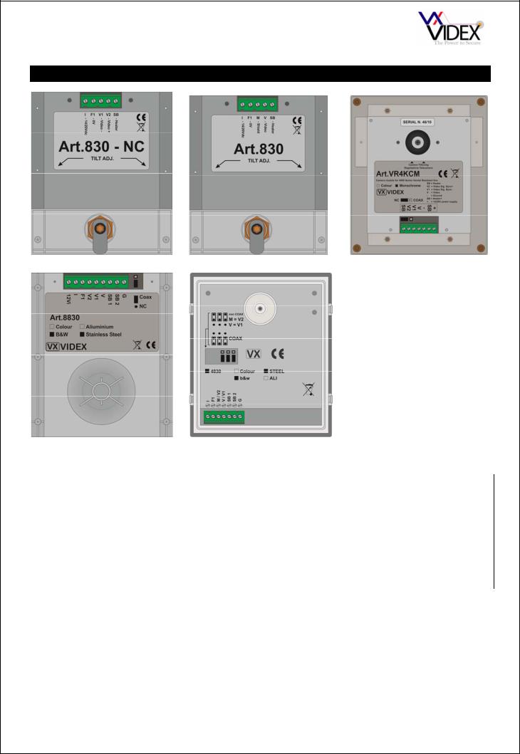
CAMERA MODULES
All camera modules are available in mono or colour. The mono cameras include infra-red illumination to illuminate a subject in poor lighting conditions (max range 80cm). The colour cameras include white LED’s which switch on during a call. With the exception of the 830 and 830NC, the cameras are all able to support both balanced and composite video outputs which is selectable, adjusting the position of the jumpers. The 4000, 8000 and VR
cameras all include a ball joint camera swivel allowing the camera direction to be adjusted 10° in any direction.
CONNECTION |
|
FUNCTION |
I, + |
|
Switched +20Vdc Input to power camera |
F1, - |
|
0V power to camera |
V |
|
Composite video output (Coax centre core) |
M |
|
Screen of coax |
V1 |
|
+Sync balanced video connection |
V2 |
|
- Sync balanced video connection |
SB, SB1, SB2 |
|
Heater connections |
G |
|
Ground |
12VI |
|
Alternate 12Vdc supply (Used instead of 20Vdc into I |
JUMPERS
On camera’s which include jumpers these should be set according to the type of video signal used. If the video signal and cable type is composite with coax cable then ensure all jumpers are towards the ‘COAX’ position. Alternatively if the video is a balanced signal using twisted pair cable then ensure the jumpers are all set to NC (Non Coax).
PAGE 15 of 68 |
VX2200 TECHNICAL MANUAL |
VER1.5 |
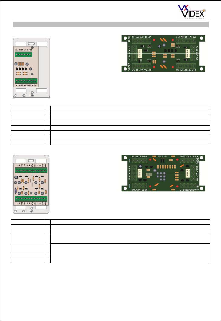
VIDEO DISTRIBUTION
COAX VIDEO
CONNECTION
Vin, V M Vout, V
V1, V2, V3, V4 +12 +20
0V
The version to the left is the Art.894 and the version to the right is the 894I. Both versions are 4 way video splitters therefore one is required for every four videophones.
The 894I also benefits from over
current protection for each of the four 20V (500mA max) outputs meaning, if a short appears on those connections or a fault towards the monitor occurs then the 20V to that output will be disconnected to allow all other outputs to continue working. The red LED next to the output will illuminate to show the problem output.
FUNCTION
Video in from previous video distributor, control cabinet or camera Coax cable screen
Video out to next video distributor or end of line termination. Video output to four videophones (4 outputs)
12V input to power the video distributor (Powered from videophones) 20Vdc feed through from video power supply to monitors (894I only) 0V feed through from video power supply to monitors (894I only)
NON-COAX (BALANCED VIDEO)
CONNECTION
V1
V2
V1a, V1b, V1c, V1d
V2a, V2b, V2c, V2d
+20, + 0V, -
The version to the left is the Art.316 and the version to the right is the 316I. Both versions are 4 way video splitters therefore one is required for every four videophones.
The 316I also benefits from over
current protection for each of the four 20V (500mA max) outputs meaning, if a short appears on those connections or a fault towards the monitor occurs then the 20V to that output will be disconnected to allow all other outputs to continue working. The red LED next to the output will illuminate to show the problem output.
FUNCTION
+Sync balanced video in from previous video distributor, control cabinet or camera
-Sync balanced video in from previous video distributor, control cabinet or camera
+Sync video output to videophone (4 Outputs)
-Sync video output to videophone (4 Outputs)
20Vdc feed through to monitors and power from video power supply 0V feed through from video power supply to monitors
END OF LINE
On coax video systems it is necessary to terminate any unused outputs with a 75Ω resistor. This is achieved on the 894 by fitting a 75Ω resistor across Vn and M of the unused outputs. On the 894I there are jumpers next to each output which should be closed if the output is not used and open if it is. Additionally it is also necessary to fit an end of line resistor across Vout & M of the last video distributor (Both coax and non-coax versions) to terminate the end of the line. Again on the 894I/316I there is a jumper(s) which should be closed on the last unit instead of fitting a resistor (Labelled EOL on the 894I and End of line on the 316I).
PAGE 16 of 68 |
VX2200 TECHNICAL MANUAL |
VER1.5 |
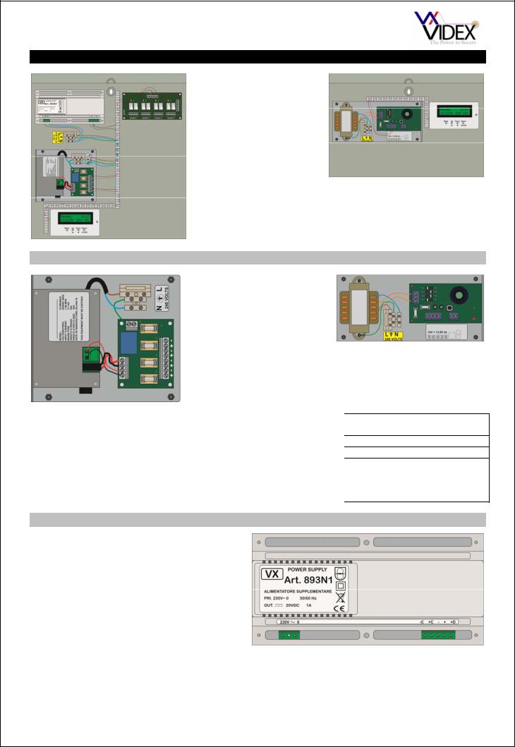
CONTROL EQUIPEMENT
As there are many variations of control cabinet available (Audio, video, with isolation, multiple door etc). The components that make up a control cabinet are listed below:-
13.8Vdc SYSTEM PSU
Battery backup is a standard feature of these PSU’s. We recommend a 7Ah sealed lead acid battery. 1A, 2A, 3A & 4A PSU’s are normally used on this system, all of which have a regulated output voltage of
13.8Vdc. DC out and battery trickle charge are independently fused. Additionally the 4A PSU includes a fan out PCB which shares the available 4A’s between 4 independently fused outputs. The combination of these fuse values can be anything as long as the 4 outputs are fused to no more than 4A. Fuse values are as follows:-
PSU |
MAINS FUSE |
DC OUT FUSE |
BATTERY TRICKLE CHARGE |
|
|
|
FUSE |
2 Amp |
T315mA |
F2.0A |
T315mA |
3 Amp |
T630mA |
F3.0A |
T315mA |
4 Amp |
T3.15A |
Main fuse F4.0A. Fan out |
T1A |
|
|
fuses can be any |
|
|
|
combination up to a total of |
|
|
|
4A |
|
20Vdc VIDEO PSU
The Art.893N1 is a 1A pulse, 800mA continuous 20Vdc PSU. It is a switched output supply requiring either a positive trigger on terminal ‘+C’ or a negative trigger on ‘-C’ to switch the 20Vdc output on. There are no fuses in this PSU. If there is a short on the output or an over current situation then the PSU will shut down until the problem is resolved.
CONNECTION |
FUNCTION |
|
|
-C |
0V trigger to activate output |
|
|
+C |
+8-30Vdc to activate output |
|
|
- |
0V output connection |
|
|
+ |
20Vdc output connection |
|
|
+D |
20Vdc output via diode |
|
|
PAGE 17 of 68 |
VX2200 TECHNICAL MANUAL |
VER1.5 |
|
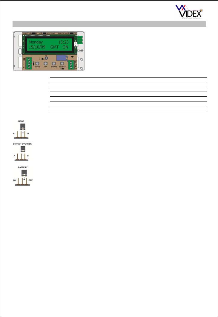
TIME CLOCK
The 701T is a BST/GMT time clock with 6 programmable on/off periods and two modes of operation. The first mode being a standard time clock mode whereby the dry contact relay output triggers for the length of an on/off period. The second mode is known as the trade button mode and only operates the relay when the trade input is triggered and during an active on/off period. The relay would then stay energised for a programmed time (01-99 seconds).
CONNECTION |
|
FUNCTION |
+ |
|
12Vdc power supply input |
- |
|
0V power supply connection |
TR |
|
Trade button input (Shorts to 0V) |
C |
|
Common connection of dry contact relay output |
NO |
|
Normally open connection of dry contact relay output |
NC |
|
Normally closed connection of dry contact relay output |
JUMPERS
The jumper in the top right selects the time clocks mode of operation. A = TRADE BUTTON MODE
B = TIME CLOCK MODE
The jumper in the middle Enables/Disables automatic BST/GMT time correction
A = AUTOMATIC ADJUSTMENT DISABLED
B = AUTOMATIC ADJUSTMENT ENABLED
The time clock includes a battery to maintain the time while the time clock isn’t powered. The battery should maintain the time and settings for a minimum of 3 months.
ON = BATTERY ENABLED
OFF = BATTERY DISABLED (Should be moved to ON when installed)
TECHNICAL SPECIFICATION |
|
|
|
Supply Voltage |
: |
12V DC or 12V AC |
|
Standby Current (Relay off) |
: |
47mA |
|
Standby Current (Relay on) |
: |
67mA |
|
Battery backup |
: |
Min. 3 Months |
|
Relay contacts (Dry contact) |
: |
3A @ 24V DC |
|
|
|
3A @ 120V AC |
|
On/Off times available |
: |
Six |
|
|
: |
ON/OFF period 1 will switch off at the off time for that period |
|
|
|
regardless of manual override. |
|
|
: |
ON/OFF period 2-6 will Not switch off at the off time for that period if |
|
|
|
manual override is pressed. |
|
Trade mode relay time |
: |
From 1 second to 99 seconds |
|
Dimensions |
: |
110mm x 70mm x 30mm |
|
PAGE 18 of 68 |
|
VX2200 TECHNICAL MANUAL |
VER1.5 |
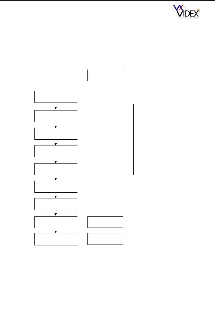
TIME CLOCK PROGRAMMING
Programming is carried out by means of the four push buttons. The mode button advances through the modes beginning with mode 1 which allows the editing of the time and date, mode 2 – 7 allows the editing of the time bands and mode 8 allows the editing of the relay time in trade mode (Note: mode 8 only appears in trade mode). The up/down buttons allow the underlined information to be edited (pressing these buttons once will change the value by one, holding the button down will auto increment the value until the button is released) and the select button allows the underline cursor to rotate round to the next item on the display. If the time clock is inadvertently left in programming mode it will automatically revert to standby mode after a preset time.
DISPLAY
Press the mode button to edit the time and date
Press the mode button to edit the 1st on/off time
Press the mode button to edit the 2nd on/off time
Press the mode button to edit the 3rd on/off time
Press the mode button to edit the 4th on/off time
Press the mode button to edit the 5th on/off time
Press the mode button to edit the 6th on/off time
Press the mode button to edit the relay time
Press the mode button to return to standby mode
Monday 15:20
15/01/02 GMT OFF
TIME - |
15:20 |
DATE - |
15/01/02 |
|
|
|
|
ON 1 |
10:15 AD |
OFF 1 - |
10:30 |
|
|
|
|
ON 2 - |
11:00 Mo |
OFF 2 - |
12:30 |
|
|
|
|
ON 3 - |
15:45 WD |
OFF 3 - |
17:20 |
|
|
|
|
ON 4 - |
18:15 We |
OFF 4 - |
20:15 |
|
|
|
|
ON 5 - |
19:30 WE |
OFF 5 - |
20:45 |
|
|
|
|
ON 6 - |
10:00 AD |
OFF 6 - |
19:00 |
|
|
RELAY TIME - 05
Monday 15:20
15/01/02 GMT OFF
The days of the week are abbreviated as shown below
|
Monday |
Mo |
|
|
|
|
|
|
Tuesday |
Tu |
|
|
|
|
|
|
Wednesday |
We |
|
|
|
|
|
|
Thursday |
Th |
|
|
|
|
|
|
Friday |
Fr |
|
|
|
|
|
|
Saturday |
Sa |
|
|
|
|
|
|
Sunday |
Su |
|
|
|
|
|
|
Week Days |
WD |
|
|
|
|
|
|
Week Ends |
WE |
|
|
|
|
|
|
All Days |
AD |
|
|
|
|
|
NOTE: To reset the time clock completely, simply power up with the UP button pressed
PAGE 19 of 68 |
VX2200 TECHNICAL MANUAL |
VER1.5 |
VX123 VIDEO SWITCHING PCB
CONNECTION
GND +12 +20 V1 V2 SL
The VX123 is used on multiple door video systems to switch the video from a single door to the bus. Each PCB can control up to four video panels. Multiple PCB’s can be used to expand the system. A green LED indicates when a panel is connected to the bus.
FUNCTION
0V
12Vdc from PSU to power the PCB
20Vdc switched to the relevant door when triggered
+ Sync video signal switched to relevant door when triggered - Sync video signal switched to relevant door when triggered Trigger input to activate a channel (Switched 0V)
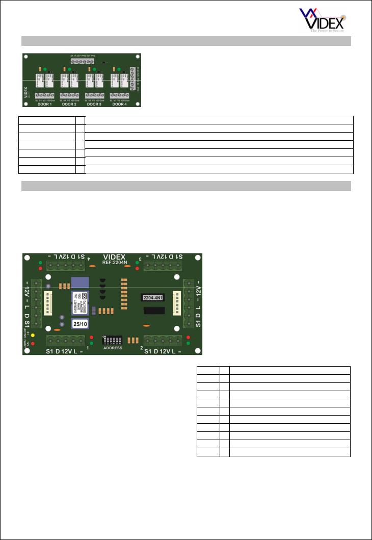
4 WAY ISOLATION PCB (2204N)
The 2204N will protect against shorts or faults on all connections to an apartment. Plug in connections are used for easy maintenance. The 2204N can also be connected as a bus in a prewired cabinet and is addressed using a 6 way dip-switch bank. For video systems there is an additional video isolation card (316I for non-coax or 894I for coax) which piggy backs this board and includes all the additional connections for video. There are 10 LED’s on each card which can be used to identify when a channel is in use (Green channel LED on) and to indicate a variety of faults such as shorts on +12V out, short on bus and S1 permanently active.
Connection |
|
Function |
- |
|
0V |
L |
|
Bus connection |
12V |
|
+12Vdc |
D |
|
Door open LED (Switched 12V) |
S1 |
|
Spare service button on telephone |
|
|
(Switched 0V) |
Six way connectors – Main bus in/out
Five way connectors – Four outputs to apartments.
LED |
Function |
D1 |
Bus fault output 1 |
D8 |
Bus fault output 2 |
D14 |
Bus fault output 3 |
D19 |
Bus fault output 4 |
D7 |
Output 1 active |
D6 |
Output 2 active |
D5 |
Output 3 active |
D4 |
Output 4 active |
D21 |
S1 service switch active |
D3 |
12V out fault on one of the outputs |
PAGE 20 of 68 |
VX2200 TECHNICAL MANUAL |
VER1.5 |

OPERATION
In stand-by the phones connected to the 2204N are physically disconnected from the main BUS. During a call the selected channel will be connected to the main bus, the green LED next to the channel will illuminate for the length of the call.
PROGRAMMING (DIP-SWITCHES)
The dip-switches are used to address the PCB. The address of the PCB must correspond with the address of the telephone in the apartment. For example, output 1 of the first 2204N must be connected to a telephone with address 1, output 3 must be connected to a telephone with address 3, Output 1 of the second 2204N must be connected to a telephone with address 5 etc. The table below shows all available addresses.
|
Addresses of: |
|
|
|
|
Addresses of: |
|
|
|
|
Addresses of: |
|
|
|
|||
|
DIP-SW |
Connected Intercoms |
|
|
Connected Intercoms |
|
DIP-SW |
Connected Intercoms |
|||||||||
2204 no. |
Settings |
|
|
|
|
2204 No. |
DIP-SW |
|
|
|
|
2204 No. |
Settings |
|
|
|
|
|
L1 |
L2 |
L3 |
L4 |
Settings |
L1 |
L2 |
L3 |
L4 |
|
L1 |
L2 |
L3 |
L4 |
|||
|
|
|
|
|
|||||||||||||
0 |
|
1 |
2 |
3 |
4 |
16 |
|
65 |
66 |
67 |
68 |
32 |
|
129 |
130 |
131 |
132 |
1 |
|
5 |
6 |
7 |
8 |
17 |
|
69 |
70 |
71 |
72 |
33 |
|
133 |
134 |
135 |
136 |
2 |
|
9 |
10 |
11 |
12 |
18 |
|
73 |
74 |
75 |
76 |
34 |
|
137 |
138 |
139 |
140 |
3 |
|
13 |
14 |
15 |
16 |
19 |
|
77 |
78 |
79 |
80 |
35 |
|
141 |
142 |
143 |
144 |
4 |
|
17 |
18 |
19 |
20 |
20 |
|
81 |
82 |
83 |
84 |
36 |
|
145 |
146 |
147 |
148 |
5 |
|
21 |
22 |
23 |
24 |
21 |
|
85 |
86 |
87 |
88 |
37 |
|
149 |
150 |
151 |
152 |
6 |
|
25 |
26 |
27 |
28 |
22 |
|
89 |
90 |
91 |
92 |
38 |
|
153 |
154 |
155 |
156 |
7 |
|
29 |
30 |
31 |
32 |
23 |
|
93 |
94 |
95 |
96 |
39 |
|
157 |
158 |
159 |
160 |
8 |
|
33 |
34 |
35 |
36 |
24 |
|
97 |
98 |
99 |
100 |
40 |
|
161 |
162 |
163 |
164 |
9 |
|
37 |
38 |
39 |
40 |
25 |
|
101 |
102 |
103 |
104 |
41 |
|
165 |
166 |
167 |
168 |
10 |
|
41 |
42 |
43 |
44 |
26 |
|
105 |
106 |
107 |
108 |
42 |
|
169 |
170 |
171 |
172 |
11 |
|
45 |
46 |
47 |
48 |
27 |
|
109 |
110 |
111 |
112 |
43 |
|
173 |
174 |
175 |
176 |
12 |
|
49 |
50 |
51 |
52 |
28 |
|
113 |
114 |
115 |
116 |
44 |
|
177 |
178 |
179 |
180 |
13 |
|
53 |
54 |
55 |
56 |
29 |
|
117 |
118 |
119 |
120 |
|
|
|
|
|
|
14 |
|
57 |
58 |
59 |
60 |
30 |
|
121 |
122 |
123 |
124 |
|
|
|
|
|
|
15 |
|
61 |
62 |
63 |
64 |
31 |
|
125 |
126 |
127 |
128 |
|
|
|
|
|
|
Technical specifications |
|
|
Number of outputs |
: 4 |
|
Addressing range |
: from 0 to 44 |
|
Working temperature |
: -10 +50 C° |
|
12V output current max. |
: 200mA |
|
PAGE 21 of 68 |
VX2200 TECHNICAL MANUAL |
VER1.5 |
 Loading...