


Kristallo Series
Art. KRV7727”Handsfree videomonitor for systems using composite video signal |
R02A |
(coax) or balanced (twisted pair) |
|
|
|
|
|
|
|
G |
H |
I |
|
A |
B |
C |
|
D |
|
|
|
|
|
|
|
190 |
|
32 |
38 |
9 |
|
|
|
|
|
|
|
|
|
SW1 |
SW2 |
|
Art |
|
|
|
|
|
|
|
DOL |
|
|
|
|
|
|
|
|
|
SB |
|
|
|
|
|
|
|
|
|
AL |
|
. |
|
|
|
|
|
|
|
|
KRV772 |
|
|
|
|
|
|
|
|
LB |
|
|
|
|
|
|
|
|
|
L |
|
|
|
|
|
|
|
|
|
12Vin |
||
|
|
|
|
|
|
|
12Vout |
inMade |
|
|
|
|
|
147 |
146 |
|
GND |
|
|
|
|
|
|
|
V2 |
|
|||
|
|
|
|
|
|
|
V1 |
|
Italy |
|
|
|
|
|
|
|
+20 |
|
|
|
|
|
|
|
|
|
+VD |
|
|
|
|
E |
F |
E |
|
|
|
|
|
Fig. 1 Front |
|
|
|
|
|
Fig. 2 Back |
|
|
|
|
|
|
|
|
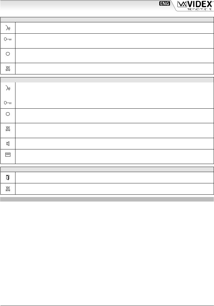
DESCRIPTION |
|
|
|
|
Intelligent Hands free video monitor for the VX2200 digital sys |
Microphone |
|
8 Way dip switch bank |
|
tem using a 7” 800x480 pixel resolution full colour active matrix |
Display |
|
4 Way dip switch bank |
|
LCD monitor with capacitive touch sensitive buttons for “door |
“Door Open” LED |
I |
Connection terminals |
|
open/concierge call” , “answer/camera recall”, “service button“, |
“Privacy ON” LED |
|
|
|
“privacy” plus 4 buttons for adjustment and programming and |
Touch buttons |
|
|
|
2 LED’s related to the videophone operation. 2 LED’s indicating |
F Loudspeaker |
|
|
|
the door open/close status (requires an additional wire) and the activation/deactivation of the privacy |
are also inclusive. The vid- |
|||
eomonitor includes an intercommunication facility (available only between the Kristallo range of videophones and intercoms) that enables intercommunication between devices in the same apartment (same PHONE ID but different extension address) or between devices installed in different apartments (different PHONE ID). Programming and settings are available through the touch buttons. Adjustable speech and melody volume, picture brightness and hue, programmable number of rings, aux service duration, privacy service duration, melody and the extension ID for intercommunication.
OPERATION
DURING STAND-BY
Camera recall
Press a number of times equal to the ID value of the door panel to switch ON.
When the connection is made, press again to end the call.
Call the concierge
Press to book a call to the digital concierge if installed on the system.
Service button
Press to activate the service (if connected) for the programmed time (SB terminal open collector output). The unit emits 3 “beep“ and the  LED will flash, then returns to stand-by mode.
Privacy service
Press to enable the privacy service. The LED  turns on. The service is deactivated by pressing again the same button or when the programmed time expires.
|
|
Intercommunication among devices in different apartments |
Intercommunicationbetweendevicesinthesameapartment |
|
|
Press a number of times equal to the PHONE ID of the de- |
Press a number of times equal to the EXTENSION ID of the |
|
|
||
|
|
vice to call (from 1 to 9). |
device to call (from 1 to 9). |
Melody volume
Press to increase or decrease the melody volume.
Art. KRV772 - Installation instructions |
- 1 - |
66250965 - V4.0 - 31/05/19 |
Kristallo Series
Art. KRV772 7” Handsfree videomonitor for systems using composite video signal (coax) or balanced (twisted pair)
DURING A CALL
Answer a call
Press to answer the call and start the conversation.
Open the door
Press to activate the door open relay of the outdoor unit and end the connection. The  “LED will flash then the unit returns to stand-by mode.
Service button
Press to activate the service (if connected) for the programmed time (SB terminal open collector output). The unit emits 3 “beeps“ and the  LED will flash, then return to stand-by mode.
Reject the call
During an incoming call, press this button to reject the call. The visitor doesn’t receive any warning of the call rejected.
DURING A CONVERSATION
End conversation |
Activate “Push to Talk” mode |
Press to end a call. |
Keep pressed to activate simplex “Push to Talk” mode: press |
|
and keep pressed to talk, release the button to listen. |
Open the door
Press to activate the door open relay of the outdoor unit. The  LED will flash.
Service button
Press to activate the service (if connected) for the programmed time (SB terminal open collector output). The unit emit 2 “beeps“ and the  LED will flash.
Privacy service
Press to enable the privacy service. The LED  turns on. The service is deactivated by pressing again the same button or when the programmed time expires.
Speech volume adjustment
Press then use  or
or  buttons to increase or decrease the speech volume (1 “beep” for each press).
Picture brightness and hue adjustments
•Press one time then use  or
or  buttons to increase or decrease the picture brightness (double“beep”for each press).
•Press two times then use  or
or  buttons to increase or decrease the picture hue (double long “beep”for each press).
LED’S
Door open LED
Indicates if the door is open (requires an additional wire).
Privacy service LED
Indicates if privacy service is enabled or disabled.
PROGRAMMING
All programming options are available only when the system is in stand-by.
NUMBERS OF RINGS
1.Press and keep pressed 
 button for 5 seconds to enter numbers of rings programming mode: the
  LED turns on and the unit emits a “beep“;
2.Press 
 button as many rings as required: the unit emits a “beep“ every time the button is pressed. I.E.: press 3 times for 3 rings. Default value: 6 rings. Max value: 9 rings;
3.Wait for some seconds: the  LED turns off and the unit emits a double “beep“ that confirms the new setting is properly stored;
4.The unit returns to stand-by mode.
SERVICE BUTTON DURATION
1.Press and keep pressed  button for 5 seconds to enter service button duration programming mode (the time during which the “SB“ output remains active): the
  LED turns on and the unit emits a “beep“;
2.Press  button as many seconds as required for the activation: the unit emits a“beep“ every time the button is pressed. I.E.: press 30 times for 30 seconds. Default value: 2 seconds. Max value 99 seconds;
3.Wait for some seconds: the  LED turns off and the unit emits a double “beep“ that confirms the new setting is properly stored;
4.The unit returns to stand-by mode.
Art. KRV772 - Installation instructions |
- 2 - |
66250965 - V4.0 - 31/05/19 |

Kristallo Series
Art. KRV772 7” Handsfree videomonitor for systems using composite video signal (coax) or balanced (twisted pair)
PRIVACY SERVICE DURATION
1.Press and keep pressed  button for 5 seconds to enter privacy service duration programming mode: the
  LED turns on and the unit emits a “beep“;
2.Press  button as many times as required. Each press is equal to 15 minutes: the unit emits a “beep“ every time the button is pressed. I.E.: press 4 times for 1 hour, 12 for 3 hours. Default: infinite. Max value: 20 hours. To programm infinite privacy time don’t press any button until the unit will emits a “beep” to confirms the setting;
3.Wait for some seconds: the  LED turns off and the unit emits a double “beep“ that confirms the new setting is properly stored;
4.The unit returns to stand-by mode.
MELODY TYPE
1.Press and keep pressed  button for 5 seconds to enter melody type programming mode: the
  LED turns on and the unit plays the current melody and then a “beep“;
2.After the“beep”press  or
or  buttons to select the next or the previous melody: a new melody will play for some seconds then the unit emits a “beep“. There are 9 melodies available. Note: press
  or
or  buttons only after the melody is over and the unit emits the “beep“;
3.When desidered melody is playing, wait for some seconds: the unit completes the melody and emits a “beep”, then the  LED turns off and the unit emits a double “beep“ that confirms the new setting is properly stored;
4.The unit returns to stand-by mode.
EXTENSION ID SETTING FOR INTERCOMMUNICATION BETWEEN DEVICES IN DIFFERENT APARTMENTS
1.Press and keep pressed  button for 5 seconds to enter intercommunication ID setting mode: the
  LED turns on and the unit emits a “beep“;
2.Press nothing to set EXTENSION ID to “0“: this enables intercommunication between devices of different apartments (the device with this setting enabled can call devices with PHONE ID from 1 to 9);
3.Wait for some seconds: the  LED turns off and the unit emits a double “beep“ that confirms the new setting is properly stored;
4.The unit returns to stand-by mode.
EXTENSION ID SETTING FOR INTERCOMMUNICATION BETWEEN DEVICES IN THE SAME APARTMENT
1.Press and keep pressed  button for 5 seconds to enter intercommunication ID setting mode: the
  LED turns on and the unit emits a “beep“;
2.Press  button as many times as the EXTENSION ID you want to set the device: the unit emits a “beep“ every time you press the button. I.E.: press 5 times to set “5” as EXTENSION ID. Factory Default: 1. Range value: from 1 to 9 (use this setting for intercommunication between units installed in the same apartment);
3.Wait for some seconds: the  LED turns off and the unit emits a double “beep“ that confirms the new setting is properly stored;
4.The unit returns to stand-by mode.
VIDEO MODE SW2
The video mode setup is carried out by the 4 way Dip-Switch accessible from the rear side of the videophone.
Switches 3 and 4 adjust the video signal impedance. When using more than one videomonitor in parallel (without a video splitter) put both switches in the OFF position on all but the last videomonitor (end of line).
VIDEOMONITOR ADDRESS SETUP SW1
VIDEO MODE
Switches 1,2 |
Mode |
|||
ON |
|
|
|
|
1 |
2 |
3 |
4 |
Coax |
|
||||
|
|
|
|
|
ON |
|
|
|
|
1 |
2 |
3 |
4 |
Balanced |
|
||||
|
|
|
|
|
75 OHM VIDEO TERMINATION
Switches 3,4 |
Termination |
|||
ON |
|
|
|
|
1 |
2 |
3 |
4 |
Enabled |
|
||||
|
|
|
|
|
ON |
|
|
|
|
1 |
2 |
3 |
4 |
Disabled |
|
||||
|
|
|
|
|
Each videomonitor must be address is binary (PHONE ID) using the 8 way dip switches located on the rear of the unit. Each switch correspond to one bit which can have a value 0 (OFF) or 1 (ON). Each bit corresponds to a decimal weight depending on the position: Switch 1 = decimal 1, 2=2, 3=4, 4=8, 5=16, 6=32, 7=64, 8=128. I.E. to set the address 37, put switches 1, 3 and 6 on (1+4+32=37).
|
|
|
|
|
|
SWITCHES |
|
|
|
|
|
|
|
|
DECIMAL WEIGHT |
|
|
|
ADDRESS |
|
|||||
8 |
|
7 |
|
6 |
|
5 |
|
4 |
|
3 |
|
2 |
|
1 |
128 |
64 |
32 |
16 |
8 |
|
4 |
2 |
1 |
|
|
OFF |
|
OFF |
|
OFF |
|
OFF |
|
OFF |
|
OFF |
|
OFF |
|
ON |
0 |
0 |
0 |
0 |
0 |
|
0 |
0 |
1 |
1 |
|
OFF |
|
OFF |
|
OFF |
|
OFF |
|
OFF |
|
OFF |
|
ON |
|
OFF |
0 |
0 |
0 |
0 |
0 |
|
0 |
1 |
0 |
2 |
|
OFF |
|
OFF |
|
OFF |
|
OFF |
|
OFF |
|
OFF |
|
ON |
|
ON |
0 |
0 |
0 |
0 |
0 |
|
0 |
1 |
1 |
3 |
|
OFF |
|
OFF |
|
OFF |
|
OFF |
|
OFF |
|
ON |
|
OFF |
|
OFF |
0 |
0 |
0 |
0 |
0 |
|
1 |
0 |
0 |
4 |
|
|
|
|
|
|
|
|
|
|
|
|
|
|
|
|
|
|
|
|
|
|
|
|
|
|
|
OFF |
|
OFF |
|
ON |
|
OFF |
|
OFF |
|
ON |
|
OFF |
|
ON |
0 |
0 |
1 |
0 |
0 |
|
1 |
0 |
1 |
37 |
|
ON |
|
OFF |
|
ON |
|
ON |
|
OFF |
|
ON |
|
OFF |
|
OFF |
|
|
1 |
1 |
|
|
1 |
0 |
0 |
180 |
|
|
|
|
|
|
|
|
1 |
0 |
0 |
|
|
||||||||||||||
Art. KRV772 - Installation instructions |
- 3 - |
66250965 - V4.0 - 31/05/19 |
Kristallo Series
Art. KRV772 7” Handsfree videomonitor for systems using composite video signal (coax) or balanced (twisted pair)
CONNECTION TERMINALS SIGNALS
DOL 12Vdc input to supply “door open” LED
SB Open collector output (active low) for service call button. When the monitor is switched on, press the  button until the service is enabled. Once enabled the output remains active for the programmed time. 50mA 24Vdc max.
AL Active low input for alarm signal. When active, the system sends the alarm to the concierge if installed and enables the Art. 512DR if installed and properly configured for the alarm management.
LB Active low input for local call “Local Bell”.
L BUS DATA line input.
–BUS Ground line input.
12VIN Stand-by +12Vdc power supply input.
12VOUT +12Vdc stabilized output.
GND Power supply ground input / coax video ground.
V2/V Balanced video signal V2 sync.(balanced video signal mode) Composite video signal (coax video signal mode).
V1 Balanced video signal V1 sync.
+20 +20Vdc power supply input.
+VD +12Vdc power supply output for video distributor Art. 894/894N
TECHNICAL SPECIFICATION
Working voltage: |
17÷20Vdc |
Power consumption: |
12÷14Vdc |
6mA in stand-by (on 12Vdc) |
|
|
200mA Max (on 12Vdc) |
Working temperature: |
350mA Max (on 20Vdc) |
-10°C +50°C |
MEMORY BOARD
This device is also available in the version with memory board (Art. KRV772/VM). If you have that version, please refer to the
“Kristallo Series 7" Memory Board” user manual (in English and Italian) for installation and use.
The manual is available for download: click/tap or scan the QR code.
NOTE
When a short is made between a 12Vin and a 12Vout , an additional Art. 893N1 is required for every 50 videophones installed in the system.
Art. KRV772 - Installation instructions |
- 4 - |
66250965 - V4.0 - 31/05/19 |

Kristallo Series
Kristallo Series 7" flush and surface videomonitor wall mounting instructions
REMOVE THE BACK COVER
Fig. 1 |
Fig. 2 |
Fig. 3 |
1.To install the videophone, it is necessary to remove the back cover. Apply pressure to the two clips indicated by the grey arrows (Fig. 1) using fingers (Fig. 2) while lightly pulling the upper part in the direction of the white arrows (Fig. 3).
N.B. Repeat the same operation with both clips.
FLUSH MOUNTING INSTRUCTIONS
|
135cm |
Fig. 4 |
Fig. 5 |
|
2 |
1 |
|
|
|
|
|
2 |
|
|
1 |
Fig. 6 |
|
Fig. 7 |
1.First of all remove the back cover as described above;
2.Protect the holes to fix the videophone to the flush mounting box then embed the flush mounting box in line with the wall in a horizontal position at 135cm height from the floor as shown in Fig. 4;
3.As shown in Fig. 5, fix the back cover of the videophone to the flush mounting box keeping the same orientation shown in the figure and taking care to feed the connection cables through the specific circular opening;
4.Connect the wires using a flat screw driver then setup the dip-switches as per provided connection diagram or instruction sheet and fix the front part of the videophone to the back cover as shown in Fig. 6: hook first the bottom side then rotate the front part and hook the upper side;
 In order to avoid malfunctions, please do not over tighten the screws.
5. The video intercom is installed (Fig. 7), power up the system and check that it works correctly.
Art. KRV772 - Installation instructions |
- 5 - |
66250965 - V4.0 - 31/05/19 |
 Loading...