


6400 Series
Art. 6478 4.3" hands free colour display videophone
191mm |
27mm |
|
|
|
|
|
|
|
111mm |
|
|
|
|
|
|
|
|
|
|
VM |
B |
C |
F |
|
|
|
|
|
VR1 |
|
|||||
|
|
– |
|
|||||
|
|
12Vi |
|
|
|
|||
|
|
12Vo |
|
|
|
|
|
|
|
|
SW |
|
|
|
G |
|
|
|
|
SW |
|
|
|
SW1 |
|
|
|
|
EXTC |
|
|
|
H |
||
|
A |
DOL |
DSW1 |
DSW2 |
|
|
||
|
AL |
E PT1 |
||||||
|
LB |
12345678 |
34 |
12 |
|
|||
|
|
|
||||||
|
|
– |
|
|
|
|
||
|
|
L |
ON |
|
ON |
|
|
|
|
|
GNDV |
|
|
|
|
||
|
|
V/2V |
|
|
|
|
|
|
|
|
V1 |
|
|
|
PT2 |
PT3 |
D |
|
|
+20 |
|
|
|
|
|
|
|
|
+VD |
|
|
|
|
|
|
Fig. 1 |
|
|
|
|
|
|
|
|
ART. 6478 VX2200 6400 SERIES HANDS FREE VIDEOPHONE FOR SYSTEMS USING COMPOSITE VIDEO SIGNAL (COAX) OR BALANCED (TWISTED PAIR)
Surface mount hands free intelligent videophone incorporating a 4.3”Hi-Res full colour active matrix LCD monitor, with“answer/ camera recall”, “door open/concierge call”, “privacy” and one “service” button plus 2 LED’s one for generic use (door opening usually) and one to indicate privacy service enabled. Program mable settings: video mode (coax or balanced), privacy dura tion, melody and number of rings.
Adjustments: call tone volume (3 levels), speech volume, picture hue, contrast and brightness.
 Connection terminals
 8 Way dip switch bank to set videophone address
 4 Way dip switch bank to set video mode
 Contrast adjustment trimmer
 Hue adjustment trimmer
 Speech volume control
 Brightness control
H Call tone volume switch
PUSH BUTTON OPERATION DURING STANDBY (FIG. 1)
Service button
When pressed, shorts terminal “SW“ to “SW“ (max 24Vdc 50mA).
Privacy service
Press to enable the privacy service. The LED “ “ turns on. The service is deactivated by pressing again the same button or when the programmed time expires.
Call the concierge
Press to book a call to the digital concierge if installed on the system.
Camera recall
Press a number of times equal to the ID value of the door panel to switch ON. The LED“
 “ turns on. When the connection is made, press again to end the call.
|
1 |
Art. 6478 - Installation instructions |
66251320-EN - V1.4 - 15/06/16 |

6400 Series
Art. 6478 4.3" hands free colour display videophone
PUSH BUTTON OPERATION DURING A CALL (FIG. 1)
Service button
When pressed, shorts terminal “SW“ to “SW“ (max 24Vdc 50mA).
Reject the call
During an incoming call, press this button to reject the call. The visitor doesn’t receive any warning of the call rejected.
Open the door
Press to activate the door open relay of the outdoor unit and end the connection.
The unit emits 5 “beeps“ and the“
 “ LED will flash, then returns to stand-by mode.
Answer a call
Press to answer the call and start the conversation. The“
 “ LED turns on.
PUSH BUTTON OPERATIONS DURING A CONVERSATION (FIG. 1)
Service button
When pressed, shorts terminal “SW“ to “SW“ (max 24Vdc 50mA).
Open the door
Press to activate the door open relay of the outdoor unit and end the connection after 10 seconds. The unit emits 5 “beeps“ and the“
 “ LED will flash, then returns to stand-by mode.
End conversation |
Simplex button. |
|
|
Press to end a call. |
Pressing and holding the button for more than 3 seconds will switch the videomonitor into |
||
The“ “ LED turns off. |
SIMPLEX speech mode. Press and hold the button to speak to the caller ( |
LED will flash |
|
|
rapidly), release the button to listen ( |
LED will flash slowly). If the button is not pressed |
|
|
for 10 seconds the videomonitor will switch off. The videomonitor will revert to duplex |
||
|
speech when another call is made. |
|
|
LEDS (FIG. 1)
Privacy on LED.
LED  It illuminates when the privacy service is enabled, when pressing the service button or during programming mode.
Generic use LED.
LED  It is controlled from the terminal “DOL”. Normally used to signal the door status (open or closed).
ON LED.
LED  It illuminates when the videophone is switched ON or flashes quickly in“Push To Talk“ mode.
CONTROLS (FIG. 1)
VR1 |
Speech volume control |
|
|
(sliding wheel). |
|
SW1 |
Call tone volume switch |
|
|
(3 levels). |
|
PT1 |
Brightness control |
|
|
(sliding wheel). |
|
PT2 |
Hue adjustment trimmer |
|
(rotate left to increase or right to decrease). |
||
|
||
PT3 |
Contrast adjustment trimmer |
|
(rotate left to increase or right to decrease). |
||
|
PROGRAMMING
All programming options are available only when the system is in stand-by.
PRIVACY SERVICE DURATION
1.Press and keep pressed “ “ button for 10 seconds to enter privacy service duration programming mode: the “
 “ LED turns on and the unit emits a “beep“;
2.Press “ “ button as many times as required. Each press is equal to 15 minutes: the unit emits a “beep“ every time the button is pressed. I.E.: press 4 times for 1 hour, 12 for 3 hours. Default: infinite. Max value: 20 hours. To program infinite privacy time don’t press any buttons;
3.Wait for some seconds: the“ “ LED turns off and the unit emits a“beep“ that confirms the new setting is properly stored;
4.The unit returns to stand-by mode.
MELODY TYPE
1.Press and keep pressed“  “ button for 10 seconds to enter melody type programming mode: the unit plays the current melody and then a “beep“;
2.After the “beep” press “  “ buttons to select the next melody: a new melody will play for some seconds then the unit emits a “beep“. There are 9 melodies available. Note: press “
  “ buttons only after the melody is over and the unit emits the “beep“;
3.When desired melody is playing, wait for some seconds: the unit completes the melody and emits a“beep”, then the unit emits a double“beep“ that confirms the new setting is properly stored;
4.The unit returns to stand-by mode.
Note: Tosetthemelodyitisrequiredthatthevideophoneisconnectedinasystemwherethe+20VdcvoltagefromArt.893N1isalwaysenabled.
|
2 |
Art. 6478 - Installation instructions |
66251320-EN - V1.4 - 15/06/16 |
6400 Series
Art. 6478 4.3" hands free colour display videophone
NUMBERS OF RINGS
1.Press and keep pressed “
 “ button for 10 seconds to enter numbers of rings programming mode: the “
 “ LED turns on and the unit emits a “beep“;
2.Press “
 “ button as many rings as required: the unit emits a “beep“ every time the button is pressed. I.E.: press 3 times for 3 rings. Default value: 6 rings. Max value: 9 rings;
3.Wait for some seconds: the “
 “ LED turns off and the unit emits a “beep“ that confirms the new setting is properly stored;
4.The unit returns to stand-by mode.
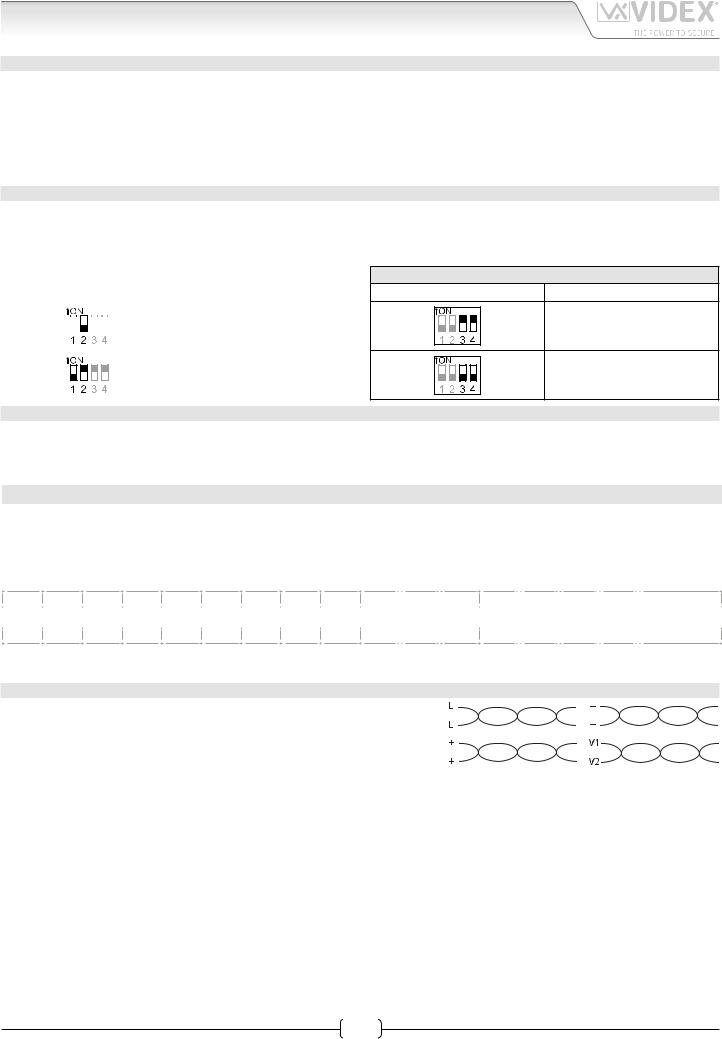
VIDEO MODE SW2
The video mode setup is carried out by the 4 way Dip-Switch accessible from the rear side of the videophone.
Switches 3 and 4 adjust the video signal impedance. When using more than one videomonitor in parallel (without a video splitter) put both switches in the OFF position on all but the last videomonitor (end of line).
|
|
|
|
|
|
|
|
|
VIDEO MODE |
|
Switches 1,2 |
|
Mode |
||||||||
|
|
|
|
|
|
|
|
|
|
Coax |
|
|
|
|
|
|
|
|
|
|
|
|
|
|
|
|
|
|
|
|
|
|
|
|
|
|
|
|
|
|
|
|
|
|
|
|
|
|
|
|
|
|
|
|
|
|
|
|
|
|
|
|
|
|
|
|
|
|
|
|
|
|
|
|
|
Balanced |
|
|
|
|
|
|
|
|
|
|
|
|
|
|
|
|
|
|
|
|
|
|
|
|
|
|
|
|
|
|
|
|
|
75 OHM VIDEO TERMINATION
Switches 3,4 |
Termination |
Enabled
Disabled
VIDEOMONITOR/INTERCOM ADDRESS, VIDEO MODE AND TERMINATION SETUP DSW1
Each intercom is addressed in binary (PHONE ID) using the 8 way dipswitches located on the rear of the unit. Each switch corresponds to one bit which can have a value 0 (OFF) or 1 (ON). Each bit corresponds to a decimal weight depending on the position: Switch 1 = decimal 1, 2=2, 3=4, 4=8, 5=16, 6=32, 7=64, 8=128. I.E. to set the address 37, put switches 1, 3 and 6 on (1+4+32=37).
|
|
|
|
|
|
SWITCHES |
|
|
|
|
|
|
|
|
DECIMAL WEIGHT |
|
|
|
ADDRESS |
|
|||||
8 |
|
7 |
|
6 |
|
5 |
|
4 |
|
3 |
|
2 |
|
1 |
128 |
64 |
32 |
16 |
8 |
|
4 |
2 |
1 |
|
|
OFF |
|
OFF |
|
OFF |
|
OFF |
|
OFF |
|
OFF |
|
OFF |
|
ON |
0 |
0 |
0 |
0 |
0 |
|
0 |
0 |
1 |
1 |
|
OFF |
|
OFF |
|
OFF |
|
OFF |
|
OFF |
|
OFF |
|
ON |
|
OFF |
0 |
0 |
0 |
0 |
0 |
|
0 |
1 |
0 |
2 |
|
OFF |
|
OFF |
|
OFF |
|
OFF |
|
OFF |
|
OFF |
|
ON |
|
ON |
0 |
0 |
0 |
0 |
0 |
|
0 |
1 |
1 |
3 |
|
OFF |
|
OFF |
|
OFF |
|
OFF |
|
OFF |
|
ON |
|
OFF |
|
OFF |
0 |
0 |
0 |
0 |
0 |
|
1 |
0 |
0 |
4 |
|
|
|
|
|
|
|
|
|
|
|
|
|
|
|
|
|
|
|
|
|
|
|
|
|
|
|
OFF |
|
OFF |
|
ON |
|
OFF |
|
OFF |
|
ON |
|
OFF |
|
ON |
0 |
0 |
1 |
0 |
0 |
|
1 |
0 |
1 |
37 |
|
ON |
|
OFF |
|
ON |
|
ON |
|
OFF |
|
ON |
|
OFF |
|
OFF |
|
|
1 |
1 |
|
|
1 |
0 |
0 |
180 |
|
|
|
|
|
|
|
|
1 |
0 |
0 |
|
|
||||||||||||||
CABLING 6478 USING CAT.5 CABLE* Connections:
• One pair must be used to double up the BUS line “L”;
• One pair must be used to double up the power supply ground. The bus ground must be connected with power supply ground (“GNDV” & “–”);
•One pair must be used to double up the positive power supply +20V;
•One pair must be used for the video signals “V1” and “V/V2”;
•A link is required between “12Vo” & “12Vi”;
•An additional PSU Art. 893N1 is required every 50 videomonitors installed in the system.
Max Distance**: 70 metres.
System type: Audio/video door entry systems.
*When this cable is used, in case more videophones are connected in parallel in the same apartment, a local power supply for additional videophones is required.
**By max distance we mean the maximum distance between the door panel and the furthest videophone/intercom
|
3 |
Art. 6478 - Installation instructions |
66251320-EN - V1.4 - 15/06/16 |

6400 Series
Art. 6478 4.3" hands free colour display videophone
ART. 6478 - SIGNALS
+VD |
12Vdc output to supply coax video distributor Art. 894N |
|||
+20 |
Video power supply 17÷20Vdc |
|
|
|
V1 |
BalancedvideosignalV1sync.(balancedvideosignalmode) |
|||
V/V2 |
BalancedvideosignalV2sync.(balancedvideosignalmode) |
|||
Composite video signal (coax video signal mode) |
||||
|
||||
GNDV |
Video power supply ground reference |
|||
L |
BUS line |
|
|
|
– |
BUS line ground reference |
|
|
|
LB |
Local bell input (active low) |
|
|
|
AL |
Alarm input (active low) |
|
|
|
DOL |
12Vdc input to supply Aux LED |
|
|
|
EXTC |
Call tone output for extension sounder (Art. 512A) |
|||
SW |
Service button connection |
|
Max 24 Vdc |
|
SW |
Service button connection |
|
50mA |
|
12Vo |
+12Vdc stabilized output |
|
|
|
12Vi |
Stand-by +12Vdc power supply input |
|
|
|
– |
Power supply ground input / coax video ground |
|||
VM |
Auxiliary input 200mA 12Vdc for |
video memory |
||
(Art. 6478/MV) |
|
|
||
|
|
|
||
Art. 6478 - Installation instructions
TECHNICAL SPECIFICATION
Working Voltage: |
17÷20Vdc |
Power Consumption: |
Standby: 10mA |
|
During a conversation: 150mA |
Working Temperature: |
Max: 250mA |
-10°C +50°C |
4
66251320-EN - V1.4 - 15/06/16
 Loading...