

Page 1
Kristallo Series
106
71
29 839
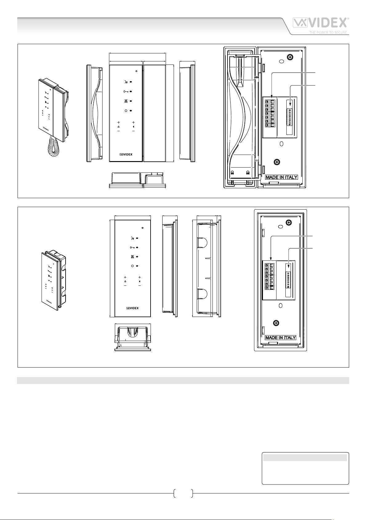
Art.KRA78-KRA76 Handsfree intercom
Fig. 1 Art.KRA76
63
42
182
29
DOL
SB
AL
LB
L
_
12Vin
SW1
ON
190
189
70
Fig. 2 Art.KRA78
DESCRIPTION
Intelligent Hands free intercom for the VX2200 digital system with touch sensitive buttons for “door open/concierge call”, “answer/
camera recall”, “privacy” and “service” plus 4 buttons for volume adjustment and programming plus 4 LEDs related to the intercom
operation. For the surface version only (Art.KRA76), a handset can also be used in addition to the handsfree mode.
The following programmable options are available:
• Call tone volume.
• Speech volume.
• Intercom address (from 1 to 180).
• Privacy duration (from 30 minutes to 20 hours or unlimited).
• Call melodies (9 available).
• Number of rings (from 1 to 9).
• Intercommunication mode/ Extension ID (from rmware release 2.0 and later).
Additionally the Kristallo has an input for local door bell and alarm.
DOL
SB
AL
LB
L
_
12Vin
SW1
ON
LEGEND
Connection terminals
8 way dip switch bank to set
videophone address
Art.KRA78-KRA76 - Installation instructions
1
66250930-EN - V2.2 - 15/01/16
Page 2
Kristallo Series
Art.KRA78-KRA76 Handsfree intercom
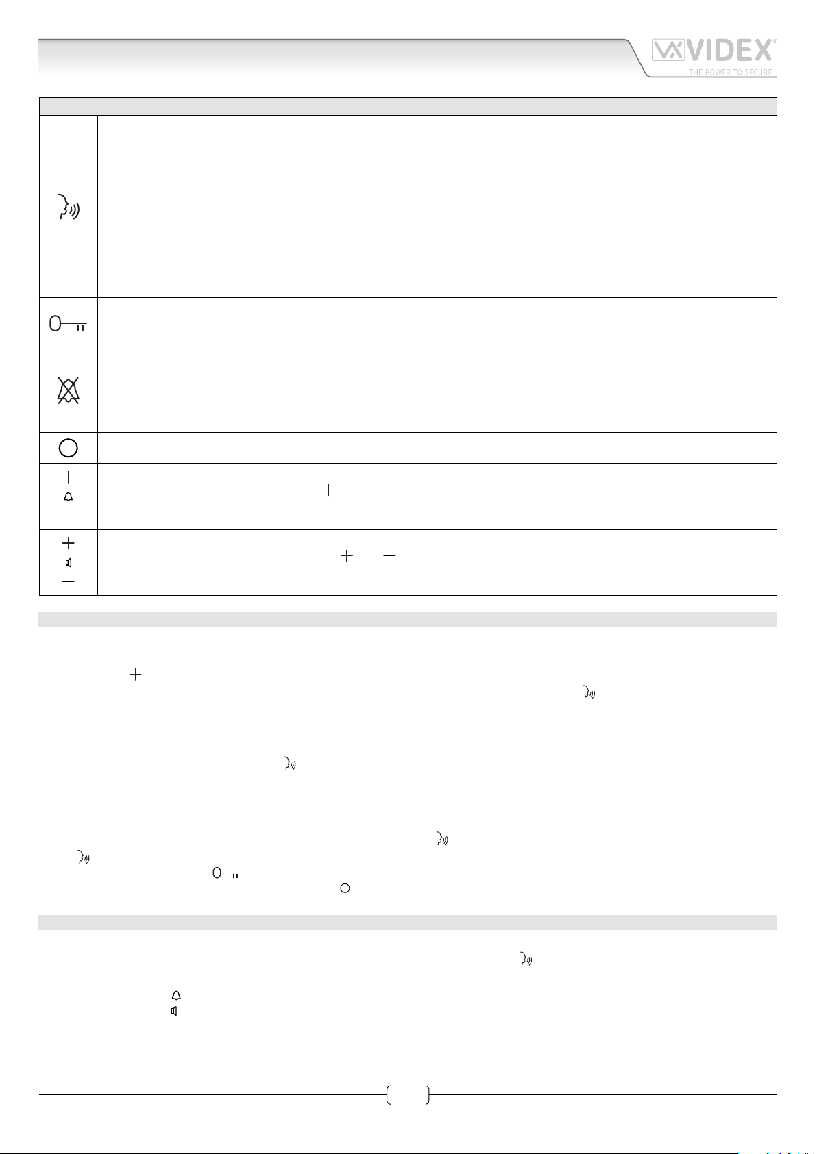
PUSH BUTTONS AND CONTROLS
• Press this button during an incoming call to open the speech in half duplex mode allowing free speech with the caller
in both directions (The related LED will illuminate).
• During a conversation, momentary operation of this button will end the call. The LED next to the button will switch
o. The system will automatically switch o when the conversation time expires.
• Press and hold this button (more than 1 second), during an incoming call or a conversation in progress, to allow the
user to answer a call from a visitor at the door station in SIMPLEX speech mode (The related LED will ash rapidly):
releasing the button will allow the user to listen to the visitor (The LED will ash slowly). Press and hold the button
when you talk to the visitor and release the button when you listen to the visitor.
• When the system is in standby, (No calls on the system) operation of this button will open the speech to the door
station (Only when the recall facility is enabled). The related LED will illuminate. Press as many time as the ID value of
the door panel to connect to.
• During a conversation, operation of this button will release the door from where the call originated. This will be conrmed by
an acoustic tone. If terminal “DL” is connected, the “door open” LED next to the button will also be illuminated.
• When the system is in stand-by, a button press will book a call to the concierge (If available)
• When the system is in stand-by, press this button to enable the service for the programmed time: the related LED will
illuminate to signal the service enabled. During an incoming call, with the service enabled, the device does not emit
any acoustic signal. The service is disabled when the programmed time expires or pressing again the button.
• When the system is in stand-by, keep pressed this button until the unit emit a beep and the related LED switches ON
to enter to privacy duration programming menu.
Press this button to enable the active low output “SB” for 2 seconds. The related LED illuminates and the intercom emits two beep.
When the system is in stand-by, press “ ” or “ ” (the intercom emits a beep) to increase or decrease the volume level
of the call tone: two short beeps signal the maximum or minimum level reached.
When intercom is in conversation, press “ ” or “ ” (the intercom emits a beep) to increase or decrease the volume
level of the speech: two short beeps signal the maximum or minimum level reached.
OPERATION
DURING STANDBY
Intercommunication
Press the right “
the same apartment or between dierent apartments) of the videophone/intercom to call. The “
RECEIVING A CALL
During a call:
• To answer in hands free mode press the “
DURING THE CONVERSATION
During the conversation:
• To switch from hands free to push to talk mode, keep pressed the “
the “ ” button to talk to the visitor (the LED ashes quickly) and release the button (the LED ashes slowly) to listen to the visitor;
• To open the door press the “ “ button;
• To enable the secondary service keep pressed the “ ” button until the conrmation is received.
“ button as many time (1 to 9) as the PHONE ID or the EXT. ID (depending on the intercommunication mode i.e. In
” LED will ash with every press.
” button (or pick up the handset on model Art.KRA76);
” until the related LED starts to ash slowly. Keep pressed
UNIT INITIALIZATION
TO RESTORE FACTORY PRESET
Make a link between the “LB” and “–“ terminals, power up the system and wait until
Factory default settings:
• The melody volume “ ” (factory preset medium level);
• The speech volume “ ” (factory preset medium level);
• The melody (factory preset 1);
• The number of rings (factory preset 6);
• The privacy duration (factory preset never ending);
2
Art.KRA78-KRA76 - Installation instructions
LED ashes once then remove the link.
66250930-EN - V2.2 - 15/01/16
Page 3
Kristallo Series
Art.KRA78-KRA76 Handsfree intercom
• The intercommunication mode (factory preset extension ID 1 intercommunication inside the same apartment)
TO ENABLE ENTRANCE RECALL FUNCTION
Make a link between “A L” and “–“. Power up the system and wait until“
feature follow the same procedure, the LED “
Now, when the system is in standby (No calls on the system), operation of “
related LED will illuminate. Press as many time as the ID value of the door panel to connect to (i.e. to open the speech to the door
panel with ID 3, press 3 times the button “
PROGRAMMING
Before connecting the intercom to the system, it is important to set the intercom address by the 8 way dip-switch on the back of the
unit. All other programming must be made with the intercom connected, powered and in stand-by.
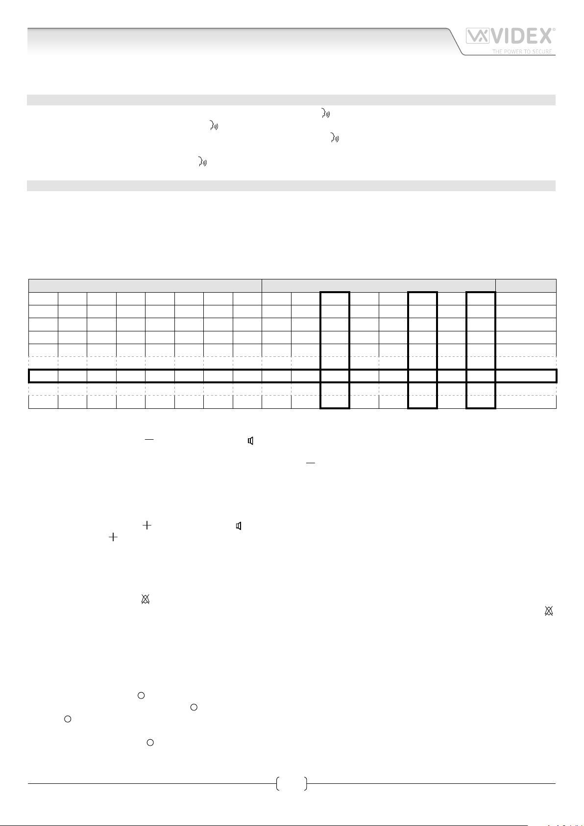
INTERCOM ADDRESS SETUP SW1 PHONE ID
Each device must be addressed in binary (PHONE ID) using the 8 way dipswitches located on the rear of the unit. Each switch correspond to one bit which can have a value 0 (OFF) or 1 (ON). Each bit corresponds to a decimal weight depending on the position:
Switch 1 = decimal 1, 2=2, 3=4, 4=8, 5=16, 6=32, 7=64, 8=128. I.E. to set the address 37, put switches 1, 3 and 6 on (1+4+32=37).
SWITCHES DECIMAL WEIGHT ADDRESS
8 7 6 5 4 3 2 1 128 64 32 16 8 4 2 1
OFF OFF OFF OFF OFF OFF OFF ON 0 0 0 0 0 0 0 1 1
OFF OFF OFF OFF OFF OFF ON OFF 0 0 0 0 0 0 1 0 2
OFF OFF OFF OFF OFF OFF ON ON 0 0 0 0 0 0 1 1 3
OFF OFF OFF OFF OFF ON OFF OFF 0 0 0 0 0 1 0 0 4
” will ash only once).
” ).
” LED ashes twice then remove the link (to disable the
” button will open the speech to the door station. The
OFF OFF ON OFF OFF ON OFF ON 0 0 1 0 0 1 0 1 37
ON OFF ON ON OFF ON OFF OFF 1 0 1 1 0 1 0 0 180
TO SET THE MELODY 9 AVAILABLE
• Keep pressed the button “
followed by a beep at the end;
• To listen and select another melody, press again the same button “ ” (a beep signals the end of play);
• When the required melody is reached, wait for the exit from melody programming to store the selected melody: the unit emits a
double beep and the LED switches o.
TO SET THE NUMBER OF RINGS FROM 1 TO 9
• Keep pressed the button “
• Press the button “ ” as many times as the number of rings to be set (each time the button is pressed the unit emits a beep);
• Once the required number is reached, wait for the exit from programming to store the new value: the unit emits a double beep
and the LED switches o.
TO SET PRIVACY DURATION FROM 30 MINUTES TO 20 HOURS OR NEVER ENDING
• Keep pressed the button “
• To set never ending, wait the exit from programming without pressing any button otherwise press one or more times the “ ”
button to set the required time (from 30 minutes to 20 hours) considering that each time the duration increases of 30 minutes
(i.e. to set 2 hours press 4 times the button);
• Once set the required number of rings, wait the exit from programming to store the new value set: the unit emits a double beep
and the LED switches o.
” (loudspeaker minus “ ”) until the service LED illuminates: the intercom play the current melody
” (loudspeaker plus “ ”) until the service LED illuminates and the intercom emits a beep;
” until the related LED illuminates and the intercom emits a beep;
TO SET AUXILIARY SERVICE DURATION
1. Press and keep pressed “
the “SB“ output remains active): the “ “ LED turns on and the unit emits a “beep“;
2. Press “ “ button as many seconds as required for the activation: the unit emits a “beep“ every time the button is pressed. I.E.:
press 30 times for 30 seconds. Default value: 2 seconds. Max value 99 seconds;
3. Wait for some seconds: the “ “ LED turns o and the unit emits a double “beep“ that conrms the new setting is properly stored;
4. The unit returns to stand-by mode.
Art.KRA78-KRA76 - Installation instructions
“ button for 5 seconds to enter auxiliary service duration programming mode (the time during which
3
66250930-EN - V2.2 - 15/01/16
Page 4

Kristallo Series
Art.KRA78-KRA76 Handsfree intercom
INTERCOMMUNICATION MODE AND EXTENSION ID. SETUP
1. Press and keep pressed “
the unit emits a “beep“;
2. Two intercommunication options are available:
» To enable intercommunication between dierent apartments (units with dierent PHONE ID) press nothing to enable
“APT. MODE”: this enables intercommunication among devices in dierent apartments having PHONE IDs from 1 to 9;
» To enable intercommunication between extensions in the same apartment (units with the same PHONE ID but with dierent
Extension ID) press the “ “ button as many times (1 to 9) as the value of the Extension ID to set for this intercom. this enables intercommunication between devices in the same apartment having EXTENSION IDs from 1 to 9;
3. Wait for some seconds: the “
4. The unit returns to stand-by mode.
“ button for 5 seconds to enter intercommunication mode and extension ID setup: the “ ” LED turns on and
” LED turns o and the unit emits a double “beep“ which conrms the new setting is properly stored;
TERMINALS
DOL 12Vdc input to supply “door open” LED
Open collector output (active low) for service call
button. When the monitor is switched on, keep
SB
pressed the “ ” button until the service is enabled.
Once enabled the output remains active for 2s approx.
Max 24V - 100mA dc.
Active low input for alarm signal. When active, the
system sends the alarm to the concierge if installed
AL
and enables the Art. 512DR if installed and properly
congured for the alarm management
LB
Active low input for local call “Local Bell”
L
BUS DATA line input
–
BUS Ground line input
12Vin
Stand-by +12Vdc power supply input
TECHNICAL SPECIFICATION
Power supply voltage: 12÷14Vdc
Power consumption: Stand-by: 6mA max (on 12Vdc)
Operating: 200mA Max (on 12Vdc)
Working temperature: -10° +50° C
Art.KRA78-KRA76 - Installation instructions
4
66250930-EN - V2.2 - 15/01/16
Page 5

Kristallo Series
Art.KRA78-KRA76 Handsfree intercom
Art.KRA78-KRA76 - Installation instructions
5
66250930-EN - V2.2 - 15/01/16
Page 6

Kristallo Series
Kristallo Series Flush and surface intercoms wall mounting instructions
135cm
Fig. 1
Fig. 3
Fig. 2
Fig. 4
135cm
Fig. 5 Fig. 6 Fig. 7
Fig. 8
Fig. 9
Fig. 10
6
Art.KRA78-KRA76 - Installation instructions
66250930-EN - V2.2 - 15/01/16
Page 7

Kristallo Series
Kristallo Series Flush and surface intercoms wall mounting instructions
FLUSH KRISTALLO INTERCOM MOUNTING INSTRUCTIONS
1. Protect the holes to x the intercom to the ush mounting box then embed the ush mounting box in line with the wall in vertical
position at 135cm height from the oor as shown in Fig. 1;
2. As shown in Fig. 2, connect the wires using a at screw driver then setup the dip-switches as per provided connection diagram
or instruction sheet.
3. As shown in Fig. 3, once the wires are connected, x the intercom to the ush mounting box using a Phillips screwdriver and the
two screws provided.
In order to avoid malfunctions, please do not over tighten the xing screws shown in Fig. 3.
4. Once the intercom is xed to the ush mounting box, place the front plate against the intercom by inserting the hooks in the
corresponding openings and hook the plate by pushing it down as shown in Fig. 4.
5. Test the system for correct operation.
SURFACE KRISTALLO INTERCOM MOUNTING INSTRUCTIONS
1. As shown in Fig. 5, place the intercom against the wall at 135cm height from the oor and mark the xing holes. Make the holes
(5mm diameter) and insert the provided wall plugs as shown in Fig. 6.
2. As shown in Fig. 7, connect the wires using a at screw driver then setup the dip-switches as per provided connection diagram
or instruction sheet.
3. As shown in Fig. 8, once the wires are connected, x the intercom to the wall using a Phillips screwdriver and the two screws
provided.
In order to avoid malfunctions, please do not over tighten the xing screws shown in Fig. 8.
4. Once the intercom is xed to the wall, place the front plate against the intercom by inserting the hooks in the corresponding
openings and hook the plate by pushing it down as shown in Fig. 9 and hang the handset as shown in Fig. 10.
5. Test the system for correct operation.
TOUCH SENSITIVE KEYS ADJUSTMENT
Cleansing the panel with the plate on or removing the plate for any reason may cause the touch sensitive buttons to lose their adjustment. If you detect any malfunctions, we suggest you proceed as follows:
• Remove the front plate doing the contrary of what is shown in Fig. 4 and Fig. 9;
• Touch the touch sensitive
prox 5 seconds);
• Hang up the front plate as shown in Fig. 4 and Fig. 9 before the display turns o;
• When the LED turns o the setting is done and the system is ready for use.
button area (the third of the four areas aligned in vertical way) until the relevant LED turns on (ap-
Art.KRA78-KRA76 - Installation instructions
7
66250930-EN - V2.2 - 15/01/16
Page 8

MANUFACTURER
The product is CE marked demonstrating its conformity and is for distribution
VIDEX ELECTRONICS S.P.A.
Via del Lavoro, 1 - 63846 Monte Giberto (FM) Italy
Tel (+39) 0734 631669 - Fax (+39) 0734 632475
www.videx.it - info@videx.it
CUSTOMER SUPPORT
All Countries:
VIDEX ELECTRONICS S.P.A.
www.videx.it - technical@videx.it
Tel: +39 0734-631669 - Fax: +39 0734-632475
UK Customers:
VIDEX SECURITY LTD
www.videx-security.com
Tech Line: 0191 224 3174 - Fax: 0191 224 1559
Main UK oce:
VIDEX SECURITY LTD
1 Osprey Trinity Park
Trinity Way
LONDON E4 8TD
Phone: (+44) 0870 300 1240
Fax: (+44) 020 8523 5825
www.videx-security.com
marketing@videx-security.com
Greece oce:
VIDEX HELLAS Electronics
48 Filolaou Str.
11633 ATHENS
Phone: (+30) 210 7521028
(+30) 210 7521998
Fax: (+30) 210 7560712
www.videx.gr
videx@videx.gr
Northern UK oce:
VIDEX SECURITY LTD
Unit 4-7
Chillingham Industrial Estate
Chapman Street
NEWCASTLE UPON TYNE - NE6 2XX
Tech Line: (+44) 0191 224 3174
Phone: (+44) 0870 300 1240
Fax: (+44) 0191 224 1559
Danish oce:
VIDEX DANMARK
Hammershusgade 15
DK-2100 COPENHAGEN
Phone: (+45) 39 29 80 00
Fax: (+45) 39 27 77 75
www.videx.dk
videx@videx.dk
Benelux oce:
VIDEX BENELUX
E3 Iaan, 93
B-9800 DEINZE
Phone: (+32) 9 380 40 20
Fax: (+32) 9 380 40 25
www.videxbenelux.be
info@videxbenelux.be
within all member states of the EU with no restrictions. This product follows
the provisions of the European Directives 2014/30/EU (EMC); 2014/35/EU
(LVD); 2011/65/EU (RoHS): CE marking 93/68/EEC.
 Loading...