

Page 1
ENG
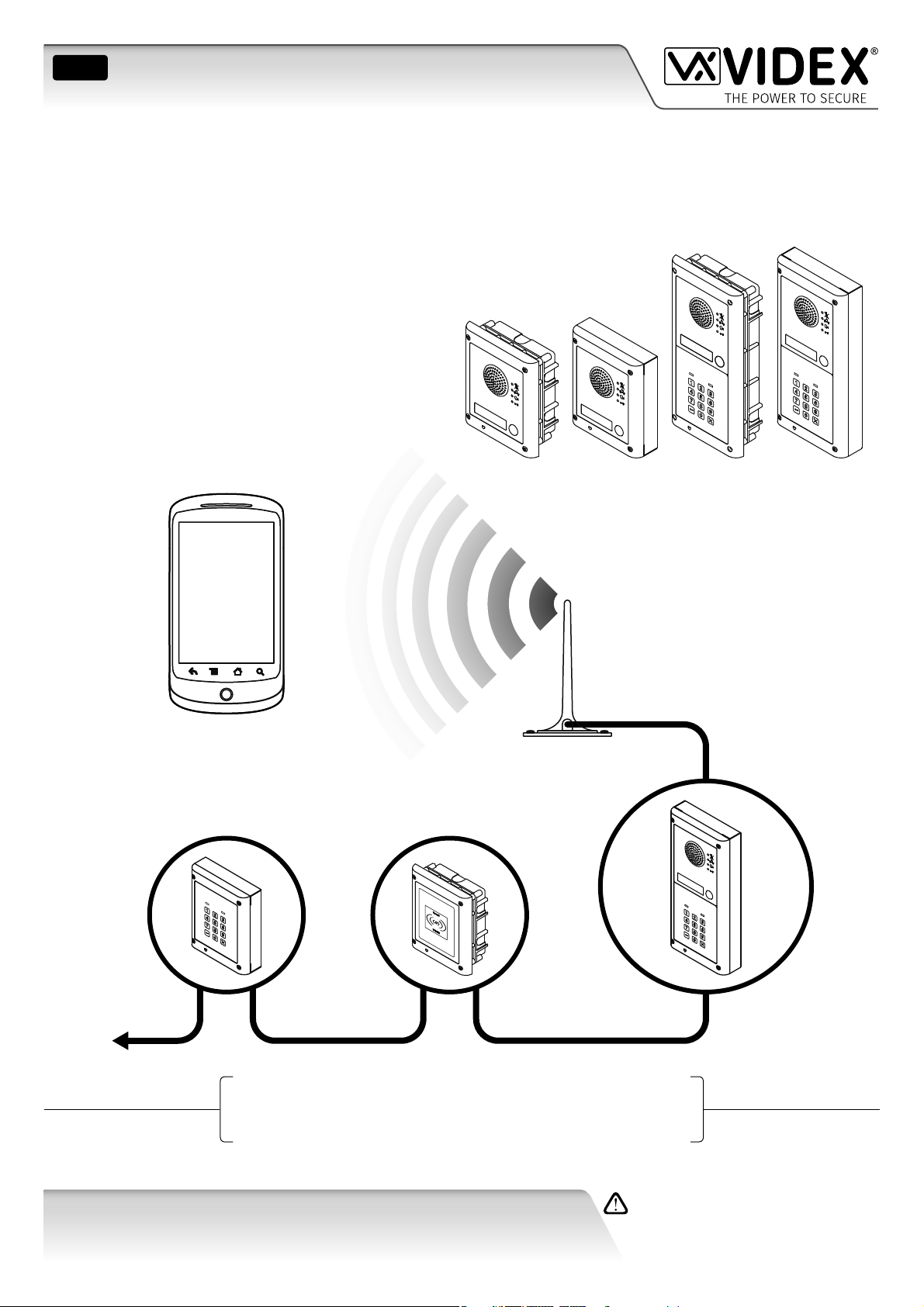
GSM AUDIO INTERCOM KIT
4000 Series GSM Audio Intercom with Proximity
GSM4K
GSM4KCR
66250754-EN
V1.1 - 27/06/19
Technical Manual
We recommend
This equipment is installed by a
Competent Electrician, Security or
Communications Engineer.
Page 2
4000 Series GSM Audio Intercom with Proximity
Declaration of Conformity
EU RoHS DECLARATION OF CONFORMITY
2G version
Telit Communications certies that the GL865-QUAD V3 (Quad Band GSM850/EGSM900/DCS1800/PCS1900 GPRS Wireless Module)
is in conformity with Directive 2011/65/EU of the European Parliament and the Council of 8th June 2011 on the restriction of the
use of certain hazardous substances in electrical and electronic equipment. The conformity with the applicable requirements of the
Directive 2011/65/EU has been demonstrated against the following harmonized standard: EN 50581:2012 Technical Documentation
for the assessment of electrical and electronic products with respect to the restriction of hazardous substances.
3G version
Telit Communications certies that the UL865-EUR (Dual Band 2G EGSM900/DCS1800 and Dual Band 3G FDD I/FDD VIII Wireless
Module) is in compliance with the essential requirements and other relevant provisions of European Directive 1999/5/EC (R&TTE).
The conformity with the essential requirements of the Directive 1999/5/EC has been demonstrated against the following harmonized
standards:
Article of Directive 1999/5/EC Harmonized Standard Reference
Health & Safety (R&TTE art. 3.1a)
EMC (R&TTE art. 3.1b)
RF Spectrum use (R&TTE art. 3.2)
EN 60950-1:2006 + A11:2009 + A1:2010 + A12:2011 + AC2011
EN 62311:2008
EN 301 489-1 V1.9.2
EN 301 489-7 V1.3.1
EN 301 489-24 V1.5.1
EN 301 511 V9.02
EN 301 908-1 V5.2.1
EN 301 908-2 V5.2.1
To comply with FCC RF exposure requirements, a separation distance of 20cm (7.87”) or more
must be maintained between the antenna of this product and all persons.
Separate FCC approval for this product is not required as it will be classed as a xed installation.
THIS PRODUCT IS NOT DESIGNED TO BE USED AS AN EMERGENCY CALL POINT.
MANUFACTURER
THE POWER TO SECURE
VIDEX ELECTRONICS S.P.A.
Via del Lavoro, 1 - 63846 Monte Gilberto (FM) Italy
Tel: (+39) 0734-631699 - Fax: (+39) 0734-632475
www.videx.it - info@videx.it
WARNING!
CUSTOMER SUPPORT
All Countries:
VIDEX ELECTRONICS S.P.A.
www.videx.it - technical@videx.it
Tel: +39 0734-631699 - Fax: +39 0734-632475
UK Customers:
VIDEX SECURITY LTD.
www.videxuk.com - tech@videxuk.com
Tech Line: 0191 224 3174 - Fax: 0191 224 1559
The product is CE marked demonstrating its conformity and is for distribution
within all member states of the EU with no restrictions. This product follows
the provisions of the European Directives 2014/30/EU (EMC); 2014/35/EU
(LVD); 2011/65/EU (RoHS): CE marking 93/68/EEC.
4000 Series GSM Audio Intercom - Technical Manual
- 2 -
66250754-EN - V1.1 - 27/06/19
Page 3

4000 Series GSM Audio Intercom with Proximity
Contents
Introduction .......................................................................................................................................................................................4
System Components and Available Versions ..................................................................................................................................6
Art. 4810 Technical Information .................................................................................................................................................... 12
Art. 4903 Technical Information .................................................................................................................................................... 14
Art. 4850R Technical Information .................................................................................................................................................. 18
Wiring Diagrams ............................................................................................................................................................................. 21
Auxiliary Inputs/Outputs ............................................................................................................................................................... 23
USB & RS485 Connection to a PC ................................................................................................................................................... 27
RS485 Network Connection ........................................................................................................................................................... 28
General Directions for Installation ................................................................................................................................................ 31
Fitting the SIM & Connecting Power ............................................................................................................................................. 34
Reset Procedure .............................................................................................................................................................................. 35
4000 Series Back Box Installation ................................................................................................................................................. 36
Programming the GSM Intercom .................................................................................................................................................. 38
The GSM Mobile App ...................................................................................................................................................................... 63
System Operation ........................................................................................................................................................................... 64
User Commands .............................................................................................................................................................................. 68
Additional User Information .......................................................................................................................................................... 69
User Management .......................................................................................................................................................................... 72
Troubleshooting ............................................................................................................................................................................. 74
General Information ....................................................................................................................................................................... 76
Notes ................................................................................................................................................................................................ 78
4000 Series GSM Audio Intercom - Technical Manual
- 3 -
66250754-EN - V1.1 - 27/06/19
Page 4

4000 Series GSM Audio Intercom with Proximity
Introduction
MANUAL INTRODUCTION
The information in this manual is intended as an installation and commissioning guide for the 4000 series GSM PRO audio intercom
system. This manual should be read carefully before the installation commences. Any damage caused to the equipment due to faulty
installation where the information in this manual has not been followed is not the responsibility of Videx Security Ltd.
It is recommended that the GSM audio intercom is installed by a competent electrician, security or communications engineer.
For UK customers Videx run free training courses for engineers who are unfamiliar or who have not installed this system before.
Technical help is also available for UK customers on tel: 0191 224 3174 during oce hours (8:30am - 5:00pm MON to FRI) or via e-mail:
tech@videxuk.com and for all overseas customers on tel: +39 0734 631669 or via e-mail: technical@videx.it.
A copy of this Technical Manual can also be downloaded from the Videx websites: For UK customers www.videxuk.com and for
overseas customers www.videx.it.
SYSTEM INTRODUCTION
The system is designed to work on the same technology as mobile phones. It enables a call to be made from an entry point (door,
gate etc), to any telephone number (mobile or land line). Up to 50 call buttons can be connected to the door panel, each able to
call four telephone numbers (if the rst is busy or not answered, the call can be diverted to up to three dierent numbers). The
standard GSM PRO intercom works on a 2G network. A 3G variant is also available (sux /3G to the part number e.g. Art.4810-0/3G,
Art.4810-1/3G etc.). Features of the system include:
• A dry contact relay output and push to exit input;
• Two open collector auxiliary outputs and two auxiliary inputs;
• Integrated Proximity Access Control (up to 1000 proximity fobs or cards can be stored, these fobs/cards when presented to
the nameplate window on the GSM PRO intercom or directly in front of the Art.4850R expansion reader will activate the
door/gate relay);
• Call progress speech annunciation and call progress LED indication;
• Dial to Open facility (this feature enables up to 1000 stored numbers to dial the GSM PRO intercom, the intercom panel will
not answer these calls, but will activate the door/gate relay without being charged for the call);
• Programmable call button timeband facility (a single timeband only);
• Programmable access control timeband facility (up to 10 timebands);
• Programmable free access timeband facility (up to 10 timebands);
• Up to 10 programmable access levels;
• Micro USB connection for ease of programming using the GSMSK PC software (version 4.0.0.0 or later);
• RS485 bus terminals for connecting additional ‘slave’ devices including coded keypads (Art.4903) and additional proximity
readers (Art.4850R), up to a maximum of 8 devices, also used for ease of programming using the GSMSK PC software;
• Integrated bootloader function for updating intercom panel rmware via the GSMSK PC software;
• Event logging system that can record up to 4000 events which can be downloaded via the GSMSK PC software;
• Remote event logging facility (unlimited events) which can be monitored in real time (also refer to additional notes on page
72 under user management).
Programming of the telephone numbers (primary no, divert no’s and dial to open no’s) and the additional features including
programming key fobs for the integrated proximity reader and additional proximity readers, programming access codes for
additional coded keypads, timebands, access levels etc. can be carried out via text messaging (refer to notes programming the
GSM intercom on pages 38 - 62) or using the GSMSK PC software (refer to the manual GSMSK_66251720_EN_V2-0 or later). Limited
programming features can also be programmed via the GSM mobile app, the Videx SMS Wizard (refer to notes the GSM mobile
app on page 63).
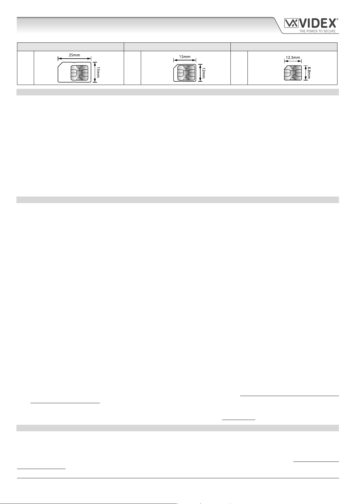
SIM CARD SELECTION
A SIM card is required for this product but not supplied by Videx. The GSM PRO intercom can only accept a standard size SIM card
(refer to the following SIM card size chart), both a micro-SIM and nano-SIM are not suitable. It is recommended to choose the SIM
card which has the best coverage for the area in which the intercom panel will be installed. Both contract and ‘Pay as you go’ SIM
cards can be used, however if using a ‘Pay as you go’ we would recommend setting up an automatic top up to avoid running short
on credit and losing the use of the intercom panel. Alternatively if you already have a contract mobile phone it should be possible
to get a second SIM card and telephone number on the existing account. For more information contact the SIM card provider or
visit their website, as this service is not provided by Videx.
4000 Series GSM Audio Intercom - Technical Manual
- 4 -
66250754-EN - V1.1 - 27/06/19
Page 5
4000 Series GSM Audio Intercom with Proximity
Introduction
Standard SIM Micro-SIM Nano-SIM
; : :
NETWORK PROVIDER SELECTION
It is imperative that for the reliable operation of the system that the best network provider for the area is selected. Problems such as
network disconnection can occur if the provider has signal or interference problems for that area. We would recommend using a GSM
signal strength meter to survey the intended antenna location. Contact Videx for more information on where to purchase a tester.
For UK customers, as an initial check we also recommend visiting the ofcom website www.ofcom.org.uk and follow the onsite links to
their online mobile coverage tool (ofcom broadband and mobile checker app). This tool will advise on the best coverage for the main
network providers and other general queries that you may have about the service provider. For all overseas customers we suggest
consulting the website of the network provider that will be used to check the coverage in your area.
The antenna should always be mounted vertically at the highest point possible. Metal structures and sources of interference such as
power cables, control panels etc. can aect signals and so the antenna should be mounted away from these.
When registering a new SIM you may be asked for the IMEI number. This is the unique serial number of the GSM intercom. This
number is located internally on the main hardware chip inside the GSM PRO module. To obtain the IMEI number from the GSM
module refer to the programming notes obtain the GSM’s IMEI number on page 62.
PRECAUTIONARY ADVICE
• When mounting the GSM antenna, choose a location which is away from human interaction and away from the intercom panel.
Route the GSM antenna cable from the intercom panel so that it is separate from the power supply cables and microphone wire.
• Always ensure the power is switched OFF to the intercom panel before inserting or removing the SIM card.
• New SIM cards will need registering with the network service provider before they can be used. Full details of how this is done
can normally be found in the SIM card pack. It will normally require that the SIM card is inserted into a mobile phone, a number
dialled and instructions followed. While the SIM is in the mobile phone it would be a good time to disable any PIN codes, call
diverts, ring back and disable features such as voicemail and text alerts. Details of how to do this can be found on the SIM
card provider’s website or by calling their customer services. Recommended SIM card providers are: Vodafone, T-Mobile, O2
or Orange/EE. The 3 network can only be used on our 3G devices (Art.4810-0/3G, Art.4810-1/3G etc.), also refer to page 6.
• To be able to receive text messages from the intercom panel, the SIM card will require an SMS service centre number. This is
normally pre-installed on new SIM cards but if you are having trouble receiving SMS messages you will need to conrm this by
inserting the SIM card into a mobile phone and using the phones menu options to check it. If a number is not programmed then
it should be programmed while in the phone (the number can be obtained from the network service provider).
• Voicemail and text alerts must be switched OFF on the SIM card when using the dial in to release the door/gate feature. For
Vodafone and O2 this can be done while the SIM card is in the intercom panel. For Orange/EE, T-Mobile and other providers the
SIM card must be removed from the intercom panel, inserted into a mobile phone and the mobile phone menu instructions
followed. This procedure may vary from provider to provider of dierent countires, we suggest contacting your provider for
information.
• When storing the intercom panel’s telephone number in your own mobile phone avoid using an obvious name such as ‘Front
Door’, or ‘My Gate’ as this would make it easy to decipher if your phone was lost or stolen.
• The PIN request feature must be disabled on the SIM card before using it in the Intercom panel. It is likely on a new SIM card that
it will not be enabled but if it is, it will prevent the system from working at all.
• This product may not be suitable for installation in hospitals, health care facilities or in the presence of ammable gases or
liquids. Seek advice and authorisation before installing this product in these locations. This product is not designed to be used
as an emergency call point.
Network provider and services conguration codes mentioned in this manual are specic for the UK. For overseas customers please contact
the network provider of your country for the corresponding codes, however Videx oers no guarantee that any additional codes will work.
IMPORTANT NOTE ABOUT THE SIM
When using a pay monthly SIM card you can ask the service provider to put a spend limit (credit limit) on the account (Vodafone
call this service ‘spend checker’). This is to safeguard against possible problems which could result in a large phone bill at the end
of the month. Most network providers oer this service. You will need to either ring or e-mail them to set this up. Automatic top
ups should also have a monthly limit. We would suggest a limit of £50.00 which should be more than enough. This service is not
provided by Videx.
4000 Series GSM Audio Intercom - Technical Manual
- 5 -
66250754-EN - V1.1 - 27/06/19
Page 6
4000 Series GSM Audio Intercom with Proximity
System Components and Available Versions
DESCRIPTION
A system comprises of an intercom panel, power supply, SIM card (SIM card not provided by Videx) and antenna. The intercom panel
is part of the Videx 4000 series modular design allowing it to be customised to the installation requirements for example including
coded access, proximity access or including the correct number of call buttons (up to 50 call buttons).
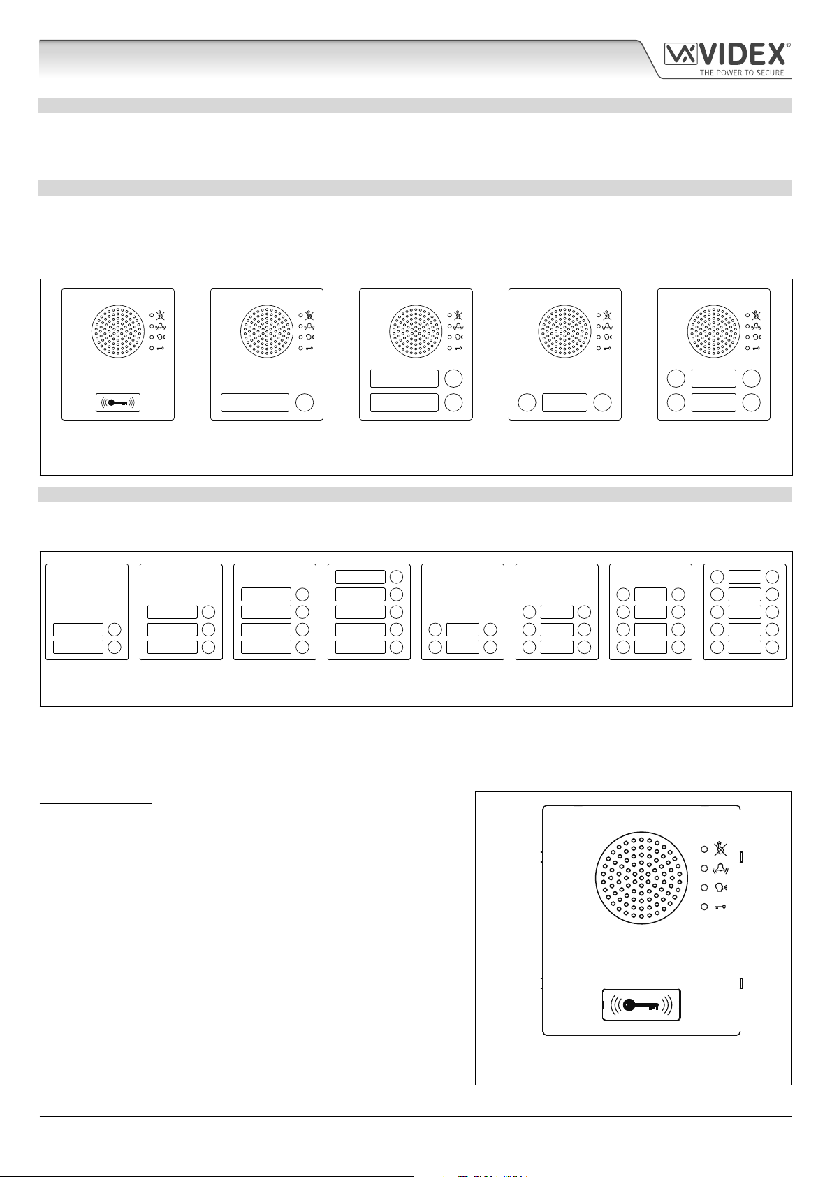
ART. 4810 GSM PRO INTERCOM AVAILABLE VERSIONS
The intercom panel can include any of the modules from the 4000 series range and uses the standard 4000 series surface and
ush mounting frames. The GSM PRO module is however essential and includes all the GSM communication electronics, SIM card
(supplied separately) and connections. The intercom module is available in a 0 button, 1 button, 2 button and 4 button conguration
(with all onboard buttons internally wired), as shown in Fig.1 along with their part numbers.
2
24
111313
Art. 4810-0,
Art. 4810-0/3G
Fig. 1
Art. 4810-1
Art. 4810-1/3G
Art. 4810-2
Art. 4810-2/3G
Art. 4810-1D
Art. 4810-1D/3G
Art. 4810-2D
Art. 4810-2D/3G
EXTENSION BUTTON MODULES
The GSM intercom module will accept up to 50 call buttons. Any of the standard 4000 series button modules can be used as shown
in Fig.2 along with their part numbers. Please note that button 1 is in the bottom right corner of the module counting up.
10
9
8
7
6
Art. 4842 Art. 4843 Art. 4844 Art. 4845 Art. 4842D Art. 4843D Art. 4844D Art. 4845D
Fig. 2
5
4
3
2
1
Button connections to the GSM module are shown in Fig.4 on page 7 (only the wiring of the button matrix is shown). It is important
to take care when using additional button modules with a GSM intercom module which also has onboard buttons. For example, an
intercom module with one button means the extension button module used must start wiring from button 2, an intercom module
with 2 buttons means the extension button module used must start wiring from button 3 and so on.
IMPORTANT NOTE: When extension button modules are being used
on systems where proximity access is required and the Art.4810-0 GSM
PRO module is used, the location of the onboard proximity reader is on
the front of the main GSM PRO module below the speaker, as shown in
Fig.3.
Standard versions of the GSM PRO (e.g. Art.4810-0 etc.) works on a 2G
network. A 3G variant is also available (see Fig.1 above) that works on a
3G network, sux /3G to the part no. (e.g. Art.4810-1/3G etc.).
4000 Series GSM Audio Intercom - Technical Manual
- 6 -
Art. 4810-0, Art.4810-0/3G
Fig. 3
66250754-EN - V1.1 - 27/06/19
Page 7

4000 Series GSM Audio Intercom with Proximity
System Components and Available Versions
BUTTON MATRIX WIRING
Fig. 4
BUTTON MODULE NOTES
If the GSM module has 1 button (Art.4810-1), the additional button module buttons should be wired starting from button number
2 (i.e. the rst button of the button module should be connected between a & 2, the next between a & 3 etc.).
If the GSM module has 2 buttons (Art.4810-2), the additional button module buttons should be wired starting from button number
3 (i.e. the rst button of the button module should be connected between a & 3, the next between a & 4 etc.).
If the GSM module has 4 buttons (Art.4810-2D), the additional button module buttons should be wired starting from button number
5 (i.e. the rst button of the button module should be connected between a & 5, the next between a & 6 etc.).
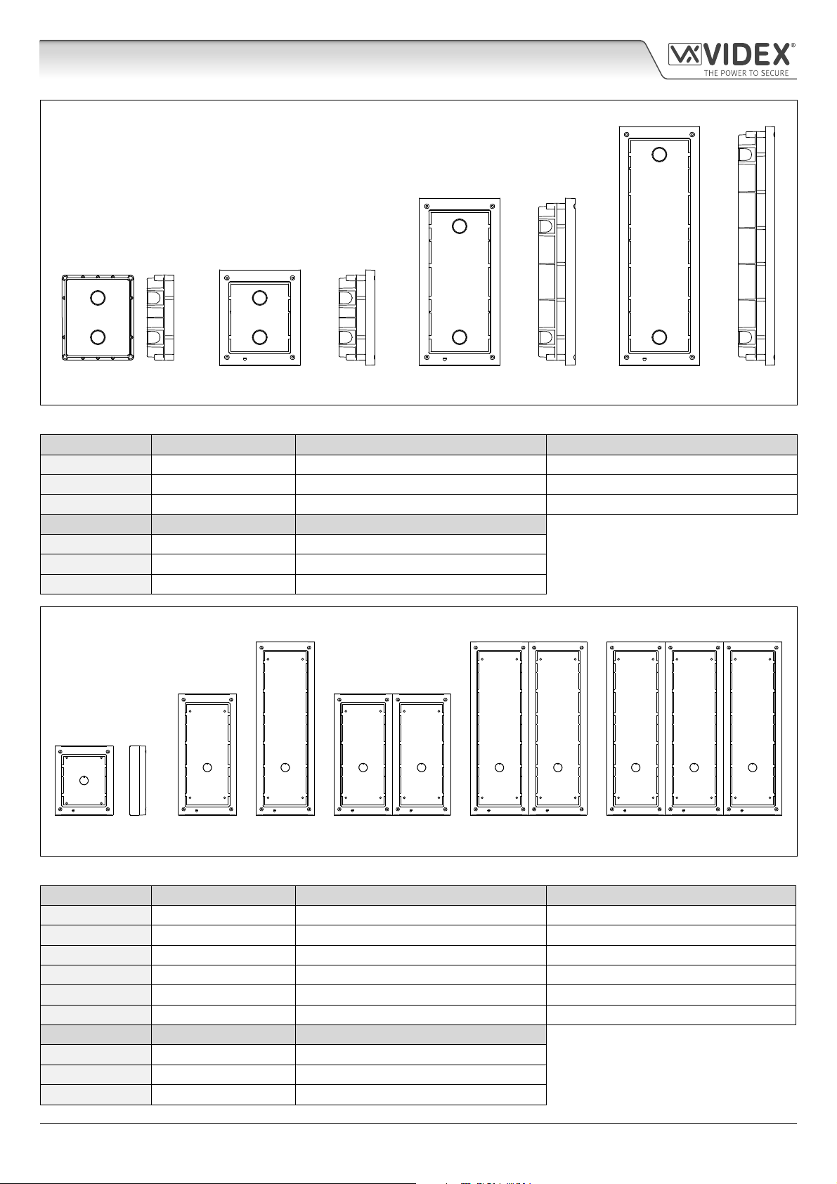
4000 SERIES BACK BOXES AND MOUNTING FRAMES
Both surface and ush back boxes and mounting frames are available. The size of the frame will depend on the number of modules
that make up the GSM4K/GSM4KCR kit. The last digit of the frame code indicates the number of modules it will take. Frames are
available in gun metal gray nish. The 4000 series mounting frames available are shown in Fig.5 (ush) and Fig.6 (surface) with the
following tables showing the back box dimensions including the part numbers and dimensions for optional ush and surface 4000
series rainshields.
4000 Series GSM Audio Intercom - Technical Manual
- 7 -
66250754-EN - V1.1 - 27/06/19
Page 8
4000 Series GSM Audio Intercom with Proximity
System Components and Available Versions
Flush Back Boxes and Mounting Frames
Art. 4851 Art. 4852 Art. 4853
Fig. 5
Flush Back Box Dimensions (inc. optional ush rainshields)
Part No. Housed Modules Front Frame (W x H x D) mm Back Box (W x H x D) mm
Art.4851 1 135 x 160 x 15.7 120 x 143 x 46
Art.4852 2 135 x 280.2 x 15.7 120 x 263.2 x 46
Art.4853 3 135 x 400.4 x 15.7 120 x 383.4 x 46
Part No. Module Size Rainshield Dimensions (W x H x D) mm
Art.4871 1 140 x 163 x 35
Art.4872 2 140 x 283 x 35
Art.4873 3 140 x 403 x 35
Surface Back Boxes and Mounting Frames
Art. 4881 Art. 4882 Art. 4883 Art. 4884 Art. 4886 Art. 4889
Fig. 6
Surface Back Box Dimensions (inc. optional surface rainshields)
Part No. Housed Modules No. of Columns Back Box (W x H x D) mm
Art.4881 1 1 135 x 160 x 43
Art.4882 2 1 135 x 280.2 x 43
Art.4883 3 1 135 x 400.4 x 43
Art.4884 4 2 270 x 280.2 x 43
Art.4886 6 2 270 x 400.4 x 43
Art.4889 9 3 405 x 400.4 x 43
Part No. Module Size Rainshield Dimensions (W x H x D) mm
Art.4891 1 140 x 163 x 62
Art.4892 2 140 x 283 x 62
Art.4893 3 140 x 403 x 62
4000 Series GSM Audio Intercom - Technical Manual
- 8 -
66250754-EN - V1.1 - 27/06/19
Page 9

4000 Series GSM Audio Intercom with Proximity
System Components and Available Versions
12VDC 2A POWER SUPPLY HDR1512
The Art. 4810 GSM PRO intercom is designed to work with power supplies in
the range of 12Vdc and should be capable of supplying a constant current of
no less than 1A. Both the GSM4K and GSM4KCR kits are supplied with a slim line
HDR-15-12, 12Vdc 1.25A power supply (refer to Fig.7).
ART. 432 GSM ANTENNA
Fig. 7
The Art.432 GSM antenna connects to the SMA female bulkhead connection on the
rear of the Art.4810 GSM PRO module. A GSM antenna with an SMA male connector
should be used (refer to Fig.8).
Antenna Parts
1. GSM antenna with magnetic base.
2. Self-threading screw (Ø3.5mm x 9.5mm).
3. Aluminium L bracket for mounting.
4. SMA male connector (cable length 2.5m).
5. Expansion type wall plugs (Ø6mm).
6. Self-threading screw (Ø4mm x 30mm).
7. Right angled SMA adapter.
IMPORTANT NOTE: An antenna must always be tted for the GSM module to
work. Always route the GSM antenna cable away from the microphone wires
and the power supply wires to avoid interference on the speech channels.
In instances where there is a tight tting space for the SMA male connector on
the antenna cable the right angled SMA adapter
7
can be used to help reroute
the cable down the back side of the GSM module.
SMA female bulkhead
connection on rear of
Art.4810 GSM PRO module
ART. 4903 CODELOCK
The Art.4903 codelock module (included as part of the GSM4KCR kits), see Fig.9,
can be powered from 12-24V AC or DC and includes 2 dry contact relay outputs
and two switched 0V push to exit inputs which can be used to trigger relay 1 &
2. It also includes an RS485 bus connection which can be linked to the Art.4810
GSM module and networked with other Art.4903 codelocks and/or Art.4850R
proximity devices (up to 8 devices in total).
When connected to the GSM PRO via RS485 it can operate up to 400 permanent
access codes (000-399) which can be assigned to trigger relay 1 or 2 or both. The
permanent codes can also have access levels and timebands assigned to them.
It can also operate up to 32 temporary codes. These codes can be between 4 - 8
digits long and are stored on the GSM PRO intercom. An additional two codes
(1 per relay) can be programmed directly via the keypad and are stored in the
codelock and not the GSM PRO module.
The relay time can be 01 - 99 seconds or set for latching (00). When in latching
mode, enter the code followed by ‘ENTER’
4000 Series GSM Audio Intercom - Technical Manual
to latch and to unlatch the relay.
- 9 -
Fig. 8
Fig. 9
66250754-EN - V1.1 - 27/06/19
Page 10
4000 Series GSM Audio Intercom with Proximity
System Components and Available Versions
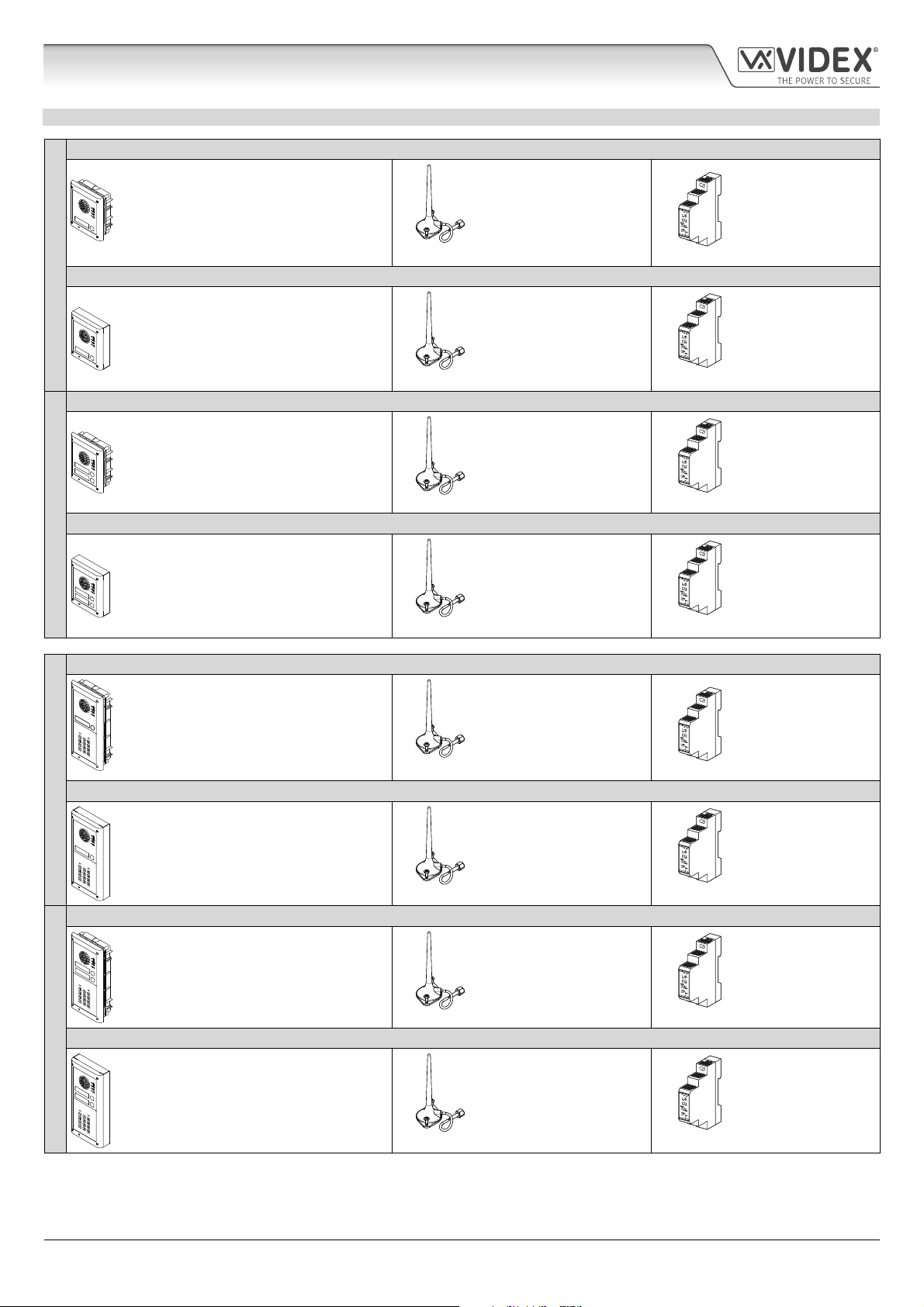
GSM INTERCOM AUDIO KITS
GSM4K-1 - ush mounting
1 Outdoor station composed of:
1 Art.4810-1: 1 button GSM (pro) unit
1 Art.4851: Flush mounting box
GSM4K-1S - surface mounting
1 Outdoor station composed of:
ONE WAY VERSIONS
GSM4K-2 - ush mounting
1 Art.4810-1: 1 button GSM (pro) unit
1 Art.4881: Surface mounting box
1 Outdoor station composed of:
1 Art.4810-2: 2 button GSM (pro) unit
1 Art.4851: Flush mounting box
1 GSM antenna
Art.432
1 GSM antenna
Art.432
1 GSM antenna
Art.432
1 Power supply
HDR-15-12
12Vdc 1.25A
1 Power supply
HDR-15-12
12Vdc 1.25A
1 Power supply
HDR-15-12
12Vdc 1.25A
GSM4K-2S - surface mounting
1 Outdoor station composed of:
1 Art.4810-2: 2 button GSM (pro) unit
TWO WAY VERSIONS
GSM4KCR-1 - ush mounting
GSM4KCR-1S - surface mounting
ONE WAY VERSIONS
GSM4KCR-2 - ush mounting
1 Art.4881: Surface mounting box
1 Outdoor station composed of:
1 Art.4810-1: 1 button GSM (pro) unit
1 Art.4903: 4000 series codelock
1 Art.4852: Flush mounting box
1 Outdoor station composed of:
1 Art. 4810-1: 1 button GSM (pro) unit
1 Art.4903: 4000 series codelock
1 Art.4882: Surface mounting box
1 Outdoor station composed of:
1 Art.4810-2: 2 button GSM (pro) unit
1 Art.4903: 4000 series codelock
1 Art.4852: Flush mounting box
1 GSM antenna
Art.432
1 GSM antenna
Art.432
1 GSM antenna
Art.432
1 GSM antenna
Art.432
1 Power supply
HDR-15-12
12Vdc 1.25A
1 Power supply
HDR-15-12
12Vdc 1.25A
1 Power supply
HDR-15-12
12Vdc 1.25A
1 Power supply
HDR-15-12
12Vdc 1.25A
GSM4KCR-2S - surface mounting
1 Outdoor station composed of:
1 Art.4810-2: 2 button GSM (pro) unit
TWO WAY VERSIONS
4000 Series GSM Audio Intercom - Technical Manual
1 Art.4903: 4000 series codelock
1 Art.4882: Surface mounting box
- 10 -
1 GSM antenna
Art.432
1 Power supply
HDR-15-12
12Vdc 1.25A
66250754-EN - V1.1 - 27/06/19
Page 11
4000 Series GSM Audio Intercom with Proximity
System Components and Available Versions
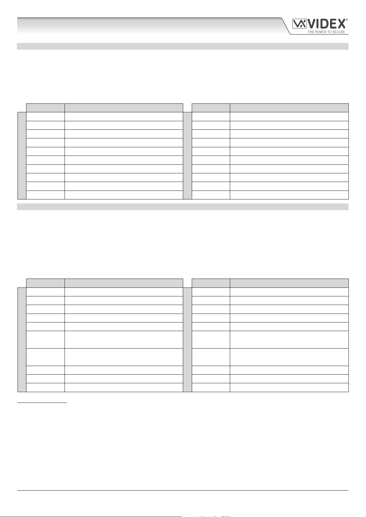
GSM4K AUDIO KITS
Additional GSM4K-n (ush) kit versions are available from 3 way kits up to 12 way kits: GSM4K-3 up to GSM4K-12. Each audio
kit comes with the appropriate Art.4810 GSM module, appropriate extension button module(s) and appropriate ush back box
depending on the GSM4K-n kit required (where n = the number of call buttons), refer to table below.
Additional GSM4K-nS (surface) kit versions are available from 3 way kits up to 12 way kits: GSM4K-3S to GSM4K-12S. Each audio
kit comes with the appropriate Art.4810 GSM module, appropriate extension button module(s) and appropriate surface back box
depending on the GSM4K-nS kit required (where n = the number of call buttons), refer to table below.
Kit No. Outdoor station composed of: Kit No. Outdoor station composed of:
GSM4K-3 1 Art.4810-0; 1 Art.4843; 1 Art.4852
GSM4K-4 1 Art.4810-0; 1 Art.4844; 1 Art.4852 GSM4K-4S 1 Art.4810-0; 1 Art.4844; 1 Art.4882
GSM4K-5 1 Art.4810-0; 1 Art.4845; 1 Art.4852 GSM4K-5S 1 Art.4810-0; 1 Art.4845; 1 Art.4882
GSM4K-6 1 Art.4810-1; 1 Art.4845; 1 Art.4852 GSM4K-6S 1 Art.4810-1; 1 Art.4845; 1 Art.4882
GSM4K-7 1 Art.4810-2; 1 Art.4845; 1 Art.4852 GSM4K-7S 1 Art.4810-2; 1 Art.4845; 1 Art.4882
GSM4K-8 1 Art.4810-0; 1 Art.4843; 1 Art.4845; 1 Art.4853 GSM4K-8S 1 Art.4810-0; 1 Art.4843; 1 Art.4845; 1 Art.4883
FLUSH
GSM4K-9 1 Art.4810-0; 1 Art.4844; 1 Art.4845; 1 Art.4853 GSM4K-9S 1 Art.4810-0; 1 Art.4844; 1 Art.4845; 1 Art.4883
GSM4K-10 1 Art.4810-0; 2 Art.4845; 1 Art.4853 GSM4K-10S 1 Art.4810-0; 2 Art.4845; 1 Art.4883
GSM4K-11 1 Art.4810-1; 2 Art.4845; 1 Art.4853 GSM4K-11S 1 Art.4810-1; 2 Art.4845; 1 Art.4883
GSM4K-12 1 Art.4810-2; 2 Art.4845; 1 Art.4853 GSM4K-12S 1 Art.4810-2; 2 Art.4845; 1 Art.4883
GSM4K-3S 1 Art.4810-0; 1 Art.4843; 1 Art.4882
SURFACE
GSM4KCR AUDIO KITS
Additional GSM4KCR-n (ush) kit versions are available from 3 way kits up to 12 way kits: GSM4KCR-3 up to GSM4KCR-12. Each
audio kit comes with the appropriate Art.4810 GSM module, appropriate extension button module(s), Art.4903 codelock module
and appropriate ush back box depending on the GSM4KCR-n kit required (where n = the number of call buttons), refer to table
below.
Additional GSM4KCR-nS (surface) kit versions are available from 3 way kits up to 12 way kits: GSM4KCR-3S to GSM4KCR-12S. Each
audio kit comes with the appropriate Art.4810 GSM module, appropriate extension button module(s), Art.4903 codelock module
and appropriate surface back box depending on the GSM4KCR-nS kit required (where n = the number of call buttons), refer to table
below.
Kit No. Outdoor station composed of: Kit No. Outdoor station composed of:
GSM4KCR-3 1 Art.4810-0; 1 Art.4843; 1 Art.4903; 1 Art.4853
GSM4KCR-4 1 Art.4810-0; 1 Art.4844; 1 Art.4903; 1 Art.4853 GSM4KCR-4S 1 Art.4810-0; 1 Art.4844; 1 Art.4903; 1 Art.4883
GSM4KCR-5 1 Art.4810-0; 1 Art.4845; 1 Art.4903; 1 Art.4853 GSM4KCR-5S 1 Art.4810-0; 1 Art.4845; 1 Art.4903; 1 Art.4883
GSM4KCR-6 1 Art.4810-1; 1 Art.4845; 1 Art.4903; 1 Art.4853 GSM4KCR-6S 1 Art.4810-1; 1 Art.4845; 1 Art.4903; 1 Art.4883
GSM4KCR-7 1 Art.4810-2; 1 Art.4845; 1 Art.4903; 1 Art.4853 GSM4KCR-7S 1 Art.4810-2; 1 Art.4845; 1 Art.4903; 1 Art.4883
GSM4KCR-8
FLUSH
GSM4KCR-9
GSM4KCR-10 1 Art.4810-0; 2 Art.4845; 1 Art.4903; 2 Art.4852 GSM4KCR-10S 1 Art.4810-0; 2 Art.4845; 1 Art.4903; 1 Art.4884
GSM4KCR-11 1 Art.4810-1; 2 Art.4845; 1 Art.4903; 2 Art.4852 GSM4KCR-11S 1 Art.4810-1; 2 Art.4845; 1 Art.4903; 1 Art.4884
GSM4KCR-12 1 Art.4810-2; 2 Art.4845; 1 Art.4903; 2 Art.4852 GSM4KCR-12S 1 Art.4810-2; 2 Art.4845; 1 Art.4903; 1 Art.4884
1 Art.4810-0; 1 Art.4843; 1 Art.4845;
1 Art.4903; 2 Art.4852
1 Art.4810-0; 1 Art.4844; 1 Art.4845;
1 Art.4903; 2 Art.4852
GSM4KCR-3S 1 Art.4810-0; 1 Art.4843; 1 Art.4903; 1 Art.4883
GSM4KCR-8S
SURFACE
GSM4KCR-9S
1 Art.4810-0; 1 Art.4843; 1 Art.4845;
1 Art.4903; 1 Art.4884
1 Art.4810-0; 1 Art.4844; 1 Art.4845;
1 Art.4903; 1 Art.4884
IMPORTANT NOTE: The GSM audio kits listed above work on a 2G network. For the 3G variant remember to sux the kit part
no. with /3G, e.g. GSM4K-4/3G, GSM4KCR-6S/3G etc.
All GSM audio kits are supplied with a HDR-15-12 12Vdc, 1.25A slim line power supply and Art.432 antenna.
4000 Series GSM Audio Intercom - Technical Manual
- 11 -
66250754-EN - V1.1 - 27/06/19
Page 12
4000 Series GSM Audio Intercom with Proximity
Art. 4810 Technical Information
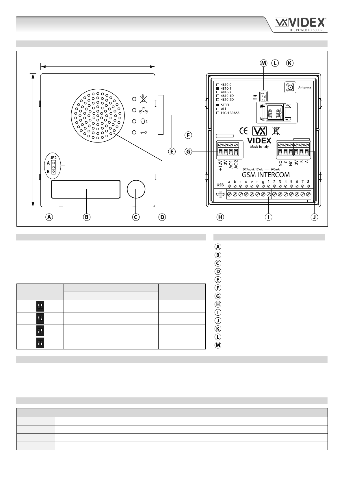
ART. 4810 GSM PRO MODULE
103mm
120mm
Internal jumper JP2
Nameplate LED illumination adjustment
R02A
GSM4K-3.0.2
RS485
Fig. 10
SPEAKER VOLUME ADJUSTMENT DIPSWITCH SETTINGS LEGEND
There are 2 dip-switches located on the back of the GSM module next to the
antenna connection, see Fig.10. They can be used to adjust the volume from
the door intercom speaker (see table below). Additionally, the volume can also
be adjusted during a call electronically via the telephone keypad (refer to user
command table on page 68).
Internal nameplate LED jumper (JP2)
Nameplate and proximity access reader
Call button
Intercom speaker
Call progress LED's
Dip-Switch
ON
12
ON
12
ON
12
ON
12
Dip-Switch Status
Dip No.1 Dip No.2
Gain (dB)
ON ON 6
ON OFF 12
OFF ON 18
OFF OFF 23.5
Current rmware version (GSM4K X.X.X)
Power input and auxiliary terminals
Micro USB connection
Button matrix terminals
Relay output and RS485 bus terminals
Antenna connection
SIM card holder
Speaker volume dip-switches
NAMEPLATE ILLUMINATION JUMPER JP2
The nameplate LED illumination jumper JP2 is located behind the GSM module’s front facia, as shown in Fig.10. To access the
jumper the facia must be removed and the jumper can be adjust as required. When JP2 is set in position A (upper 2 pins) the LED
is set for bright illumination, when JP2 is set in position B (lower 2 pins) the LED is set for low illumination and if JP2 is completely
removed this will disable the nameplate LED’s.
TERMINAL CONNECTIONS
Terminal Description
+12V 12 - 24Vdc or ac power.
0V 0V ground power.
AO1 Auxiliary output 1 (open collector, 150mA max.).
AO2 Auxiliary output 2 (open collector, 150mA max.).
4000 Series GSM Audio Intercom - Technical Manual
- 12 -
66250754-EN - V1.1 - 27/06/19
Page 13
4000 Series GSM Audio Intercom with Proximity
Art. 4810 Technical Information
terminals continued...
NO Normally open relay contact.
C Common relay contact.
NC Normally closed relay contact.
0V
B
A
a - g
RS485 bus terminals for permanent connection to a PC, also used to network with Art.4903 codelock and Art.4850R
proximity reader (up to 8 devices max.).
Button matrix for connecting up to 50 call buttons, PTE, and auxiliary inputs.
The PTE (push to exit button) connects across g-6.
1 - 8
Auxiliary 1 input connects across g-5 (activates AO1 when set to mode 01).
Auxiliary 2 input connects across g-4 (sends SMS message to master telephone number).
JP2 Nameplate window LED illumination adjustment. JP2 position A = LED bright,
JP2 position B = LED low, JP2 removed = LED disabled.
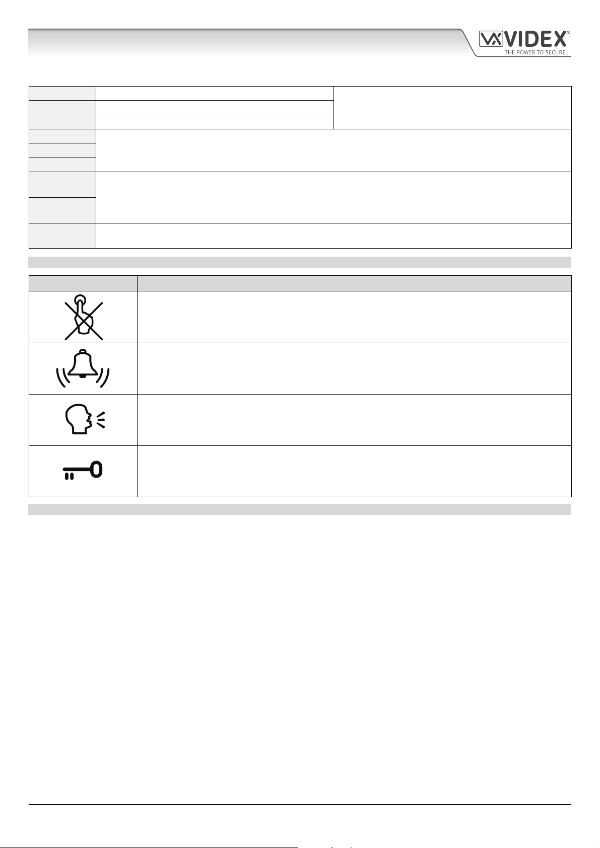
CALL PROGRESS LED’S
LED (sign) Description
The busy LED when illuminated, indicates that it is not possible to make a call because a call or a
conversation is in progress. The LED will be OFF when the system is in standby. If there is power on
the GSM intercom and the Art.432 antenna is not connected this LED will ash continuously until the
antenna is connected. The LED will ash while connecting to a network.
The call LED when illuminated, indicates that the call from the GSM intercom panel is in progress. The
LED will switch OFF when the call is answered or after the call time expires.
Relay contacts:
3A@24Vdc
3A@120Vac
The speak LED when illuminated, indicates that it is possible to speak because the call has been
answered. The LED will switch OFF at the end of a conversation when the telephone/mobile that has
been dialled hangs up or at the end of the call time.
The open LED when illuminated, indicates that the door lock (GSM relay) has been operated. It will
switch OFF at the end of the programmed “door opening” time. The LED will also illuminate and operate
the relay if a programmed key fob is presented to the onboard proximity reader (nameplate window).
TECHNICAL SPECIFICATION
Working Voltage: 12 - 24Vdc or ac +/- 10%
Standby Current: approx. 60mA
Max. Current: approx. 500mA (max.)
Call Buttons: up to 50 (max.)
Telephone Numbers per Button: 4 telephone numbers (1 primary, 3 diverts)
Dial to Open Numbers: up to 1000 (max.)
Proximity Access (fobs/cards): up to 1000 users (max.)
Coded Access: up to 400 permanent codes and 32 temporary codes (when used with Art.4903 via RS485 bus)
Call Progress LED's: 4 (busy, call, speak and open)
Programming Method: SMS messaging or PC software
RS485 Bus Connection: A, B and 0V
Push to Exit Input: 1 (push-to-make across terminals g-6)
Auxiliary Inputs: 2 (AO1 = across terminals g-5, AO2 = across terminals g-4)
Auxiliary Outputs: 2 (open collector output, switched 0V, 150mA max.)
Dry Contact Relay: C, NO and NC, 3A @ 24Vdc, 3A @ 120Vac
Event Logging: up to 4000 events (unlimited when using remote logging facility)
USB Port: micro USB
Timebands: 1 call button timeband; 10 access control and 10 free access timebands
Working Temperature: -10 +50
o
C
4000 Series GSM Audio Intercom - Technical Manual
- 13 -
66250754-EN - V1.1 - 27/06/19
Page 14
4000 Series GSM Audio Intercom with Proximity
Art. 4903 Technical Information
ART. 4903 CODELOCK MODULE
103mm
120mm
4903
STEEL
ALI
HIGH BRASS
MATTE
Note: Remove MOV
jumper completely
when using a relay to
trigger a gate controller.
MOV
NO2 NC2
NO1 NC1
RS485 BUS TERMINATION
Fig. 11
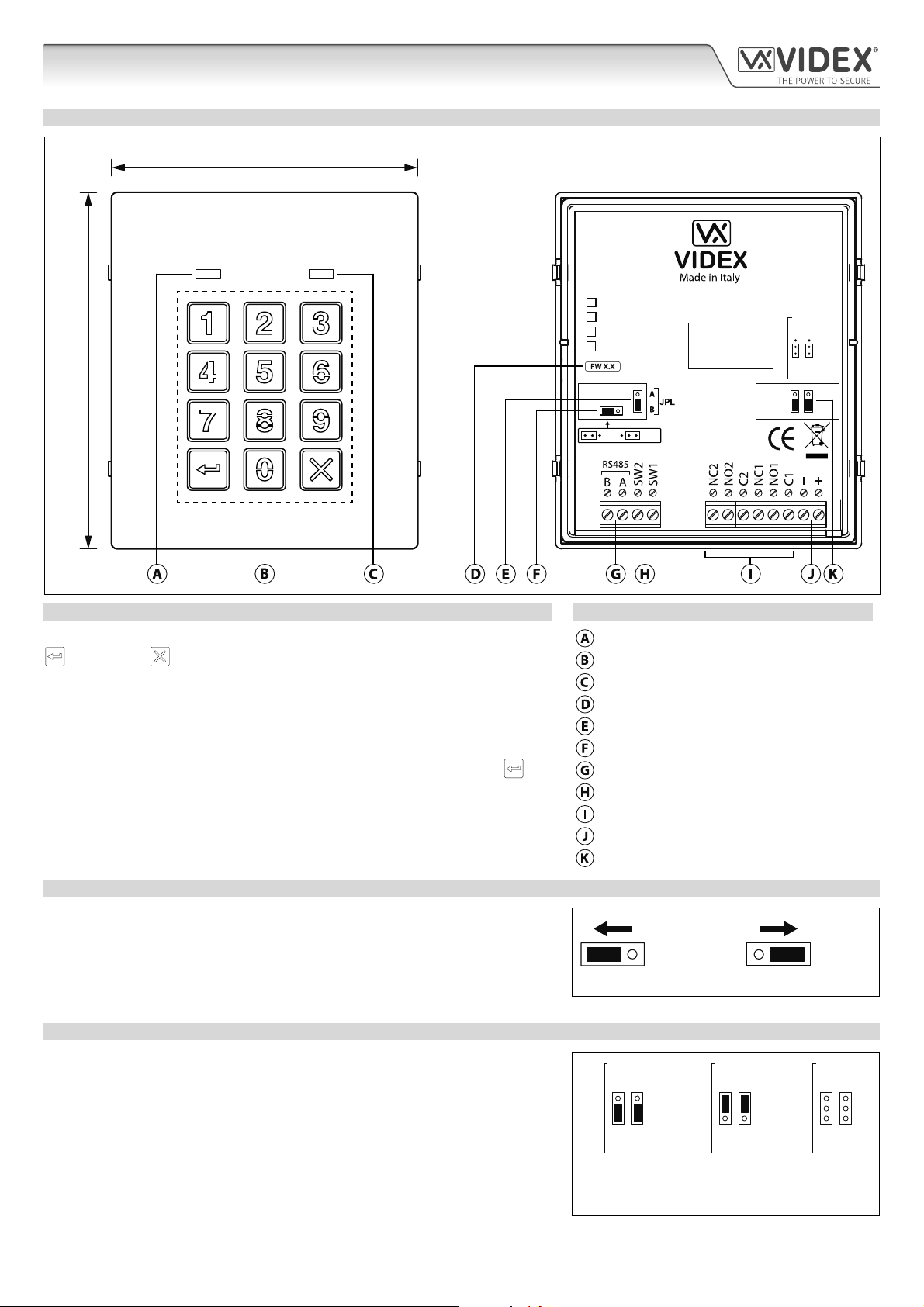
DESCRIPTION LEGEND
The module features 12 stainless steel buttons, backlit in blue (keys 0 - 9, ENTER
and CLEAR ), 2 LED’s (green LED = data, red LED = status indication)
for progress information during use and programming and a stainless steel or
aluminium front plate, see Fig.11. With two integral relays (RLY1 and RLY2) each
with common (C), normally open (NO) and normally closed (NC) connections
and two switched 0V push to exit inputs SW1 and SW2 to enable the external
triggering of the relays. Key presses are signalled acoustically while each button
press has a tactile feel. Entering the correct code followed by ENTER
will
activate the relevant relay.
Data LED (green)
Backlit (blue) key buttons
Status indication LED (red)
Current rmware version (FW X.X)
Back light adjustment jumper (JPL)
RS485 bus termination jumper (JP1)
RS485 bus terminals
PTE terminals (SW1 and SW2)
Relay terminals (RLY1 and RLY2)
Power input terminals
Back EMF protection (JP2 and JP3)
OFFON
RS485 BUS TERMINATION JUMPER JP1
The jumper JP1 on the rear of the keypad sets the RS485 bus termination when
connected to the Art.4810 GSM PRO or other RS485 devices. By default the
jumper is set to the ON position (across to the left). When more than one RS485
device is connected to the keypad in line on the RS485 bus terminals then the
jumper can be set to the OFF position (across to the right) and only set to the
ON (closed) position on the end of line device, see Fig.12.
RELAY BUILTIN BACK EMF PROTECTION JP2 AND JP3
The Art.4903 includes selectable back EMF protection (metal oxide varistors)
jumpers JP2 and JP3 for each relay (marked MOV) and are used to select the
protection type. When using a fail secure lock with connections C & NO the
jumper should be in the NO position. When using a fail open (safe) lock with
connections C & NC the jumper should be in the NC position, as shown in
Fig.13. When using the codelock to trigger a gate controller or another third
party controller the jumper should be removed completely (this disables the
protection on the relay).
4000 Series GSM Audio Intercom - Technical Manual
- 14 -
ON OFF
Fig. 12
NC2
NC1
MOV
NO2
NO1
NO position for fail
secure lock release
Fig. 13
NC2
NC1
MOV
NO2
NO1
NC position for fail
safe lock release
66250754-EN - V1.1 - 27/06/19
NC2
MOV
NO2
remove jumpers
for gate controls
NC1
NO1
Page 15
4000 Series GSM Audio Intercom with Proximity
Art. 4903 Technical Information
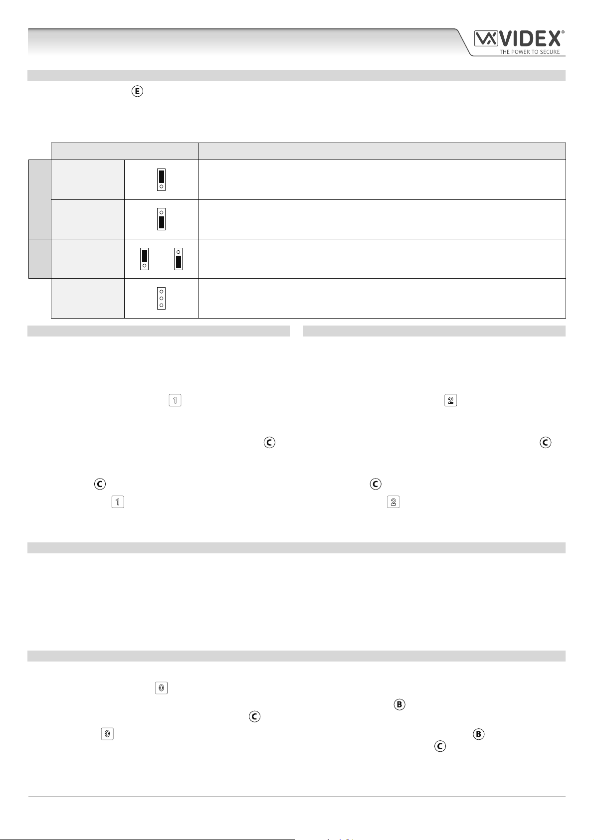
BACK LIGHT ADJUSTMENT JUMPER JPL
The jumper JPL (Fig.11,
brightness settings for the backlit buttons and two programming modes (mode 1 and 2) for the jumper.
The two modes that can be programmed change the functionality of the jumper JPL. The table below indicates the programming
mode, the position of the jumper and the operation of the backlit buttons.
Jumper Position Back light Operation
A
Mode 1
B
(default)
A or B
Mode 2
JPL removed in
either Mode
) is used to adjust the brightness and determine the operation of the backlit buttons. There are four
A
Back light OFF in standby. Full brightness when any buttons are pressed.
B
A
Back light on low brightness in standby. Full brightness when any buttons are pressed.
B
A
B
or
A
Back light on full brightness all of the time.
B
A
No back light, the back light is completely disabled.
B
PROGRAMMING MODE 1 DEFAULT MODE, JPL = B
Follow the steps below to set the codelock to mode 1:
1. Disconnect the power from the Art.4903 codelock;
2. Short out terminals - and SW2, see Fig.14, page 16;
3. Press and hold down button 1
and keep it pressed down
while the power is switched back ON;
4. When power is restored to the codelock wait for the module
to emit a single beep and the red status LED (Fig.11,
ash once;
5. Listen for the conrmation tone and wait for the red status
LED (Fig.11,
6. Release button 1
) to ash once again;
and remove the short between terminals
- and SW2, see Fig.15, page 16;
7. Set the jumper JPL to the desired position.
PROGRAMMING MODE 2
Follow the steps below to set the codelock to mode 2:
1. Disconnect the power from the Art.4903 codelock;
2. Short out terminals - and SW2, see Fig.14, page 16;
3. Press and hold down button 2
and keep it pressed down
while the power is switched back ON;
4. When power is restored to the codelock wait for the module
) to
to emit a double beep and the red status LED (Fig.11,
ash once;
5. Listen for the conrmation tone and wait for the red status
LED (Fig.11,
6. Release button 2
) to ash once again;
and remove the short between terminals
- and SW2, see Fig.15, page 16;
7. Set the jumper JPL to the desired position.
) to
BACK LIGHT AND BUTTON OPERATION
If the back light programming mode is set to mode 1 (with jumper JPL in either the A or B position) when a button is pressed on the
keypad the back light will switch to full brightness for approximately 10 seconds.
After this time the back light will either switch OFF or switch back to low brightness (depending on the jumper position) unless
another button has been pressed within the 10 second period in which case the back light will stay on full brightness for a further
10 seconds.
The exception to this is if the back light programming mode is set to mode 2, i.e. the back light will be on full brightness all of the
time or if the jumper is removed the back light will be disabled.
SETTING UP THE UNIT ID OF THE KEYPAD ID 1 8
1. First disconnect the power from the Art.4903 keypad, then short out terminals - and SW2 (Fig.14, page 16);
2. Press and hold down the 0
3. When power is restored to the keypad the backlit key buttons will illuminate (Fig.11,
button, keeping it pressed while the power is switched back ON;
). Wait for the keypad to emit a low
level tone then wait for the red status LED (Fig.11, ) to switch ON;
4. Release the 0
button then enter the unit ID required for the Art.4903 (1 - 8) using the keypad (Fig.11, ). The red status
LED will switch OFF and the keypad will play a short melody. Observe the red status LED (Fig.11, ) as this will ash as many
times as the unit ID being set (e.g. if the unit ID is set to ID.8 the red status LED will ash 8 times);
5. After the red status LED stops ashing remove the short between terminals - and SW2 (Fig.15, page 16) the unit ID has been set.
4000 Series GSM Audio Intercom - Technical Manual
- 15 -
66250754-EN - V1.1 - 27/06/19
Page 16
4000 Series GSM Audio Intercom with Proximity
Art. 4903 Technical Information
PROGRAMMING AS A STANDALONE KEYPAD
When using the Art.4903 as a standalone keypad the programming is the same as the programming of an Art.4800M keypad
(refer to programming guide and owchart below). All programming is carried out using the keypad. The programming menu is
protected by an ENGINEER’S CODE, the factory default of which is six times 1 (“111111”). This code can be changed to any 4 to 8
digit ENGINEER’S CODE during the programming and is used to gain entry to the programming menu only.
Each relay (RLY1 and RLY2) can be programmed with a 4 - 8 digit access code (one code per relay) and will activate the respective
relay for the programmed relay time (01 - 99 seconds or 00 for latching). The access code programmed is stored in the keypads
internal memory.
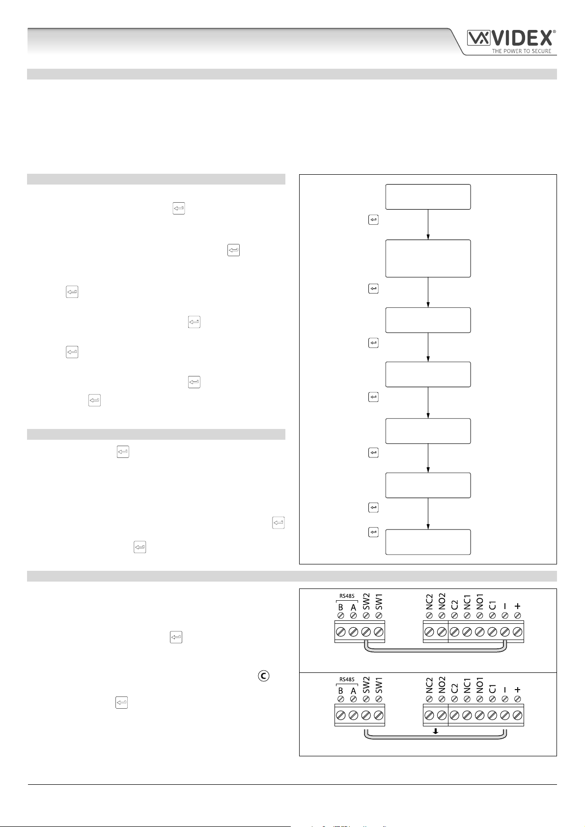
PROGRAMMING GUIDE
• Enter the ENGINEER’S CODE: rst time type six times 1 (111111
factory default) and press ENTER
to conrm, (the red LED
will illuminate);
• Conrm ENGINEER’S CODE: re-type the same code again or
type a new code (4 to 8 digits) then press ENTER
to conrm,
(melody);
• Enter the code (4 to 8 digits) to enable RELAY 1 then press
ENTER
to conrm, (melody);
• Enter the RELAY 1 operation time (2 digits 01 to 99, i.e. 05 = 5
seconds, 00 = latch) then press ENTER
to conrm, (melody);
• Enter the code (4 to 8 digits) to enable RELAY 2 then press
ENTER
to conrm, (melody);
• Enter the RELAY 2 operation time (2 digits 01 to 99, i.e. 05 = 5
seconds, 00 = latch) then press ENTER
• Press ENTER
twice again to exit programming (melody);
to conrm, (melody);
• The system is ready to use (the red LED will switch OFF).
PROGRAMMING NOTES
• Pressing the ENTER
button twice during the programming
process, without changing any parameters, will exit from the
programming menu.
• When entering a relay code it must be dierent from the
ENGINEER'S CODE.
• To latch the relay type in the access code then press ENTER
to conrm. To unlatch the relay type in the same access code
again then press ENTER
to conrm.
ENTER THE
“ENGINEER’S CODE”
Press ENTER
(red LED ON)
CONFIRM
OR CHANGE
“ENGINEER’S CODE”
Press ENTER
(melody)
ENTER
“ACCESS 1 CODE”
Press ENTER
(melody)
ENTER
“ACCESS 1 TIME”
Press ENTER
(melody)
ENTER
“ACCESS 2 CODE”
Press ENTER
(melody)
ENTER
“ACCESS 2 TIME”
Press ENTER
(melody)
Press ENTER
twice again to exit
(melody)
SYSTEM
READY TO USE
Press 1 six times
“111111”
(factory default)
Press 1 six times
“111111” again or
type new engineer’s
code (4 to 8 digits)
Type code to enable
relay 1 (4 to 8 digits)
Two digits (01 to 99)
i.e. 05 = 5 seconds,
00 = latching
Type code to enable
relay 2 (4 to 8 digits)
Two digits (01 to 99)
i.e. 05 = 5 seconds,
00 = latching
red LED OFF
RESETTING THE CODELOCK BACK TO FACTORY DEFAULTS
Follow the steps below to reset the codelock to factory defaults:
1. Remove/disconnect the power from the Art.4903 codelock;
2. Short out terminals - and SW2, see Fig.14;
3. Press and hold down the ENTER
button and keep pressed
down while the power is switched back ON;
4. When power is restored to the codelock wait for the module
to emit a beep and wait for the red status LED (Fig.11,
) to
stop ashing;
5. Release the ENTER button then remove the short between
terminals - and SW2, see Fig.15;
6. The ENGINEER'S CODE has been reset back to the factory
default, 6x1 ("111111"), relays reset to 5 seconds and internal
access codes for RLY1 and RLY2 cleared.
4000 Series GSM Audio Intercom - Technical Manual
- 16 -
Fig. 14
Fig. 15
66250754-EN - V1.1 - 27/06/19
Page 17
4000 Series GSM Audio Intercom with Proximity
Art. 4903 Technical Information
PROGRAMMING WHEN INTEGRATED WITH THE GSM PRO ART.4810 MODULE VIA THE RS485 BUS CONNECTIONS
The Art.4903 can also be programmed using the GSMSK PC software
(refer to the manual: GSMSK_66251720_EN_V2-0 or later) and also
via text messaging (refer to notes programming the GSM intercom on
pages 38 - 62). When wired directly to the GSM PRO module using the
RS485 bus connections, see Fig.16, additional access code features of
the GSM PRO module become available which include:
• program up to 400 permanent access codes (000 - 399);
• assign any of the 400 access codes to an access level (0 - 9) and relay;
• program up to 32 temporary access codes;
• allocate any of the 32 temporary codes to a specic time period
(between 1 - 255 hours) after which time the code will be deleted;
• assign any of the codes, whether permanent or temporary, to trigger
any or a combination of the two relays (RLY1 and/or RLY2).
Also refer to notes RS485 network connection on pages 28 - 30.
The access codes can be 4 - 8 digits in length and are stored in the GSM
PRO module’s memory and not the keypad.
Even when the Art.4903 is connected to the GSM PRO with the RS485 bus
connection any access codes programmed directly using the keypad,
following the programming owchart on page 16, for relays 1 and 2 (as if
the keypad were programmed as a standalone keypad) will still operate
the respective relay.
The RS485 connection also allows the keypad to be networked with
other Art.4903 keypads and Art.4850R proximity readers where each
module requires a unit ID to be setup, see setting up the unit ID of the
keypad notes on page 15, up to a total of 8 devices can be networked.
+12Vdc power
from HDR-15-12
Fig. 16
Art.4810
4903
STEEL
ALI
HIGH BRASS
MATTE
RS485 BUS TERMINATION
RS485 bus
termination
jumper in
OFF position
OFFON
MOV
NO2 NC2
To Antenna
NO1 NC1
RS485 bus cable
(2 core twisted or CAT-5 where: 1 core = A, 1 core = B, 1 pair = 0V/GND)
RS485 BUS CONNECTION AND WHEN TO FIT A 120 RESISTOR
Please note that for the RS485 bus cable over a short distance, as shown in Fig.16, the bus termination jumper (JP1) on the keypad
should be set to the OFF position and a 120Ω resistor is not required across terminals A / B on the Art.4810 GSM PRO module. The
RS485 bus termination is only required when additional RS485 devices are connected on the RS485 bus over longer distances (refer
to notes RS485 network connection on pages 28 - 30 for more information).
TERMINAL CONNECTIONS TECHNICAL SPECIFICATION
Connection Description Working voltage: 12V - 24Vac/dc +/- 10%
+ 12-24V AC or DC power input Current consumption: 20mA (standby); 70mA (max.)
- 0V power input Number of relays: 2, RLY1 and RLY2 (C, NC and NO)
C1 Relay 1 common connection
NO1 Relay 1 normally open connection Push to exit inputs: 2, SW1 and SW2 (switched 0V)
3A @ 24Vac/dc
(max.)
Relay current ⁄ voltage: 3A @ 24Vac/dc (max.)
Relay contacts:
NC1 Relay 1 normally closed connection RS485 bus connections: Ye s, A and B
C2 Relay 2 common connection RS485 termination: Jumper JP1
NO2 Relay 2 normally open connection Back light adjustment: Jumper JPL
NC2 Relay 2 normally closed connection Networkable: Yes via RS485 (8 devices max.)
SW1 Switched 0V input to trigger relay 1 Back EMF protection: 2x MOV jumpers, JP2 and JP3
SW2 Switched 0V input to trigger relay 2 Number of codes: 2 codes, 1 per relay (standalone);
A
B
RS485 bus terminal connections
400 permanent codes (via RS485);
32 temporary codes (via RS485)
Programming: Via keypad (standalone);
SMS text message (via RS485);
GSMSK PC software (via RS485)
Working Temperature: -10 +50
o
C
4000 Series GSM Audio Intercom - Technical Manual
- 17 -
66250754-EN - V1.1 - 27/06/19
Page 18
4000 Series GSM Audio Intercom with Proximity
Art. 4850R Technical Information
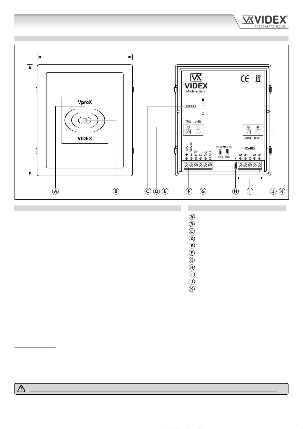
ART. 4850R PROXIMITY READER MODULE
103mm
4850R
120mm
Fig. 17
DESCRIPTION LEGEND
The Art.4850R proximity reader is an expansion reader that can be connected to
the Art.4810 GSM PRO intercom via an RS485 bus connection. It allows the GSM
intercom to have up to 7 additional proximity access doors or can be used with
a combination of proximity and coded access using the Art.4903 keypad (up to
a total of 8 devices with the GSM PRO’s onboard reader as device ID.1).
The front of the module has a tri-colour LED to indicate to the user the status of
the reader (amber = standby, green = access granted and red = access denied).
The reader is housed in a 4000 series module with a stainless steel or aluminium
surround front frame, see Fig.17.
When connected directly to the GSM PRO intercom module with the RS485 bus
connection it can be programmed by either sending SMS text messages (refer
to notes programming the GSM intercom on pages 38 - 62) or using the GSMSK
PC software (refer to the manual: GSMSK_66251720_EN_V2-0 or later).
Proximity reading area
Status indication LED
Current rmware version (FW X.X)
Programming indication LED's (yellow)
Tens and Units programming buttons
Power input terminals
PTE input & relay (C/NC/NO) terminals
RS485 bus termination jumper
RS485 bus terminals
Store and Delete programming buttons
Store LED (green) and Delete LED (red)
STEEL
ALI
HIGH BRASS
MATTE
It has a single onboard relay with common (C), normally open (NO) and normally closed (NC) connections and a switched 0V push
to exit input (PTE) to enable the activation of the relay. The relay operating time can be set for 01 - 99 seconds or 00 for latching
and can be programmed by using a combination of the tens, units and store buttons on the back of the module (also refer to
programming the relay time on page 19). Presenting a programmed fob will activate the relay for the programmed relay time.
The unit ID (1 - 8) can be set by using a combination of the units, store and delete buttons on the back of the module (also refer to
setting the unit ID on page 19).
IMPORTANT NOTE: The Art.4850R reader can only be used as an expansion reader for the GSM PRO intercom, therefore
programming can only be carried out (when connected by RS485) by sending SMS text messages to the GSM PRO or using the
GSMSK PC software (software version 4.0.0.0 or later). The only manual programming that can be performed on the module is
the unit ID setup and relay time. All proximity fob data is actually stored in the GSM module’s memory and not the proximity
reader.
Compatible key fobs: 955/T and/or PBX-1E ; compatible proximity cards: 955/C and/or PBX-2.
IMPORTANT NOTE: MIFARE PROXIMITY FOBS/CARDS CANNOT BE USED WITH THIS READER.
4000 Series GSM Audio Intercom - Technical Manual
- 18 -
66250754-EN - V1.1 - 27/06/19
Page 19
4000 Series GSM Audio Intercom with Proximity
Art. 4850R Technical Information
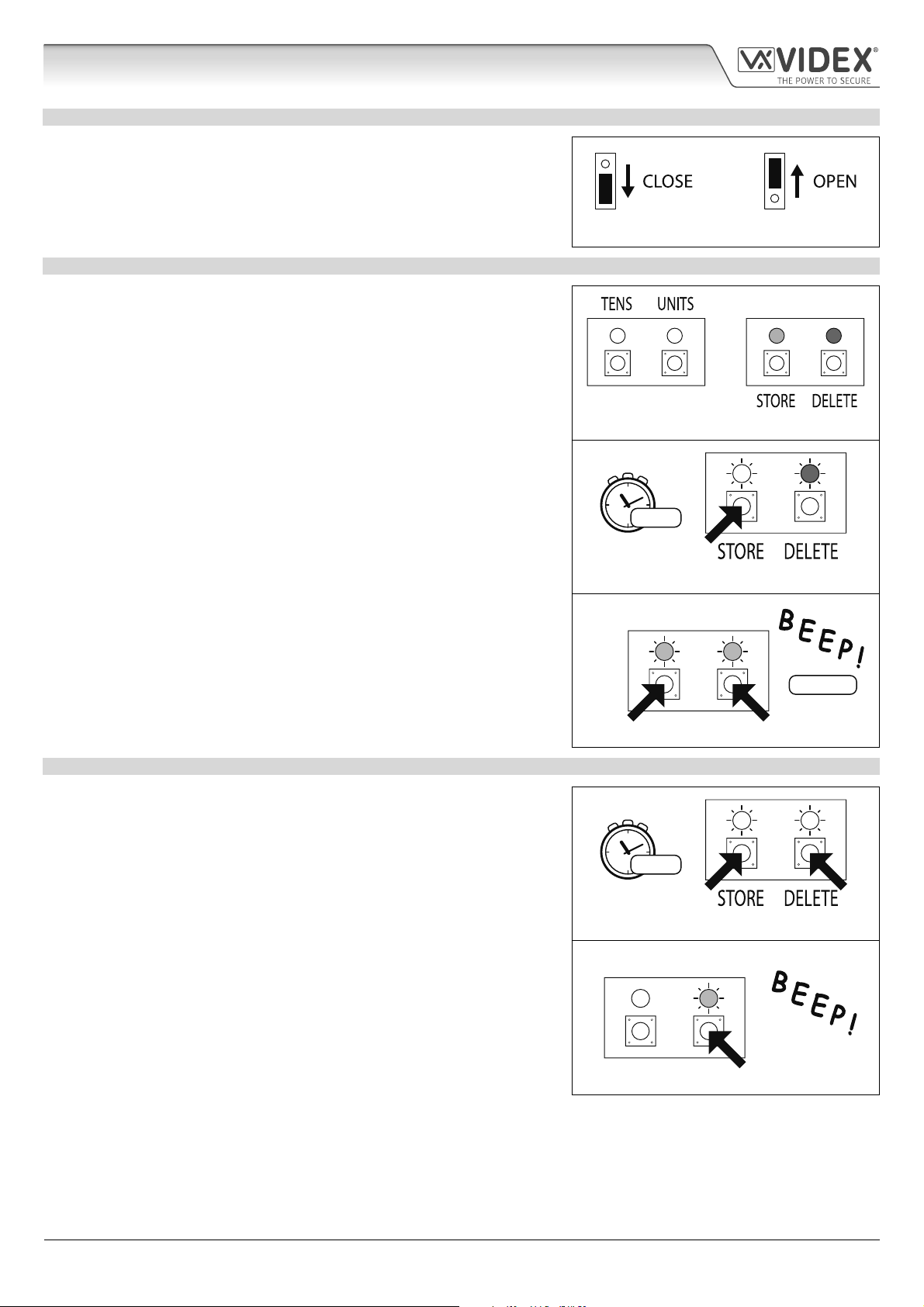
RS485 BUS TERMINATION JUMPER
The jumper on the rear of the proximity reader sets the RS485 bus termination
when connected to the Art.4810 GSM PRO or other RS485 devices. By default
the jumper is set to the closed position (lower two pins). When more than one
RS485 device is connected to the reader in line on the RS485 bus terminals then
the jumper can be set to the open position (upper two pins) and only set to the
closed position on the end of line device, see Fig.18.
PROGRAMMING THE RELAY TIME 00, 01 99
In standby the green store LED and red delete LED on the back of the module
will be ON, the yellow tens and units LED’s will be OFF, see Fig.19. Follow the
steps below to set the relay time:
1. Press and hold down the store button for approximately 6 seconds until the
green store LED switches OFF and the red delete LED stays ON, see Fig.20;
2. Use the tens and units buttons to set the relay time, e.g. to set the relay time
to 25 press the tens buttons twice and the units button 5 times (listen for the
conrmation beep each time the button is pressed and observe the yellow
tens/units LED’s as they should ash each time that each button is pressed),
see Fig.21;
Fig. 18
Fig. 19
3. Press the store button once to conrm the setting (again listen for the
conrmation beep when the button is pressed and observe the green store
LED as this should ash once);
4. Both the green store LED and red delete LED will switch back ON and put the
reader back into standby;
5. The reader is ready to be programmed.
To set the relay time for latching press and hold down the store button (follow
step 1 above). Once the red delete LED stays ON and the green store LED is OFF,
press the store button once to conrm (follow step 3 above). The relay time will
be set for 00 seconds.
SETTING THE UNIT ID 1 8
In standby the green store LED and red delete LED on the back of the module
will be ON, the yellow tens and units LED’s will be OFF, see Fig.19. Follow the
steps below to set the unit ID:
1. Press and hold down both the store and delete buttons for approximately 6
seconds until both the green and red LED’s switch OFF, see Fig.22;
2. Use the units button to set the unit ID of the reader, e.g. to set the unit ID to
5 press the units button 5 times (listen for the conrmation beep each time
the button is pressed and observe the yellow units LED as this should ash
each time the button is pressed), see Fig.23;
3. Press the store button once to conrm the setting (again listen for the
conrmation beep when the button is pressed and observe the green store
LED as this should ash once);
4. Both the green store LED and red delete LED will switch back ON and put the
reader back into standby;
5. The reader is ready to be programmed.
6 secs...
Fig. 20
TENS UNITS
set 25 secs.
5x units2x tens
Fig. 21
6 secs...
Fig. 22
TENS UNITS
Fig. 23
4000 Series GSM Audio Intercom - Technical Manual
- 19 -
66250754-EN - V1.1 - 27/06/19
Page 20
4000 Series GSM Audio Intercom with Proximity
Art. 4850R Technical Information
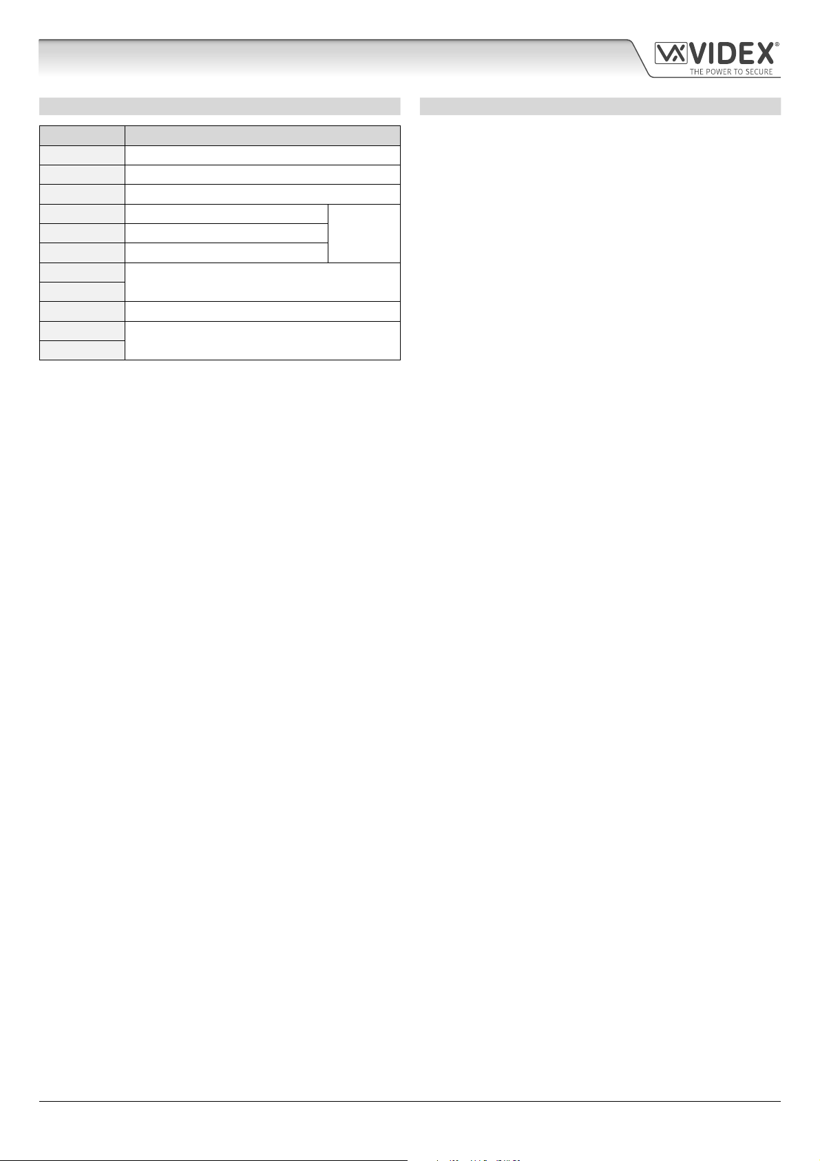
TERMINAL CONNECTIONS TECHNICAL SPECIFICATION
Connection Description Working voltage: 12V - 24Vac/dc +/- 10%
+ 12-24V AC or DC power input Current (standbay): 150mA
- 0V power input Current (operation): 150mA (max.)
PTE Switched 0V input to trigger relay Number of relays: 1x, C, NC and NO
C Relay common connection
NC Relay normally closed connection Push to exit inputs: 1x, PTE (switched 0V)
NO Relay normally open connection RS485 bus connections: 2x A, 2x B and - (GND)
B
A Networkable: via RS485 (up to 8 devices max.)
RS485 bus terminal connections
3A @
24Vac⁄dc
max.
- RS485 ground connection Programming: Tens, units, store & delete buttons
B
A SMS text message (via RS485);
RS485 bus terminal connections
Relay current⁄voltage: 3A @ 24Vac/dc (max.)
RS485 termination: Yes, Jumper
(for unit ID & relay time only);
GSMSK PC software (via RS485)
Working Temperature: -10 +50
o
C
4000 Series GSM Audio Intercom - Technical Manual
- 20 -
66250754-EN - V1.1 - 27/06/19
Page 21
4000 Series GSM Audio Intercom with Proximity
Wiring Diagrams
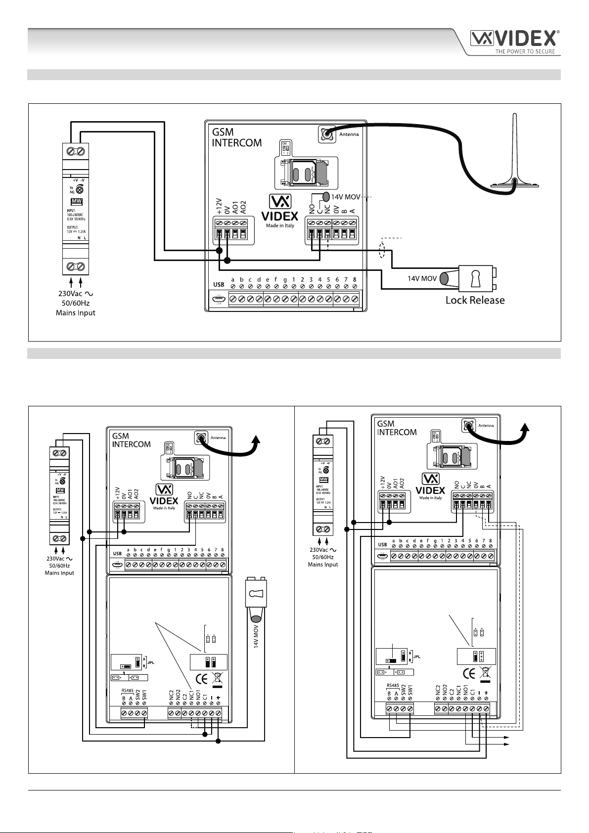
GSM4K CONNECTIONS
Fig.24 shows the wiring connections for a GSM4K-1/GSM4K-1S audio kit.
For fail secure locks a
MOV must also be tted
across terminals C & NO and
for fail safe locks across C & NC.
For fail safe lock wiring move
lock wire from NO to NC.
Fig. 24
GSM4KCR CONNECTIONS
Fig.25 shows the wiring connections for a GSM4KCR-1/GSM4KCR-1S audio kit when the Art.4903 is used as a standalone keypad.
Fig.26 shows connections for a GSM4KCR-1/GSM4KCR-1S audio kit when the additional access code features of the GSM PRO
module are required when connecting it with the RS485 bus terminals to the Art.4903 keypad.
To Antenna
To Antenna
Art.4810
Art.4810
Fail Secure
Art.4903
For fail safe lock wiring move lock
wire from NO1 to NC1 and move
JP2 jumper to the NC1 position
OFFON
RS485 BUS TERMINATION
MOV
Lock Release
NO1 NC1
NO2 NC2
Art.4903
For volt free contacts to gate
controls remove JP2 jumper
RS485 bus termination
jumper in OFF position
OFFON
RS485 BUS TERMINATION
MOV
NO1 NC1
NO2 NC2
RS485 bus cable
Fig. 25 Fig. 26
4000 Series GSM Audio Intercom - Technical Manual
- 21 -
(2 core twisted or CAT-5 where: 1 core = A, 1 core = B, 1 pair = 0V/GND)
Volt Free
Contacts
66250754-EN - V1.1 - 27/06/19
Page 22
4000 Series GSM Audio Intercom with Proximity
Wiring Diagrams
CONNECTING TO A GATE CONTROLLER
For a GSM4K series audio kit if the Art.4810 GSM intercom is going to be connected to an electric gate then the wires from the gate
controls can be connected directly into the C and NO relay terminals on the GSM module, as shown in Fig.27. For a GSM4KCR series
audio kit if the gate controls are going to be connected directly to the Art.4903 keypad the relay terminals C1 and NO1 can be used
(or C2/NO2 depending on the relay required), remembering to remove the respective back EMF protection jumper (JP2 or JP3), as
shown in Fig.28.
To
Art.4903
Antenna
Art.4810
0V (GND)
+12Vdc
Volt Free connections
to gate controls
Art.4903
When using relay 1 connections C1/NO1
to gate controls remove JP2 jumper (if
using relay 2 [CO2/NO2] remove JP3
jumper)
MOV
NO2 NC2
RS485 BUS TERMINATION
OFFON
NO1 NC1
+12Vdc
0V (GND)
Volt Free connections
to gate controls
Fig. 27 Fig. 28
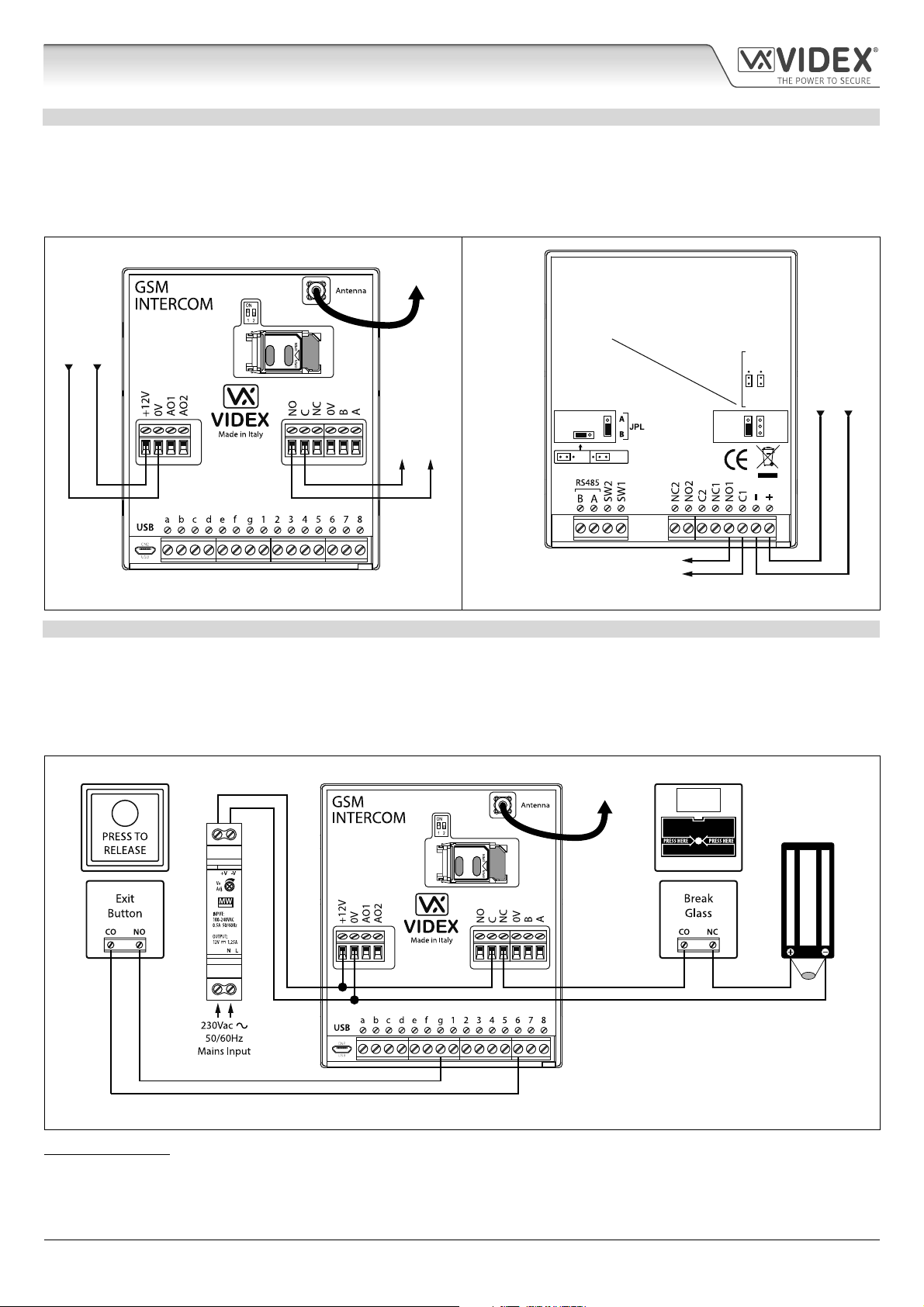
CONNECTING A PUSH TO EXIT BUTTON AND A BREAK GLASS UNIT
The push to exit button must be congured as a “push-to-make” switch and connected across terminals g & 6 on the Art.4810 GSM
PRO module. The break glass unit, congured as a “push-to-break”, would only be used when connecting a fail safe/fail open lock
release (e.g. a mag lock) and would connect in series with the GSM’s relay connections C and NC, as shown in Fig.29.
When the exit button is pressed the GSM relay will trigger for the programmed relay time. When the break glass unit is activated it
will break the power to the mag lock.
To
Antenna
Art.4810
EMERGENCY
DOOR RELEASE
Emergency Break Glass
12Vdc
MAG LOCK
14-20V
MOV
Fig. 29
IMPORTANT NOTE: In instances where the current draw of the lock (fail secure or fail safe) exceeds the current rating of the
HDR15-12 (1.25A) power supply a separate power supply with a sucient current rating will be required to power the lock.
4000 Series GSM Audio Intercom - Technical Manual
- 22 -
66250754-EN - V1.1 - 27/06/19
Page 23
4000 Series GSM Audio Intercom with Proximity
Auxiliary Inputs/Outputs
AUXILIARY OUTPUT AO1
The auxiliary output AO1 has six modes 00 - 05 and is set using the A1M command (refer to page 44 for full list of A1M programming
modes). It is an open collector output (switched low, 150mA max.) and depending on the mode it is set to will determine how the
AO1 output behaves. The following examples show how the AO1 output can be connected.
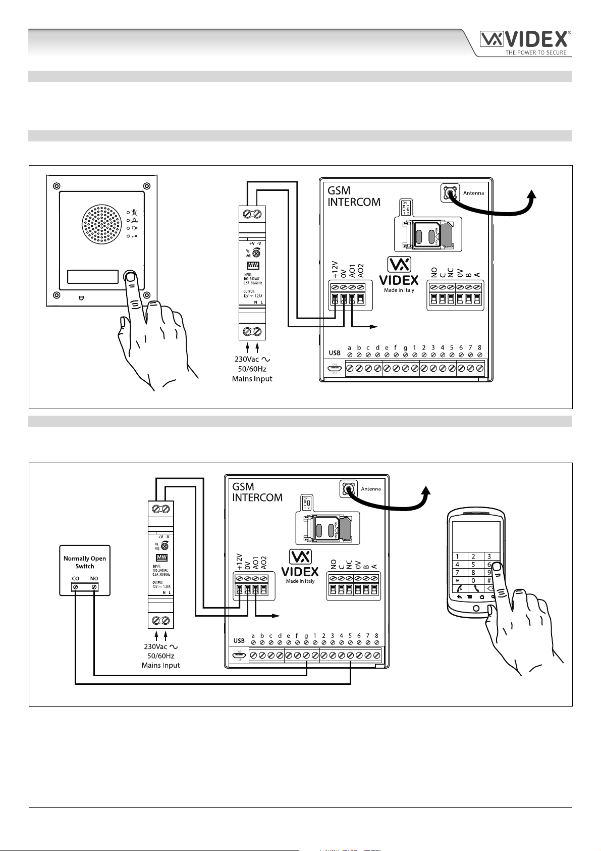
AO1 SET TO MODE 00, ‘CALL ACTIVATED’
When set to mode 00 auxiliary output AO1 will activate when the call begins and deactivate when the call ends, as shown in Fig.30.
To Antenna
Art.4810
AO1 output will activate
for the duration of the call
Fig. 30
AO1 SET TO MODE 01, ‘USER ACTIVATED’
When set to mode 01 auxiliary output AO1 will activate when the terminals g & 5 are shorted together on the GSM PRO module or
by pressing 6 on the telephone during a call, as shown in Fig.31. Auxiliary output AO1 will only activate for the programmed time.
To Antenna
Art.4810
OR
AO1 output will activate
for the programmed time
Fig. 31
4000 Series GSM Audio Intercom - Technical Manual
- 23 -
66250754-EN - V1.1 - 27/06/19
Page 24
4000 Series GSM Audio Intercom with Proximity
Auxiliary Inputs/Outputs
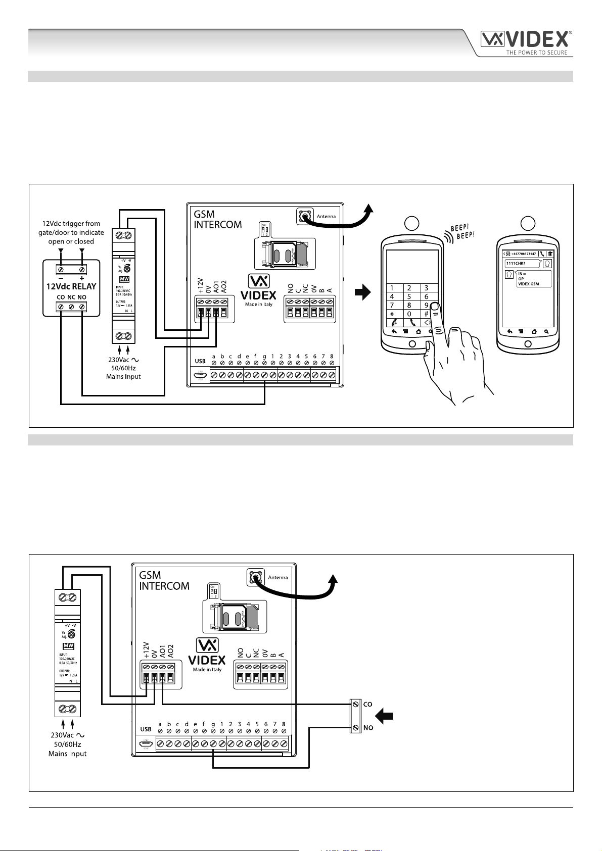
AO1 SET TO MODE 02, ‘STATUS INDICATION’
When set to mode 02 auxiliary output AO1 is used exclusively as a monitoring input. For example, checking if a gate/door is open
or closed. Once set the AO1 input status can be interrorgated in two ways:
1. During a call: press 9 on the telephone keypad and listen to the number of beeps in the ear piece. One beep indicates the input
is closed and two beeps indicates the input is open.
2. At anytime: send the SMS message 1111CHK? to the GSM PRO intercom. An SMS message will be returned with IN=OP for
open or with IN=CL for closed.
For this feature an additional relay will be required and the AO1 input must be wired as shown in Fig.32.
To Antenna
1 2
Art.4810
OR
Fig. 32
AO1 SET TO MODE 03, ‘DIVERT CALLS TO MASTER NUMBER’
It is possible to have the GSM PRO call buttons diverted to the master number (outside certain hours) using the TBA timeband
feature (refer to timeband TBA programming notes on page 48). Alternatively it is possible to divert the GSM PRO call buttons to
the master number when auxiliary output AO1 has been set to mode 03 (auxiliary output AO1 is used as a monitoring input). In
this instance a switched common and normally open (CO/NO) trigger needs to be used to enable or disable ‘divert calls to master
number’ and the auxiliary output AO1 must be wired as shown in Fig.33. In either case a master number is required following the
STM store master number feature (refer to STM programming notes on page 47).
If there is no master number stored, the intercom will beep and the busy LED will ash once to indicate no call is taking place (if the
speech board is switched ON, the GSM PRO module will announce “the phone is switched o please try later”).
To Antenna
Art.4810
Normally open (NO) switched input to
enable and disable divert to master number
Fig. 33
4000 Series GSM Audio Intercom - Technical Manual
- 24 -
66250754-EN - V1.1 - 27/06/19
Page 25

4000 Series GSM Audio Intercom with Proximity
Auxiliary Inputs/Outputs
AO1 SET TO MODE 04, ‘CALL ACTIVATED TIMED’
Similar to mode 00, however, when set to mode 04 auxiliary output AO1 will activate when the call begins and deactivate when the
auxiliary AO1 time expires, see Fig.34.
The auxiliary output AO1 time can be set using the SMS programming code 1111A1Tnn? (where nn = time in seconds, also refer to
notes programming the GSM intercom on pages 38 - 62) or setup by using the GSMSK PC programming software.
To Antenna
Art.4810
AO1 output will activate
for the programmed time
Fig. 34
AO1 SET TO MODE 05, ‘ENABLE/DISABLE DIAL TO OPEN NUMBERS’
When the auxiliary output AO1 mode is set to 05 the dial to open numbers will only activate the GSM relay when a common and
normally open (CO/NO) switch connected across terminals g & AO1, as shown in Fig.35, is open circuit. When the switch is closed
and terminals g & AO1 are short together this will disable the dial to open numbers.
To Antenna
Art.4810
Normally open (NO) switched input to
activate and deactivate dial to open numbers
Fig. 35
IMPORTANT NOTE: When auxiliary output AO1 is set to a particular mode (00 - 05) it cannot be used as an input/output for
anything else.
4000 Series GSM Audio Intercom - Technical Manual
- 25 -
66250754-EN - V1.1 - 27/06/19
Page 26

4000 Series GSM Audio Intercom with Proximity
Auxiliary Inputs/Outputs
AUXILIARY OUTPUT AO2
The auxiliary output AO2 is an open collector output (switched low, 150mA max.) and can be used to switch a negative trigger onto
a transistor switched device, for example an Art.506N, for the programmed A2T time (refer to notes on page 45 setting the A2T
time). This can be particularly useful when switching an additional device for instance a secondary gate control.
The AO2 output can only be triggered in two ways:
1. During a call: press 5 on the telephone keypad to activate AO2 for the programmed A2T time.
2. At anytime (depending on the operation required) send one of the following SMS messages to the GSM intercom: 1111A2O?
to trigger the AO2 output for the programmed A2T time. 1111A2L? to latch the AO2 output. 1111A2U? to unlatch the AO2
output.
For this feature an additional transistor switched device will be required. Fig.36 below shows an example of connecting an Art.506N
relay to the AO2 output.
To Antenna
Art.4810
Fig. 36
AUXILIARY INPUT 2
Auxiliary input 2 connects across terminals g & 4 on the GSM PRO module. When this input is triggered it will send an SMS message
to the master telephone number, as shown in Fig.37, (to store a master number STM follow the SMS programming section on page
47 or the relevant steps in the GSMSK_66251720_EN_V2-0 software manual). Once this input is triggered it cannot be triggered
again for 4 minutes, this is to avoid multiple SMS messages being sent for the same alarm.
To Antenna
Art.4810
Fig. 37
IMPORTANT NOTE: auxiliary input 2 has been specically setup for this function and does not activate auxiliary output AO2.
Refer to the notes at the top of this page for activating auxiliary output AO2.
4000 Series GSM Audio Intercom - Technical Manual
- 26 -
66250754-EN - V1.1 - 27/06/19
Page 27

4000 Series GSM Audio Intercom with Proximity
USB & RS485 Connection to a PC
CONNECTIONS TO A PC
The GSM PRO module includes two options for connecting to a PC: via a USB connection or via an RS485 connection. Both methods
of connection are to allow for ease of programming and monitoring using the GSMSK PC software.
IMPORTANT: WHEN A USB CONNECTION IS PLUGGED INTO THE GSM PRO THE RS485 CONNECTION IS DISABLED.
All programming features described in this manual are also accessible using the software. Further information on using the GSMSK
PC software can be found in the technical manual GSMSK_66251720_EN_V2-0 (or later version).
OPTION 1: USB CONNECTION
The GSM PRO module can be connected using a standard micro-USB to USB cable as shown in Fig.38. This method of connection
is primarily used for programming and setup of the GSM module only.
To Antenna
PC
Art.4810
IMPORTANT NOTE:
The USB input is not intended for a
permanent connection to the PC and
should only be used for programming.
For a permanent connection refer to
OPTION 2, RS485 notes below.
micro-USB to USB cable
Fig. 38
OPTION 2: RS485 CONNECTION
The GSM PRO module can also be connected using an RS485 bus connection via an RS485 to USB converter (Art.481) as shown
in Fig.39. This method of connection, like option 1, can be used for programming and setup of the GSM module, but can also be
used in instances where a permanent connection to a PC is required for monitoring purposes and downloading event logs. When
connected in this way the GSM module can only be connected as a ‘one-to-one’ bus connection to the PC, another GSM PRO
module cannot be connected on the same RS485 bus to the PC.
To Antenna
Art.4810
switch to RS485 position
RS-232
485 / 232
Art. 481
USB-Serial Converter
RS-485
BUS
Termination
ABGND
Open
Close
USB-PC
BUS
termination
jumper in
the closed
position
PC
RS485 cable
USB cable
Fig. 39
*For end of line termination a 120Ω resistor must be tted across the RS485 terminals A and B, as shown in Fig.39, but only if the
GSM PRO intercom is the last device in line and over a great distance (500m max.). Over shorter distances the 120Ω resistor is not
required and the bus termination jumper on the Art.481 can be set to the OPEN position.
4000 Series GSM Audio Intercom - Technical Manual
- 27 -
66250754-EN - V1.1 - 27/06/19
Page 28

4000 Series GSM Audio Intercom with Proximity
RS485 Network Connection
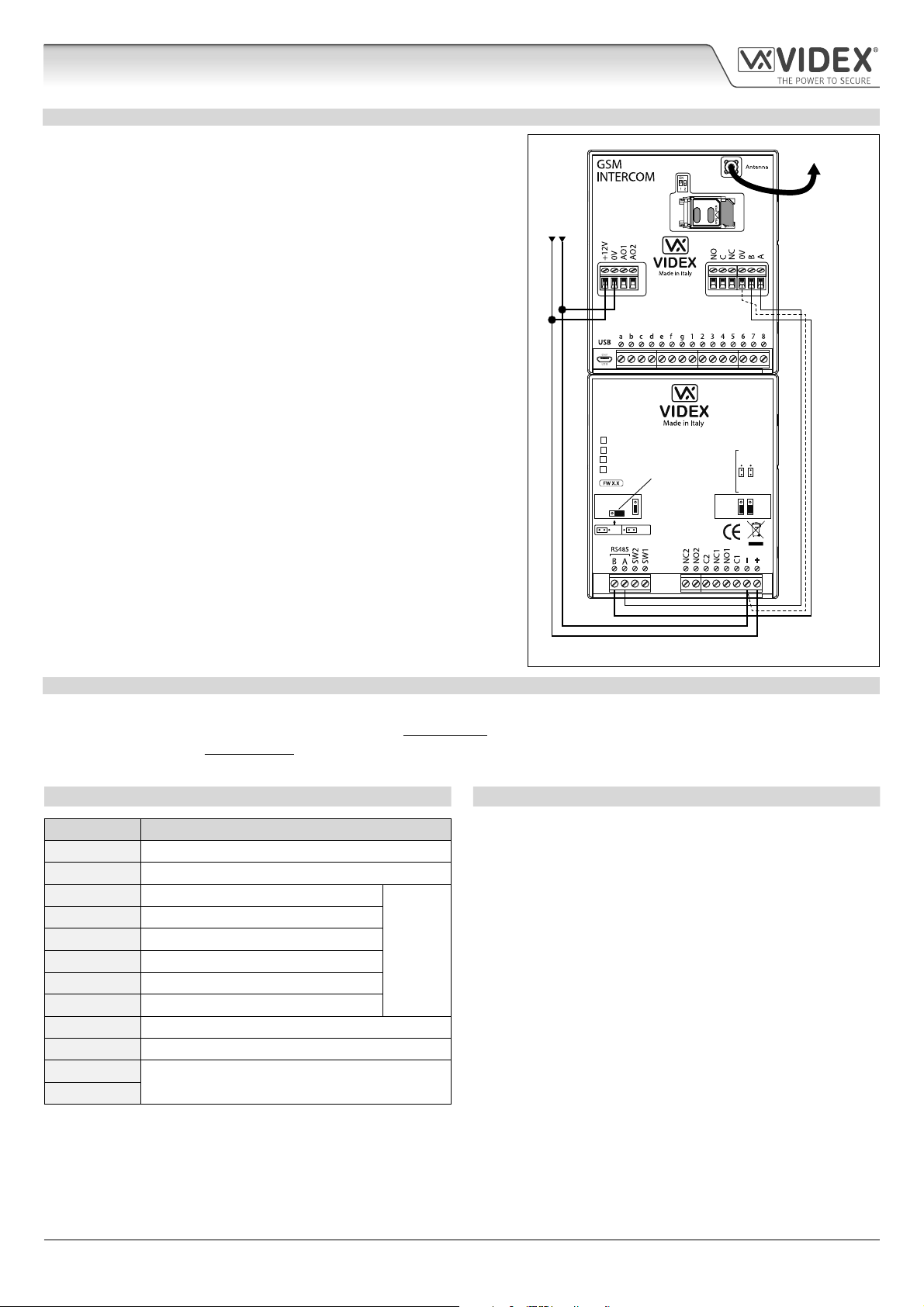
ART. 4903 NETWORK CONNECTION USING RS485
As mentioned previously, refer to Fig.16 on page 17, the Art.4903 keypad can be connected via the RS485 bus terminals to the
Art.4810 GSM PRO module allowing additional features of the GSM PRO to become available, which include:
• the capacity to store up to 400 permanent access codes (000 - 399);
• assign any of the 400 access codes to an access level (0 - 9);
• the capacity to store up to 32 temporary access codes;
• allocate any of the 32 temporary codes to a specic time period (between 1 - 255 hours) after which time the code will be
deleted;
• assign any of the access codes, whether permanent or temporary, to trigger either of or both of the relays (RLY1 and/or
RLY2).
Not only does the RS485 connection allow the Art.4903 keypad to be connected to the GSM PRO intercom, but also allows it to be
networked with other Art.4903 keypads up to a total of 8 devices with each device setup with a unit ID (1 - 8). This feature also means
that the networked keypads can have a permanent connection to a PC with the inclusion of an Art.481 (RS485 to USB converter),
see Fig.41 on page 29, the advantage of which is that the keypads can be programmed directly using the GSMSK PC software and
if required monitored for events (refer to technical manual: GSMSK_66251720_EN_V2-0 or later for more information).
ART. 4850R NETWORK CONNECTION USING RS485
Like the Art.4903 keypad the Art.4850R expansion reader can also be connected to the GSM PRO intercom via the RS485 terminals
(up to a total of 8 devices, 7 readers with the GSM PRO’s onboard reader as device ID.1) and each setup with a unit ID (1 - 8). As
before this feature allows the additional proximity readers to be permanently connected to a PC with the inclusion of an Art.481
(RS485 to USB converter), see Fig.42 on page 30.
The proximity readers operate as expansion readers only so the maximum capacity of proximity fobs/cards stored on the GSM PRO
intercom is still only 1000 (000 - 999) fobs/cards.
IMPORTANT NOTE: Both the Art.4903 keypad and the Art.4850R proximity reader can be networked together with the GSM
PRO provided that the overall number of devices on the RS485 bus does not exceed a total of 8 devices (excluding the Art.481
converter). All devices on the RS485 bus must have a unique unit ID setup including the GSM PRO intercom, see Fig.40 below.
It should also be noted that programming of the additional features for both the keypad and expansion reader can also be carried
out by sending SMS text messages to the GSM PRO intercom (refer to the notes programming the GSM intercom on pages 38 - 62).
Fig. 40
Art.4810
Art.4903
Art.4903
RS485 bus
termination
jumper in
OFF position
RS485 BUS TERMINATION
UNIT ID.1
UNIT ID.2
OFFON
To Antenna
switch to RS485 position
RS-232
485 / 232
Art. 481
USB-Serial Converter
RS-485
BUS
Termination
ABGND
Open
Close
USB-PC
RS485 bus
termination
jumper in
CLOSED position
USB cable
For more information on
MOV
cable requirements refer to
NO2 NC2
notes: general directions
NO1 NC1
for installation on page 31
(2 core twisted or CAT-5 where: 1 core = A, 1 core = B, 1 pair = 0V/GND)
RS485 bus cable
Art.4850R
UNIT ID.3
RS485 bus
termination
jumper in OPEN
position (set to
CLOSED position
when end of line)
Networked Art.4850R readers and Art.4903 keypads
RS485 bus wires and common GND wire.
(UNIT ID’s 4, 5, 6, 7 and 8)
4000 Series GSM Audio Intercom - Technical Manual
- 28 -
66250754-EN - V1.1 - 27/06/19
Page 29

4000 Series GSM Audio Intercom with Proximity
RS485 Network Connection
Art.4810
Art.4903
RS485 bus
termination
jumper in
OFF position
RS485 BUS TERMINATION
UNIT ID.1
OFFON
To Antenna
switch to RS485 position
RS-232
485 / 232
Art. 481
USB-Serial Converter
RS-485
BUS
Termination
A B GND
Open
Close
USB-PC
RS485 bus
termination
jumper in
CLOSED position
USB cable
Art.4903
UNIT ID.2
RS485 bus
termination
MOV
NO1 NC1
NO2 NC2
jumper in
OFF position
RS485 BUS TERMINATION
MOV
NO1 NC1
NO2 NC2
OFFON
Volt Free Contacts RLY2
Volt Free Contacts RLY1
Volt Free Contacts RLY2
Volt Free Contacts RLY1
NOTES: Connecting to a PC using the Art.481 is optional and only required if
permanently connecting to a PC and can be used as an alternative means of
PC programming to using the USB connection. Remember the GSM PRO
module can be connected directly to the PC using the USB connection and
then an RS485 bus connection used to connect the other devices.
Art.4903
UNIT ID.8
RS485 bus
termination
jumper in
ON position
RS485 BUS TERMINATION
OFFON
MOV
NO2 NC2
NO1 NC1
Art.4903
RS485 bus
termination
jumper in
OFF position
RS485 BUS TERMINATION
RS485 bus wires and
common GND wire.
Networked Art.4903 keypads:
UNIT ID’s 3, 4, 5 and 6
UNIT ID.7
MOV
NO2 NC2
NO1 NC1
OFFON
Volt Free Contacts RLY2
Volt Free Contacts RLY1
Volt Free Contacts RLY2
Volt Free Contacts RLY1
Fig. 41
IMPORTANT NOTE: For each additional Art.4903 keypad a 12Vdc power supply (HDR-15-12) will be required.
4000 Series GSM Audio Intercom - Technical Manual
- 29 -
66250754-EN - V1.1 - 27/06/19
Page 30

4000 Series GSM Audio Intercom with Proximity
RS485 Network Connection
switch to RS485 position
USB cable
485 / 232
USB-PC
RS-232
Art. 481
USB-Serial Converter
RS-485
BUS
Termination
A B GND
Open
Close
RS485 bus
termination
jumper in
CLOSED position
UNIT ID.1
To Antenna
Art.4810
Volt Free
Contacts
Art.4850R
NOTES: Connecting to a PC using the Art.481 is optional and only required if
permanently connecting to a PC and can be used as an alternative means of
PC programming to using the USB connection. Remember the GSM PRO
module can be connected directly to the PC using the USB connection and
then an RS485 bus connection used to connect the other devices.
UNIT ID.2
RS485 bus
termination
jumper in
OPEN position
Volt Free Contacts
RS485 bus wires and
common GND wire.
Networked Art.4850R readers:
UNIT ID’s 3, 4, 5 and 6
Art.4850R
UNIT ID.8
RS485 bus
termination
jumper in
CLOSED position
Volt Free Contacts
Art.4850R
UNIT ID.7
RS485 bus
termination
jumper in
OPEN position
Volt Free Contacts
Fig. 42
IMPORTANT NOTE: For each additional Art.4850R proximity reader a 12Vdc power supply (HDR-15-12) will be required.
4000 Series GSM Audio Intercom - Technical Manual
- 30 -
66250754-EN - V1.1 - 27/06/19
Page 31

4000 Series GSM Audio Intercom with Proximity
General Directions for Installation
CABLE SIZE GUIDE
POWER SUPPLY AND LOCK RELEASE CONNECTIONS
Refer to the table below for the connections for the power supply output to the Art.4810 GSM PRO intercom and the lock release
connections.
Distance 20m 50m 100m
Cross Sectional Area (CSA) 0.5mm
2
Ideally the power supply should be located as close to the intercom panel as possible for best performance. The maximum
acceptable resistance for the above cables = 3Ω or less for best possible performance.
RS485 CONNECTIONS
A CAT-5 cable is acceptable where 1 pair is used for the 0V/GND connection and a second pair
is split between the A and B connections (i.e. 1 core of the pair is used for the A terminal, 1
core of the pair is used for the B terminal, see Fig.43).
The total overall distance between the rst RS485 device in line (Art.481 or GSM PRO module)
and the last RS485 device in line (Art.4903 or Art.4850R) should be no more than 500m max. for
the best possible performance, see Fig.44. It is also important that the end of line RS485 bus
termination of the respective device (Art.4903 or Art.4850R) is in the ON position, in the case
of the GSM PRO module a 120 Ohm resistor should be tted across the A and B bus terminal
connections (unless it’s connected with an Art.481, in which case the bus termination jumper
on the Art.481 should be in the closed position as this would be the last RS485 device in line).
1.0mm
2
1.5mm
2
CAT-5 cable
Fig. 43
First device
in line
RS-232
485 / 232
Art. 481
USB-Serial Converter
RS-485
BUS
Termination
A B GND
Open
Close
USB-PC
UNIT ID.1
Art. 4810-1
Art. 4903
UNIT ID.2
Art. 4850R
UNIT ID.3
Art. 4903
UNIT ID’s 4, 5, 6 and 7
Last device
in line
UNIT ID.8
Art. 4903
RS485 RS485 RS485RS485
CAT-5 cable 500m (max.)
Fig. 44
IMPORTANT NOTE: Only bare copper (BC) cable should be used (solid or stranded is acceptable). Please be aware that when
selecting a cable the following should NOT be used: Copper Coated Steel (CCS) and Copper Clad Aluminium (CCA). While these
types of cable may oer a low cost solution they will have a higher resistance than pure copper cable and can aect the overall
performance of the system therefore Videx DO NOT recommend these types of cable.
GENERAL INSTALLATION NOTES
• Check that all components are free from damage before installing (do not proceed with installation in the event of damage).
• Keep all packaging away from children (please dispose of any excess waste and packaging responsibly).
• Do not obstruct the ventilation openings or slots on any of the devices.
• All connections to mains voltages must be made to the current national standards (I.E.E. wiring regulations for the UK or the
appropriate standards of your country if installing overseas).
• Install an appropriate fused spur or isolation switch to isolate the mains.
• Isolate the mains before carrying out any maintenance work on the system.
• Avoid water ingress into the rear of the module, always seal the module frame after installation using a suitable silicon based
sealant.
• All intercom and access control cables must be routed separately from the mains (ideally in a separate cable tray or duct).
4000 Series GSM Audio Intercom - Technical Manual
- 31 -
66250754-EN - V1.1 - 27/06/19
Page 32

4000 Series GSM Audio Intercom with Proximity
General Directions for Installation
LOCK RELEASE WIRING AND BACK EMF PROTECTION
When tting an electric lock release back EMF protection will be required. If tting an AC lock release then a 100nF ceramic disc
capacitor should be tted across the terminals of the lock, shown in Fig.45. If tting a DC lock release (fail secure or fail safe) then
a 1N4002 diode should be tted across the terminals on the lock, shown in Fig.46.
+
100nF CAP
Fig. 45 Fig. 46
If a 100nF ceramic disc capacitor or a 1N4002 diode are not available then a 14 - 20V MOV (metal oxide varistor) can be tted across
the lock terminals instead (refer to Fig.45 above) and can be tted on both an AC and DC lock. Connection examples can also be
seen on the various wiring diagrams on pages 21 and 22.
CONNECTION TO MAINS, SAFETY AND GUIDANCE NOTES
IMPORTANT: PLEASE READ THESE INSTRUCTIONS CAREFULLY BEFORE COMMENCING WITH THE INSTALLATION.
IMPORTANT: IT IS RECOMMENDED THAT ANY CABLING AND VIDEX PRODUCTS BE INSTALLED BY A COMPETENT
AND QUALIFIED ELECTRICIAN, SECURITY INSTALLATION SPECIALIST OR COMMUNICATIONS ENGINEER.
1N4002 DIODE
-
• DO NOT install any Videx product in areas where the following may be present or occur:
• Excessive oil or a grease laden atmosphere.
• Corrosive or ammable gases, liquids or vapours.
• Possible obstructions which would prevent or hinder the access and/or removal of the Videx product.
MAINS CONNECTION
The system MUST be installed in accordance with the current I.E.E. regulations (in particular I.E.E. Wiring regulations BS7671 for the
UK), or the appropriate standards of your country if installing overseas, in particular Videx recommends:
• Connecting the system to the mains through an all-pole
circuit breaker (refer to Fig.47) which shall have contact
separation of at least 3mm in each pole and shall disconnect
all poles simultaneously.
• That the all-pole circuit breaker shall be placed in such a
way to allow for easy access and the switch shall remain
readily operable.
• Ensuring that the mains supply (Voltage, Frequency and
Phase) complies with the product rating label (this is usually
located on the topside of the power supply).
• Isolating the mains before carrying out any maintenance
work on the system.
1 PHASE
SUPPLY
(220 - 240Vac,
50/60Hz)
Fig. 47
N
FUSE
L
SWITCHED
FUSE SPUR
4000 Series GSM Audio Intercom - Technical Manual
- 32 -
66250754-EN - V1.1 - 27/06/19
Page 33

4000 Series GSM Audio Intercom with Proximity
General Directions for Installation
POWER SUPPLY INSTALLATION
Follow the steps below when tting the HDR-15-12 (12Vdc 1.25A) power supply.
• Fix the power supply to a DIN rail (following Fig.48, Fig.49 and Fig.50).
• Switch OFF the mains using the circuit breaker (mentioned previously) and then make the connections as required shown on
the various wiring diagrams throughout this manual.
• Check the connections and secure the wires into the terminals ensuring that the low voltage (signal) cables are routed separately
from the high voltage (mains) cables.
• If applicable replace the terminal covers and x them back into place using the relevant screws.
• When all connections are made restore the mains supply.
Fig. 48 Fig. 49 Fig. 50
PANEL CARE
The door panel’s facia is either mirror nish stainless steel or matt nish aluminium. It
is important that the facia is cleaned on regular occasions to prevent dirt build up and
tarnishing of the metal.
A clean and soft cloth can be used with moderate warm water or non-aggressive cleansers.
Additional care should be taken to follow the grain of the metalwork when polishing
panels with a matte nish and always only polish in one direction to avoid light scratching
of the plate, see Fig.51. Also try to avoid any polish build up around the panel’s buttons
which may prevent the buttons from operating correctly.
DO NOT USE ANY OF THE FOLLOWING:
• Abrasive liquids;
• Chlorine-based liquids;
• Metal cleaning products (including Sidol stainless steel cleaner as this can aect the
etching and/or engraving);
• Hydrochloride bleaches.
IMPORTANT NOTE: IT IS IMPORTANT TO REGULARLY MAINTAIN THE “UP KEEP” OF THE GSM PRO PANEL CLEANING
AND GENERAL MAINTENANCE ETC. ANY FAULT OR DAMAGE THAT MAY OCCUR TO THE GSM PRO PANEL DUE TO
THE LACK OF CLEANING AND MAINTENANCE IS NOT THE RESPONSIBILITY OF VIDEX.
Fig. 51
4000 Series GSM Audio Intercom - Technical Manual
- 33 -
66250754-EN - V1.1 - 27/06/19
Page 34

4000 Series GSM Audio Intercom with Proximity
Fitting the SIM & Connecting Power
FITTING THE SIM CARD AND CONNECTING THE POWER TO THE GSM INTERCOM
After connecting the power supply, antenna, lock output and any auxiliary devices as shown in this manual and before powering up,
a SIM card must be installed (the SIM must already be registered with the network provider). The SIM holder can be found on the back
of the module under the SMA antenna connection. A SIM card from most network providers can be used (remember a network 3 SIM
will only work with the 3G version of the GSM PRO intercom). Follow the steps below to insert the SIM card.
FITTING THE SIM
1. On the back of the Art.4810 GSM PRO module slide the
SIM holder to the left until it ‘clicks’, as shown in Fig.52.
2. The SIM holder is hinged and will open out to the left,
see Fig.53.
3. Place the SIM card into the holder (it will only t one way,
see Fig.54) and fold the holder back down, see Fig.55.
4. Slide the SIM holder back to the right until it ‘clicks’, see
Fig.56.
5. Once the SIM is in place connect the appropriate call
buttons following the button matrix diagram shown in
Fig.4 on page 7.
Fig. 52 Fig. 53
6. Connect the Art.432 GSM antenna and then connect the
Fig. 54 Fig. 55
12Vdc power supply but DO NOT power up the system
yet.
7. Follow the initialisation process described below.
Fig. 56
POWER UP INITIALISATION SEQUENCE
The Art.4810 GSM PRO module requires approximately 30 seconds to initialise properly. We
recommend NOT sending any SMS messages or pressing buttons during this time.
1. First check all the necessary connections have been made correctly, following the wiring
diagrams shown in this manual, and when ready power up the system.
2. The busy LED will start to ash continuously, as shown in Fig.57 (this will continue to ash
until the end of the initialisation process).
3. Two short beeps will be heard from the GSM module followed by a 15 second delay, as
shown Fig.58.
4. Next a single short beep will be heard (in the meantime the busy LED will continue to ash
while it registers with the chosen network), then after a further 15 second delay the busy
LED will stop ashing to indicate that the GSM module has registered with the network, as
shown in Fig.59.
Fig. 57
...delay 15 secs...
Fig. 58
5. The GSM PRO intercom is ready to be programmed.
4000 Series GSM Audio Intercom - Technical Manual
...delay 15 secs...
Fig. 59
34
66250754-EN - V1.1 - 27/06/19
Page 35

4000 Series GSM Audio Intercom with Proximity
Reset Procedure
RESETTING THE GSM MODULE TO FACTORY DEFAULTS
There are two ‘hard-wired’ reset options available. The rst will reset the master code only and the second will reset everything and
clear all the stored telephone numbers, proximity cards, access codes, timebands and all settings.
RESETTING THE MASTER CODE TO 1111 4x1
1. Power down the GSM PRO intercom module.
2. Put a short across terminals g & 7 on the back of the GSM
PRO module, as shown in Fig.60.
3. Power up the GSM PRO module, 2 beeps will be heard
followed by a brief delay and then a 3rd beep, as shown in
Fig.61.
4. After the 3rd beep remove the short, as shown in Fig.62.
5. The master code is now reset back to 1111 (4x1).
FULL SYSTEM RESET
1. Power down the GSM PRO intercom module.
2. Put a short across terminals g & 8 on the back of the GSM
PRO module, as shown in Fig.63.
3. Power up the GSM PRO module, 2 beeps will be heard
followed by a brief delay and then a further 2 beeps, as
shown in Fig.64.
Fig. 60
...delay...
Fig. 61
Fig. 62
Fig. 63
4. After the 4th beep remove the short, as shown in Fig.65.
5. All settings on the GSM PRO module are returned to
factory defaults.
4000 Series GSM Audio Intercom - Technical Manual
...delay...
Fig. 64
Fig. 65
35
66250754-EN - V1.1 - 27/06/19
Page 36

4000 Series GSM Audio Intercom with Proximity
4000 Series Back Box Installation
EXAMPLE: INSTALLING A 4000 SERIES FOUR MODULE BACK BOX
C
Fig. 66 Fig. 67 Fig. 68
Y
G
H
B
F
G
Fig. 69 Fig. 70 Fig. 71 Fig. 72
C
A
C
E
D
D
C
W
C
H
M
L
L
H
M
M
Fig. 73 Fig. 74 Fig. 75
Q
P
H
N
P O
N
N
Fig. 76 Fig. 77 Fig. 78 Fig. 79
Fig. 80 Fig. 81 Fig. 82 Fig. 83
4000 Series GSM Audio Intercom - Technical Manual
- 36 -
66250754-EN - V1.1 - 27/06/19
Page 37

4000 Series GSM Audio Intercom with Proximity
4000 Series Back Box Installation
INSTALLING A SURFACE MOUNT DOOR STATION
1. Place the surface box against the wall (165-170cm between the top of the box and the oor level as shown in Fig.66), mark the xing
A
holes
2. As shown on Fig.67, drill the xing holes A, insert the wall plugs B and feed the cables E through the surface box opening D,
x surface box C to the wall using the screws F;
3. Apply the
4. Before installation of the module support frame, hook the modules
in Fig.71, t the two anti-tampering locks W for each module (do the same for the second module support frame);
5. When you have more than one support frame, hook the support frame to the surface box starting from the left. For convenience we
will describe how to attach the left frame but the same procedure must be carried out for the right frame. As shown in Fig.72, hook the
module support frame
the pivots L (Fig.72) go inside the relevant hinge housing M as shown in Fig.73;
6. As shown on Fig.74, pull back the module support frame
7. As shown in Fig.75, open the module support frame
M
adjusting the settings (through openings O) and adjust trimmers;
8. Repeat the same steps described above for the second module support frame (or for the third if available);
9. When the system has been tested and is working correctly, move back the module support frames carefully, x them to the surface box
using the screwdriver provided
than is necessary.
INSTALLING A FLUSH MOUNTING DOOR STATION
for the wall plugs B and the hole for the cables E (Fig.67). Observe the orientation of the box with the hinge on the left;
In order to prevent water ingress we highly recommend using a silicon sealant between the wall and the back box
C
, ON THE LEFT, TOP AND RIGHT SIDES ONLY AND AROUND ALL HOLES D. DON’T USE SILICON SEALANT ON THE
BOTTOM SIDE OF THE BACK BOX (Fig.68);
Y
neoprene seal on top of each module G as shown in Fig.69;
G
to the support frame H as shown in Fig.70 then, as shown
H
(complete with modules) to the surface box C moving the frame as suggested from the pointers. Ensure that
H
while moving it slightly to the left as suggested by the pointers;
H
as suggested by the pointer, hook the hinge locks N to the hinge housings
, make the required connections using the screwdriver provided P (at blade end) and make the required adjustments by
P
(torx end) and the pin machine torx screws Q (Fig.76). Note: do not over tighten the screws more
When ush mounting and the number of modules is greater than 3, the required back boxes need to be linked together (before
embedding them into the wall) as shown on Fig.79, Fig.80 and Fig.81:
• Arrange the back boxes and remove knockouts to allow cables to be fed from one back box to the other;
• Hook the spacers to the rst back box then hook the second back box to obtain the result shown on Fig.81;
1. Protect the module support frame xing holes from dust then embed the back box into the wall (165-170cm between the top of
the box and the oor level as shown on the Fig.66) feeding the cables
E
(Fig.67) through a previously opened hole in the box.
Observe the direction of the box ensuring the hinge is on the left and take care that the box prole is in line with the nished
wall prole;
In order to prevent water ingress we highly recommend using a silicon sealant between the module support frame
H
and the back box C, ON THE LEFT, TOP AND RIGHT SIDES ONLY. DON’T USE SILICON SEALANT ON THE BOTTOM
SIDE OF THE MODULE SUPPORT FRAME (Fig.77);
2. Continue from step 4 of surface mounting instructions, but at step 7 hook the hinge locks N as shown on Fig.78.
Note: if additional holes are made in the surface box, oxidation problems may appear unless the unprotected metal is
coated with a protective paint.
NOTES
• The screwdriver’s blade has two sides, one at and one torx, to select one of them unplug the blade from the screwdriver body
and plug it into the required side.
• The example shows the use of only one back box bottom hole for wires, this is done to keep le drawings clear. Naturally the
installer can use the left hole or the right or both if required.
HOW TO REMOVE THE CARD NAME HOLDER
• To avoid damage to the module front plate, tape the side that will be in contact with the screwdriver blade;
• lnsert the screwdriver (at side) into the card-holder hole as shown in Fig.82;
• Move the screwdriver to the left as shown in Fig.83 to extract the card name holder;
• Edit the card name then replace it inside the holder and ret: insert the holder inside its housing from the left or right side then
push the other side until it clips into place.
4000 Series GSM Audio Intercom - Technical Manual
- 37 -
66250754-EN - V1.1 - 27/06/19
Page 38

4000 Series GSM Audio Intercom with Proximity
Programming the GSM Intercom
PROGRAMMING THE GSM INTERCOM
Programming the GSM PRO intercom can be carried out in two ways, either by sending text (SMS) messages or by using the GSMSK
PC software (ver 4.0.0.0 or later), also refer to the programming manual GSMSK_66251720_EN_V2-0 (or later).
IMPORTANT NOTE: When you are required to use “ in a text message it is very important to use the correct symbol and not for
example ‘ (or two ‘ single apostrophes side by side which you will see look the same but will be interpreted dierently by the
GSM PRO intercom panel).
PROGRAMMING BY TEXT MESSAGE
Programming by text message is a simple way to customise the settings of the GSM PRO intercom panel and add or delete telephone
numbers. If you have a large number of buttons or telephone numbers to enter you may nd programming easier with the GSMSK
PC software. Simply send texts in the following format shown below to the telephone number of the SIM within the GSM PRO
intercom panel:
<4 DIGIT CODE> <3 DIGIT FUNCTION CODE> <OPTIONAL DATA> <OPTIONAL ?>
4 DIGIT CODE
3 DIGIT FUNCTION CODE
DESCRIPTION CODE EXAMPLE SETTINGS DEFAULT PAGE
Store a primary telephone no. STN 1111STNnnn”01912243174” nnn = 001 - 050 n/a 40 - 41
Store divert 1 telephone no. STD 1111STDnnn”01912241559” nnn = 001 - 050 n/a 40 - 41
Store divert 2 telephone no. STE 1111STEnnn”01912243678” nnn = 001 - 050 n/a 40 - 41
Store divert 3 telephone no. STF 1111STFnnn”01912245326” nnn = 001 - 050 n/a 40 - 41
Store a primary telephone no.
and divert no’s in a single text
message
Store a dial to open no. (DTO)
or
Store up to 5 dial to open no’s
(DTO) in a single text message to
the next available locations
Delete a dial to open no. without
knowing it’s location
Set call time SPT 1111SPTnn nn = 01 - 12 02 (40s) 43 - 44
Set relay time RLT 1111RLTnn nn = 00 - 99 05 (5s) 44
Set auxiliary AO1 output time A1T 1111A1Tnn nn = 00 - 99 05 (5s) 44
Set auxiliary AO1 out mode A1M 1111A1Mnn nn = 00 - 05 01 44
Set auxiliary AO2 output time A2T 1111A2Tnn nn = 00 - 99 05 (5s) 45
Keep connection facility NOD 1111NODnn nn = 01 - 99 0 (disabled) 45
Divert to next no. time DIT 1111DITnn nn = 01 - 99 15 (15s) 45
Check GSM signal strength SIG 1111SIG? n/a n/a 45
Check software version VER 1111VER? n/a n/a 45
Dial a number DLE 1111DLE”123” n/a n/a 45 - 46
Store SMS message for g-4 SMS 1111SMS”HouseAlarm” n/a AUX TRIG 46
Change 4 digit code CDE 1111CDE1234 Any 4 digits 1111 46
Trigger the relay RLY 1111RLY n/a n/a 46
Trigger the auxiliary output AO1 A1O 1111A1O n/a n/a 46
Trigger the auxiliary output AO2 A2O 1111A2O n/a n/a 46
Store balance check dial string SDL 1111SDL”*#1345#” n/a n/a 46
Check credit balance BAL 1111BAL? n/a n/a 46 - 47
This code prevents unauthorised access to the programmable features of the system. The code must
be four digits long but can be any combination using digits 0 – 9. The default code is 1111 and will
be used for all examples in this manual.
The 3 digit function code identies the programmable feature to be changed. The code must be in
capital letters. The following table lists the available codes.
STN 1111STNnnn”pn”,”d1”,”d2”,”d3”
1111STNnnn”01912243174”,
”01912241559”,” 01912243678”,
”01912245326”
STR 1111STRnnn”07771234567”
1111STR”n1”,”n2”,”n3”,”n4”,”n5”
1111STR”01912243174”,
”01912241559”,” 01912243678”,
”01912245326”,”07897123456”
DET 1111DET”01912243174” n/a n/a 43
nnn = 001 - 050
pn = primary no.
d1 = divert 1 no.
d2 = divert 2 no.
d3 = divert 3 no.
nnn = 000 - 999 or
nnn = optional
n1 = 1st DTO
n2 = 2nd DTO
n3 = 3rd DTO
n4 = 4th DTO
n5 = 5th DTO
n/a 41
n/a 42 - 43
4000 Series GSM Audio Intercom - Technical Manual
- 38 -
66250754-EN - V1.1 - 27/06/19
Page 39

4000 Series GSM Audio Intercom with Proximity
Programming the GSM Intercom
Store master telephone no. STM 1111STM”07771234567” n/a n/a 47
Latch the relay RLA 1111RLA n/a n/a 47
Unlatch the relay RUL 1111RUL n/a n/a 47
Latch the auxiliary AO1 output A1L 1111A1L n/a n/a 47
Unlatch the auxiliary AO1 output A1U 1111A1U n/a n/a 47
Latch the auxiliary AO2 output A2L 1111A2L n/a n/a 47
Unlatch the auxiliary AO2 output A2U 1111A2U n/a n/a 48
Store timeband for call buttons
to be active for
Store timeband(s) for access
control: proximity, access codes
and dial to open numbers to be
active for
Store access levels for access
control: proximity, access codes
and dial to open numbers to be
active for
TBA 1111TBA”HHMMHHMM”,days HHMMHHMM
days = Mo, Tu, We,
Th, Fr, Sa, Su, AD,
WD and WE
AT B 1111ATBn”HHMMHHMM”,days n = 0 - 9
HHMMHHMM
days = Mo, Tu, We,
Th, Fr, Sa, Su, AD,
WD and WE
ACC 1111ACCn”tttttttttt”,”rrrrrrrr” n = 0 - 9
each t = 1 or 0
each r = 1 or 0
00002359
AD (all days)
n/a 48 - 49
n/a 50
48
Using access levels with dial to
open numbers (DTO)
Check/Set date & time CLK 1111CLK”yy/mm/dd,hh:mm”? yy/mm/dd,hh:mm n/a 51
Input status check and set CHK 1111CHK? n/a n/a 51 - 52
Silent dialling mode AUE 1111AUEnn nn = 00 or 01 01 52
Send tone after answer (But 1) DTP 1111DTPn n = 0 - 9 or X X 52
Send tone after answer (Div 1) DTD 1111DTDn n = 0 - 9 or X X 52
Send DTMF tone delay DTT 1111DTTnn nn = 01 - 12 03 52
Enable dial 0 on answer function EDZ 1111EDZnn? nn = 00 or 01 00 52 - 53
Enable # (hash) function ED# 1111ED#nn? nn = 00 or 01 00 53
Enable proximity EPR 1111EPRnn? nn = 00 or 01 00 53
Proximity number of bytes to
check
Store a fob/card in a known
location or the next available
location
Store a fob/card in a known
location or the next available
location with an access level
Find a fob or card number FDF 1111FDF”user code” n/a n/a 55
Delete a fob or card without
knowing its location
Store an access code in a known
location or the next available
location and activate relays 1
and/or 2 respectively
STR 1111STR”n1”An,”n2”An,”n3”An,”n4
”An,”n5”An
PBY 1111PBYnn? nn = 02, 03 or 04 02 53 - 54
FOB 1111FOBnnn”site”,”user”
or
1111FOB”site”,”user”
FOB 1111FOBnnn”site”,”user”An
or
1111FOB”site”,”user”An
DEF 1111DEF”12345” n/a n/a 55
PIN 1111PINnnn”code”12
or
1111PIN”code”12
An = A0 - A9
n1 = 1st DTO
n2 = 2nd DTO
n3 = 3rd DTO
n4 = 4th DTO
n5 = 5th DTO
nnn = 000 - 999 or
nnn - optional
nnn = 000 - 999 or
nnn - optional
An = A0 - A9
nnn = 000 - 399 or
nnn - optional
code = 4 - 8 digit
access code
1, 2 = relay to
activate
n/a 51
n/a 54
An default = all
access unless
specied
relay setup
default = relay 1
unless specied
54 - 55
55 - 56
4000 Series GSM Audio Intercom - Technical Manual
- 39 -
66250754-EN - V1.1 - 27/06/19
Page 40

4000 Series GSM Audio Intercom with Proximity
Programming the GSM Intercom
Store an access code with an
access level (including storing in
known and next free location &
also relay setup)
Store a temporary access code
in the next available location,
activate relays 1 and/or 2
respectively
Find an access code FDC 1111FDC”code”? code = 4 - 8 digit
Delete an access code without
knowing it’s location
Delete all temporary codes DEP 1111DEP? n/a n/a 58
Free access timebands including
output setup with latch or
momentary trigger
Clear all free access timebands FRD 1111FRD? n/a n/a 59
Disable (1) or enable (2) speech
board
Set speech board volume SBV 1111SBVnn? nn = 00 - 99 75 59
Find a telephone number FDT 1111FDT” number or ends in” n/a n/a 50 - 60
End on Last Divert EOD 1111EODnn? nn = 00 or 01 00 60
Door or Gate GAT 1111GATnn? nn = 00 or 01 01 60
Shutdown and Restart RBT 1111RBT n/a n/a 60
Simulate button press via SMS BUT 1111BUTnn nn = 01 - 50 n/a 60 - 61
Initiate a special command PRG 1111PRG(command) AT commands n/a 61
AT command to send at start up AT 1 1111AT1”ATxxxxxx”? Any AT command n/a 61
AT command to send at start up AT 2 1111AT2”ATxxxxxx”? Any AT command n/a 61
AT command to send at start up AT 3 1111AT3”ATxxxxxx”? Any AT command n/a 61
Enable extended output time EXO 1111EXOnn? nn = 81 - 87 or
Obtain the GSM’s IMEI number IME 1111IME? n/a n/a 62
PIN 1111PINnnn”code”An
or
1111PIN”code”An
also
1111PIN”code”12,An
TMP 1111TMP”code”12,Tnnn code = 4 - 8 digit
DEC 1111DEC”code”? code = 4 - 8 digit
FRE 1111FREn”HHMMHHMM”,days:m:o n = 0 - 9
SBM 1111SBMnn? nn = 01 or 02 02 59
nnn = 000 - 399 or
nnn - optional
An = A0 - A9
code = 4 - 8 digit
access code
1, 2 = relay to
activate
access code
1, 2 = relay to
activate
nnn = 001 - 255hrs
access code
access code
HHMMHHMM
days = Mo, Tu, We,
Th, Fr, Sa, Su, AD,
WD and WE
m = L or M
o = RL, A1 or A2
32 disabled
An default = all
access unless
specied,
relay setup
default = relay 1
unless specied
relay setup
default = relay 1
unless specied
n/a 58
n/a 58
n/a 58 - 59
32 61
56 - 57
57
OPTIONAL DATA
OPTIONAL ?
When sending text messages there may be a delay from when you send the message to when it is received by the GSM PRO
depending on how congested the network is. If you are at the intercom panel when sending the message you will hear a single
beep from the GSM PRO intercom to indicate it has received the message.
STORING THE CALL BUTTON TELEPHONE NUMBERS STN, STD, STE AND STF
Telephone numbers can be stored for the 50 available call buttons. Each call button can call up to four telephone numbers (if the
rst is busy or not answered in a certain time it can call a 2nd, 3rd and 4th number if the divert facility is setup). The STN code stores
the rst number called (primary telephone number) when the button is pressed. The STD, STE and STF codes stores the diverted
telephone numbers if the rst is busy or not answered (the GSM PRO intercom will divert to the 2nd number then divert to the 3rd
number and nally the 4th number). The messages to store/check numbers are as follows (replace STN with STD, STE or STF when
storing/checking divert numbers).
4000 Series GSM Audio Intercom - Technical Manual
The optional data will vary depending on the command used. It may be a telephone number, a time
setting or may not be used at all. For more information refer to the following command settings.
Most of the commands support the ? feature. When this is added to the end of the text message, a
conrmation text message will be sent back to the sender indicating the new data has been received
and stored.
- 40 -
66250754-EN - V1.1 - 27/06/19
Page 41

4000 Series GSM Audio Intercom with Proximity
Programming the GSM Intercom
1111STNnnn”yyyyyyyyyyy” Store the primary telephone number yyyyyyyyyyy in position nnn.
1111STNnnn”yyyyyyyyyyy”? Store the telephone number yyyyyyyyyy in position nnn and send a conrmation text
message to conrm storage of new number.
1111STNnnn? Query the telephone number stored in location nnn. A text message will be sent to the
sender with the stored number for that location.
1111STNnnn”” Delete the telephone number stored in location nnn.
1111STNnnn””? Delete the telephone number stored in location nnn. A text message will be sent to the
sender with the delete conrmation for that location.
nnn is a button number between 001 & 050. The telephone number y can be a maximum of 30 digits. For example: to store the
number 01912243174 for button 5 and three divert numbers (if that one is not answered or busy) of 01912241558, 07771234567
and 01912241559 respectively, the following SMS messages would be sent to the GSM intercom:
1111STN005”01912243174”
1111STD005”01912241558”
1111STE005”07771234567”
1111STF005”01912241559”
IMPORTANT NOTE: When sending the command 1111STNnnn? to query the telephone number stored for the call button the
GSM PRO will reply with the list of all the numbers stored for that call button i.e. the primary number and the 3 divert numbers
as shown in the example below *.
When sending the command 1111STDnnn? , 1111STEnnn? or 1111STFnnn? to query the individual divert numbers stored for
the call button the GSM PRO will reply with only the divert number stored for the call button, e.g. for call button 1 with divert 2
number as 07771234567 the command sent to the GSM PRO would be: 1111STE001? . The GSM PRO would reply with:
MEM (DIVERT 2)
001 = 0771234567
OK VIDEX GSM
STORING THE PRIMARY AND DIVERT NUMBERS IN A SINGLE TEXT MESSAGE USING STN
It is also possible to program a primary telephone number and three divert numbers for a particular call button in a single text
message instead of using the individual programming codes STD (1st divert), STE (2nd divert) and STF (3rd divert). Expanding on
the STN programming command the text messages used to store/check the primary number and divert numbers are as follows.
1111STNnnn”pn” (or 1111STNnnn”yyyyyyyyyyy”)
1111STNnnn”pn”,”d1”
1111STNnnn”pn”,”d1”,”d2”
1111STNnnn”pn”,”d1”,”d2”,”d3”
1111STNnnn”pn”? (or 1111STNnnn”yyyyyyyyyyy”?)
1111STNnnn”pn”,”d1”?
1111STNnnn”pn”,”d1”,”d2”?
1111STNnnn”pn”,”d1”,”d2”,”d3”?
Using the same telephone numbers from the previous example: to store the primary number 01912243174 (pn) for button 5 and
three divert numbers of 01912241558 (d1), 07771234567 (d2) and 01912241559 (d3) respectively, the following single text message
would be sent to the GSM intercom instead of sending 4 individual text messages:
1111STN005”01912243174”,”01912241558”,”07771234567”,”01912241559”
Similarly if only the primary number (pn) and 1st divert number (d1) were only required for button 5 the following message would
be sent:
1111STN005”01912243174”,”01912241558”
Remember an optional ? can be included at the end of the message to receive conrmation of the stored numbers, like so:
1111STN005”01912243174”,”01912241558”,”07771234567”,”01912241559”?
* The following reply will be received from the GSM PRO:
MEM 005 = 01912243174
MEM (DIVERT 1) 005 = 01912241558
MEM (DIVERT 2) 005 = 07771234567
MEM (DIVERT 3) 005 = 01912241559
OK VIDEX GSM
Remember to include “ and , where appropriate.
Store the primary number and respective divert numbers in position nnn,
(where pn = primary number, d1= 1st divert, d2 = 2nd divert, d3 = 3rd divert
and nnn = call button 001 - 050).
Store the primary number and respective divert numbers in position nnn,
(where pn = primary number, d1= 1st divert, d2 = 2nd divert, d3 = 3rd divert
and nnn = call button 001 - 050), also send conrmation of stored numbers
for that location.
4000 Series GSM Audio Intercom - Technical Manual
- 41 -
66250754-EN - V1.1 - 27/06/19
Page 42

4000 Series GSM Audio Intercom with Proximity
Programming the GSM Intercom
STORING A DIAL TO OPEN NUMBER STR
Dial in door release allows users to release the door/gate simply by dialling the telephone number of the SIM in the GSM PRO
intercom panel. The intercom panel will check the callers ID when it receives a call and if it matches the list of stored numbers, it will
clear the call down (avoiding the caller being charged for the call) and will activate the relay for the programmed time. Up to 1000
numbers can be stored (000 - 999). The messages to check, store or delete numbers are as follows.
1111STRnnn”yyyyyyyyyyy” Store the telephone number yyyyyyyyyyy in position nnn, where nnn = 000 - 999.
1111STRnnn”yyyyyyyyyyy”? Store the telephone number yyyyyyyyyy in position nnn, where nnn = 000 - 999, and send
a conrmation text message to conrm storage of new number.
1111STRnnn? Query the telephone number stored in location nnn, where nnn = 000 - 999. A text
message will be sent to the sender with the stored number for that location.
1111STRnnn”” Delete the telephone number stored in location nnn, where nnn = 000 - 999.
1111STRnnn””? Delete and conrm deletion of a telephone number in location nnn, where nnn = 000 -
999.
IMPORTANT NOTE: It is important to switch OFF voicemail and automatic SMS features on the SIM card in the GSM intercom
when using this feature (see the ‘Forced Dial’ section for more details). Also note that it will not be possible to use the dial in to
speak facility from a number stored to release the door/gate when dialling in (door release takes priority).
Please also note it is important that the number stored, when dialling in to release the door/gate, must have any “caller ID” or
“withhold or witheld number” function switched OFF on the telephone/mobile that is making the call to the GSM intercom. If
this feature is not switched OFF the GSM intercom will not recognise the caller’s number and no further action will take place.
STORING UP TO 5 DIAL TO OPEN NUMBERS IN A SINGLE TEXT MESSAGE TO THE NEXT AVAILABLE LOCATIONS STR
It is also possible to program up to a maximum of 5 dial to open numbers (DTO) at a time to the next available memory locations
and in a single text message instead of programming them individually. Expanding on the existing STR programming command
the text messages used to store/check the dial to open numbers are as follows.
1111STR”n1”
1111STR”n1”,”n2”
1111STR”n1”,”n2”,”n3”
1111STR”n1”,”n2”,”n3”,”n4”
1111STR”n1”,”n2”,”n3”,”n4”,”n5”
1111STR”n1” ?
1111STR”n1”,”n2”?
1111STR”n1”,”n2”,”n3”?
1111STR”n1”,”n2”,”n3”,”n4”?
1111STR”n1”,”n2”,”n3”,”n4”,”n5”?
For example to store the following 5 dial to open numbers (DTO): 01912243174 (n1), 01912241558 (n2), 07771234567 (n3),
01912241559 (n4) and 07897123456 (n5) respectively to start from the next available memory location, the following single text
message would be sent to the GSM intercom instead of sending 5 individual text messages:
1111STR”01912243174”,”01912241558”,”07771234567”,”01912241559”,”07897123456”
Similarly if only 3 dial to open numbers (DTO) n1, n2 and n3 were required, the following message would be sent:
1111STR”01912243174”,”01912241558”,”07771234567”
Remember an optional ? can be included at the end of the message to receive conrmation of the stored numbers, like so:
1111STR”01912243174”,”01912241558”,”07771234567”,”01912241559”,”07897123456”?
The following reply will be received from the GSM PRO:
MEM OPEN 003 = 01912243174
MEM OPEN 004 = 01912241558
MEM OPEN 005 = 07771234567
MEM OPEN 006 = 01912241559
MEM OPEN 007 = 07897123456
OK VIDEX GSM
Remember to include “ and , where appropriate. In the example above if locations 001 and 002 already had numbers programmed
then the dial to open numbers (DTO) n1, n2, n3, n4 and n5 would be stored in the GSM PRO starting from location 003 up to 007.
IMPORTANT NOTE: It should be noted that when programming multiple dial to open numbers (DTO) using this command the
GSM PRO starts checking for free memory locations from 001 to see if there is enough available space to store them. So if the
Store the dial to open numbers (DTO) to the next available memory location(s),
where n1 = 1st DTO number, n2 = 2nd DTO number, n3 = 3rd DTO number, n4
= 4th DTO number, n5 = 5th DTO number.
Store the dial to open numbers (DTO) to the next available memory location(s),
where n1 = 1st DTO number, n2 = 2nd DTO number, n3 = 3rd DTO number, n4
= 4th DTO number, n5 = 5th DTO number, also send conrmation text of DTO
numbers and locations of where they are stored.
4000 Series GSM Audio Intercom - Technical Manual
- 42 -
66250754-EN - V1.1 - 27/06/19
Page 43

4000 Series GSM Audio Intercom with Proximity
Programming the GSM Intercom
number of DTO numbers being programmed is greater than the number of available locations the GSM PRO will skip to nd the
next available location that has enough space to store the numbers.
For example: the DTO locations from 001 to 003 and locations
from 006 to 008 may be occupied with DTO numbers, location
004, location 005 are available and locations from 009 onwards
are available (refer to table on the right). If the intention is to
store three DTO numbers: 01912243174 (n1), 01912241558 (n2),
07771234567 (n3). The following text message would be sent to
the GSM PRO:
1111STR” 01912243174”,” 01912241558”,” 07771234567”?
The GSM PRO will reply with the following text:
MEM OPEN 009 = 01912243174
MEM OPEN 010 = 01912241558
MEM OPEN 011 = 07771234567
OK VIDEX GSM
In the example above although the DTO locations 004 and 005 are available the programming command sent to the GSM PRO is to
store three DTO numbers. As the quantity of DTO numbers to be stored is greater than the number of memory locations available
from location 004 the GSM PRO will look for the next set of free locations that is able to accommodate the three DTO numbers. So
in this case the GSM PRO will bypass locations 004 and 005 as there isn’t sucient space to store the three DTO numbers, it will also
bypass locations 006, 007 and 008 as these locations are already occupied. However the locations from 009 onwards are free to use
so the GSM PRO will store the rst DTO number (n1) in location 009 and then the next DTO number (n2) in location 010 and so on.
IMPORTANT NOTE: It is also possible that when storing multiple DTO numbers using the STR code a start location, nnn, can be
included in the programming command i.e. 1111STRnnn”n1”,”n2”,”n3”,”n4”,”n5”. However when a start location is included, while
the GSM PRO will store the DTO numbers from this location, any memory location after it that already has a DTO number stored
will be overwritten with the new DTO number.
Using the same details from the previous example: The DTO locations from 001 to 003 and 006 to 008 are already occupied with DTO
numbers, location 004 and 005 are available. Locations from 009 onwards are also available (refer to previous table). If the intention
is to store the following three DTO numbers: 01912243174 (n1), 01912241558 (n2), 07771234567 (n3) starting from location 004. The
following text message would be sent to the GSM PRO:
1111STR004”01912243174”,”01912241558”,”07771234567”?
The GSM PRO will reply with the following text:
MEM OPEN 004 = 01912243174
MEM OPEN 005 = 01912241558
MEM OPEN 006 = 07771234567
OK VIDEX GSM
In this example the 1st and 2nd DTO numbers 01912243174 (n1) and 01912241558 (n2) would be stored in the available locations
004 and 005 as expected, however the 3rd DTO number 07771234567 (n3) would overwrite the number that was already stored in
location 006.
DELETE A DIAL TO OPEN NUMBER WITHOUT KNOWING IT’S LOCATION DET
Although a dial to open number (DTO) can be deleted from the GSM PRO using the programming command 1111STRnnn””? , it
is also possible to delete a dial to open number if the location is not known. The following messages can be used to delete and
conrm a dial to open number has been deleted from the GSM PRO.
DTO location Location status (free/occupied)
001 occupied location
002 occupied location
003 occupied location
004 free location
005 free location
006 occupied location
007 occupied location
008 occupied location
009 free location
010 free location
011 free location
1111DET”yyyyyyyyyyy” Delete the dial to open number yyyyyyyyyyy (where yyyyyyyyyyy DTO number).
1111DET”yyyyyyyyyyy”? Delete the dial to open number yyyyyyyyyyy (where yyyyyyyyyyy DTO number). Also
send a conrmation text back to the sender.
Note that when using this command the full telephone number will be required otherwise the GSM PRO will respond with:
NOT FOUND
OK VIDEX GSM
SET CALL TIME SPT
The call time is the maximum time in seconds that a call will last before the GSM PRO intercom automatically clears the call down.
The time can be set from 20 seconds up to 240 seconds (4 minutes) and begins from when the call button is rst pressed. The default
time is set to 40 seconds. The following messages can be used to set/check the maximum call time.
1111SPTnn Store the time nn x 20 seconds (e.g. nn = 03, time = 60 seconds).
4000 Series GSM Audio Intercom - Technical Manual
- 43 -
66250754-EN - V1.1 - 27/06/19
Page 44

4000 Series GSM Audio Intercom with Proximity
Programming the GSM Intercom
1111SPTnn? Store the time nn x 20 seconds (e.g. nn = 02, time = 40 seconds, refer to table below), also
send a conrmation text back to the sender.
1111SPT? Query the current stored time. A text message will be sent back to the sender showing the
stored time (remember to multiply the number in the received text by 20 seconds).
nn multiplier: nn = 01, time = 20 secs nn = 02, time = 40 secs nn = 03, time = 60 secs
nn = 04, time = 80 secs nn = 05, time = 100 secs nn = 06, time = 120 secs
nn = 07, time = 140 secs nn = 08, time = 160 secs nn = 09, time = 180 secs
nn = 10, time = 200 secs nn = 11, time = 220 secs nn = 12, time = 240 secs
SET RELAY TIME RLT
The relay time can be from 01 – 99 seconds or latching (set the relay time to 00 for latched mode. In latch mode, the relay will stay
energised until the command is sent again).
1111RLTnn Store the relay time nn = time in seconds (e.g. nn = 05, time = 5 seconds).
1111RLTnn? Store the relay time nn = time in seconds. Also send a conrmation text back to the sender.
1111RLT? Query the current stored relay time. A text message will be sent back to the sender
showing the stored relay time.
SET AUXILIARY OUTPUT AO1 TIME A1T, FOR A1M = 01 ONLY
The auxiliary output AO1 time can be set from 01 - 99 seconds or latching (set the AO1 output time to 00 for latched mode. In latch
mode the AO1 output will stay triggered until the relevant command is sent again to unlatch the AO1 output. This option is only
available when the AO1 output mode, A1M, is set to mode 01. Please refer to the A1M commands below for more details).
1111A1Tnn Store the AO1 time nn = time in seconds (e.g. nn = 05, time = 5 seconds).
1111A1Tnn? Store the AO1 time nn = time in seconds. Also send a conrmation text back to the sender.
1111A1T? Query the current stored AO1 time. A text message will be sent back to the sender showing
the stored AO1 time.
SET AUXILIARY OUTPUT AO1 MODE A1M, MODES 00 05
The auxiliary output AO1 has up to six modes that can be set:
Call Activated: nn = 00
AO1 output will activate when a call begins and deactivate when a call ends. See example, Fig.30, on page 23.
User Activated: nn = 01
To activate the AO1 output either short terminals g to 5 (auxiliary 1 input) on the GSM PRO intercom or press 6 on the telephone
during a call. See example, Fig.31, on page 23.
Used for Status Indication: nn = 02
When in this mode, the AO1 terminal is used exclusively for monitoring the status of an input. For example, checking if a gate/door
is open or closed. See example, Fig.32, on page 24.
Divert Calls to Master Number: nn = 03
When in this mode, the AO1 terminal is used exclusively for monitoring the status of a switched input to decide if calls should be
diverted to the master number or not. See example, Fig.33, on page 24.
Call Activate (Timed): nn = 04
AO1 output will activate when a call begins and deactivate when the auxiliary 1 output time (A1T) expires. See example, Fig.34, on
page 25.
Enable/Disable “Dial to Open”: nn = 05
When in this mode, the AO1 terminal is used to enable/disable the dial to open feature via an external C/NO switched input across
terminals AO1 & g, (for example the C/NO relay contacts on a timeclock could be connected across terminals AO1 & g on the GSM
PRO intercom. When the timeclock relay is ON then no dial to open numbers are allowed. The GSM PRO answers the call and awaits
the master code to be entered. When the timeclock relay is OFF all dial to open numbers will operate as normal). See example,
Fig.35, on page 25.
1111A1Mnn Store the AO1 mode nn = 00 - 05.
1111A1Mnn? Store the AO1 mode nn = 00 - 05. Also send a conrmation text back to the sender.
1111A1M? Query the current stored AO1 mode. A text message will be sent back to the sender
showing the stored A1O mode.
4000 Series GSM Audio Intercom - Technical Manual
- 44 -
66250754-EN - V1.1 - 27/06/19
Page 45

4000 Series GSM Audio Intercom with Proximity
Programming the GSM Intercom
SET AUXILIARY OUTPUT AO2 TIME A2T
The auxiliary output AO2 time can be set from 01 - 99 seconds or latching (set the AO2 output time to 00 for latched mode. In latch
mode the AO2 output will stay triggered until the relevant command is sent again to unlatch the AO2 output).
1111A2Tnn Store the AO2 time nn = time in seconds (e.g. nn = 05, time = 5 seconds).
1111A2Tnn? Store the AO2 time nn = time in seconds. Also send a conrmation text back to the sender.
1111A2T? Query the current stored AO2 time. A text message will be sent back to the sender showing
the stored AO2 time.
SET DAYS TO WAIT BEFORE MAKING A CALL NOD
In the event the GSM PRO intercom panel is not used for long periods of time it could be possible that the network disconnects it. To
prevent this from happening it is possible to program a time period (from 01 – 99 days or disabled 00) to wait before the intercom
panel makes a short call to refresh the connection to the network. This time period is reset after each call made on the system and
will only happen if the full time period elapses without any incoming or outgoing calls.
1111NODnn Store the time nn = time in days (e.g. nn = 07, time = 7 days).
1111NODnn? Store the time nn = time in days. Also send a conrmation text back to the sender.
1111NOD? Query the current stored time. A text message will be sent back to the sender showing
the stored time.
DIVERT TIME DIT
The divert time is the number of seconds to wait for a call to be answered before diverting to the 2nd, 3rd and 4th number. The
default time is 15 seconds (the count down begins from when the call button is pressed, but is refreshed when the telephone
begins to ring) and can be set from 01 – 99 seconds.
1111DITnn Store the divert time nn = time in seconds (e.g. nn = 15, time = 15 seconds).
1111DITnn? Store the divert time nn = time in seconds. Also send a conrmation text back to the
sender.
1111DIT? Query the current stored divert time. A text message will be sent back to the sender
showing the stored divert time.
CHECK SIGNAL STRENGTH SIG
At any time the signal strength of the GSM PRO can be checked (also see notes understanding the signal strength on page 69). It
is advisable that when the GSM PRO is rst setup and before any other programming is carried out to check the signal strength of
the GSM PRO intercom. If the signal strength is too low the GSM PRO intercom may not operate properly and therefore the GSM
antenna will need to be repositioned to increase the signal strength. Use the following command to check the signal strength.
1111SIG? Check the signal strength of the GSM PRO intercom and send a conrmation text back to
the sender.
CHECK SOFTWARE VERSION VER
It is possible to check the current version of software on the GSM PRO intercom. This may be necessary to see if an update is required
for any additional features or updates on the GSM PRO intercom which may be included on later versions. Use the following
command to check the software version.
1111VER? Check the software version of the GSM PRO intercom and send a conrmation text back
to the sender.
FORCED DIAL/DIAL A NUMBER DLE
A useful feature of the GSM PRO intercom is its ability to call a number sent to it in a text message. This feature can be used when
setting up the SIM card. For example, disabling the voicemail facility or disabling automatic SMS messages or missed calls. Any
number up to 15 digits can be called and the call will last for a maximum of 40 seconds. The example below would switch OFF
voicemail on a Vodafone SIM card. Substitute the Vodafone number for other service providers.
1111DLE”1210” Dial 1210 for the intercom panel.
Other useful numbers which can be used with this feature are as follows. Please also check the network service provider’s web sites
for other useful codes.
Vodafone O
2
DISABLE VOICEMAIL 1210 1760
DISABLE TEXT ALERTS #148# 1760
4000 Series GSM Audio Intercom - Technical Manual
- 45 -
66250754-EN - V1.1 - 27/06/19
Page 46

4000 Series GSM Audio Intercom with Proximity
Programming the GSM Intercom
IMPORTANT NOTE: Disabling voicemail and text alerts is very important as there is no way to retrieve either of these services
from a GSM intercom panel. Disabling these features will also prevent the intercom panel switching to voicemail or sending a
text when dialling in from another phone.
STORE SMS AUXILIARY MESSAGE SMS, WHEN AUXILIARY INPUT 2 IS TRIGGERED
When terminals g & 4 (auxiliary input 2) are triggered on the GSM PRO intercom, a text message will be sent to the master telephone
number. The text message can be customised using the following command.
1111SMS”HouseAlarm” Change SMS message to HouseAlarm.
Please also note that the message can be a maximum of 32 characters long and cannot include spaces or “ as part of the message.
See an example of this feature, Fig.37, on page 26.
CHANGE THE FOUR DIGIT CODE CDE
The four digit code can be any combination of numbers between 0-9 but must be 4 digits long. The code allows access to the
programming menu in dial in mode and must be used when sending text messages to the GSM intercom panel. Use the following
message to change the code.
1111CDEnnnn Change the 4 digit code to nnnn (where nnnn = new 4 digit code).
TRIGGER THE RELAY RLY
There are several ways to trigger the GSM PRO relay. The rst is to press button 3 on the telephone during a call and the relay will
operate for the programmed time. Another way is to send the following text message.
1111RLY Operate the GSM relay (for the programmed time).
1111RLY? Operate the GSM relay (for the programmed time) and send a conrmation text back to
the sender.
TRIGGER AUXILIARY OUTPUT AO1 A1O
It is possible to trigger the auxiliary output AO1 for the programmed AO1 output time (please note that this method of triggering
auxiliary output AO1 is only possible when the A1M mode has been set to mode 01: user activated, also refer to notes on page 44
and the example on page 23, Fig.31). This can be done by shorting terminals g & 5 on the GSM PRO intercom, pressing button 6 on
the telephone during a call or by sending the following message to the GSM intercom.
1111A1O Trigger auxiliary output AO1 (for the programmed time).
1111A1O? Trigger auxiliary output AO1 (for the programmed time) and send a conrmation text
back to the sender.
TRIGGER AUXILIARY OUTPUT AO2 A2O
It is possible to trigger the auxiliary output AO2 for the programmed AO2 output time (refer to page 26, Fig.36). This can be done
by sending the following message to the GSM intercom.
1111A2O Trigger auxiliary output AO2 (for the programmed time).
1111A2O? Trigger auxiliary output AO2 (for the programmed time) and send a conrmation text
back to the sender.
STORE BALANCE CHECK DIAL STRING SDL
Several network providers oer the facility to check available balance on their pay as you go taris. For example, on Vodafone the
string is *#1345# and on O2 the string is *#10#. Other networks may also have this feature. Because the intercom will not know the
details of the network provider’s SIM card which you have inserted it will be necessary to store the correct string in order to use the
credit balance check features.
1111SDL”*#1345#” Store the balance check string for a Vodafone pay as you go.
1111SDL”*#10#” Store the balance check string for an O
2
pay as you go.
IMPORTANT NOTE: Videx are only aware of the balance check dial string codes for the network providers mentioned above.
Check dial string codes for other networks are currently unavailable at this time. Please also note that this programming
function is only applicable for pay as you go SIM cards.
CHECK CREDIT BALANCE BAL
The balance can only be checked if the correct balance check string has previously been stored using the SDL code explained
above. At any point the user will be able to send the following text message and the GSM PRO intercom will reply with the current
balance stored on the SIM card.
1111BAL? Check current balance of the SIM in the GSM PRO intercom and send a conrmation text
back to the sender.
4000 Series GSM Audio Intercom - Technical Manual
- 46 -
66250754-EN - V1.1 - 27/06/19
Page 47

4000 Series GSM Audio Intercom with Proximity
Programming the GSM Intercom
In addition to this feature the GSM PRO intercom also has the facility to monitor the available credit and then text the user to inform
them when the credit has fallen below £5.00, €5.00 or $5.00. It will then remind the user with another text after every 5 calls until
the credit has either increased or if it runs out.
To use this feature, the following settings must rst be made:
A Pay As You Go SIM card from a provider that oers this service (Vodafone, O2) must be used.
The correct balance check string must be stored using the SDL code (see store balance check dial string).
A mobile phone number that is to receive the ‘balance low’ text must be stored in the master telephone number location using the
STM code (refer to ‘store master telephone number’ feature below).
STORE THE MASTER TELEPHONE NUMBER STM
The master telephone number is the number which will receive automatic balance updates when the balance gets low (if this
feature is setup) and will receive the SMS message if auxiliary input 2 is triggered (also refer to example on page 26, Fig.37). To store
a master telephone number the following programming texts can be sent to the GSM PRO intercom.
1111STM”yyyyyyyyyyy” Store the telephone number yyyyyyyyyyy.
1111STM”yyyyyyyyyyy”? Store the telephone number yyyyyyyyyyy and send a conrmation text back to the sender.
1111STM? Query the master telephone number stored. A text message will be sent to the sender with the
stored number for that location.
1111STM”” Delete the master telephone number stored.
1111STM””? Delete the master telephone number stored and send a conrmation text back to the
sender.
LATCH THE RELAY RLA
It is possible to latch the GSM PRO intercom relay closed. This function is particularly useful if the GSM PRO intercom relay is
connected to a gate controller and the user wishes to ‘hold open’ the gate. The following text message can be sent to the GSM PRO
intercom.
1111RLA Latch the GSM PRO relay to the C/NO position.
1111RLA? Latch the GSM PRO relay to the C/NO position and send a conrmation text back to the
sender.
UNLATCH THE RELAY RUL
If the GSM PRO intercom relay has been latched it is possible to unlatch the relay with the following text message.
1111RUL Unlatch the GSM PRO relay back to the C/NC position.
1111RUL? Latch the GSM PRO relay to the C/NC position and send a conrmation text back to the
sender.
IMPORTANT NOTE: The GSM PRO intercom relay can also be unlatched by pressing 3 on the telephone during a call.
LATCH AUXILIARY OUTPUT AO1 A1L
Auxiliary output AO1, like the onboard relay, can be latched. To latch auxiliary output AO1 the following text message can be sent
to the GSM PRO intercom.
1111A1L Latch auxiliary output AO1.
1111A1L? Latch auxiliary output AO1 and send a conrmation text back to the sender.
UNLATCH AUXILIARY OUTPUT AO1 A1U
Auxiliary output AO1 can also be unlatched. To unlatch auxiliary output AO1 the following text message can be sent to the GSM
PRO intercom.
1111A1U Unlatch auxiliary output AO1.
1111A1U? Unlatch auxiliary output AO1 and send a conrmation text back to the sender.
LATCH AUXILIARY OUTPUT AO2 A2L
Auxiliary output AO2, like auxiliary output AO1, can be latched. To latch auxiliary output AO2 the following text message can be
sent to the GSM PRO intercom.
1111A2L Latch auxiliary output AO2.
1111A2L? Latch auxiliary output AO2 and send a conrmation text back to the sender.
4000 Series GSM Audio Intercom - Technical Manual
- 47 -
66250754-EN - V1.1 - 27/06/19
Page 48

4000 Series GSM Audio Intercom with Proximity
Programming the GSM Intercom
UNLATCH AUXILIARY OUTPUT AO2 A2U
Auxiliary output AO2 can also be unlatched. To unlatch auxiliary output AO2 the following text message can be sent to the GSM
PRO intercom.
1111A2U Unlatch auxiliary output AO2.
1111A2U? Unlatch auxiliary output AO2 and send a conrmation text back to the sender.
STORE TIMEBAND FOR CALLS TO BE ACTIVE FOR TBA
IMPORTANT NOTE: This feature relies on the network providers time zone setting and also if they support NITZ (Network Identity
and Time Zone). First check the time/date is correct by sending the SMS message 1111CLK? (also refer to check intercoms time
& date feature below). If the time/date returned is incorrect, it maybe that they do not support it. The clock can be set manually
but any power cut will result in the time and date being lost unless battery backup is included.
The timeband feature allows the call buttons to be disabled or diverted to the master telephone number outside a certain time
window. For example, if the timeband is set from 6:00am to 11:30pm then the user will only receive calls between the hours of 06:00
in the morning until 23:30 at night. Remember to always use the 24hr clock and also ensure the start time is earlier than the stop
time. The timeband can also be set for a specic day or days of the week to be active for by adding the day or days to the end of the
programming command, see table below for the codes used for the days required.
Days
Mo = Monday Tu = Tuesday We = Wednesday Th = Thursday Fr = Friday
Sa = Saturday Su = Sunday AD = All days WD = Week days only WE = Weekends only
When including the day or days in the command they must be separated using a comma , between the codes required, also refer
to the examples below. Use the following text messages to store, query and delete the timeband.
1111TBA”HHMMHHMM”,days Store the time using this format. The rst HHMM is the start time to receive calls (i.e. 0600
for 6am in the morning) and the second HHMM is the time to stop receiving calls (i.e. 2330
for 11:30pm at night) and where days = Mo, Tu, We, Th, Fri, Sa, Su, AD, WD, WE.
1111TBA”HHMMHHMM”,days? As above but also send a conrmation text back to the sender with the stored setting.
1111TBA? Query timeband setting. A text message will be sent to the sender with the stored time
band and days active for.
1111TBA”” Delete the timeband and allow calls to be received at any time.
1111TBA””? Delete and conrm deletion of the timeband.
Example 1: To set a timeband where the calls are to be received on all days of the week from 8:00am in the morning up
until 5:00pm in the evening where they would nish, the following text can be sent to the GSM PRO intercom,
remembering to use 24hr clock notation:
1111TBA”08001700”,AD?
The GSM PRO intercom will reply with the following text:
TB = 08001700,Su,Mo,Tu,We,Th,Fr,Sa
OK VIDEX GSM
Example 2: To set a timeband where calls are to be received on Mondays, Tuesdays and Fridays only, from 10:00am until 3:30pm,
the following text can be sent to the GSM PRO intercom:
1111TBA”10001530”,Mo,Tu,Fr?
Note that commas , are used where appropriate to separate the days required for the timeband. The GSM PRO
intercom will reply with the following text:
TB = 10001530,Mo,Tu,Fr
OK VIDEX GSM
Note that in both examples shown the conrmation text message from the GSM PRO will include the day or days of
the week shown after the timeband period.
STORE TIMEBAND FOR ACCESS CONTROL: PROXIMITY, ACCESS CODES & DIAL TO OPEN TO BE ACTIVE FOR ATB
This function together with the access levels feature (ACC), described further on, allows the additional access control features,
i.e. proximity fobs/cards (000 - 999) and coded access features (codes 000 - 399 and temp codes 00 - 31) of the GSM PRO and also
the dial to open numbers (DTO) to be programmed with up to 10 access control timebands (0 - 9). Whether using the built-in
proximity reader on its own or a combination of the o board proximity readers (Art.4850R) and keypads (Art.4903) the access
control timebands can be used to manage access rights (i.e. when fobs/cards or access codes can be active for on the proximity
readers or keypads) for the dierent devices at various times. In the case of dial to open (DTO) numbers the timebands feature
enables and disables when the dial to open numbers can be used.
4000 Series GSM Audio Intercom - Technical Manual
- 48 -
66250754-EN - V1.1 - 27/06/19
Page 49

4000 Series GSM Audio Intercom with Proximity
Programming the GSM Intercom
Like the TBA timeband feature the start and end times for the timebands used in the programming command must use 24hr clock
notation. For example, if timeband 0 is set from 8:45am to 7:30pm then the user(s) will only be able to use their fobs/cards, access
code(s) and dial to open numbers between the hours of 08:45 in the morning until 19:30 in the evening. Also the timebands can be
set for a specic day or days of the week to be active for by adding the day or days to the end of the programming command, see
table on page 48 for the codes used for the days required.
When including the day or days in the command they must be separated using a comma , between the codes required, also refer
to the following examples. Use the following text messages to store, query and delete the timebands.
1111ATBn”HHMMHHMM”,days Store the time period for timeband n, where n = timeband no. (0 - 9) using this format:
the rst HHMM is the start time for fobs/cards and access codes to be active (i.e. 0845
for 8:45am in the morning) and the second HHMM is the end time when fobs/cards and
access codes will stop being active (i.e. 1930 for 7:30pm at night) and where days = Mo, Tu,
We, Th, Fri, Sa, Su, AD, WD, WE.
1111ATBn”HHMMHHMM”,days? As above but also send a conrmation text back to the sender with the stored setting.
1111ATBn? Query timeband n setting, where n = timeband no. (0 - 9) A text message will be sent to
the sender with the stored timeband no., time period and days active for.
1111ATBn”” Delete timeband n, where n = timeband no. (0 - 9).
1111ATBn””? Delete and conrm deletion of the timeband.
Example 1: To set timeband 0 to allow for proximity fobs/cards, access codes and dial to open numbers to be active between
8:00am in the morning up until 2:00pm in the afternoon and for weekends only, the following text can be sent to the
GSM PRO intercom, remembering to use 24hr clock notation:
1111ATB0”08001400”,WE?
The GSM PRO intercom will reply with the following text:
ATB0 = 08001400,Su,Sa
OK VIDEX GSM
Example 2: To set timeband 1 to allow for proximity fobs/cards, access codes and dial to open numbers to be active between
2:00pm in the afternoon until 3:00pm in the afternoon and for Mondays, Wednesdays and Fridays only, the following
text can be sent to the GSM PRO intercom, remembering to use 24hr clock notation:
1111ATB1”14001500”,Mo,We,Fr?
Note that commas , are used where appropriate to separate the days required for the timeband. The GSM PRO
intercom will reply with the following text:
ATB1 = 14001500,Mo,We,Fr
OK VIDEX GSM
Note that in both examples shown the conrmation text message from the GSM PRO will include the day or days of
the week shown after the timeband period.
IMPORTANT NOTE: When using the Art.4903 keypad the ATB timebands feature only applies to the additional 400 (000 - 399)
access codes and 32 (400 - 431) temporary codes. Any codes programmed for relays 1 and 2 directly via the keypad will work as
normal and are not aected by the timebands. It should also be noted that the ATB timebands feature cannot be used alone it
must also be used in conjunction with the access levels feature ACC described on the following page.
4000 Series GSM Audio Intercom - Technical Manual
- 49 -
66250754-EN - V1.1 - 27/06/19
Page 50

4000 Series GSM Audio Intercom with Proximity
Programming the GSM Intercom
STORE ACCESS LEVELS FOR ACCESS CONTROL: PROXIMITY & ACCESS CODES TO BE ACTIVE FOR ACC
The access levels feature (ACC) allows the 10 access control
timebands (AT B) to be assigned to one of or a combination of up
to 10 access levels (0 - 9). Each of the access levels can also have
proximity readers (Art.4850R), including the GSM PRO’s onboard
reader, or keypads (Art.4903) or a combination of both assigned
to them aswell by using the readers/keypads unit ID (1 - 8). In
short access levels are made up of both timebands and reader
groups where reader groups are made up of a combination of
proximity readers and keypads, see Fig.84.
This feature of the GSM PRO intercom is particularly useful on
systems where restricted access is required where users may
only be allowed access through dierent readers/keypads and at
dierent times of the day.
Before setting up an access level it is recommended that any
timebands that may be required are setup rst following the
access control timebands programming command ATB described
on the previous page.
Use the following text messages shown in the table below to
store, query and delete an access level.
Time Period/Days
00:00 - 23:59
Mo, Tu, We, Th,
Fr, Sa, Su, AD,
WD, WE
TIMEBANDS
(0 - 9)
ACCESS LEVELS (0 - 9)
Fig. 84
Art.4850R/Art.4903
Combination of
up to 8 readers
and/or keypads
(inc. GSM PRO’s
onboard reader)
READER
GROUP(S)
1111ACCn”tttttttttt”,”rrrrrrrr” Assign the timebands tttttttttt and the readers/keypads rrrrrrrr to access level n, where
n = access level no. 0 - 9, each of the timebands tttttttttt = 1 or 0 (where 1 = timeband
assigned and 0 = timeband not assigned) and each of the readers/keypads rrrrrrrr = 1 or 0
(where 1 = reader/keypad assigned and 0 = reader/keypad not assigned), also refer to the
ACC command string shown in Fig.85.
1111ACCn”tttttttttt”,”rrrrrrrr”? As above but also send a conrmation text back to the sender with the stored setting.
1111ACCn? Query access level n, where n = access level no. 0 - 9 and send conrmation text back to
sender with stored access level settings.
1111ACCn”” Delete access level n, where n = access level no. 0 - 9.
1111ACCn””? As above but also send a conrmation text back to the sender conrming access level
deleted.
1111ACC n“ tttttttttt”,“rrrrrrrr”
123456780123456789
access level
number 0 - 9
Fig. 85
Example: Following the format of the ACC command string shown in Fig.85 the access level n represents the access level
number from 0 - 9, e.g. if access level 8 is being programmed then n = 8 in the command string.
Each letter t in the command string represents which timeband(s) will be assigned to the access level and would be
shown with the value of 1 (assigned) or 0 (not assigned), e.g. if the timebands 0, 2, 4, 6 and 8 were to be assigned to
the access level then “tttttttttt” would be shown as “1010101010” in the command string.
Similarly each letter r in the command string represents which readers/keypads will be assigned to the access level
and would be shown with the value of 1 (assigned) or 0 (not assigned), e.g. if the following readers/keypads 1, 2, 5
and 6 were to be assigned to the access level then “rrrrrrrr” would be shown as “11001100” in the command string.
The following text can then be sent to the GSM PRO intercom to program an access level:
timeband number
where each letter t = 1 or 0
1111ACC8”1010101010”,”11001100”?
reader/keypad unit ID
where each letter r = 1 or 0
Including a ? at the end of the command the GSM PRO intercom will reply with the following text:
Remember that each timeband would be programmed using the store timeband command ATB (see pages 48 - 49).
4000 Series GSM Audio Intercom - Technical Manual
AL8 = “1010101010”,”11001100”
OK VIDEX GSM
- 50 -
66250754-EN - V1.1 - 27/06/19
Page 51

4000 Series GSM Audio Intercom with Proximity
Programming the GSM Intercom
USING ACCESS LEVELS WITH DIAL TO OPEN NUMBERS STR
It is also possible to assign access levels to dial to open numbers using the STR programming command (also refer to STR
programming described on pages 42 and 43). An access level can be assigned to a single DTO number or to each individual DTO
number when programming multiple DTO numbers in a single text.
Following the format of the STR programming command the following text messages can be used to store dial to open numbers
with access levels assigned to them and store them in the next available memory locations.
1111STR”n1”An
1111STR”n1”An,”n2”An
1111STR”n1”An,”n2”An,”n3”An
1111STR”n1”An,”n2”An,”n3”An,”n4”An
1111STR”n1”An,”n2”An,”n3”An,”n4”An,”n5”An
1111STR”n1”An?
1111STR”n1”An,”n2”An?
1111STR”n1”An,”n2”An,”n3”An?
1111STR”n1”An,”n2”An,”n3”An,”n4”An?
1111STR”n1”An,”n2”An,”n3”An,”n4”An,”n5”An?
Example: If memory locations 000 - 003 are already occupied with DTO numbers and following the same principle of storing
the DTO numbers in the next available location using the appropriate STR programming command shown in the
table above. Then in order to store the 3 dial to open numbers: 01912243174 (n1), 01912241558 (n2), 07771234567
(n3) with the following access levels: A3 for n1, A2 for n2 and A1 for n3 respectively the following text can then be
sent to the GSM PRO intercom to program the DTO numbers and access levels:
1111STR”01912243174”A3,”01912241558”A2,”07771234567”A1?
Including a ? at the end of the command the GSM PRO intercom will reply with the following text:
MEM OPEN 004 = 01912243174,A3
MEM OPEN 005 = 01912241558,A2
MEM OPEN 006 = 07771234567,A1
OK VIDEX GSM
In the example the DTO numbers are stored from memory location 004 onwards as this is the next available location
and the access level for each DTO number is shown after the telephone number being stored.
CHECK/SET DATE & TIME CLK
The check date and time feature relies on the network providers time zone setting (also refer to important note above). After a SIM
has been placed into the GSM PRO intercom and powered up the SIM will attempt to register with the network and automatically
synchronise with the network providers time zone setting. The following text messages can be sent to the GSM PRO intercom to
check and set the current time and date. The date and time format is as follows: yy/mm/dd, hh:mm, where yy = year, mm = month,
dd = date and hh = hour, mm = minutes.
Store the dial to open number(s) DTO to the next available memory location(s),
where n1 = 1st DTO number, n2 = 2nd DTO number, n3 = 3rd DTO number, n4
= 4th DTO number, n5 = 5th DTO number and assign an access level where
An = A0 - A9.
Store the dial to open number(s) DTO to the next available memory location(s),
where n1 = 1st DTO number, n2 = 2nd DTO number, n3 = 3rd DTO number, n4
= 4th DTO number, n5 = 5th DTO number and assign an access level where
An = A0 - A9, also send conrmation text of DTO numbers, locations of where
they are stored and the access level assigned.
1111CLK? Check current time & date and send a conrmation text back to the sender.
1111CLK”yy/mm/dd,hh:mm” Set current time & date.
1111CLK”yy/mm/dd,hh:mm”? Set current time & date and send a conrmation text back to the sender.
Example: Setting the current time & date to 10:05am, 18th April 2016, the following text can be sent to the GSM PRO intercom:
1111CLK”16/04/18,10:05”?
The GSM PRO intercom will reply with the following text:
CLK = 16/04/18, 10.05
OK VIDEX GSM
CHECK INPUT STATUS CHK
IMPORTANT NOTE: This feature is only applicable when auxiliary output AO1 mode has been set to mode 02. If auxiliary output
AO1 is set to any other mode then this feature will not work (also refer to Fig.32 on page 24 and setting auxiliary output AO1
mode, A1M, on page 44).
If auxiliary output AO1 (A1M) mode has been set to mode 02 then the status of this mode can be checked by sending the following
text to the GSM PRO intercom.
1111CHK? Check the current status of auxiliary output AO1 and send a conrmation text back to the
sender.
4000 Series GSM Audio Intercom - Technical Manual
- 51 -
66250754-EN - V1.1 - 27/06/19
Page 52

4000 Series GSM Audio Intercom with Proximity
Programming the GSM Intercom
Example: Check the current status of auxiliary output AO1, the following text can be sent to the GSM PRO intercom:
1111CHK?
The GSM PRO intercom will reply with either of the following texts:
IN = OP
OK VIDEX GSM
(status open)
SILENT DIALLING MODE AUE
When the GSM PRO intercom is calling the telephone number stored there is a choice of either hearing the ringing noise from the
intercom panel or just hearing beeps to indicate a call is in progress.
• Ringing heard during calling: nn = 01
• Beeps heard during calling: nn = 00
The following text messages can be sent to the GSM PRO intercom to enable (00), disable (01) or query the setting of the silent
dialling feature.
1111AUEnn Set the silent dialling mode nn: 01 or 00.
1111AUEnn? Set the silent dialling mode nn: 01 or 00 and send a conrmation text back to the sender.
1111AUE? Query the current mode stored. A text message will be sent back to the sender conrming
which silent dialling mode has been set.
or
IN = CL
OK VIDEX GSM
(status closed)
SEND DTMF TONE AFTER CALL ANSWERED FOR CALL BUTTON 1DTP, DTD AND DTT
It is possible to set the GSM PRO intercom to send a DTMF tone after a call is answered. This option is only available for both the
primary number of button 1 and the divert 1 number for button 1. This feature is useful if the intercom is dialling into a telephone
system where an automated menu is present and a DTMF tone is required to select a particular option from the menu. This feature
is disabled by default. The following programming text messages allow the user to setup the DTMF tone(s) required.
• The DTP command sets the DTMF tone required (from 0 - 9) after a call is answered for button 1.
• The DTD command sets the DTMF tone required (from 0 - 9) after divert 1 call is answered for button 1.
• The DTT command sets the delay time from when the call is answered to when the DTMF is sent.
SET DTMF TONE REQUIRED FOR BUTTON 1 PRIMARY CALL
1111DTPn Set DTMF tone required, where n = 0 - 9 for DTMF tones 0 - 9 or X to disable this feature
(for button 1).
1111DTPn? Set DTMF tone required, where n = 0 - 9 for DTMF tones 0 - 9 or X to disable this feature.
Also send a conrmation text back to the sender with the stored DTMF tone setting (for
button 1).
SET DTMF TONE REQUIRED FOR BUTTON 1 DIVERT CALL
1111DTDn Set DTMF tone required, where n = 0 - 9 for DTMF tones 0 - 9 or X to disable this feature
(for divert 1).
1111DTDn? Set DTMF tone required, where n = 0 - 9 for DTMF tones 0 - 9 or X to disable this feature.
Also send a conrmation text back to the sender with the stored DTMF tone setting (for
divert 1).
SET THE DELAY TIME FROM WHEN THE CALL IS ANSWERED TO WHEN THE DTMF TONE IS SENT
1111DTTnn Set the time nn, where nn = 01 - 12 seconds.
1111DTTnn? Set the time nn, where nn = 01 - 12 seconds and also send a conrmation text back to the
sender of the time stored.
QUERY THE SETTINGS
1111DTP? Query the DTMF tone set, replies TP = n, where n = 0 - 9 or X.
1111DTD? Query the DTMF tone set, replies TD = n, where n = 0 - 9 or X.
1111DTT? Query the delay time set, replies TT = nn, where nn = 01 - 12 seconds.
ENABLE THE DIAL ‘0’ ON ANSWER FUNCTION EDZ
When enabled this feature allows an incoming call to be diverted to the programmed divert telephone number if the ‘0’ button on
the telephone has not been pressed after answering the call. This can be useful if the user’s number has an answerphone service (or
answer machine) and they do not want the call to be answered by this service or if the primary number (mobile no.) is switched o.
The default for this function is disabled (set to 00). The following texts can be used to enable or disable this function.
4000 Series GSM Audio Intercom - Technical Manual
- 52 -
66250754-EN - V1.1 - 27/06/19
Page 53

4000 Series GSM Audio Intercom with Proximity
Programming the GSM Intercom
1111EDZnn Set the dial ‘0’ function nn: 01 or 00 (01 = enable, 00 = disabled).
1111EDZnn? Set the dial ‘0’ function nn: 01 or 00 (01 = enable, 00 = disabled) also send a conrmation
text back to the sender.
1111EDZ? Query the dial ‘0’ mode set.
When this feature is set the user answering the call must press ‘0’ on their phone to accept the call otherwise the call will be diverted
to the next number.
ENABLE THE # HASH FUNCTION ED#
Once enabled the end user must press the # button on their phone before pressing any other button (also refer to the user command
table on page 68) with the exception of when the user needs to enter the 4 digit programming code “1111”.
The user will have up to 3 seconds to press the user command button (e.g. button 3 to activate the relay), if the user doesn’t press
the next button within the 3 second window they will have to press the # button again.
By default this function is disabled (set to 00). The following texts can be used to enable or disable this function.
1111ED#nn Set the # function nn: 01 or 00 (01 = enable, 00 = disabled).
1111ED#nn? Set the # function nn: 01 or 00 (01 = enable, 00 = disabled) also send a conrmation text
back to the sender.
1111ED#? Query the # mode set.
ENABLE PROXIMITY READER EPR
The GSM PRO intercom features a built-in proximity fob/card reader. The proximity reader can be enabled or disabled depending
on whether this feature is required. The default setting for this is disabled. The following programming texts are used to enable or
disable the proximity reader.
1111EPRnn Set proximity reader nn: 01 or 00 (01 = enabled, 00 = disabled).
1111EPRnn? Set proximity reader nn: 01 or 00 (01 = enabled, 00 = disabled) and send a conrmation
text back to the sender.
1111EPR? Query mode. A text message will be sent back to the sender conrming if the proximity
reader is enabled or disabled.
PROXIMITY NUMBER OF BYTES TO CHECK PBY, 02, 03 & 04
This function of the built-in proximity reader will only be applicable if the proximity reader has been enabled (see EPR function
above). After the proximity reader is enabled the number of bytes that the reader checks is dependant on which type of proximity
fob/card is used (also refer to the GSM PC software manual GSMSK_66251720_EN_V2-0 (or later).
Understanding the Fob Format and Card Number
It is important to understand the relationship between the fob format and the card number when setting up the proximity reader
to check for the correct number of bytes.
• Fobs/Cards with 5 digit number (user code): If a proximity fob/card has no site code but a 5 digit user code
(e.g. 955/T or 955/C) the PBY format should be set to check for 2 bytes (02).
• Fobs/Cards with 3 digit site code and 5 digit user code: If using a fob/card with a 3 digit site code and 5 digit
user code (e.g. PBX1E or PBX2) the PBY format can be set to check for 2 bytes (02) or 3 bytes (03).
• Fobs/Cards programmed using the PROXE or PROX-USB desktop reader: If using a desktop reader the PBY
format can be set to check for 2 bytes (02), 3 bytes (03) or 4 bytes (04).
The default setting for this function is set to check for 2 bytes, ‘02’. The following texts can be used to change this setting.
1111PBYnn Set proximity reader to check for number of bytes nn: 02, 03 or 04 (02 = check for 2 bytes,
03 = check for 3 bytes, 04 = check for 4 bytes).
1111PBYnn? as above and send a conrmation text back to the sender.
1111PBY? Query the number of bytes that the GSM PRO has been set to check for.
PBY setting Description
2 bytes Will read all fobs/cards types programmed.
3 bytes Will not read fobs/cards programmed with only 2 bytes (5 digit) information.
4 bytes Will not read fobs/cards programmed with only 2 bytes (5 digit) or 3 bytes (8 digit) information.
4000 Series GSM Audio Intercom - Technical Manual
- 53 -
66250754-EN - V1.1 - 27/06/19
Page 54

4000 Series GSM Audio Intercom with Proximity
Programming the GSM Intercom
IMPORTANT NOTE: It is recommended that only one fob/card type is used (i.e. 955/T or PBX-1E etc.) to allow for easier set up
and programming of the GSM PRO reader. Mifare cards cannot be used.
STORE A PROX FOB/CARD TO A KNOWN LOCATION 000 999 OR STORE IN THE NEXT AVAILABLE LOCATION FOB
Once the built-in proximity reader or expansion reader (Art.4850R) has been enabled and the number of bytes to check for has been
set (refer to the EPR and PBY setup on the previous page) the proximity fobs/cards can be programmed into the GSM PRO intercom.
The GSM PRO intercom can store up to 1000 fobs/cards (000 - 999). Both the built-in reader and expansion readers (Art.4850R) can
be programmed with any one of the following fobs:
• 955/T or 955/C = Videx fobs or cards. These fobs and cards have no site code and have a 5 digit user code, so
the PBY function must be set to 02 (the default setting, checking for 2 bytes).
• PBX1E or PBX2 = Portal Plus fobs or cards. These fobs and cards have a 3 digit site code and 5 digit user code,
so the PBY function can be set to 02 or 03.
The following texts can be used to program fobs or cards to a known memory location.
1111FOBnnn”site”,”user”
or
1111FOBnnn”site”,”user”?
1111FOBnnn? Query the fob/card stored in memory location nnn and send a conrmation text back to
The following examples show how to program each fob/card type:
Example 1:
Example 2: Programming a PBX1E or PBX2 with a 3 digit site code of 123, a 5 digit user code of 45678 and storing it in memory
Expanding on the FOB programming command it is also possible to store a fob or card into the next available memory location.
This is particularly useful when programming additional fobs or cards into a GSM PRO intercom with existing fobs and cards already
programmed into it, but the locations of where they are stored is unknown. Using the FOB programming text string, but omitting
the nnn (000 - 999) memory location from the command the following texts can be used to program fobs or cards to the next free
memory location and conrm where the fob or card will be stored.
1111FOB”site”,”user” Store fob/card in the next memory location available. The “site” and “user” code is the
1111FOB”site”,”user”? Store fob/card in the next memory location available and send a conrmation text back to
Programming a 955/T or 955/C with no site code, a 5 digit user code of 12345 and storing it in memory location 001, the
following text can be sent to the GSM PRO intercom:
For these fob/card types a 0 must be inserted for the “site” code.
location 010, the following text can be sent to the GSM PRO intercom:
Store fob/card in location nnn, where nnn = the memory location from 000 - 999 of where
the fob/card is actually stored (see examples below for each type of fob/card). The “site”
and “user” code is the number taken directly from the fob/card. Including the ? at the end
of the command will send a conrmation text back to the sender.
the sender with the stored fob/card details.
1111FOB001”0”,”12345”
1111FOB010”123”,”45678”
number taken directly from the fob/card.
the sender with the memory location of where the fob/card is stored. The “site” and “user”
code is the number taken directly from the fob/card.
STORE A FOB/CARD IN A KNOWN LOCATION OR THE NEXT AVAILABLE LOCATION WITH AN ACCESS LEVEL FOB
The same FOB programming command can also be used to assign an access level to a proximity fob/card. An access level can be
assigned to fobs/cards and stored directly to a memory location by including nnn (000 - 999) in the command string or they can
be stored in the next available location by omitting the memory location from the command string (see examples below). The
following FOB programming commands can be used.
1111FOBnnn”site”,”user”An Store fob/card in memory location nnn and assign access level An, where memory location
nnn = 000 - 999 and where the access level An = A0 - A9. The “site” and “user” code is the
number taken directly from the fob/card.
1111FOBnnn”site”,”user”An? As above and also send a conrmation text back to the sender with the location of where
the fob/card is stored and the access level it is assigned to.
1111FOB”site”,”user”An Store fob/card in the next memory location available and assign access level An, where
the access level An = A0 - A9. The “site” and “user” code is the number taken directly from
the fob/card.
1111FOB”site”,”user”An? As above and also send a conrmation text back to the sender with the location of where
the fob/card is stored and the access level it is assigned to.
4000 Series GSM Audio Intercom - Technical Manual
- 54 -
66250754-EN - V1.1 - 27/06/19
Page 55

4000 Series GSM Audio Intercom with Proximity
Programming the GSM Intercom
Example 1:
Example 2: Programming a PBX1E or PBX2 with a 3 digit site code of 241, a 5 digit user code of 15432, storing it to the next free
FIND A FOB OR CARD FDF
The nd a fob or card feature allows the user to search and nd the fob/card location (between 000 - 999) of where a proximity fob
or card is stored in the GSM PRO intercom. It locates the fob or card using the 5 digit user code printed on the fob (see the following
example). The following text message can be used.
1111FDF”nnnnn”? Find the fob/card location with user code nnnnn, where nnnnn = user code (5 digit user
Example:
Programming a 955/T or 955/C with no site code, a 5 digit user code of 21092, storing it in memory location 004 and
assigning it to access level A5, the following text can be sent to the GSM PRO intercom:
1111FOB004”0”,”21092”A5?
For these fob/card types insert a 0 for the “site” code. Also including a ? at the end of the programming command the
GSM PRO intercom will reply with the following text:
FOB 004 = 0000021092,A5
OK VIDEX GSM
memory location (if locations 000 - 096 are occupied) and assigning it to access level A3, the following text can be
sent to the GSM PRO intercom:
1111FOB”241”,”15432”A3?
Including a ? at the end of the programming command the GSM PRO intercom will reply with the following text:
FOB 097 = 0024115432,A3
OK VIDEX GSM
code printed on fob/card).
Find fob/card location of card no. 12345, the following text can be sent to the GSM PRO intercom:
1111FDF”12345”?
The GSM PRO intercom will reply with the following text:
STORED IN nnn
OK VIDEX GSM
where nnn = the fob/card location of where the fob/card is stored.
DELETE A FOB OR CARD WITHOUT KNOWING ITS LOCATION DEF
This feature allows the user to delete a fob or card without knowing the memory location of where it is stored. The feature uses the 5
digit user code printed on the fob/card to search through the memory locations where the fob/card data is stored and then deletes
it from the GSM PRO intercom. The following text message can be used.
1111DEF”nnnnn”? Find the fob/card location with user code nnnnn and delete, where nnnnn = user code
(5 digit user code printed on fob/card), also send a conrmation text back to the sender.
Example:
STORE AN ACCESS CODE TO A KNOWN LOCATION 000 399 OR STORE IN THE NEXT AVAILABLE LOCATION PIN
If an Art.4903 keypad(s) has been connected to the GSM PRO using the RS485 connection this feature allows up to 400 (000 - 399)
additional access codes to be programmed into the GSM intercom. These codes are stored in the GSM’s internal memory and not
the keypad itself. These additional codes can also be assigned to activate one or both of the keypad’s onboard relays (RLY1 and/or
RLY2) by including the relay number 1 and/or 2 to the end of the programming code. By default relay 1 will be assigned if a relay is
not specied in the programming command. The codes can be 4 - 8 digits in length.
The following texts can be used to program access codes to a known memory location.
1111PINnnn”code”12
or
1111PINnnn”code”12?
1111PINnnn? Query the access code stored in memory location nnn and send a conrmation text back
Delete fob/card card no. 54321, the following text can be sent to the GSM PRO intercom:
1111DEF”54321”?
The GSM PRO intercom will reply with the following text:
DELETED
OK VIDEX GSM
Store access code in location nnn, where nnn = the memory location 000 - 399 where the
access code is actually stored and code = 4 - 8 digit access code. The number 1 and/or 2 is
the relay to activate. Including the ? at the end of the command will send a conrmation
text back to the sender.
to the sender with details of where code is stored and which relays will be activated.
4000 Series GSM Audio Intercom - Technical Manual
- 55 -
66250754-EN - V1.1 - 27/06/19
Page 56

4000 Series GSM Audio Intercom with Proximity
Programming the GSM Intercom
The following example shows how to program an access code:
Example:
Expanding on the PIN programming command it is also possible to store an access code into the next available memory location.
This is particularly useful when programming additional codes into a GSM PRO intercom where there are already existing access
codes programmed, but the locations of where they are stored is unknown. Using the PIN programming text string, but omitting
the nnn (000 - 399) memory location from the command the following texts can be used to program access codes to the next free
memory location and conrm where the code will be stored.
1111PIN”code”12 Store access code in the next memory location available, where code = 4 - 8 digit access
1111PIN”code”12? Store access code in the next memory location available, where code = 4 - 8 digit access
The following example shows how to program an access code into the next free memory location:
Example: If there are several access codes already programmed into the GSM PRO from memory locations 000 - 094, but the user
Programming a 4 digit access code of 4321, storing it in memory location 001 and to activate relays 1 and 2, the following
text can be sent to the GSM PRO intercom:
1111PIN001”4321”12?
Note that in this example no commas , are required to separate the relay selections and a ? has been included to
receive a conrmation text. The GSM PRO intercom will reply with the following text:
PIN 001=4321,12
OK VIDEX GSM
code and the number 1 and/or 2 is the relay to activate.
code and the number 1 and/or 2 is the relay to activate. Also send a conrmation text back
to the sender with details of where code is stored and which relays will be activated.
didn’t know they were programmed into these locations and where an 8 digit access code of 12345678 was required to
activate relay 2 only, then the following text can be sent to the GSM PRO intercom:
1111PIN”12345678”2?
Note that in this example no comma , is required to separate the relay selection and a ? has been included to receive
a conrmation text. The GSM PRO intercom will reply with the following text:
PIN 095=12345678,2
OK VIDEX GSM
In this example the reply from the GSM PRO shows that the access code 12345678 is stored in memory loaction 095,
which is the next available memory location after 094.
STORE AN ACCESS CODE WITH AN ACCESS LEVEL PIN INCLUDING RELAY SETUP
Expanding further on the PIN programming command an access level can also be assigned to the access code. Using the same PIN
command as before the access level number An (from 0 - 9) is included at the end of the programming command. The following
codes can be used to either store a code with an access level in a known location (000 - 399) or store a code with an access level in
the next available location (also see examples below).
1111PINnnn”code”An Store access code in location nnn and assign access level An, where nnn = memory
location 000 - 399 where the access code is stored, where code = 4 - 8 digit access code
and where An is the access level = A0 - A9.
1111PINnnn”code”An? As above and also send a conrmation text back to the sender with the location of where
the code is stored and the access level it is assigned to.
1111PIN”code”An Store access code in the next free location and assign access level An, where code = 4 - 8
digit access code and where An is the access level = A0 - A9.
1111PIN”code”An? As above and also send a conrmation text back to the sender with the location of where
the code is stored and the access level it is assigned to.
Example 1:
Programming an access code of 654321, storing it in memory location 008 and assigning it to access level A4, the
following text can be sent to the GSM PRO intercom:
1111PIN008”654321”A4?
Including a ? at the end of the programming command the GSM PRO intercom will reply with the following text:
PIN 008 = 654321,1,A4
OK VIDEX GSM
In this example the 6 digit access code will be stored in memory location 008 and will automatically be setup to
trigger relay 1 and the code assigned to access level 4.
Example 2: Programming an access code of 15432, storing it to the next free memory location (if locations 000 - 125 are
occupied) and assigning it to access level A3, the following text can be sent to the GSM PRO intercom:
4000 Series GSM Audio Intercom - Technical Manual
- 56 -
66250754-EN - V1.1 - 27/06/19
Page 57

4000 Series GSM Audio Intercom with Proximity
Programming the GSM Intercom
1111PIN”15432”A3?
Including a ? at the end of the programming command the GSM PRO intercom will reply with the following text:
PIN 126 = 15432,1,A3
OK VIDEX GSM
In this example the 5 digit code will be stored in location 126 (the next available location) as locations 000 - 125 are
already occupied. As before the code will automatically be setup to trigger relay 1 and the code assigned to access
level 3.
In the two examples above the access codes were setup to trigger relay 1 by default as no relays were specied in the programming
command. Using the same programming format for assigning relays (see example on the previous page) both relay assignment and
access level assignment can be sent to the GSM PRO in the same PIN programming command.
Example 3: To program an access code of 5678, storing it in memory location 028 and setup the code to trigger relays 1 and 2,
and also assigning the code to access level A9, the following text can be sent to the GSM PRO intercom:
1111PIN028”5678”12A9?
Note that in this example no comma , is required to separate the relay selection and a ? has been included to receive
a conrmation text. The GSM PRO intercom will reply with the following text:
PIN 028 = 5678,12,A9
OK VIDEX GSM
In this example the 4 digit access code will be stored in memory location 028 and will be setup to trigger relays 1 and
2, also the code will be assigned to access level 9.
IMPORTANT NOTE: It should be noted that in the examples above that when assigning an access level the access level is
assigned to the code and not the relays. The relay setup is purely which relays the access code will activate. The access level
determines when the code will be active for.
Using example 3 above, if access level A9 was made up of two timebands (ATB): timeband 1 from 10:00 to 14:00 on weekdays
only and timeband 2 from 09:30 to 13:00 on Sundays only, then the access code 5678 will only be active between 10am until
2pm Monday to Friday and 9:30am until 1pm on Sunday and will trigger relays 1 and 2, but only during these periods.
STORE A TEMPORARY ACCESS CODE IN THE NEXT AVAILABLE LOCATION TMP
It is also possible to store up to 32 temporary access codes in the GSM PRO intercom (when an Art.4903 keypad is connected via
the RS485 bus connections). As these codes are only temporary the GSM PRO will allocate them to the next free memory location
(between 400 - 431). The period of time that the codes are valid for can be set from 1 hour up to 255 hours upon which they will be
automatically deleted after the period of time runs out.
Like the regular access codes the temporary codes can also be assigned to activate one or both of the keypad’s onboard relays (RLY1
and/or RLY2) by including the relay number 1 and/or 2 to the end of the programming code. By default relay 1 will be assigned if a
relay is not specied in the programming command. The codes can be 4 - 8 digits in length.
The following texts can be used to program temporary access codes.
1111TMP”code”12,Tnnn Store temporary code in the next free memory location, where code = 4 - 8 digit access
code, the number 1 and/or 2 is the relay to activate and where nnn = the no. of hours
between 1 - 255hrs the code is valid for.
1111TMP”code”12,Tnnn? Store temporary code in the next free memory location, where code = 4 - 8 digit access
code, the number 1 and/or 2 is the relay to activate and where nnn = the no. of hours
between 1 - 255hrs the code is valid for. Also send a conrmation text back to the sender
with details of which relays will be activated.
The following example shows how to program a temporary access code into the next free memory location:
Example: To program a 6 digit temporary code of 234567 to activate relays 1 and 2 and only be valid for 24 hours, the following text
can be sent to the GSM PRO intercom:
1111TMP”234567”12,T024?
Note that in this example no commas , are required to separate the relay selections, however a comma , is required
between the relay selections and the time period the code is valid for. A ? has been included to receive a conrmation
text. The GSM PRO intercom will reply with the following text:
TMP PIN TMP=234567,12
OK VIDEX GSM
In this example the reply from the GSM PRO will simply conrm that the temporary code has been stored and which
relays the code will activate.
IMPORTANT NOTE: Remember that the maximum number of temporary codes that can be stored is 32. In the event that the
temporary codes validation expires the GSM PRO intercom will delete the code from the memory.
4000 Series GSM Audio Intercom - Technical Manual
- 57 -
66250754-EN - V1.1 - 27/06/19
Page 58

4000 Series GSM Audio Intercom with Proximity
Programming the GSM Intercom
FIND AN ACCESS CODE FDC
The nd an access code feature allows the user to search and nd the memory location (between 000 - 399) of where an access code
is stored in the GSM PRO intercom. It locates the memory loaction using the full 4 - 8 digit access code length (see the following
example). The following text message can be used.
1111FDC”code”? Find the memory location where the 4 - 8 digit access code is stored, where code = 4 - 8
digit access code. Send a conrmation text back to the sender.
Example:
IMPORTANT NOTE: When using the FDC feature to locate an access code the full 4 - 8 digit code length is required. A partial
access code cannot be used for the search otherwise the GSM PRO will reply with NOT FOUND, as shown in the example above.
If the FDC feature is used to locate a temporary code, as before the full 4 - 8 digit code length is required for the search. If the
temporary codes validation has not expired the GSM PRO will reply with a memory location between 400 - 431 of where the
temporary code is stored. If the temporary code validation has expired the GSM PRO will reply with NOT FOUND, as shown in
the example above, since it would have already been deleted automatically after the validation has expired.
DELETE AN ACCESS CODE WITHOUT KNOWING ITS LOCATION DEC
This feature allows the user to delete an access code (including temporary codes) without knowing the memory location of where
it is stored. The feature uses the 4 - 8 digit code length to search through the memory locations where the code is stored and then
deletes it from the GSM PRO intercom. The following text message can be used.
1111DEC”code”? Find the access/temporary code and delete, where code = 4 - 8 digit code length, also
Find the memory location for the access code 54321, the following text can be sent to the GSM PRO intercom:
1111FDC”54321”?
The GSM PRO intercom will reply with the following text:
STORED IN nnn
OK VIDEX GSM
where nnn = memory location (000 - 399) of where the access code is stored. In the event that there is no access code
stored the GSM will reply with the following text:
NOT FOUND
OK VIDEX GSM
send a conrmation text back to the sender.
Example:
DELETE ALL TEMPORARY ACCESS CODES DEP
This feature allows the user to delete all temporary access codes from the GSM PRO intercom. The following text message can be
used.
1111DEP? Delete all temporary codes, also send a conrmation text back to the sender.
FREE ACCESS TIMEBANDS 0 9 INC. OUTPUT SETUP WITH LATCH OR MOMENTARY TRIGGER FRE
The GSM PRO has up to 10 programmable free access timebands (0 - 9) that can be setup to operate the onboard relay or either
of the auxiliary outputs AO1 and AO2. Both the relay and the auxiliary outputs can be set to latch or momentarily trigger for the
programmed relay time or programmed auxiliary output time respectively. The timebands are programmed in the same way as the
access control timebands (ATB ) with a start time and an end time (using 24hr clock notation) which can be set for a specic day or
days of the week to be active for.
If the selected output (relay, auxiliary 1 or auxiliary 2) is setup to latch, the free access timeband will automatically activate the
output when the start time is reached and will deactivate the output when it reaches the end time (i.e. the selected output will stay
latched for the duration of the timeband).
If the selected output (relay, auxiliary 1 or auxiliary 2) is setup for momentary trigger, the free access timeband will automatically
activate the output for the programmed output time when the start time of the timeband is reached. When the timeband reaches
the end time the selected output will trigger again for the programmed output time, for example if the relay was setup to trigger
To delete an access code of 87654321, the following text can be sent to the GSM PRO intercom:
1111DEC”87654321”?
The GSM PRO intercom will reply with the following text:
DELETED
OK VIDEX GSM
As shown in the FDC example on the previous page the full 4 - 8 digit code length is required for the DEC programming
command.
4000 Series GSM Audio Intercom - Technical Manual
- 58 -
66250754-EN - V1.1 - 27/06/19
Page 59

4000 Series GSM Audio Intercom with Proximity
Programming the GSM Intercom
for 5 seconds then the relay will activate for 5 seconds at the beginning of the timeband and then activate again for 5 seconds at
the end of the timeband.
The following text messages can be used to setup the free access timebands to activate the GSM PRO’s relay or either of the auxiliary
outputs and setup the selected output for latch or momentary trigger. For the list of days refer to the Days table on page 48.
1111FREn”HHMMHHMM”days:m:o Store the time period for free access timeband n, where n = timeband no. (0 - 9) using
this format: the rst HHMM is the start time to be active from (i.e. 0845 for 8:45am in the
morning) and the second HHMM is the end time that will stop being active from (i.e. 1930
for 7:30pm at night), where days = Mo, Tu, We, Th, Fri, Sa, Su, AD, WD, WE, output trigger
m = L for latch or M for momentary and output selection o = RL for relay, A1 for auxiliary
1 and A2 for auxiliary 2.
1111FREn”HHMMHHMM”days:m:o? As above and also send a conrmation text back to the sender of programmed free access
timeband period including day(s) active for, output trigger and output selection.
1111FREn? Query the information stored for free access timeband n, where n = free access timeband
number (0 - 9), also send a conrmation text back to the sender.
Example: To program free access timeband number 7 to latch the GSM PRO’s relay between 7:45am until 10:45am for the weekend
only, the following text can be sent to the GSM PRO intercom:
1111FRE7”07451045”WE:L:RL?
Note that in this example no comma , is required to separate the time period and days selection. A ? has been
included to receive a conrmation text. The GSM PRO intercom will reply with the following text:
FA7 =07451045,Su,Sa,L,RL
OK VIDEX GSM
In this example the reply from the GSM PRO conrms the relay has been setup to latch for the weekend only (Saturday
Sa and Sunday Su) for free access timeband number 7 between 7:45am until 10:45am.
IMPORTANT NOTE: If the selected output (relay: RL, auxiliary 1: A1 or auxiliary 2: A2) is setup for a momentary trigger the
output will trigger for the programmed output time. Remember to set the output time using the respective programming
code, i.e. for the relay use 1111RLTnn?, for auxiliary 1 use 1111A1Tnn? and for auxiliary 2 use 1111A2Tnn?
It should also be noted that when any of the outputs have been setup with free access the free access feature takes priority over
other programming or modes that may have been setup for the output.
CLEAR ALL FREE ACCESS TIMEBANDS FRD
It is also possible to clear and reset all the free access timebands. The following text message can be used clear all the free access
timebands.
1111FRD? Delete all free access timebands, also send a conrmation text back to the sender.
DISABLE OR ENABLE SPEECH BOARD SBM
The GSM PRO intercom includes call progress speech annunciation which can be disabled (01) or enabled (02). The default setting
for this function is enabled. The following text messages can be used to enable or disable this feature.
1111SBMnn Disable or enable speech board nn: 01 or 02 (01 = disabled, 02 = enabled).
1111SBMnn? Disable or enable speech board nn: 01 or 02 (01 = disabled, 02 = enabled), also send a
conrmation text back to the sender.
1111SBM? Query the speech board status.
SET SPEECH BOARD VOLUME SBV
The volume setting of the speech board in the GSM PRO intercom can be adjusted. The default volume level is set to 75, but can be
set anywhere between 00 (low) up to 99 (high). The following text messages can be used to increase or decrease the volume level
and query the current speech board volume setting stored.
1111SBVnn Increase or decrease speech board volume nn, where nn = 00 (low) - 99 (high).
1111SBVnn? Increase or decrease speech board volume nn, where nn = 00 (low) - 99 (high), also send a
conrmation text back to the sender.
1111SBV? Query the speech board volume setting.
FIND A TELEPHONE NUMBER FDT
The nd a telephone number feature allows the user to nd the dial to open location (between 000 - 999) of where a particular
telephone number is stored in the GSM PRO intercom. It can locate the number either from using the full telephone number or a
minimum of the last 4 digits of a number (see following examples). The following text messages can be used.
4000 Series GSM Audio Intercom - Technical Manual
- 59 -
66250754-EN - V1.1 - 27/06/19
Page 60

4000 Series GSM Audio Intercom with Proximity
Programming the GSM Intercom
1111FDT”yyyyyyyyyyy”? Find dial to open location of telephone number yyyyyyyyyyy stored, where yyyyyyyyyyy
= telephone number (minimum of 4 digits).
Example 1: Find dial to open location of the telephone number using the full number 01234567890, the following text can be
sent to the GSM PRO intercom:
1111FDT”01234567890”?
The GSM PRO intercom will reply with the following text:
STORED IN nnn
OK VIDEX GSM
where nnn = the dial to open location of where the number is stored.
Example 2: Find dial to open location of the telephone number using the last 4 digits of the number 4567, the following text
can be sent to the GSM PRO intercom:
1111FDT”4567”?
The GSM PRO intercom will reply with the following text:
STORED IN nnn
OK VIDEX GSM
where nnn = the dial to open location of where the number is stored.
END ON LAST DIVERT EOD
The end on last divert feature allows the GSM intercom to ring each programmed divert number as usual and if the divert number
is not answered it will then proceed to ring the next programmed divert number, if however there is no divert number stored the
GSM intercom will simply end the call.
By default this feature is disabled (set to 00), but can be enabled (set to 01). The following programming commands can be used to
set/check the end on divert function.
1111EODnn Set end on last divert to nn, where nn = 00 (disabled) or 01 (enabled).
1111EODnn? Set end on last divert to nn, where nn = 00 (disabled) or 01 (enabled). Also send a
conrmation text back to the sender.
1111EOD? Query the end on last divert status stored in the GSM module.
DOOR OR GATE GAT
This command feature of the GSM PRO allows the internal speech board to change the default speech annunciation that is heard
from the intercom when the onboard relay is activated. For this feature to be heard the internal speech board must be switched ON
(refer to notes on enabling or disabling the speech board, SBM, on page 59).
By default the mode of this feature is set to ‘01’, whereby the internal speech board will announce “the gate is open” when the
onboard relay is activated. The alternative mode can be set to ‘00’, whereby the internal speech board will announce “the door is
open”. To set the required mode the following commands can be sent to the GSM module.
1111GATnn Set the speech board annunciation to mode nn: 01 or 00 (01 = “the gate is open”, 00 = “the
door is open”).
1111GATnn? Set the speech board annunciation to mode nn: 01 or 00 (01 = “the gate is open”, 00 = “the
door is open”) also send a conrmation text back to sender.
1111GAT? Query the speech board annunciation mode set.
SHUTDOWN AND RESTART RBT
This command feature allows the GSM PRO intercom to be remotely shutdown and then rebooted again. The following command
can be sent to the GSM module.
1111RBT Shutdown and restart the GSM module.
IMPORTANT NOTE: This feature should not be confused with the ‘hard-wired’ reset (described on page 30). The RBT function
simply powers down the GSM module and then powers it back up again.
SIMULATE A BUTTON PRESS VIA SMS MESSAGE FOR BUTTONS 0150 BUT
It is possible to simulate a button press (for the call button range 01 - 50) on the intercom by sending the following programming
command, shown below, to the GSM PRO intercom. This feature can be useful if there is suspected fault with a call button or if there
is an issue with the wiring for the buttons into the GSM’s button matrix.
1111BUTnn Simulate a button press for button number nn, where nn = button number 01 - 50.
4000 Series GSM Audio Intercom - Technical Manual
- 60 -
66250754-EN - V1.1 - 27/06/19
Page 61

4000 Series GSM Audio Intercom with Proximity
Programming the GSM Intercom
The following commands are reserved for the technical department for interrorgating the GSM PRO module when testing and
applying specic additional features that are not covered in this technical manual. For the application of these commands please
contact Videx Technical on tel: 0191 224 3174 for UK based customers and Videx customer support on tel: +39 0734 631699 for
overseas customers.
PROGRAM BY ‘AT’ COMMANDS PRG
This is an advanced feature of the system which can allow an ‘AT’ format command to be sent to the OEM GSM module.
1111PRG(command) Send an ‘AT’ command to the OEM module.
AT COMMAND SEND AT START UP AT1, AT2 AND AT3
The AT commands AT1 , AT2 and AT 3 are advanced commands of the GSM PRO that allows additional features to be incorprated into
the module for testing purposes and include additional features for a specic application that is not already covered in this manual.
The following commands can be sent to the GSM module.
1111AT1”ATxxxxxx”? Include any AT command for AT1.
1111AT2”ATxxxxxx”? Include any AT command for AT2.
1111AT3”ATxxxxxx”? Include any AT command for AT3.
ENABLE EXTENDED OUTPUT TIMES EXO
The extended output time feature EXO allows the existing output time of the GSM PRO’s relay (RLT) and two auxiliary outputs (A1T
and A2T) to be increased for every second programmed to be extended to 1 minute. For example if the relay time RLT was set to 5
seconds and the extended output feature was enabled then the relay time would become 5 minutes.
There are 7 set extended output codes, from 81 to 87, that can be used. When one of these codes is used (refer to the EXO code table
below) it will allow one or a combination of the outputs to have an extended output time. For example if code 83 was used then
both the relay and auxiliary output 1 will have the extended output time feature enabled. So whatever the programmed relay time
RLT and auxiliary output 1 time A1T are set to the time will be in minutes and not seconds and this will be the time the respective
output will activate for. In this example auxiliary output 2 time A2T would still be set in seconds.
EXO code Output(s) EXO code Output(s) EXO code Output(s)
81 Relay 82 AO1 83 Relay and AO1
84 AO2 85 Relay ans AO2 86 AO1 and AO2
87 Relay, AO1 and AO2 32 disabled (default)
By default this feature is disabled (set to code 32). The following texts can be used to set the extended output time.
1111EXOnn Enable the extended output time for the required output(s) using EXO code nn, where
nn = 81 - 87 (refer to EXO code table).
1111EXOnn? As above and also send a conrmation text back to the sender of EXO code.
1111EXO? Query the stored EXO code.
Example: To enable the extended output time of the GSM PRO’s relay to 5 minutes and auxiliary output 2 to 10 minutes, the
GSM’s relay time RLT must rst be set to 5 seconds using the 1111RLT05 command and auxiliary output 2 (AO2)
must rst be set to 10 seconds using the 1111A2T10 command. Then the following text message can then be sent
to the GSM PRO intercom:
1111EXO85?
Including a ? at the end of the programming command the GSM PRO intercom will reply with the following text:
EXO = 85
OK VIDEX GSM
In the example the extended output time for both the relay and auxiliary output 2 (AO2) has been enabled. Since the
original relay time RLT has been set to 05 and the original auxiliary output 2 (AO2) has been set to 10, when either of
these two outputs are triggered the relay time will activate for 5 minutes instead of 5 seconds and auxiliary output 2
(AO2) will activate for 10 minutes instead of 10 seconds. As code 85 was used auxiliary output 1 time (A1T) will still
only operate in seconds (whatever the A1T has been set to).
IMPORTANT NOTE: When the extended output time feature is enabled the respective output is still triggered in the same way
i.e. the relay can still be triggered by pressing 3 on the phone during a call, triggered remotely by sending the text 1111RLY or
if any dial to open numbers have been stored activated when a DTO number dials into the GSM PRO intercom.
4000 Series GSM Audio Intercom - Technical Manual
- 61 -
66250754-EN - V1.1 - 27/06/19
Page 62

4000 Series GSM Audio Intercom with Proximity
Programming the GSM Intercom
OBTAIN THE GSM’S IMEI NUMBER IME
If the IMEI number (unique 15 digit number of the main internal hardware chip) of the GSM PRO intercom is required the following
text message can be sent to obtain the number.
1111IME? Query IMEI number of the GSM module, also send conrmation to the sender.
Example: Obtain IMEI number of the GSM module, the following message can be sent to the GSM intercom:
1111IME?
The GSM PRO intercom will reply with the following text:
IMEI-357803045065535
OK VIDEX GSM
IMPORTANT NOTE: If installing the GSM PRO for the rst
IMEI number
time, when registering the SIM card with the chosen network
provider they may ask for the IMEI number of the GSM module.
As the programming command described above will only work
GL865-DUAL V3
IMEI: 357803045065535
UL865-EUR
IMEI: 355856050228416
with a SIM card that has already been registered with a network
the command will not work.
Instead to obtain the GSM’s IMEI number, which is located on
the main hardware chip internally, the GSM module will have
to be opened. The IMEI number is printed on the Telit chip label
just below the model number, as shown in Fig.86.
Fig. 86
It is recommended that you contact Videx Technical on tel: 0191 224 3174 for UK based customers and Videx Customer Support:
+39 0734 631669 for overseas customers for advise on how to do this.
Alternatively use a SIM that is already registered with another network provider and t it into the GSM PRO intercom (following
the procedure on page 34 for initialisation), then use the programming command above 1111IME? to obtain the GSM PRO’s
IMEI number so that when registering the actual SIM that will be used with the GSM PRO with the chosen network you will have
the appropriate IMEI number to hand.
4000 Series GSM Audio Intercom - Technical Manual
- 62 -
66250754-EN - V1.1 - 27/06/19
Page 63

4000 Series GSM Audio Intercom with Proximity
The GSM Mobile App
THE VIDEX SMS WIZARD
In addition to programming by direct text messages or using the GSMSK programming software it is also
possible to program the GSM intercom using the GSM mobile app, the Videx SMS Wizard.
The SMS wizard can be used to simplify the programming of the GSM intercom using SMS messages.
The SMS wizard generates the text message required to communicate with the GSM intercom. Depending on the model of the
GSM (digital GSM, GSM PRO, GSM Lite, GSMVRK and 2270 GSM module) text messages can be generated to program features such
as access codes, proximity access fobs/cards, dial to open (DTO) telephone numbers, assign pre-existing access levels, free access
periods and call button/apartment telephone numbers.
Other features are also included to simplify the programming setup process. Additionally it is also possible for users to control their
gate or door via the dial to open (DTO) or text message features.
WHERE TO DOWNLOAD THE SMS WIZARD AND GETTING STARTED
The SMS wizard is available for both Android smart devices (mobile smartphones and tablets) and also Apple iOS (iPhones and
iPads) and can be downloaded for free from the Google Play Store (for Android devices) and the App Store (for iOS devices).
Before using the SMS wizard the following details will be required for initial setup:
• Model of the GSM intercom module - e.g. Art.4810 (GSM PRO), Art.4812 or Art.4812R (digital GSM) etc.
• Firmware level of the GSM intercom - e.g. for the Art.4810 GSM PRO the rmware might be 4K4.0.4 (the rmware
version of the GSM module can usually be found on the label on the back of the GSM intercom or by sending the text
message 1111VER? to obtain the rmware version, also refer to notes on page 45).
• Telephone number of the GSM intercom - i.e. the mobile number of the SIM card being used in the GSM module.
• Master code of the GSM intercom - i.e. the 4 digit code used for programming, by default this is set to '1111'. In the
event that this code has been forgotten or lost please refer to 'change the 4 digit master code (CDE)' notes on page 46
or 'resetting the master code to 1111' notes on page 35 to reset the code back to factory default if required.
Once downloaded and installed it is recommended that you rst tap on the help icon
homescreen and then follow the 'TO GET STARTED' quick guide.
It should also be noted when navigating between the app's menu to the required programming screens the help icon
located in the top right corner of each screen, can be used to oer additional guidance on how to use the current programming
screen.
SMS WIZARD APP COMPATIBILITY
The SMS wizard is compatible with the latest GSM intercoms and modules available. It is also compatible with the older Art.4810N
model from rmware version 1.0.4 onwards.
?
in the top right corner of the app's
?
, always
4000 Series GSM Audio Intercom - Technical Manual
- 63 -
66250754-EN - V1.1 - 27/06/19
Page 64

4000 Series GSM Audio Intercom with Proximity
System Operation
MAKING A CALL AND CANCELLING A CALL FROM THE GSM PRO INTERCOM TO THE PHONE
Press the required call button. Two beeps will be heard to
indicate the call has been placed, see Fig.87. The busy LED
will switch ON then OFF and the call LED will illuminate to
indicate that the system is engaged and a call is in progress,
see Fig.88.
If the speechboard is switched ON then the GSM PRO will
announce “calling please wait”.
If a mistake is made, simply press any other button to
cancel the call, a long beep will be heard to conrm the call
has been cancelled, see Fig.89. Both the busy and call LEDs
will switch OFF, see Fig.90.
If the speechboard is switched ON then the GSM PRO will
announce “call cancelled”.
IMPORTANT NOTE: If the silent dialling mode AUE has
been left on default (i.e. silent dialling mode enabled)
a normal telephone dial tone will be heard through the
GSM’s speaker after the call button has been pressed to
indicate that the number is being called.
If the same button is pressed again after ve seconds
of placing the initial call this will also cancel the call.
Pressing the same button before the ve seconds is up
will do nothing.
Button 2
B
e
e
Button 1
Fig. 87 Fig. 88
p
!
B
e
e
p
!
Button 2
Button 1
Fig. 89 Fig. 90
ANSWERING AND ENDING A CALL FROM THE GSM PRO INTERCOM
After answering the call the speak LED on the GSM PRO
will illuminate, see Fig.91. The speech will be open and a
conversation can take place.
l
i
t
f
l
r
c
p
e
a
e
While the speech is open the user can:
• release the door/gate (refer to notes further on);
• latch the door/gate (refer to notes further on);
• activate the auxiliary outputs AO1/AO2 (depending on
auxiliary mode setup, also see programming notes);
• adjust speech volumes to and from the GSM PRO.
Also refer to the user command tables on page 68.
To end the call hang up the phone and the speak LED will
switch OFF, see Fig.92.
Fig. 91 Fig. 92
IMPORTANT NOTE: The busy LED will switch ON then OFF at the beginning of the call and again will switch ON then OFF at the
end of the call when either the user hangs up the phone or if the call time SPT expires.
DIVERTED CALL
First make a call from the GSM intercom, as described above. If any divert numbers are programmed and the primary number is not
answered the GSM will then dial the divert number(s) after the programmed divert time DIT has elapsed (also refer to STD, STE and
STF divert number programming and DIT divert time setup in the programming section of this manual).
IMPORTANT NOTE: When the GSM PRO intercom diverts to a programmed divert number there will be a brief pause before the
intercom then proceeds to dial the divert number. If the speechboard is switched ON the GSM PRO will also announce “please
wait”, this is normal behaviour from the GSM module. Also if the silent dialling mode AUE has been left on default (i.e. silent
dialling mode enabled) a normal telephone dial tone will be heard from the GSM’s speaker after the brief pause to indicate that
the divert number is being called.
4000 Series GSM Audio Intercom - Technical Manual
- 64 -
66250754-EN - V1.1 - 27/06/19
Page 65

4000 Series GSM Audio Intercom with Proximity
System Operation
RELEASING THE DOOR/GATE FROM THE PHONE AFTER A CALL FROM THE GSM PRO INTERCOM INC. LATCH/UNLATCH
Releasing the door/gate is signalled by 1 second interval
beeps from the GSM PRO intercom panel, see Fig.93.
l
i
t
After the call is answered and the speak LED illuminates,
pressing 3 on the phone releases the door/gate for the
programmed relay time and the door open LED will switch
ON, see Fig.94.
If the speechboard is switched ON then the GSM PRO will
announce “the gate is open” or “the door is open”.
Pressing 1 followed by 0 will latch the door/gate in the open
Button 2
Button 1
B
e
e
p
!
B
e
e
p
!
B
e
e
p
!
B
e
e
p
!
position (to unlatch press 3 and the door/gate will unlatch
or send text message 1111RUL to the GSM PRO intercom).
Also refer to the user command tables on page 68.
Fig. 93 Fig. 94
RELEASING THE DOOR/GATE BY DIALLING THE GSM PRO INTERCOM DIAL TO OPEN
Releasing the door/gate by dialling into the GSM PRO using the dial to open DTO number is only possible
if the caller’s number has been stored correctly using the STR programming command (also refer to STR
programming notes for correct setup).
Simply dial the mobile number of the SIM in the GSM PRO intercom. The GSM intercom will recognise the
stored dial to open number that’s calling, the busy and door open LED’s will switch ON, as shown in Fig.95.
The GSM will drop the call and open the door/gate for the programmed relay RLT time, after the relay time
has elapsed the busy and door open LED’s will switch OFF.
If the speechboard is switched ON then the GSM PRO will announce “the gate is open” or “the door is
open”.
IMPORTANT NOTE: For this function to operate correctly the stored DTO number must have any “caller
ID” or “witheld number” feature switched OFF. If this is not switched OFF on the number making the call
to the GSM PRO intercom then the GSM module will not recognise the caller’s number and simply drop
Fig. 95
the call and the door/gate will not operate.
RELEASING THE DOOR/GATE USING THE ONBOARD PROXIMITY READER
For the onboard reader to operate correctly it must rst be
enabled, the correct number of bytes setup and fobs/cards
stored using the EPR, PBY and FOB commands (refer to the
relevant programming notes on previous pages).
In standby the LED’s on the front of the GSM PRO will be
switched OFF, see Fig.96.
ACCESS GRANTED
To operate the GSM relay present a programmed fob/card
to the nameplate window for button 1, see Fig.97 (in the
case of the Art.4810-0 GSM PRO module being used the
proximity window is located at the bottom of the GSM
module, also refer to Fig.3 on page 6).
Fig. 96 Fig. 97
Once the fob/card is presented the busy LED will ash once
and the door open LED will switch ON for the duration of
the programmed relay time RLT, and the panel will beep,
see Fig.98.
If the speechboard is switched ON then the GSM PRO will
announce “the gate is open” or “the door is open”.
ACCESS DENIED
If a fob/card is presented to the reader that is not stored in
the GSM the busy LED on the front will switch ON and will
B
e
e
p
!
B
e
e
p
!
B
e
e
p
B
!
e
e
p
!
emit a long beep, the other LED’s will stay OFF, see Fig.99.
If the speechboard is switched ON then the GSM PRO will
Fig. 98 Fig. 99
announce “invalid code”.
IMPORTANT NOTE: The onboard reader can be enabled and fobs/cards can also be programmed and setup using the GSMSK
PC software, more information on how to do this can be found in the GSMSK manual: GSMSK_66251720_EN_V2-0 or later).
f
4000 Series GSM Audio Intercom - Technical Manual
- 65 -
66250754-EN - V1.1 - 27/06/19
Page 66

4000 Series GSM Audio Intercom with Proximity
System Operation
ACTIVATING THE ART. 4850R EXPANSION READER’S ONBOARD RELAY
The Art.4850R expansion reader must be connected via
RS485 to the GSM PRO intercom (refer to wiring diagrams
on page nn), setup with a unit ID, the correct number of
bytes setup and fobs/cards stored using the EPR, PBY and
FOB commands (refer to the relevant setup notes and
programming notes on previous pages).
In standby the status indication LED on the front of the
Art.4850R reader will be switched ON (amber).
ACCESS GRANTED
To operate the relay on the reader present a programmed
fob/card to the proximity reading area.
Once the fob/card is presented the status LED will change
from amber to green and the onboard relay will activate for
the duration of the programmed relay time. The reader will
also emit a double beep, while the busy LED on the GSM
PRO intercom ashes ON and OFF, see Fig.100.
ACCESS DENIED
If a fob/card is presented to the reader that is not stored in
the GSM PRO intercom the status LED on the front of the
reader will change from amber to red and will emit 1 short
beep followed by a short double beep, while the busy LED
on the GSM PRO intercom ashes ON and OFF, see Fig.101.
Fig. 100
Fig. 101
Art.4850R status
Indication LED
Art.4850R status
Indication LED
GSM PRO status LED’s
B
e
e
p
B
B
!
e
e
p
!
GSM PRO status LED’s
B
e
e
p
!
.
.
.
B
e
e
p
!
e
e
p
!
IMPORTANT NOTE: The Art.4850R’s onboard relay can also be activated via a push to exit it button (congured as a push-tomake switch) when connected across the - and PTE terminals on the back of the proximity module.
ACTIVATING THE ART. 4903 CODELOCK’S RELAYS
STANDALONE OPERATION I.E. NOT CONNECTED VIA RS485
The Art.4903 codelock can operate as a standalone keypad with up to 2 access codes only (1 code per relay), where the codes are
programmed directly via the keypad (refer to programming and setup notes on pages 14 - 17, also refer to the wiring diagram
Fig.25 on page 21).
CORRECT CODE ENTERED ACCESS GRANTED
To operate:
1. Enter the correct access code for the respective relay, via the keypad,
followed by the ENTER
depending on setup) will activate for the programmed relay time;
2. The green data LED will ash once and the codelock will emit a series of 1
second interval beeps for the duration of the programmed relay time, see
Fig.102.
INCORRECT CODE ENTERED ACCESS DENIED
If an incorrect access code is entered:
1. No relay will activate.
2. The codelock will emit a low tone and the green data LED (Fig.103,
ash 4 times followed by a brief pause;
3. The red status LED (Fig.103,
emit a single beep.
IMPORTANT NOTE: The keypad’s relays RLY1 and RLY2 can also be activated
via a push to exit button (when congured as a push-to-make switch) when
connected across - and SW1 for RLY1, - and SW2 for RLY2 respectively. It
should also be noted that when the relay time has been set for latching (00)
the push to exit button will operate as a “toggle” switch to latch the relay
open and latch the relay closed.
button. The appropriate relay (i.e. RLY1 or RLY2
1
) will
2
) will then ash once and the codelock will
Fig. 102
1
x4
...pause...
Fig. 103
3 secs...
2
4000 Series GSM Audio Intercom - Technical Manual
- 66 -
66250754-EN - V1.1 - 27/06/19
Page 67

4000 Series GSM Audio Intercom with Proximity
System Operation
OPERATION WHEN CONNECTED TO THE GSM PRO INTERCOM VIA RS485
When the Art.4903 codelock is connected to the GSM PRO intercom via the RS485 terminals it can operate with additional access
control features (refer to the notes and Fig.16 on page 17, to the notes and Fig.41 on page 29, and also programming features in
the programming section of this manual).
CORRECT CODE ENTERED ACCESS GRANTED
To operate:
1. Enter the access code for the respective relay followed by the
ENTER
2. The green data LED (Fig.104,
button;
1
) on the Art.4903 and the
red busy LED (Fig.104, 2) on the GSM PRO will ash one
after the other;
3
3. The green data LED (Fig.104,
) will then ash once and
the appropriate relay (RLY1 or RLY2 depending on setup) will
activate and keypad will emit a series of 1 second interval
beeps for the duration of the programmed relay time.
If the speechboard is switched ON then the GSM PRO will
announce “the gate is open” or “the door is open”.
INCORRECT CODE ENTERED ACCESS DENIED
If an incorrect access code is entered:
1. The green data LED on the Art.4903 and the red busy LED on
the GSM PRO will ash one after the other;
2. Both the LED’s on the keypad will switch ON (Fig.105,
green data LED will then switch OFF (Fig.105,
1
2
), followed
). The
by the red status LED and the codelock will play a melody
3
(Fig.105,
);
Art.4903 status LED’s
1
3
Fig. 104
1
3
2
GSM PRO status LED’s
2
3 secs...
Art.4903 status LED’s
3. No relay will activate.
If the speechboard is switched ON then the GSM PRO will
announce “invalid code”.
Fig. 105
IMPORTANT NOTE: If an Art.4903 keypad is connected via RS485 to the GSM PRO module and setup as device ID.1 only then
will the speech annunciation come through the GSM’s speaker i.e. “the gate is open” etc. (provided that the speechboard is also
switched ON) when an access code is entered on the keypad.
4000 Series GSM Audio Intercom - Technical Manual
- 67 -
66250754-EN - V1.1 - 27/06/19
Page 68

4000 Series GSM Audio Intercom with Proximity
User Commands
USER COMMAND TABLES
The following user command table shows the user commands that can be carried out during a call. Successful commands are
signalled by two beeps from the telephone, errors are signalled by four beeps.
IMPORTANT NOTE: When the ED# function has been enabled the user must press the # button on their phone before pressing
any of the following user commands (also refer to page 53 for further information).
FUNCTION 1st KEY TO PRESS 2nd KEY TO PRESS
Latch the relay (unlatch by pressing 3) 10
Release the door or gate 3 n/a
Activate auxiliary output AO1
Activate auxiliary output AO2
Adjust door speech volume (GSM speaker) 4 0 - 9 (0 = lowest, 9 = highest)
Adjust phone speech volume (GSM mic) 7 0 - 9 (0 = lowest, 9 = highest)
Status Indication for AO1
Activating auxiliary output AO1 in this way is only possible when A1M mode has been set to mode 01 (also see notes on page
44, set auxiliary output AO1 mode) and will operate for the programmed AO1 time. If the AO1 output time has been set to latch
simply press 6 on the phone to unlatch the output again.
Auxiliary output AO2 will activate for the programmed AO2 time. If the AO2 output time has been set to latch simply press 5 on
the phone to unlatch the output again.
1
(when A1M = mode 01) 6 n/a
2
3
(when A1M = mode 02) 9 n/a
5 n/a
Auxiliary input AO1 status indication is only possible when A1M mode has been set to mode 02 (also see notes on page 44, set
auxiliary output AO1 mode).
The next user command table shows the SMS text messages that can be sent to the GSM intercom while in standby (the examples
shown in the table use the default 4 digit master code 1111).
FUNCTION MESSAGE TO SEND
Check the signal strength 1111SIG?
Check the available balance
4
1111BAL?
Check the software version 1111VER?
Release the door/gate 1111RLY? (? optional, send if conrmation is required)
Latch the relay 1111RLA? (? optional, send if conrmation is required)
Unlatch the relay 1111RUL? (? optional, send if conrmation is required)
Activate auxiliary output AO1 1111A1O? (? optional, send if conrmation is required)
Latch auxiliary output AO1 1111A1L? (? optional, send if conrmation is required)
Unlatch auxiliary output AO1 1111A1U? (? optional, send if conrmation is required)
Activate auxiliary output AO2 1111A2O? (? optional, send if conrmation is required)
Latch auxiliary output AO2 1111A2L? (? optional, send if conrmation is required)
Unlatch auxiliary output AO2 1111A2U? (? optional, send if conrmation is required)
Check Timeband setting (for call buttons) 1111TBA?
Query Access Control Timeband (0 - 9) 1111ATBn? (where n = timeband 0 - 9, also see notes on pages 48 - 49)
Query Access Level (0 - 9) 1111ACCn? (where n = access level 0 - 9, also see notes on page 50)
Query Free Access Timeband setting (0 - 9) 1111FREn? (where n = free access timeband 0 - 9, also see notes on pages 58 - 59)
Check Intercom Time and Date 1111CLK?
Check Input Status 1111CHK?
Find a Dial to Open (DTO) number (000 -
999)
1111FDT”yyyyyyyyyyy”? (where yyyyyyyyyyy = telephone number, minimum of 4
digits, also see notes on pages 59 - 60)
Find a Fob or Card location (000 - 999) 1111FDF”nnnnn”? (where nnnnn = 5 digit user code printed on fob/card, also see
notes on page 55)
Find an Access Code (000 - 399) 1111FDC”code”? (where code = 4 to 8 digit access code, also see notes on page 58)
The balance can only be checked if the correct balance check string has been stored (also see SDL notes on page 46). This feature
is only applicable for pay-as-you-go SIM cards.
4000 Series GSM Audio Intercom - Technical Manual
- 68 -
66250754-EN - V1.1 - 27/06/19
Page 69

4000 Series GSM Audio Intercom with Proximity
Additional User Information
UNDERSTANDING THE SIGNAL STRENGTH SIG AND BIT ERROR RATE BER
When a request for signal strength message is sent to the GSM PRO intercom it will reply with a two part code.
The rst part of the code is a signal strength code SIG which will be between 0 – 31 or 99. Ideally the signal strength should be as
close to 31 as possible for the best possible performance. The lower the number, the weaker the signal. Signal strengths lower than
10 may cause operational problems such as loss of speech quality (and possibly missing DTMF tones) and/or network loss. A signal
strength of 99 indicates it could not be detected.
The second part of the code is the bit error rate BER. The bit error rate is used in digital telecommunication as a gure of merit for
how eectively the receiver (in this case the GSM PRO intercom) is able to decode transmitted data (the data in this instance are the
various text message commands used to program the GSM PRO intercom, described on pages 38 - 62, speech and DTMF signals
used by the GSM PRO intercom for normal operation). It is the percentage of bits that have errors relative to the total number of bits
received in a transmission. Ideally the BER code should be as close to 0 as possible, the lower the BER the better. High BER codes can
be caused by noise, interference, distortion or bit synchronisation errors over the transmission of data to the GSM PRO intercom and
as a result the problems described above (loss of speech quality, possibly missing DTMF tones and/or network loss etc.) can occur.
The example below shows the ideal reply to expect when the signal strength query 1111SIG? is sent to the GSM PRO intercom:
SIGNAL = 31
BER = 0
OK VIDEX GSM
To achieve the best overall performance from the GSM PRO intercom a high signal strength SIG and low bit error rate BER is
required. In the event that a low signal strength and high bit error rate is recieved it is recommended that the Art.432 antenna is
repositioned, where permissible, at the highest point to achieve the best signal. Where this is not possible an alternative high gain
antenna can be used, in particular Videx recommends using the ANT-GSM-2dB-5M or ANT-GSM-2dB-15M high gain antennas or
another suitable GSM antenna with a standard SMA male connector.
DIALLING INTO THE GSM INTERCOM FROM ANOTHER TELEPHONE
There are three possible outcomes to dialling into the GSM PRO intercom depending on the telephone number you are dialling
in from and the features setup during programming. The three possible outcomes are shown in the table below and are shown
in order of priority. For example, if the number is programmed to automatically activate the relay, this will take priority over the
following two options and if the telephone number is stored as a telephone number called from one of the push buttons, this will
take priority over the last option.
FUNCTION REQUIREMENT PRIORITY
Dial in to open the Door.
After dialling the GSM number, the relay will activate
and the call will be dropped.
Dial in to activate a call (live speech, activate relay/
auxiliary AO1, AO2).
After dialling the GSM number, the call will be answered
and two beeps will be heard. The speech will then be
live.
Dial in to open the speech from a telephone number
not stored in the GSM intercom.
After dialling the GSM number, the call will be answered
and two beeps will be heard. You will then be required
to enter the 4 digit code to open the speech.
UNDERSTANDING THE BEEPS
Functions and errors are indicated by beeps from the GSM PRO intercom panel. The following table will help you understand the
dierent beeps heard and what, if anything, needs to be done in response to the beeps.
Also in the table please note that phrases are shown in brackets ( ) in bold to indicate that the GSM PRO’s speechboard is switched
ON (i.e. when a particular event occurs this is what the GSM PRO will announce through the speaker).
BEEP REASON SOLUTION
Short beeps at 1 second
intervals.
Relay or auxiliary output activated. None, this is normal.
The telephone number of the telephone dialling in
must be stored in memory location (dial to open
list) STR000 - STR999.
The telephone number of the telephone dialling in
must be stored in memory location:
STN001 - STN050
STD001 - STD050
STE001 - STE050
STF001 - STF050
If neither of the two requirements above are met.
1st
2nd
3rd
4000 Series GSM Audio Intercom - Technical Manual
- 69 -
66250754-EN - V1.1 - 27/06/19
Page 70

4000 Series GSM Audio Intercom with Proximity
Additional User Information
Single short beep while
the system is in standby
and not being used.
Double beep, a single
short beep followed by a
long beep.
Long beep followed by
short beep while the
system is in standby.
Double beep (“calling
please wait”).
Long beep while the
system is in use (“call
cancelled”).
Four long beeps. Not registered with a network provider but still
Six long beeps. Unknown registering problem. Try moving the antenna to a better location.
Single short beep every
10 seconds after power
up.
Short beep, long beep
repeated 3 times.
PROXIMITY READER (ONBOARD READER AND/OR ART.4850R EXPANSION READER)
BEEP REASON SOLUTION
Successive short beeps
lasting for the duration of
the relay time (“the door
is open” or “the gate is
open”).
Single long beep
(“invalid code”).
Single long beep
(“invalid code”).
A valid text message has been received and
processed.
Button pressed but no number stored. Program a telephone number for the button
Invalid text message received. If this has happened when sending one of the
Button pressed, GSM PRO dialling stored
number.
Manually ending/cancelling a call by pressing
another call button.
trying.
Unable to see the SIM card. Check the SIM card is tted correctly. Try removing
Call button pressed and either the call is on divert
to the master number or it is outside the time set in
the timeband (TBA) and there is no master number
stored.
Programmed fob/card presented to the
onboard/expansion reader.
Fob/card presented to the onboard reader is not
programmed.
Fob/card presented to the onboard/expansion
reader is programmed in the GSM module
however:
1. The number of bytes to check for maybe
incorrect;
2. The fob/card may have an access level or
timeband assigned to it;
3. The unit ID of the reader may be incorrect.
None, this is normal.
pressed.
programming text messages then check the
message for errors. These beeps will also be heard
if the 4 digit code in the text message is incorrect.
If you are unsure of the 4 digit code, try resetting
it to 1111.
None, this is normal.
None, this conrms the call has been cancelled.
Another call can be placed if required.
Leave it a short while to see if it manages to nd
the network. If the beeps repeat every 30 seconds
then try moving the antenna to a better location
or changing the SIM to another network provider.
Try changing the SIM card to another network
provider.
the SIM card, cleaning and tting again. Try a
dierent SIM card.
This may be the required setup but if it’s not then
either change the timeband times, store a master
number to divert the calls to or open the switch
between AO1 & g used to switch the calls into
divert mode.
None, this is normal.
The fob/card requires programming into the GSM
PRO module (ensuring the onboard reader is
enabled).
Although the fob/card is programmed in the GSM
PRO module check one of the following:
1. Change the number of bytes to check for
to 2 bytes (ensuring the onboard reader is
enabled).
2. Conrm if fob/card has any access levels/
timebands assigned as it may be that the fob/
card is supposed to have restricted access.
3. Check to see if expansion readers have correct
unit ID’s set (the unit ID for the onboard reader
will always be set to ID.1).
4000 Series GSM Audio Intercom - Technical Manual
- 70 -
66250754-EN - V1.1 - 27/06/19
Page 71

4000 Series GSM Audio Intercom with Proximity
Additional User Information
Single short beep
followed by a short
double beep.
No beeps. The onboard
reader is unresponsive.
ART.4903 CODELOCK (WHEN CONNECTED VIA RS485)
BEEP REASON SOLUTION
Successive short beeps
lasting for the duration of
the relay time (“the door
is open” or “the gate is
open”).
Single long beep
(“invalid code”).
Single long beep
(“invalid code”).
Fob/card presented to the expansion reader is
not programmed.
The onboard reader has not been enabled
(regardless of whether fobs have or have not
been programmed).
Programmed access code entered via the
keypad, code is stored in GSM PRO.
Access code entered via the keypad not stored in
GSM PRO.
Access code entered via the keypad is stored in
GSM PRO module however:
1. The code is assigned to an access level where
the keypad’s unit ID is incorrect, but the code
falls within the required timeband setting;
2. The code is assigned to an access level where
the keypad’s unit ID is correct, but the code
doesn’t fall within the required timeband
setting;
3. The code entered is only a temporary code.
The fob/card requires programming into the GSM
PRO module.
Enable the onboard proximity reader.
None, this is normal.
Access code requires programming into the GSM
PRO module.
Although the correct code is programmed in the
GSM PRO module check the following:
1. Conrm if the code has an access level
assigned to it, if so check the keypad’s unit ID is
assigned to that access level.
2. Conrm if the code has an access level
assigned to it, if so check the settings of the
timeband and conrm when the code should
be active for.
3. If a temporary code is programmed it may be
that the temporary codes validation time has
already expired and the code deleted from
the GSM (no further action required as this is
normal).
4000 Series GSM Audio Intercom - Technical Manual
- 71 -
66250754-EN - V1.1 - 27/06/19
Page 72

4000 Series GSM Audio Intercom with Proximity
User Management
RECORD SHEET
In order to manage the GSM PRO intercom more eectively it is recommended that an up to date record sheet is kept for all the
programming particularly if there is a high volume of telephone numbers, fob/cards, access codes and system settings stored in the
GSM intercom. This will also be useful if any future changes need to be made. The following table format can be used to record the
GSM’s basic information.
GSM PRO intercom telephone No.
IMEI number
Master code (default 1111)
Master telephone No.
The table format below can be used to record the call button numbers and the three divert numbers (from 001 to 050).
BUTTON MEM. LOCATION TELEPHONE NO. USERNAME
Button 1 (primary pn) STN001
Button 1 (divert d1) STD001
Button 1 (divert d2) STE001
Button 1 (divert d3) STF001
ªª ª ª
Button 50 STN050
Button 50 (divert d1) STD050
Button 50 (divert d2) STE050
Button 50 (divert d3) STF050
It is also recommended that a record sheet of the dial to open DTO (STR) numbers, username and access level is kept (from 000 to
999), following the table format below:
MEM. LOCATION TELEPHONE NO. USERNAME ACCESS LEVEL
STR000....STR999
If the onboard proximity reader and/or Art.4850R expansion reader(s) is being used it is recommended that a record sheet of the
fob/card (FOB) numbers, username and access level is kept (from 000 to 999), following the table format below:
MEM. LOCATION SITE CODE USER CODE USERNAME ACCESS LEVEL
FOB000....FOB999
If the Art.4903 codelock is being used, via RS485 bus connection, it is recommended that a record sheet of the access codes (PIN),
relays to activate and access level is kept (from 000 to 399), following the table format below:
MEM. LOCATION ACCESS CODE RLY1 RLY2 USERNAME ACCESS LEVEL
PIN000....PIN399
A note of the call button timeband (TBA) should be kept, following the table format below:
ON TIME OFF TIME Su Mo Tu We Th Fr Sa
Timeband
A note of the access control timebands (ATB ) should be kept (from 0 to 9), following the table format below:
TIMEBAND NO. ON TIME OFF TIME Su Mo Tu We Th Fr Sa
Timeband 0 : :
ªªª
Timeband 9 : :
A note of the free access timebands (FRE) should be kept (from 0 to 9), following the table format below:
TIMEBAND NO. ON TIME OFF TIME Su Mo Tu We Th Fr Sa RLY AO1 AO2 LAT MOM
Timeband 0 : :
ªªª
Timeband 9 : :
4000 Series GSM Audio Intercom - Technical Manual
- 72 -
66250754-EN - V1.1 - 27/06/19
Page 73

4000 Series GSM Audio Intercom with Proximity
User Management
A note of the access levels should be kept (from 0 to 9), following the table format below:
ACCESS LEVEL
NUMBER
Access Level 0
ª
Access Level 9
USING THE GSMSK PC SOFTWARE TO MANAGE USER INFORMATION AND DOWNLOAD STORED EVENTS
Because of the high volume of user information that may need to be recorded it is possible to use the GSMSK PC software (version
4.0.0.0 or later) to record and save the user’s information as an excel spreadsheet using the ‘Export’ feature. The GSMSK software
can be used to record and save the call button setup (including divert numbers), the dial to open numbers, the proximity fob/card
numbers and access codes. The software can also be used to download up to 4000 stored events from the GSM PRO module.
Further information on how to do this can be found in the following technical manual:
• GSMSK_66251720_EN_V2-0 (or later version)
MANAGING GSM EVENTS REMOTELY
Users can also remotely monitor events in real-time from the GSM PRO module using Videx’s web browser based events application.
These events can then be viewed on any device such as a tablet, smartphone, laptop and PC.
IMPORTANT NOTE: The SIM card used in the GSM PRO intercom requires a data package to be included in order to send the
events to the server. Setup of the system only requires a few short steps and help on this can be found once registered and
logged in.
Further details on how to register an online prole for this application can be found on the website: www.videxevents.co.uk
012345678912345678
ATB TIMEBAND NUMBER READER (UNIT) ID
4000 Series GSM Audio Intercom - Technical Manual
- 73 -
66250754-EN - V1.1 - 27/06/19
Page 74

4000 Series GSM Audio Intercom with Proximity
Troubleshooting
SYSTEM CHECKS AND TESTING
The following table can be used to help diagnose any potential issues that may be occur during installation and the system checks
that can be carried out to help resolve them.
SYMPTOM TEST / SOLUTION
Interference on the speech. Check the signal strength 1111SIG? (if the signal strength is too low the GSM module increases
it’s power to compensate, causing interference with the speech circuits). Try relocating the
antenna or using a more powerful or directional antenna (e.g. high gain antenna).
Ensure the antenna cables are not running close to the power supply cables or the microphone
wires inside the intercom panel.
Try a dierent SIM card from a dierent service provider as they may have better coverage in
that area.
The intercom panel repeatedly beeps
twice and the back lit name plate of
the module (not additional button
modules) does not illuminate.
Double beep, a single short beep
followed by a long beep.
The intercom panel does not respond
to SMS messages.
The GSM PRO intercom does not
respond to SMS messages, but all
other functions appear to operate ok,
e.g. DTO feature, adjusting speech
volumes, releasing the door/gate
when button 3 pressed on the phone
etc.
The call keeps dropping out. Increase the call time (SPT) in programming (refer to pages 43 and 44).
Speech echoes and feeds back. Try lowering the speaker volume using the dip-switches on the back of the GSM PRO
ERROR message returned in SMS
when programming or no SMS
returned at all even though a ? was
included at the end of the message
sent.
Check the power supply has adequate voltage as described earlier in this manual (refer to
pages 9 and 33).
Try a full reset (refer to page 35), powering up with terminals g & 8 shorted.
Try a dierent SIM card.
The GSM PRO intercom module may have a fault.
No telephone number programmed for that button. Check the programming.
Check the SIM card is tted correctly (refer to page 34).
Check the SIM card has an SMS service centre number stored. This will require putting the
SIM card into a mobile phone to check. Contact the SIM card provider if you are not sure.
Check the number you are sending the message to is correct (the number of the SIM card in
the GSM PRO intercom panel).
After sending an SMS message to the GSM PRO intercom listen for a single short beep from
the intercom panel. This will indicate that the message was received and understood. If a long
beep followed by a short beep is heard it indicates the message was either not understood or
the 4 digit master code was incorrect.
Try resetting the 4 digit master code to 1111 (refer to page 35), powering up with terminals
g & 7 shorted.
This issue can occur on smartphones where the SMS messaging input method is set to
UNICODE. Smartphones generally have 3 input methods: GSM alphabet, Automatic and
UNICODE. The UNICODE setting is typically used when emoticons/emojis are used in the
message so the GSM will not recognise text messages that are set to this mode.
Check that the SMS messaging input method setting on the smartphone is not set up as
UNICODE and is set to either GSM alphabet or Automatic. This can ususally be done via the
settings icon on the smartphone. If you are unsure of how to do this Videx recommend
consulting with the user’s manual that came with the smartphone or consulting directly
with the manufacturer of the smartphone.
Check the signal strength and if necessary, move or change the antenna or try a dierent
SIM card provider.
intercom (refer to page 12).
Try adjusting the volume using the programmable settings during a call (refer to user
commands on page 68).
Check the microphone is tted correctly in the intercom panel and that the mic hole is not
blocked in any way.
Check over the message sent again and compare it with the examples in this manual.
Common errors include:
1. Using two apostrophe marks side by side instead of “. Note that these look the
same in the message. An easy way to see if this is the problem is to move the cursor
along in the message and if the cursor can get between the two “ then it is not the
correct character used.
2. Lower case letters instead of upper case. For example using stn when STN should be used.
4000 Series GSM Audio Intercom - Technical Manual
- 74 -
66250754-EN - V1.1 - 27/06/19
Page 75

4000 Series GSM Audio Intercom with Proximity
Troubleshooting
Unable to open the gate/door from
the telephone during a call (DTMF
tones not being recognised)
If the DTMF tone to release the gate/door (or other DTMF tones shown in the rst user
command table on page 68) does not work then check to see if the ED# funtion has been
enabled:
1. Send the following SMS command 1111ED#? to the GSM and wait for a reply
conrming the status of this function.
2. Note: If the 1111EDZ function is set to 01 (enabled) then when answering the call it
will be necessary to rst press 0 to accept the call before 3 can be used to operate the
gate/door.
Further notes on how to eectively use these functions and on the setup of these functions
can be found on pages 52 and 53.
If the DTMF tones are not working reliably then try the following adjustments:
1. Send the following SMS command 1111AT1”AT#DTMFCFG=8,2500,1500”? to the
GSM intercom and wait for a reply.
2. After receiving the reply send the SMS command 1111RBT then wait for the GSM
intercom to reboot.
3. After the GSM intercom has rebooted test the door opening feature from the
telephone during a call.
If the rst option doesn’t resolve the issue then try the following:
1. Send the following SMS command 1111AT1”AT#DTMFCFG=7,2300,1300”? to the
GSM intercom and wait for a reply.
2. After receiving the reply send the SMS command 1111RBT then wait for the GSM
intercom to reboot.
3. After the GSM intercom has rebooted test the door opening feature from the
telephone during a call.
If neither of the above solutions resolve the problem then please contact Videx technical on
tel: 0191 224 3174 for further assistance. For overseas customers contact Videx customer
support on tel: (+39) 0734 631 699 for further assistance.
Further guidance can also be found in the additional user information section of this manual on pages 69 - 71 in the ‘understanding
the beeps’ table.
4000 Series GSM Audio Intercom - Technical Manual
- 75 -
66250754-EN - V1.1 - 27/06/19
Page 76

4000 Series GSM Audio Intercom with Proximity
General Information
SOFTWARE REVISION
DATE SOFTWARE VERSION REVISION
10/05/16 4K3.0.0 Launch of 4810 GSM PRO.
19/12/16 4K3.0.2/2G , 4K3.1.2/3G Update AT commands. Included door/gate setup (GAT ) and
shutdown and restart feature (RBT). User command to activate
auxiliary output AO2 included.
17/10/17 4K4.0.1/2G , 4K4.1.1/3G New rmware and hardware update with RS485 connectivity.
Included ED# function, also included EDR function.
27/11/17 4K4.0.2/2G , 4K4.1.2/3G Firmware update to include: end on last divert feature (EOD).
29/06/18 4K4.0.2B/2G , 4K4.1.2B/3G Firmware update to include:
• Added block for fobs with code 0000.
• Added 20 sec. delay between DTO events for issue in Belgium on
iPhone 10’s where relay was being activated twice on dial in.
24/01/19 4K4.0.3/2G , 4K4.1.3/3G New major rmware update to include:
• Requires PC software version 4.x.x.x or later.
• Added RS485 keypads (4903) and proximity readers (4850R).
• Added Access control timebands, access levels and free access
timebands.
• Added remote event logging via the www.videxevents.co.uk
portal.
• Added new SMS commands for programming coded access,
free access timebands and programming multiple telephone
numbers. Added SMS commands ready for new app.
• Added SMS force dial button command 1111BUT.
• Timebands can now be set for individual days of the week.
• New commands –
STN for programming all 4 number in single SMS.
STR for programming up to 5 dial to opens in a single SMS.
DET for deleting a DTO number without knowing it’s
location.
1111FOB”0”,”12345” – storing a fob in the next free
location.
PIN - Storing a pin/access code (max. 400 codes).
1111PIN”1234” storing a PIN in the next free location.
FDC Find the location of a stored code.
DEC Delete a code.
DEF Delete a fob.
TMP Store temporary codes which only remain for 1-255
hours, (max. 32 codes).
DEP Delete all temporary codes.
AT B Access control time bands (Up to 10).
ACC Access levels (Up to 10).
FRE Free access for any of the outputs (Up to 10 periods).
FRD Delete all free access periods.
EXO Extended output times (1 second = 1 minute).
EDR Command removed as no longer applicable.
10/04/19 4K4.0.4/2G , 4K4.1.4/3G Firmware update: Fixed bug which aects the STN command when
used with any button higher than 1 and only when storing multiple
telephone numbers in the same SMS message.
4000 Series GSM Audio Intercom - Technical Manual
- 76 -
66250754-EN - V1.1 - 27/06/19
Page 77

4000 Series GSM Audio Intercom with Proximity
General Information
FURTHER READING
Additional programming information using the GSMSK PC software can be found in the following technical manual:
• GSMSK_66251720_EN_V2-0 (or later)
Additional programming and setup information for the expansion proximity reader module and the access control keypad can be
found in the following installation instructions:
• ART.4850R_66250407_EN_V1-0 (or later)
• ART.4903_66251800_EN_V1-0 (or later)
Additional information regarding connection to mains supply voltage can be found in the following regulations (for the UK only):
• I.E.E. Wiring Regulations BS7671
For overseas customers it is recommended that you consult with the relevant governing body for the appropriate regulations and
standards of your country.
4000 Series GSM Audio Intercom - Technical Manual
- 77 -
66250754-EN - V1.1 - 27/06/19
Page 78

4000 Series GSM Audio Intercom with Proximity
Notes
4000 Series GSM Audio Intercom - Technical Manual
- 78 -
66250754-EN - V1.1 - 27/06/19
Page 79

DISPOSAL
In accordance with the Legislative Decree no. 49 of 14 March 2014 “Implementation of the Directive 2012/19/EU on
waste electrical and electronic equipment (WEEE)”.
The crossed-out bin symbol on the equipment or on the packaging indicates that when the product reaches the end
of its lifetime, it must be collected separately from mixed municipal waste. The user must, therefore, dispose of the
equipment at the end of its lifetime in the suitable waste collection centres or bring it to the retailer during the purchase of a new equipment of equivalent type at the ratio of one-to-one. Furthermore, the user is allowed to dispose
of the WEEEs of very small size (domestic appliances without any external dimension exceeding 25 cm (9.84 inches)
for free to the retailers, without any purchase obligation. The correct waste disposal of the WEEEs contributes to their
reuse, recycling and recovery and avoids potential negative eects on the environment and human health due to the
possible presence of dangerous substances within them.
SMALTIMENTO
Ai sensi del Decreto Legislativo 14 marzo 2014, n° 49 “Attuazione della direttiva 2012/19/UE sui riuti di apparecchiature elettriche ed elettroniche (RAEE)”.
Il simbolo del cassonetto barrato riportato sull’apparecchiatura o sulla sua confezione indica che il prodotto alla ne
della propria vita utile deve essere raccolto separatamente dagli altri riuti urbani misti. L’utente dovrà, pertanto, conferire l’apparecchiatura giunta a ne vita presso gli idonei centri di raccolta dierenziata oppure riconsegnarla al rivenditore al momento dell’acquisto di una nuova apparecchiatura di tipo equivalente, in ragione di uno a uno. L’utente ha,
inoltre, la possibilità di conferire gratuitamente presso i distributori, senza alcun obbligo di acquisto, per i RAEE di piccolissime dimensioni (per le apparecchiature di tipo domestico con nessuna dimensione esterna superiore a 25 cm).
L’adeguata raccolta dierenziata dei RAEE contribuisce al loro riutilizzo, riciclaggio e recupero ed evita potenziali effetti negativi sull’ambiente e sulla salute umana dovuti alla eventuale presenza di sostanze pericolose al loro interno.
ÉLIMINATION
Conformément au décret législatif n ° 49 du 14 mars 2014 relatif à l’«Application de la directive 2012/19 / UE relative
aux déchets d’équipements électriques et électroniques (DEEE)».
Le symbole de la poubelle barrée sur l’équipement ou sur son emballage indique que le produit en n de vie utile doit être
collecté séparément des autres déchets municipaux en mélange. L’utilisateur doit donc remettre l’équipement en n de
vie aux centres de collecte appropriés ou le restituer au revendeur lors de l’achat d’un nouveau type d’équipement équivalent, dans le rapport de un à un. De plus, l’utilisateur a la possibilité de conférer gratuitement aux distributeurs, sans aucune
obligation d’achat, de très petits DEEE (pour les appareils ménagers sans dimensions extérieures supérieures à 25 cm).
La collecte séparée adéquate des DEEE contribue à leur réutilisation, leur recyclage et leur valorisation et évite les
éventuels eets négatifs sur l’environnement et la santé humaine en raison de la présence possible de substances
dangereuses dans ceux-ci.
ELIMINACIÓN
De conformidad con el Decreto legislativo n. 49 de 14 de marzo 2014 “Aplicación de la Directiva 2012/19/UE relativa a
residuos de aparatos eléctricos y electrónicos (RAEE)”.
El símbolo del contenedor tachado indicado sobre los aparatos o sobre los embalajes señala que el producto al nal de su vida útil debe ser recogido separadamente de otros residuos municipales mezclados. Por tanto, el usuario
deberà conferir los aparatos al nal de su vida útil en los apropriados centros de recogida selectiva o devolverlos al
revendedor al momento de la compra de nuevos aparatos equivalentes, en una relación de uno a uno. Además, el
usuario tiene la posibilidad de entregar sin cargo a los distribuidores, sin ninguna obligación de compra, los RAEEs
muy pequeños (para electrodomésticos sin dimensiones externas superiores a 25 cm).
La recogida selectiva apropriada de los RAEEs contribuye a su reutilización, reciclaje y valorización y evita potenciales
impactos negativos sobre el medio ambiente y la salud humana debidos a la possible presencia de substancias peligrosas dentro de ellos.
VERWIJDERING
In overeenstemming met het Wetsbesluit nr. 49 van 14 maart 2015 “Implementatie van de Richtlijn 2012/19/EU inzake
afgedankte elektrische en elektronische apparaten (AEEA)”.
Het doorgekruiste vuilnisbaksymbool op het apparaat of de verpakking geeft aan dat het product aan het einde van
zijn levensduur niet samen met het gewone huisvuil weggegooid mag worden. De gebruiker moet het apparaat aan
het einde van zijn levensduur inleveren bij een gepast inzamelpunt of de winkel waar hij een nieuw apparaat van een
gelijksoortig type zal kopen. De gebruiker kan tevens AEEA’s van een zeer klein formaat (huishoudapparaten met een
buitenafmeting kleiner dan 25 cm (9,84 inch)) gratis en zonder enige aankoopverplichting bij handelaars inleveren.
Een juiste verwijdering van AEEA’s draagt bij tot hergebruik, recycling en terugwinning, en voorkomt potentiële negatieve eecten op het milieu en de menselijke gezondheid door de mogelijke aanwezigheid van gevaarlijke stoen.
- 79 -
66250754-EN - V1.1 - 27/06/19
Page 80

MANUFACTURER
FABBRICANTE
FABRICANT
FABRICANTE
FABRIKANT
˷
Δό
ϧλϣϟΔϛέηϟ
˶
VIDEX ELECTRONICS S.P.A.
Via del Lavoro, 1
63846 Monte Giberto (FM) Italy
Tel (+39) 0734 631669
Fax (+39) 0734 632475
www.videx.it - info@videx.it
CUSTOMER SUPPORT
SUPPORTO CLIENTI
SUPPORTS CLIENTS
ATENCIÓN AL CLIENTE
KLANTENDIENST
˯ϼϣόϟΔϣΩΧ
VIDEX ELECTRONICS S.P.A.
www.videx.it - technical@videx.it
Tel: +39 0734-631669
Fax: +39 0734-632475
Main UK oce:
VIDEX SECURITY LTD
1 Osprey Trinity Park
Trinity Way
LONDON E4 8TD
Phone: (+44) 0870 300 1240
Fax: (+44) 020 8523 5825
www.videxuk.com
marketing@videxuk.com
Greece oce:
VIDEX HELLAS Electronics
48 Filolaou Str.
11633 ATHENS
Phone: (+30) 210 7521028
(+30) 210 7521998
Fax: (+30) 210 7560712
www.videx.gr
videx@videx.gr
UK Customers only:
VIDEX SECURITY LTD
www.videxuk.com
Tech Line: 0191 224 3174
Fax: 0191 224 1559
Northern UK oce:
VIDEX SECURITY LTD
Unit 4-7
Chillingham Industrial Estate
Chapman Street
NEWCASTLE UPON TYNE - NE6 2XX
Tech Line: (+44) 0191 224 3174
Phone: (+44) 0870 300 1240
Fax: (+44) 0191 224 1559
Danish oce:
VIDEX DANMARK
Hammershusgade 15
DK-2100 COPENHAGEN
Phone: (+45) 39 29 80 00
Fax: (+45) 39 27 77 75
www.videx.dk
videx@videx.dk
Benelux oce:
NESTOR COMPANY NV
E3 laan, 93
B-9800 Deinze
Phone: (+32) 9 380 40 20
Fax: (+32) 9 380 40 25
www.videx.be
info@videx.be
The product is CE marked demonstrating its conformity and is for distribution
within all member states of the EU with no restrictions. This product follows
the provisions of the European Directives 2014/30/EU (EMC); 2014/35/EU
(LVD); 2011/65/EU (RoHS): CE marking 93/68/EEC.
Le produit est marqué CE à preuve de sa conformité et peut être distribué
librement à l’intérieur des pays membres de l’union européenne EU.
Ce produit est conforme aux directives européennes 2014/30/EU (EMC) ;
2014/35/EU (LVD) ; 2011/65/EU (RoHS): marquage CE 93/68/EEC.
Het product heeft de CE-markering om de conformiteit ervan aan te tonen en
is bestemd voor distributie binnen de lidstaten van de EU zonder beperkingen. Dit product volgt de bepalingen van de Europese Richtlijnen 2014/30/EU
(EMC); 2014/35/EU (LVD); 2011/65/EU (RoHS): CE-markering 93/68/EEG.
Dutch oce:
NESTOR COMPANY BV
Business Center Twente (BCT)
Grotestraat, 64
NL-7622 GM Borne
www.videxintercom.nl
info@videxintercom.nl
Il prodotto è marchiato CE a dimostrazione della sua conformità e può essere
distribuito liberamente all’interno dei paesi membri dell’Unione Europea UE.
Questo prodotto è conforme alle direttive Europee: 2014/30/UE (EMC);
2014/35/UE (LVD); 2011/65/UE (RoHS): marcatura CE 93/68/EEC.
El producto lleva la marca CE que demuestra su conformidad y puede ser
distribuido en todos los estados miembros de la unión europea UE.
Este producto cumple con las Directivas Europeas 2014/30/EU (EMC);
2014/35/EU (LVD); 2011/65/EU (RoHS): marca CE 93/68/EEC.
ΕΎϔλϭϣϟϊϣϪϘϓϭΗέΎϬυϹCEϲ
ΩϭϳϗΔϳϥϭΩΑϲΑϭέϭϷΩΎΣ
EU/2014/30Δϳ
:(RoHS˰˰(EMC); 2014/35/EU (LVD); 2011/65/EU
.CE 93/68/EECΔϳ
ΑϭέϭϷΕΎϬϳΟϭΗϟΕΎΑϠρΗϣϊϳϣΟΞ˴ΗϧϣϟΫϫϲΑϠϳ
˷
˶
ΑϭέϭϷϖϓϭΗϟΔϣϼϋΞ˴ΗϧϣϟϝϣΣϳ
˷
˶
˷
ΗϻϝϭΩΔϓΎϛϲϓϪόϳίϭΗΔϳϧΎϛϣ·ϭΔϠ˶λϟΕΫ
˶
ΑϭέϭϷΕΎϔλϭϣϠϟΔϘΑΎρϣϟΔϣϼϋ
˷
˶
 Loading...