

Page 1
EX5 / EX7
Page 2
2
4
4
4
5
5
6
6
6
6
7
7
7
7
7
8
8
9
9
9
9
10
10
10
10
10
11
11
11
11
12
12
12
12
12
12
13
4
1.0 Introduction
1.1. Testing EX5/EX7
1.2. Please read carefully before installation
2.0 Installation and wiring instructions
2.1. Mounting instructions
2.2. Wiring instructions
2.2.1. Connecting peripherals to the communication bus
2.2.2. Connecting output relays
2.2.3. Connecting an electric strike to output relays
2.2.4. Connecting voltage free LEDs
2.2.4.1. On 12V DC power
2.2.4.2. On 12V AC power
2. 4.3. On 24V DC power
2.
2. 4.4. On 24V AC power
2.
2.2.4.5. Connecting voltage free LEDs to indicate the relay state
2.2.5. Connecting Exit buttons
2.2.6. Connecting tamper switch
2.2.7. Overall connection diagram
4
4
5
5
6
6
6
6
7
7
7
7
7
8
8
9
9
3.0 Programming instructions
3.1. The Master code
3.1.1. Changing the Master code
3.1.2. Restore default factory settings and redefine a Master code
CONTENTS
CONTENTS
3.2. Programming EX5/EX7
3.2.1. Entering the programming mode
3.2.2. Programming the User codes
3.2.2.1. Installation with or without peripheral keypad
3.2.2.2. Installation with a peripheral proximity reader
3.2.3. Assigning relays to codes
3.2.4. Programming relays for ON/OFF mode or pulsed mode
3.2.5. Assigning of relay to Exit buttons (EX7)
3.2.6. Quit programming mode
3.2.7. Deleting User codes/tags
3.2.7.1. To delete a single User code or tag
3.2.7.2. To delete all User codes or tags
3.2.8. Overview of the programming menu of EX5
3.2.9. Overview of the programming menu of EX7
4.0 Address register
9
9
10
10
10
10
10
11
11
11
11
12
12
12
12
12
12
13
14
Page 3
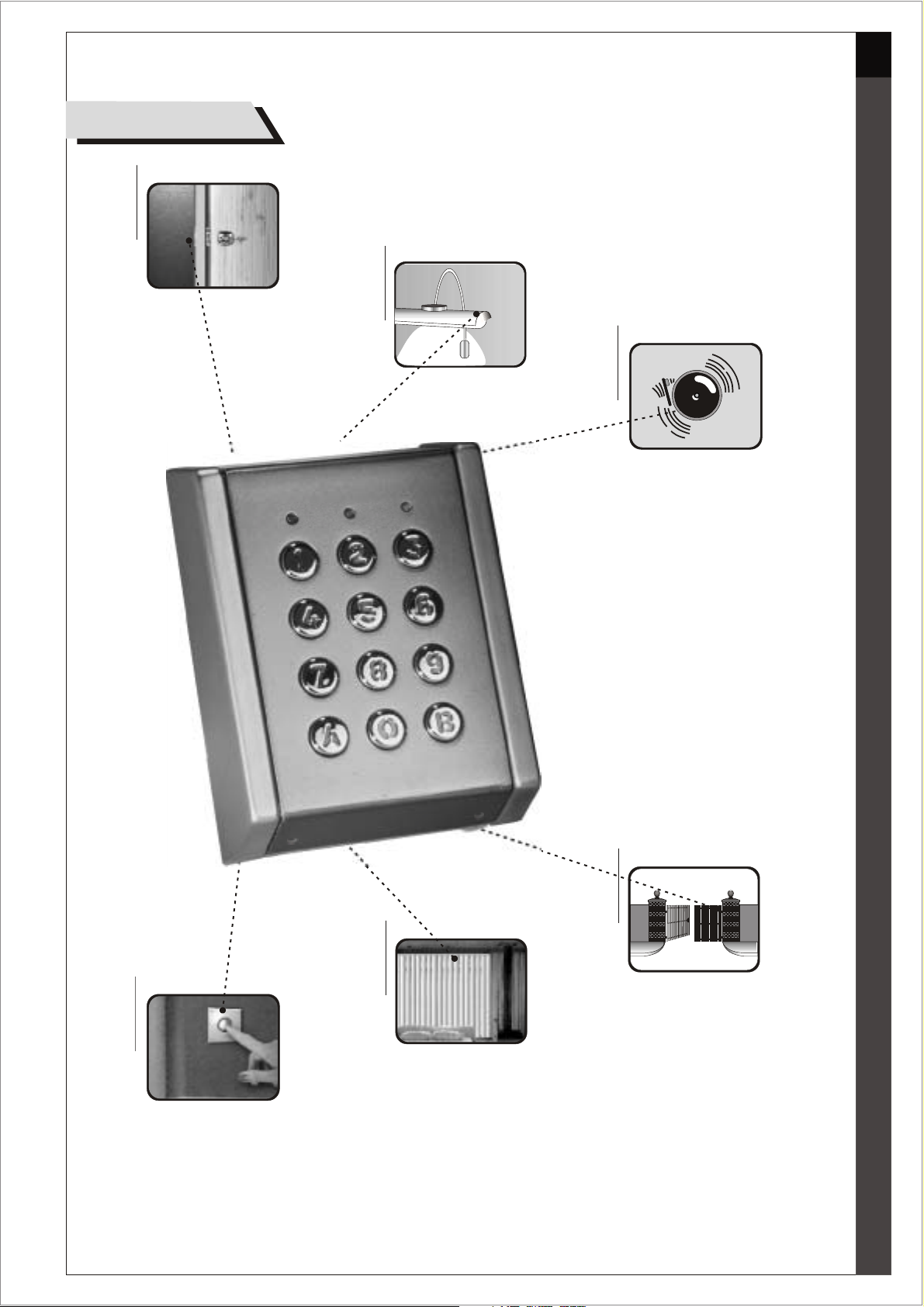
Applications
Door strike
3
Lights
Alarm
Push button
Gates
Blinds
Page 4
4
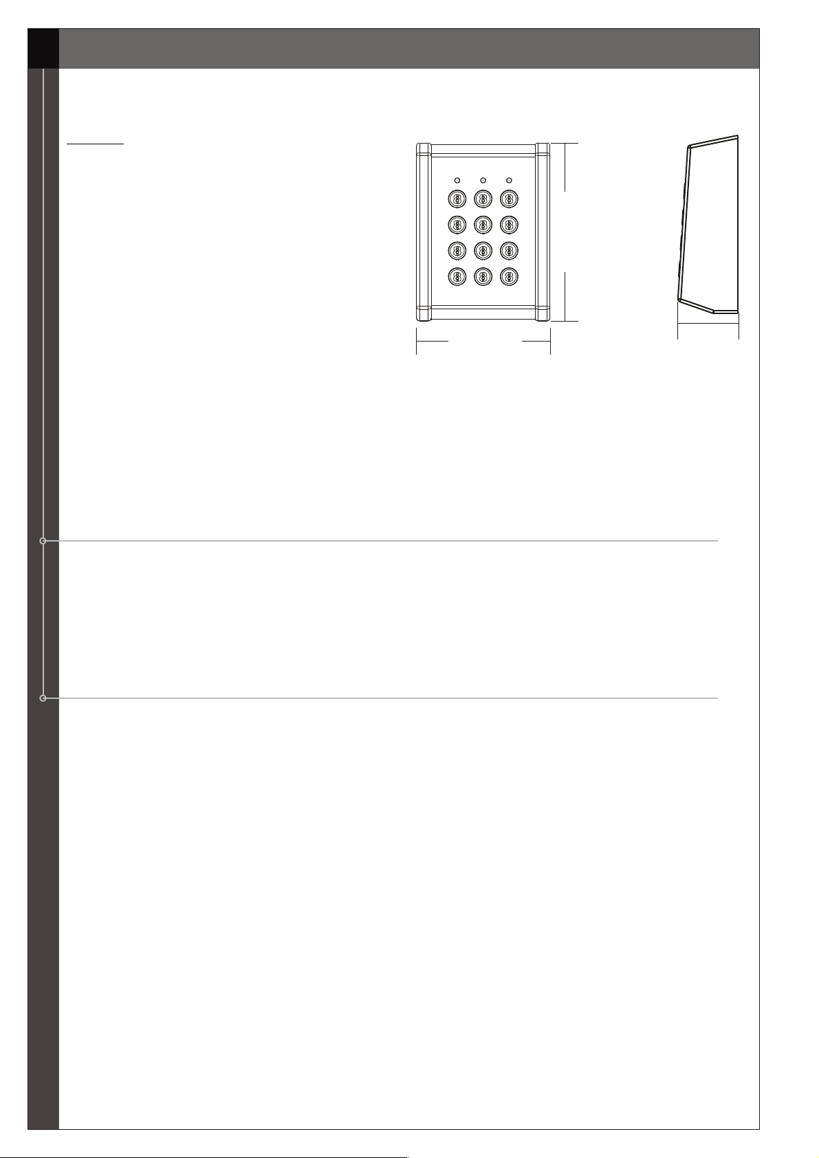
EX5 and EX7 are standalone keypads suitable for both access control and command solutions. They
can be either surface (52, 72 models) or flush (102 model) mounted.
Features:
: Operates on 12/24V AC/DC
: Backlit keys (metal/plastic keys
: Indoor/outdoor use
: 99 User codes (0 to 8 digits)
: 30 sec lockout after 8 invalid codes
: 2 Free tension LEDs (Red & Green)
: 2 Pushbuttons to operate relays
1.0 Introduction
1.0 Introduction
120mm
: 2 relays in EX5 and 4 relays in EX7
: Relay in latch (00) or pulsed mode (01 to 99 sec)
: Power switching regulator for longer product life
: EEPROM prevents data loss during power failure
: Peripherals connected via bi-directional CODIX bus
: Current consumption: Standby: 30mA,
EX5 Maximum: 120mA: EX7 Maximum: 150mA
1.1. Testing EX5/EX7
The keypad is delivered pre-programmed by the factory. Before programming the EX5/EX7, it can be
tested for its operation. These pre-assigned codes are only to be used for test purposes and must be
modified afterwards to ensure complete security against unauthorized usage.
To perform the test, connect the power supply to the keypad and enter code 1 2 3 A. Now, relay 1
should be activated. You may now disconnect the power supply and continue with the installation.
1.2. PLEASE READ CAREFULLY BEFORE INSTALLATION
What you can do with the EX5/EX7 keypad:
1. Program up to 99 User codes
2. Connect up to 3 peripheral units via the CODIX bus: Slave proximity reader, type MINI
Slave keypad, type INOX or ICX
3. EX5 drives 2 relay outputs (10A and 2A respectively), EX7 drives 4 relay outputs, 2A each
4. Connects up to 2 Exit button
What you cannot do:
1. Use a power supply with output voltage lower than 11V or higher than 28V.
2. Overload the relay outputs by connecting a load higher than 10A on relay 1 of EX5 and
2A on relay 2 of EX5 and all the relays of EX7.
3. Connect a voltage to the CODIX bus.
Good to know:
1. Each User can have his/her own individual code (0 to 8 digits long ) or proximity tag.
2. Ensure that the Master code is kept confidential as it is vital for programming purposes.
3. To gain access, enter the user code and press ”A”. E.g. 123+A
Default keypad settings:
The keypad is preset to the most common application using an electric strike.
Settings are as follows:
Default Master code = 000
All User codes are assigned to drive relay 1
Default User code 1 = 123
90mm
40mm
Page 5
2.0 Installation and wiring instructions
2.0 Installation and wiring instructions
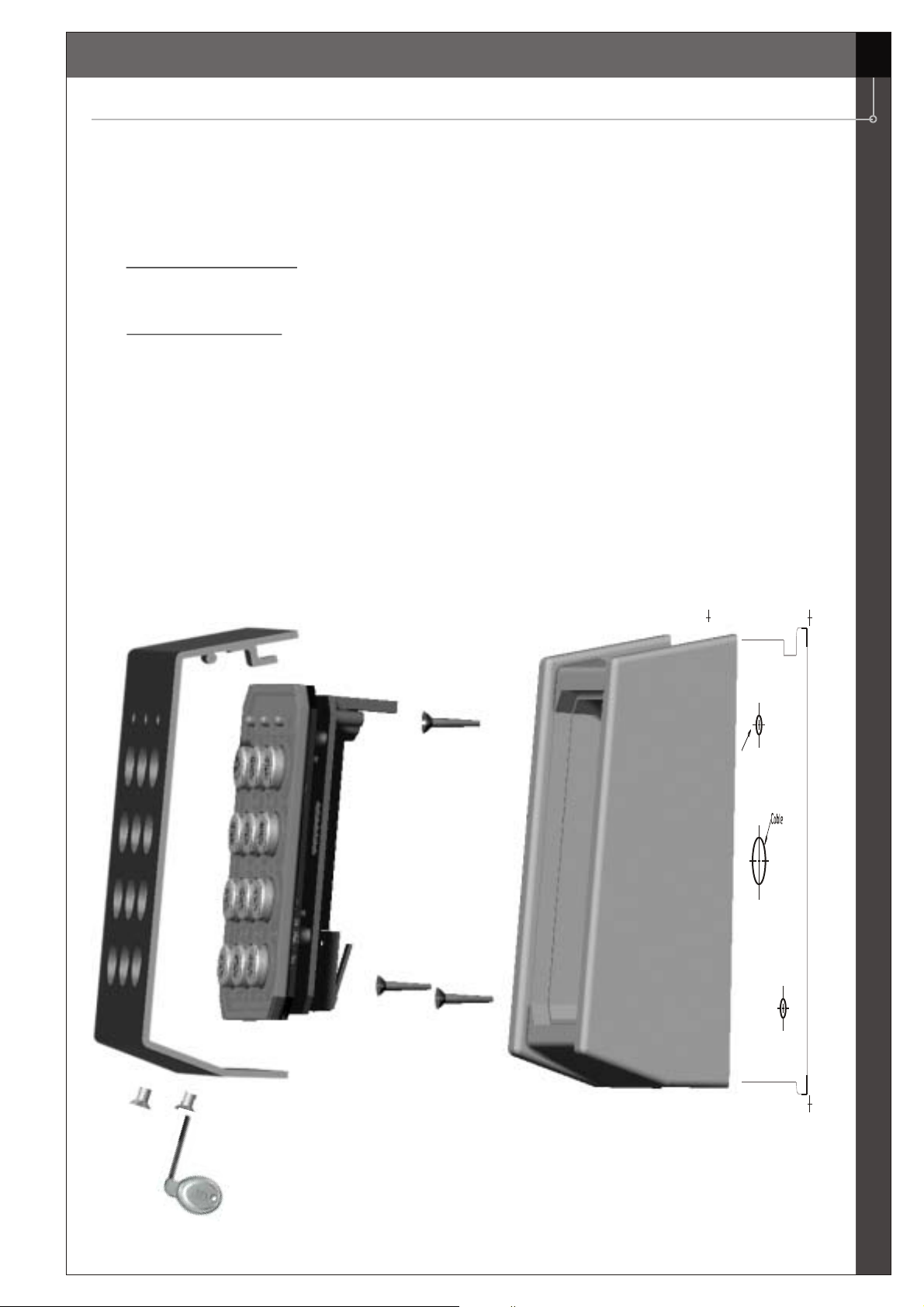
2.1. Mounting instructions
1. Determine an appropriate place to mount the keypad.
2. Stick the template and drill 3 holes as indicated on it.
3. Remove the top cover and then insert a screwdriver into the recess at the bottom of the housing
and separate keypad assembly from the housing.
4. Earthing is recommended for EX5 / EX7.
Cable through the wall
a. Route the interface cable from EX5/EX7 and power supply through holes provided for the same
on the housing.
Cable along the wall
b. In case wiring is carried out externally, then, using a nose-plier knock OFF the tab from base of
the top-cover and allow the cable to pass through. Ensure that the cable entry points are sealed
with silicone sealant.
5. Ensure that the wiring of the EX5/EX7 is carried out as per wiring instructions given in the
manual.
6. Fix the housing to the wall using 3 wall-mounting screws (8 x 30 CSK Philips) along with 3
rubber washers supplied.
7. Replace the keypad assembly and ensure that it is completely flush with the housing.
8. Finally replace the top cover and fix it with two M3 x 12 mm screws using the security screw driver
provided.
5
52
Page 6
6
2.2. Wiring instructions
Wiring terminals are located in the middle of the PCB and can be connected as described below.
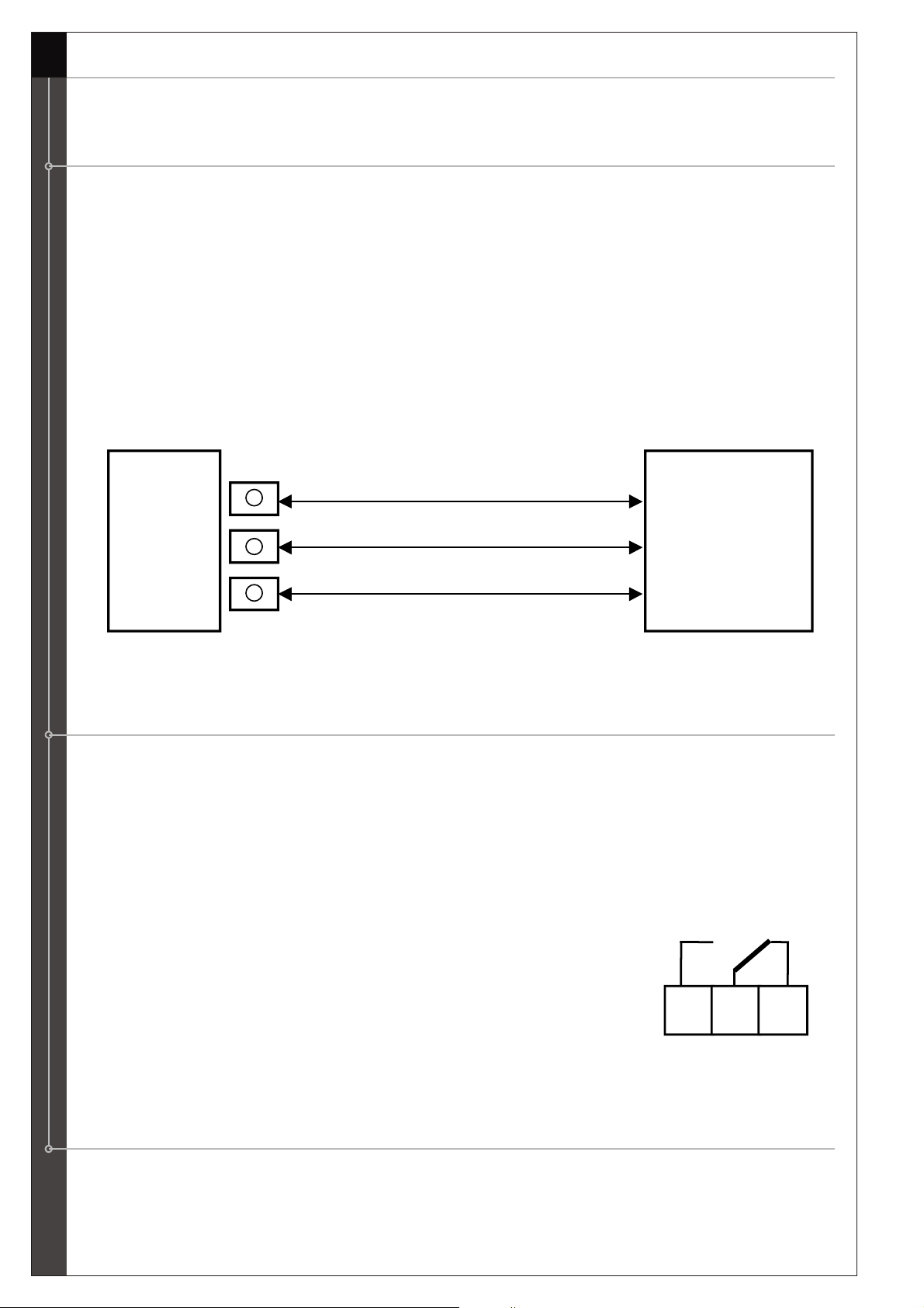
2.2.1. Connecting peripherals to the communication bus
The EX5/EX7 has a 3-wire CODIX data communication bus (GND, DATA, + 9V) that allows easy
connection of peripheral units (keypads or readers). The wiring is done between the BUS terminals of
the EX5/EX7 and the corresponding terminals of the peripheral units as specified in its technical
manual. The EX5/EX7 will automatically detect these peripheral units, so there is no need to
program the Master keypad to detect them.
Note: A maximum of 3 peripheral keypads/readers can be connected to EX5/EX7. The maximum
distance between the EX5/EX7 and the peripheral is 200m (100m if 2 or 3 peripherals are
connected to the EX5/EX7); the maximum distance between EX5/EX7 and the power supply is 50
meters. If the distance between the power supply and the EX5/EX7 exceeds 10 meters, then it is
advisable to connect only one peripheral (keypad or proximity reader) over a maximum distance of
100m.
EX5/EX7
+9V
DATA
GND
BUS
Peripheral
+
DATA
GND
NOTE: The CODIX connections on the keypad are only an output. No voltage should be
applied to these terminals to avoid damaging the keypad.
2.2.2. Connecting output relays
The EX5 has 2 relay outputs with the following characteristics:
Relay 1: 10A / 24V DC 120V AC
Relay 2: 2A / 24V AC/DC
The EX7 has 4 relay outputs with the following characteristics:
All 4 Relays: 2A / 24V AC/DC
Relay contacts are voltage-free switch contacts and can be connected as follows:
NO (Normally opened), C (Common), NC (Normally closed)
NO C NC
The relay terminals are located on the PCB as shown in connection diagram (refer “Overall
connection diagram”).
2.2.3. Connecting an electric strike to output relays
When an electric strike is connected, the power supply used must be sufficient to power both the
EX5 and the strike. As in some applications this might not be possible, the use of a separate
power supply for the door strike is recommended.
Page 7
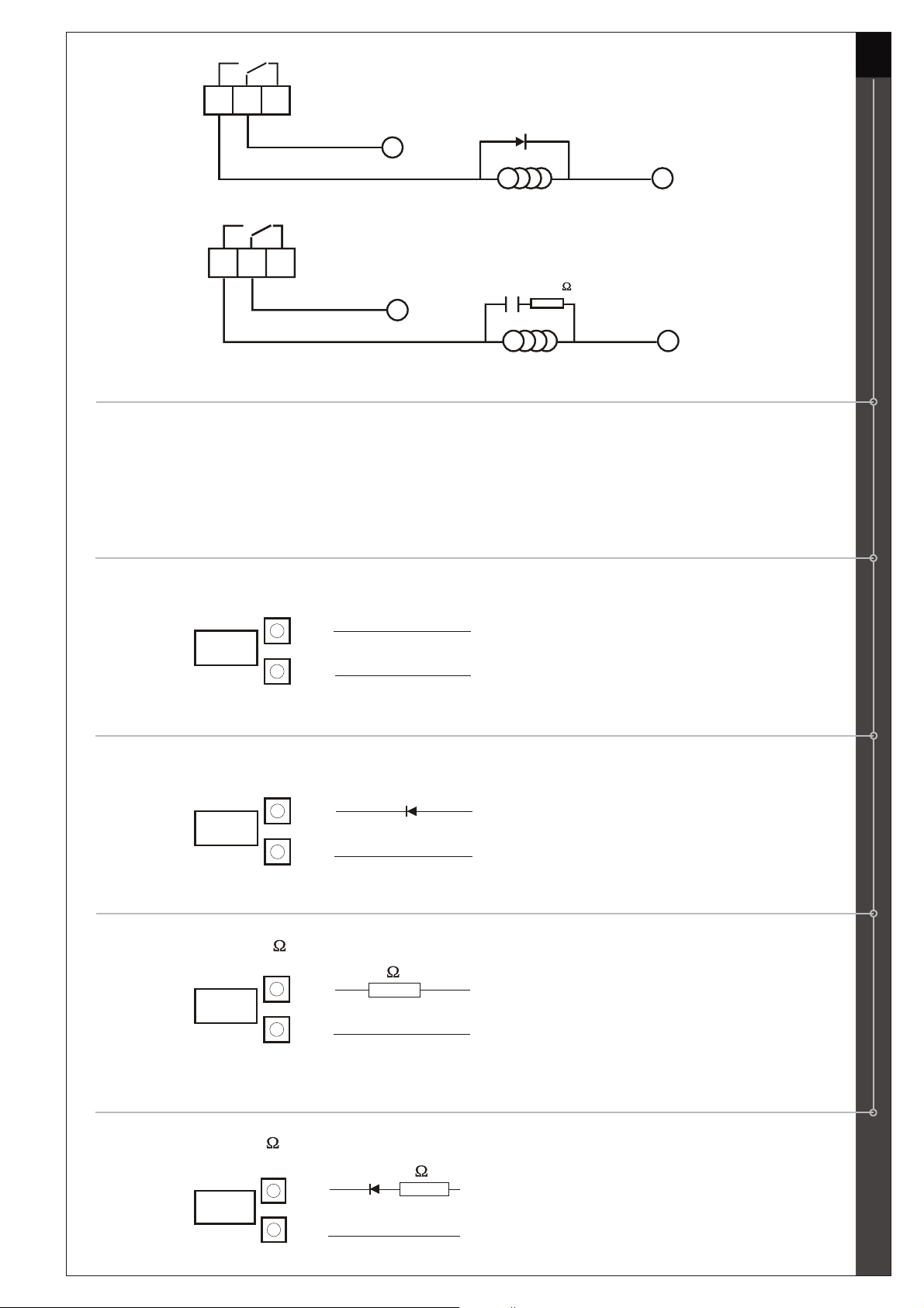
DC connection :
7
NO C NC
_
AC connection :
NO C NC
470 nF 10K - ½W
~
Diode
BY 251
+
Strike
Capacitor + Resistor
~
Strike
2.2.4. Connecting voltage free LEDs
EX5/EX7 is equipped with a red and a green LED, which can be driven externally. The connections
for these LEDs are as follows (refer “Overall connection diagram”): LR + and LR - = Red LED
LG + and LG - = Green LED
Connections are to be done as follows:
2.2.4.1. On 12V DC power
Connect straight as shown below:
LED
+(+V
12 DC)
- (Negative terminal power supply)
2.2.4.2. On 12V AC power
Connect a diode, type 1N4001 in series with the positive terminal of the LED:
+ (12V ~)
LED
- (12V ~)
2.2.4.3. On 24V DC power
Connect a resistor of 1k / 1W as shown below:
1k / 1W
LED
+(+V
24 DC)
- (Negative terminal power supply)
2.2.4.4. On 24V AC power
Connect a resistor of 1k / 1W and a diode, type 1N4001 in series with the positive terminal of the
LED:
+ (
LED
1k / 1W
24V ~)
- (24V ~)
Page 8

8
2.2.4.5. Connecting voltage free LEDs to indicate the relay
state
If required the voltage free LEDs can be used to light up each time and for as long as a relay
output is activated. For instance, the green LED can show the state of relay 1, the red LED can
show the state of relay 2. For example when the door strike is activated, the green LED lights up.
To do so, the following connections should be made (please refer “Connecting an electric strike
to the output relays”) for correct connection of the door strike to the relay:
DC connection:
NO C NC
AC connection:
NO C NC
Diode
BY 251
_
+
Strike
-
Capacitor + Resistor
470 nF 10K - ½W
~
Strike
-
+
LED
~
+
LED
2.2.5. Connecting Exit buttons
The EX5/EX7 unit offers the possibility to connect 2 normally open (NO) contacts in such a way
that once this contact is closed (e.g. by pressing an Exit button) an output relay of the EX5/EX7 is
activated. For instance, this contact can be used to connect an emergency Exit button to open
the door without entering either a code or presenting a tag.
EX5: Exit button 1 and Exit button 2 will automatically activate relay 1 and relay 2 respectively.
EX7: Refer “Assigning of relay to Exit buttons (EX7)”.
These connections can be found on:
Exit button 1 (PB1), Ground (GND) and Exit button 2 (PB2)
Pb1
GND
Pb2
Page 9

2.2.6. Connecting tamper switch
The tamper switch is a security contact (NO) to detect the opening or the tampering of the housing of
the EX5/EX7.
Once the keypad is installed on the wall, the contact will remain closed.
The connections for this tamper switch are as follows:
NO C
Tamp
2.2.7. Overall connection diagrams
EX5 EX7
9
3.0 Programming instructions
3.0 Programming instructions
Before you begin the programming, you need to enter into the programming mode by entering the
Master Code.
3.1. The Master code
The Master code enables you to start the programming on the EX5/EX7 keypad. The default Master
code as defined by the factory, is “000”. It is highly recommended to change the Master code from
the default factory setting for security purposes.
Page 10

10
3.1.1. Changing the Master code
It is possible to modify the Master code by performing the following steps:
Switch ON the power to the keypad.
1. Enter the Master code {either the default Master code (000)+B if this hasn't been changed
yet OR your personal Master code (e.g. 1997+B, where 1997 denotes the Master code
you have programmed)}. The yellow LED lights ON followed by a long beep.
2. Press 000.
3. Enter the NEW Master code of 1 to 8 digits (e.g.: 2578).
4. Confirm by pressing key A. Two short beeps are heard.
5. Quit the programming mode by pressing B. Yellow LED turns OFF.
E.g.: Based on factory code (for 1 time):
st
000 + B + 000 + 2578 + A + B
Based on personal Master code (assume personal Master code = 1997)
1997 + B + 000 + 2578 + A + B
3.1.2. Restore default factory settings and redefine a Master
code
Should the personal Master code be lost or forgotten, it is always possible to restore the default
factory setting and define a NEW Master code by performing the following steps:
Switch OFF the power to the keypad.
1. Open the housing of the unit and place the jumper in the closed position.
2. Switch on the power to the keypad. The yellow LED blinks followed by several beeps.
3. Put the jumper back in its original (opened) position.
The yellow LED remains ON followed by a long beep.
4. Close the housing of the unit.
Jumper Position
Closed
5. Press 000.
6. Enter the new Master code (1 to 8 digits, e.g.:2578).
7. Confirm by pressing key A. Two short beeps are heard.
8. Quit the programming mode by pressing B. The yellow LED turns OFF.
Opened
E.g.: 000 + 2578 + A + B
3.2. Programming EX5/EX7
3.2.1. Entering the programming mode
To enter the programming mode follow the instructions given below:
1. Enter your Master code.
2. Confirm by pressing key B. The yellow LED lights ON followed by a long beep.
Note: If the entered Master code is invalid, beeps and flashes for a period of 3 seconds
(beep...beep…) are indicated.
3.2.2. Programming the User codes
Note: For all examples below, it is assumed that the Master code is set to 2578.
Page 11

3.2.2.1. Installation with or without peripheral keypad
1. Enter the programming mode (refer to “Entering the programming mode”).
2. Press 0.
3. Enter the memory position (01 ... 99) of the User to be programmed (e.g. 01).
4. Enter the User code (e.g.: 12345).
5. Confirm by pressing key A. Two short beeps are heard.
Repeat steps 2 to 5 in order to program the other Users 02 to 99.
6. Quit the program by pressing key B.
E.g.: 2578 B + 0 + 01 + 12345 A + B
3.2.2.2. Installation with a peripheral proximity reader
Programming the proximity tags via the EX5/EX7 keypad.
1. Enter the programming mode (refer to “Entering the programming mode”).
2. Press 0.
3. Enter the memory position (01 ... 99) of the User to be programmed (e.g.: 0 )
2.
4. Present the tag in front of the proximity reader. Two short beeps are heard on the Master
keypad and one beep on the reader to indicate correct memorization.
Repeat steps 2 to 4 in order to program the other Users.
5. Quit the program by pressing key B.
11
E.g.: 2578 B + 0 + 02 + present the tag in front of slave reader + B
3.2.3. Assigning relays to codes
1. Enter the programming mode (refer to “Entering the programming mode”).
2. In case of EX5, press 3.
In case of EX7, press 7
3. Enter the memory position (01... 99) of the User code to be programmed (e.g.: 02 for
code 2).
4. Enter the number of the relay to be assigned (i.e. For EX5, 1 for relay 1, 2 for relay 2, or
1+2 for relay 1and 2 whereas for EX7, 1and/or 2 and/or 3 and/or 4 for relays 1,2,3 and 4
respectively).
5. Confirm by pressing key A. Two short beeps are heard.
6. Quit the program by pressing key B.
E.g. for EX5: 2578 B + 3 + 02 + 1+ A = code 2 activates relay 1
E.g. for EX7: 2578 B + 7 + 02 + 3+ A = code 2 activates relay 3
E.g. for EX7: 2578 B + 7 + 03 + 14+ A = code 3 activates relay 1 and 4
Note: The default factory setting automatically assigns all User codes to relay 1. Only when codes
are assigned to another relay, this needs to be redefined.
3.2.4 . Programming relays for ON/OFF mode or pulsed mode
1. Enter the programming mode (refer to “Entering the programming mode”).
2. Enter the number of the relay to be programmed (i.e. For EX5, 1 for relay 1or 2 for relay 2
whereas for EX7, 1 for relay1 or 2 for relay 2 or 3 for relay 3 or 4 for relay 4).
3. Enter: a. 00 for ON/OFF mode functioning.
b. 01 to 99 seconds for pulsed mode functioning.
4. Confirm by pressing key A. Two short beeps are heard.
Repeat steps 2 4 l
to in order to program the 2nd re ay.
5. Quit the program by pressing key B.
E.g.: 2578 B + 1 + 00 + A = ON/OFF (Relay 1)
Or 2578 B + 2 + 15 + A = Pulse 15 sec (Relay 2)
Page 12

12
3.2.5 . Assigning of relay to Exit buttons (EX7)
Note: This option is available only for the EX7 unit.
1. Enter the programming mode (refer to "Entering the programming mode").
2. Press 5 for Exit button 1 (PB1)
OR
Press 6 for Exit button 2 (PB2).
3. Enter the number of the relay to be assigned (i.e.: 1 and/or 2 and/or 3 and/or 4, for relays
1,2,3 and 4 respectively).
4. Confirm by pressing key A. Two short beeps are heard.
5. Quit the program by pressing key B.
E.g.: 2578 B + 5 + 1+ A = Assigning relay 1 to the Exit button 1 (PB1)
E.g.: 2578 B + 6 + 34+ A = Assigning relays 3 and 4 to the Exit button 2 (PB2)
3.2.6 . Quit programming mode
To quit the programming mode, press key B. The yellow LED turns OFF.
3.2.7. Deleting User codes / tags
3.2.7.1. To delete a single User code / tag
1. Enter the Master code.
2. Confirm by pressing key B. The yellow LED lights ON and a long beep is heard.
3. Press key 9.
4. Enter the memory position (01... 99) of the User code to be deleted (e.g.: 03 to delete User
code 3).
5. Confirm by pressing key A. Two short beeps are heard.
Repeat steps 3 to 5 if more codes need to be deleted.
6. Quit the program by pressing key B.
E.g.: 2578 B + 9 + 03 + A = Deleting User code 3
3.2.7.2. To delete all User codes / tags
1. Enter the Master code.
2. Confirm by pressing key B. The yellow LED lights ON and a long beep is heard.
3. Press keys 8, then enter 99. A long warning beep will be heard.
4. Confirm by pressing key A. Two short beeps are heard.
5. Quit the program by pressing key B.
E.g. : 2578 B + 8+99 + A + B
3.2.8. Overview of the programming menu of EX5
Entering programming mode:
Enter Master code + B (Yellow LED lights ON + long beep)
Program new Users: (once entered in programming mode)
For keypad codes: 0 + (01…99) + (User code) + A
For proximity tags: 0 + (01…99) + (User tag)
Page 13

Assign relays to User codes: (once entered in programming mode)
3 + (01…99) + (1 or 2 or 12) + A with 1 = relay 1
Defining functioning mode for relays: (once entered in programming mode)
(1 or 2) + (00 for ON/OFF mode or 01...99 sec for pulsed mode) + A
with 1 = relay 1
Delete a single User code / tag: (once entered in programming mode)
9 + (01…99) + A
Delete all User codes / tags: (once entered in programming mode)
8 + 99 + A
Quit programming mode : (once entered in programming mode)
Press key B (Yellow LED turns OFF)
13
2 = relay 2
12 =relays 1and 2
2 = relay 2
3.2.9. Overview of the programming menu of EX7
Entering programming mode:
Enter Master code + B (Yellow LED lights ON + long beep)
Program new Users: (once entered in programming mode)
For keypad codes: 0 + (01…99) + (User code) + A
For proximity tags: 0 + (01…99) + (User tag)
Defining functioning mode for relays: (once entered in programming mode)
(1 or 2 or 3 or 4) + (00 for ON/OFF mode or 01...99 s for pulsed mode) + A
with 1/2/3/4 = relays 1 / 2 / 3 / 4 respectively
Assigning relay to exit button: (once entered in programming mode
(5 or 6) + (1 and/or 2 and/or 3 and/or 4) + A
with 1,2,3,4 = relays 1,2,3 and 4 respectively
Assign relays to User codes: (once entered in programming mode)
7 + (01…99) + (1 and/or 2 and/or 3 and/or 4) + A
With 1,2,3,4 = relays 1,2,3 and 4 respectively
Delete all User codes / tags: (once entered in programming mode)
8 + 99 + A
Delete a single User code / tag: (once entered in programming mode)
9 + (01…99) + A
Quit programming mode: (once entered in programming mode)
Press key B (Yellow LED turns OFF)
Page 14

14
4.0 Address register
4.0 Address register
{{01...99}}
Roger
Allan 02
Susan
01 123
03
01
02
03
04
05
06
07
08
09
10
11
12
13
14
15
16
17
18
19
20
21
22
23
24
25
26
27
28
29
30
31
32
33
34
35
36
37
38
39
40
41
42
43
44
45
46
47
48
49
50
1 2
456
789
 Loading...