

Page 1
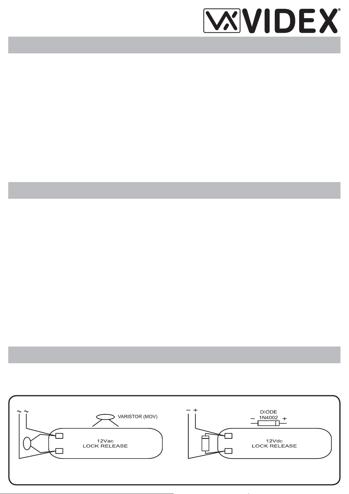
Fig.1A Fig.1B
DK8K-1/2
Installation Instructions
Digiphone Kit
Istruzioni di installazione
NORME GENERALI DI INSTALLAZIONE GENERAL DIRECTIONS FOR INSTALLATION
Per eseguire una corretta installazione è necessario impiegare esclusivamente parti VIDEX, seguire scrupolosamente quanto indicato negli
schemi di collegamento e tenere presenti le norme generali d’installazione:
• Realizzare gli impianti secondo le vigenti normative nazionali ed in
ogni caso si consiglia di prevedere, per i conduttori dell’impianto, una
canalizzazione distinta da quella della linea elettrica (vedi paragrafo seguente per il collegamento alla linea elettrica e l’installazione
dell’alimentatore);
• Impiegare conduttori con sezioni tali da avere:
- resistenza complessiva inferiore a 10Ω per quelli della linea fonica
e di comando;
- resistenza complessiva inferiore a 3Ω per quelli della serratura e di
alimentazione;
• Verifi care le connessioni prima di dare alimentazione all’impianto;
• Alimentare l’impianto ed eseguire il collaudo verifi candone tutte le fun-
zioni.
COLLEGAMENTO ALLA RETE ELETTRICA
ED INSTALLAZIONE DELL’ALIMENTATORE
La realizzazione dell’impianto deve essere eseguita nel rispetto delle
vigenti normative nazionali, in particolare si raccomanda di:
• Collegare l’impianto alla rete elettrica tramite un dispositivo di interruzione omnipolare che abbia una distanza di separazione del contatto
di almeno 3mm per ciascun polo e che sia in grado di disconnettere
tutti i poli simultaneamente;
• Il dispositivo di interruzione omnipolare deve essere posizionato in un
luogo tale da consentirne un facile accesso in caso di necessità.
In order to achieve the best results from the schematics described it is
necessary to install only original VIDEX equipment, strictly keeping to
the items indicated on each schematic and follow these General Directions for Installation:
• The system must be installed according to national rules in force, in
any case the running of cables of any intercom unit must be carried
out separately from the mains (see the next paragraph for connection
to mains and power supply installation);
• All multipair cables should be compliant to CW1308 specifi cation
(0.5mm twisted pair telephone cable.
• Cables for speech line and service should have a max resistance of
10Ω
• Lock release wires should be doubled up (Lock release wires and
power supply wires should have a max resistance of 3Ω);
• The cables sizes above can be used for distances up to 50m. On
distances above 50m the cable sizes should be increased to keep the
overall resistance of the cable below the RESISTANCES indicated
above;
• Double check the connections before power up;
• Power up the system then check all functions.
CONNECTION TO MAINS AND
POWER SUPPLY MOUNTING INSTRUCTION
The system must be installed according to national rules in force, in
particular we recommend to:
• Connect the system to the mains through an all-pole circuit breaker
which shall have contact separation of at least 3mm in each pole and
shall disconnect all poles simultaneously;
• The all-pole circuit breaker shall be placed for easy access and the
switch shall remain readily operable.
Installazione dell’alimentatore
• Rimuovere i coperchi copri-morsetti svitando le relative viti e tirandoli
verso l’alto;
• Fissare l’alimentatore su barra DIN o direttamente a parete utilizzando le viti ed i relativi tasselli ad espansione forniti a corredo;
• Togliere la tensione di rete tramite il dispositivo sopra indicato ed eseguire le connessioni come previsto dagli schemi proposti (la connessione verso la rete va effettuata in base alla tensione disponibile 127
o 230Vac).
• Verifi care che non vi siano errori di connessione e che i fi li siano ben
serrati nei morsetti;
• Inserire a scatto i coperchi copri-morsetti e fi ssarli tramite le relative
viti;
• Eseguiti tutti i collegamenti, dare tensione all’impianto.
AZIONAMENTO SERRATURA
PROTEZIONE DAI DISTURBI
L’azionamento della serratura elettrica può provocare degli spike, per
evitare tale inconveniente si consiglia di collegare tra i terminali della
serratura un varistore (Fig.1A) o un diodo (Fig.1B) a seconda che la
serratura sia in alternata o in continua.
Power Supply Installation
• Remove the terminal side covers by unscrewing the retaining
screws;
• Fix the power supply to a DIN bar or directly to the wall using two
expansion type screws;
• Switch off the mains using the circuit breaker mentioned above and
then make the connections as shown on the installation diagrams;
• Check the connections and secure the wires into the terminals;
• Replace the terminal covers and fi x them using the relevant screws;
• When all connections are made, restore the mains.
LOCK RELEASE
BACK EMF PROTECTION
A MOV (VARISTOR) must be fi tted across the terminals on AC lock
release (Fig.1A) and a diode must be fi tted across the terminals on a
DC lock release (Fig.1B) to suppress back EMF voltages. Connect this
components to the lock releases as shown in fi gures.
DK8K 1.0 05/10/07 06/09/10
Page 2
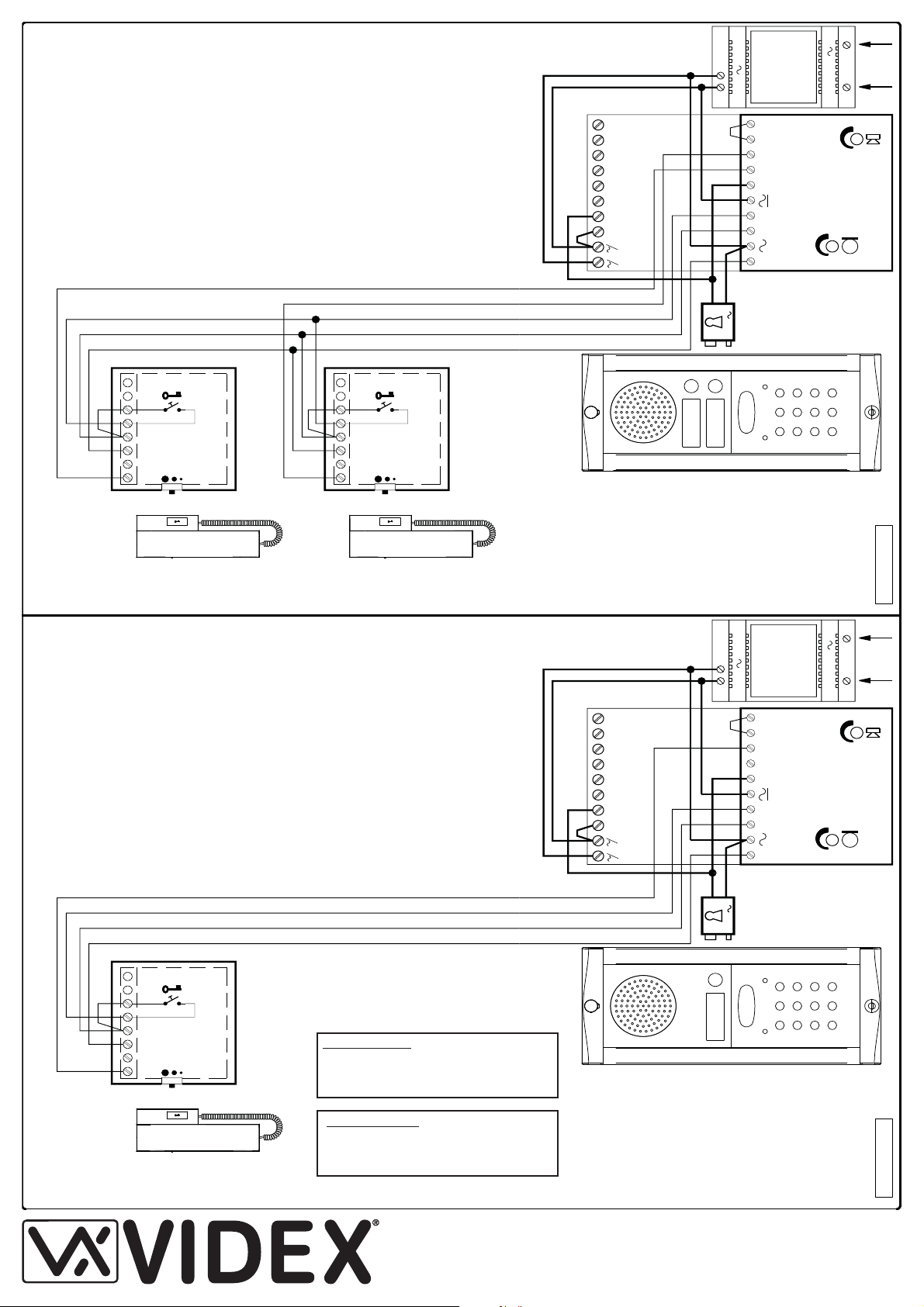
ART.DK8K-1.. DK8K-1S.. ART.DK8K-2.. DK8K-2S..
Art.3011
1
4 62 9135 8
*
- Regolazione volume della
nota elettronica (3 livelli).
- Call tone volume control
(3 Levels).
- Régulation du volume de
l'appel électronique
(sur 3 niveaux).
- Lautstärkeregulierung des
elektronischen Rufs
(auf 3 Niveaus).
- Control de volumen del
tono electrónico (3 niveles)
- Controle de volume (3
nÍveis) de chamada
electrónica.
*
ART.3011
- Citofono
- Intercom
- Innenstelle
- Poste d'appartement
- Teléfono
- Telefone
ART.321
- Trasformatore
- Trasformer
- Trafo
- Transformateur
- Transformador
- Transformador
ART.8836M-2..
- Pulsantiera con portiere
elettrico
- Front panel with built in
audio amplifier
- Aussenstelle mit
Sprecheinheit
- Platine de rue avec groupe
phonie
- Unidad de habla/Botonera
con parlante
- Botoneira com porteiro eléctrico
SE
- Serratura elettrica
(non inclusa)
- Electric lock
(not included)
- Elektrisches Turschloß
(nicht imbegriffen)
- Serrure électrique
(non incluse)
- Cerradura elèctrica
(no incluida)
- Testa eléctrica (não incluída)
50/60 Hz
230V
230V
12V
ART.321
12V
SE
Art.8836M-2
21
3
SP
2
PC
11
C
9
2
Art.3011
*
VIDEX
642135 8
VIDEX
ART.3011
- Citofono
- Intercom
- Innenstelle
- Poste d'appartement
- Teléfono
- Telefone
ART.321
- Trasformatore
- Trasformer
- Trafo
- Transformateur
- Transformador
- Transformador
ART.8836M-1..
- Pulsantiera con portiere
elettrico
- Front panel with built in
audio amplifier
- Aussenstelle mit
Sprecheinheit
- Platine de rue avec groupe
phonie
- Unidad de habla/Botonera
con parlante
- Botoneira com porteiro eléctrico
SE
- Serratura elettrica
(non inclusa)
- Electric lock
(not included)
- Elektrisches Turschloß
(nicht imbegriffen)
- Serrure électrique
(non incluse)
- Cerradura elèctrica
(no incluida)
- Testa eléctrica (não incluída)
12V
SE
12
ART.321
50/60 Hz
Art.8836M-1
S
3
P
2
C
11
P
230V
230V
12V
C
8591264 3
Art.3011
1
*
VIDEX
*
- Regolazione volume della
nota elettronica (3 livelli).
- Call tone volume control
(3 Levels).
- Régulation du volume de
l'appel électronique
(sur 3 niveaux).
- Lautstärkeregulierung des
elektronischen Rufs
(auf 3 Niveaus).
- Control de volumen del
tono electrónico (3 niveles)
- Controle de volume (3
nÍveis) de chamada
electrónica.
12-24Vac/dc
SW1
SW2
NC2
NO2
C2
NC1
NO1
C1
+
Art.8800
12-24Vac/dc
SW1
SW2
NC2
NO2
C2
NC1
NO1
C1
+
Art.8800
DK8K-001-3011 DK8K-001-3011
Si raccomanda
di far installare il presente dispositivo
esclusivamente da personale qualifi cato
We recommend
This equipment is installed by a Competent Electrician, Security or Communications Engineer
Factory - Offi ce (All Countries Support)
VIDEX ELECTRONICS S.p.A. Via del lavoro,1 63020 MONTEGIBERTO (AP) - ITALY
Phone: (+39) 0734 - 631669 Fax: (+39) 0734 - 632475 www.videx.it e-mail: info@videx.it
Northern UK Offi ce (Only UK Support)
VIDEX LTD Unit 5-7 Chillingam Industrial Estate Chapman Street NEWCASTLE UPON TYNE Ne6 2XX
Phone: 0191 2243174 Fax: 0191 - 2241559 www.videx-security.com
DK8K 1.0 05/10/07 06/09/10
Page 3

Instructions d’installation
Art.VX8800
Istruzioni di installazione
MODELLI MODELS
VX8800 Modulo a 2 Relè con illuminazione tastiera
VX8800 Module 2 Relay with keypad illumination LEDs
CARATTERISTICHE FEATURES
Sistema di controllo accessi con 2 codici e 2 uscite relè.
• Codice di accesso al menù di programmazione confi gurabile (da 4 ad 8 cifre).
• Impostazione di ciascun relè per l’attivazione temporizzata (da 1 a 99 secondi)
o la commutazione (00 nella programmazione del tempo relè).
• Possibilità di attivare i Relè 1 e 2 collegando a massa rispettivamente i morsetti
“SW1” ed “SW2”. I relè funzioneranno per il tempo programmato.
• La tastiera emette dei segnali acustici durante l’utilizzo ed è dotata di autoprotezione in caso di inserimento di codici errati (segnale acustico della durata
di 4 o più secondi).
• La tastiera è dotata di illuminazione e di due LED per indicare quanto segue:
- Inserimento di un codice corretto (LED verde acceso per 2 secondi).
- Menù di programmazione attivo (LED rosso acceso).
• Contatti relè (C, NO, NC) puliti, 24Vac/dc 5Amax.
• Tensione di alimentazione: 12/24Vac/dc, 2VA.
• Temperatura di lavoro: -10 +50°C
Access control system with 2 codes and 2 Relay outputs.
• Engineer’s code to enter into the “Programming Menu” ( from 4 to 8 digits).
• Programming of the activation time of each relay from 1 up to 99 seconds or
latching.
• Possibility to activate relay 1 by shorting terminal ”SW1” to GND and relay 2 by
shorting terminal “SW2” to GND. Both relays will operate for the programmed
time.
• Keypad gives an acoustic (buzzer) signal during the entering of codes and a
continuous melody for 4 or more seconds, according to the number of mistakes
(self protection).
• Keypad includes panel illumination and 2 LED’s to show the following:
- Correct relay code (green LED on for 2 seconds).
- Red LED to indicate when in the “programming menu”.
• Contacts of the relays are available ( N.O and N.C) with 5A max 24Vac/dc.
• Power requirements: 12/24V AC/DC, 2VA.
• Working temperature: -10 +50°C
FUNZIONAMENTO OPERATION
Per utilizzare il sistema, digitale il codice e premere “ENTER”, il LED verde si
accende ed il relè funzionerà per il tempo programmato. Per disattivare un relè
(impostato per l’attivazione temporizzata o a commutazione di stato), digitare lo
stesso codice e premere “CLEAR”. Se viene digitato un codice errato, la tastiera
emettere un segnale acustico continuo della durata di 4 o più secondi in base
al numero di errori.
T o use the system, type in the programmed code and press “ENTER” , the green
LED will illuminate and the relay will operate for the programmed time.T o cancel
remain open time, type in the same code and press “CLEAR”. If a wrong code
is entered, a continuous melody will sound for 4 or more seconds, according to
the number of mistakes.
INIZIALIZZAZIONE INITIALIZATION
Terminata l’installazione secondo lo schema proposto, dare alimentazione
all’impianto e procedere alla programmazione dell’unità seguendo il relativo
fl owchart di programmazione.
Premere Enter
(Il LED rosso si accende)
Premere Enter
(Segnale acustico)
Premere Enter
(Segnale acustico)
Premere Enter
(Segnale acustico)
Premere Enter
(Segnale acustico)
DIGITARE IL
“MASTER CODE”
CONFERMARE O
CAMBIARE IL
“MASTER CODE”
DIGITARE IL
CODICE RELÈ 1
DIGITARE IL
TEMPO RELÈ 1
DIGITARE IL
CODICE RELÈ 2
DIGITARE IL
TEMPO RELÈ 2
6 V O LTE 1 “111111” IMPOSTAZIONE DI FABBRICA
DIGITARE NUOVAMENTE
6 VOLTE 1 O UN NUOVO
CODICE DA 4 A 8 CIFRE
CODICE DI ATTIVAZIONE
RELÈ 1, DA 4 A 8 CIFRE
DUE CIFRE (DA 01 A 99)
ES. 05=5 SECONDI
00= COMM. DI STATO
CODICE DI ATTIVAZIONE
RELÈ 2, DA 4 A 8 CIFRE
DUE CIFRE (DA 01 A 99)
ES. 05=5 SECONDI
When the installation is concluded and carried out according to the wiring diagram, power up the system and program it by following the “VX8800 PROGRAMMING” Flow Chart.
ENTER
“ENGINEER’S
CODE”
Press Enter
(Red LED will be ON)
CONFIRM OR
CHANGE
“ENGINEER’S
CODE”
Press Enter
(Melody)
ENTER
“ACCESS 1 CODE”
Press Enter
(Melody)
ENTER
“ACCESS 1 TIME”
Press Enter
(Melody)
ENTER
“ACCESS 2 CODE”
Press Enter
(Melody)
ENTER
“ACCESS 2 TIME”
FIRST TIME SIX TIMES 1
“111111” FACTORY PRESET
TYPE AGAIN SIX TIMES “1” OR
THE NEW ENGINEER’S CODE 4
TO 8 DIGITS
CODE TO ENABLE
RELAY 1
4 TO 8 DIGITS
TWO DIGITS (01 TO 99)
I.E. 05=5 SECONDS
00= REMAIN OPEN
CODE TO ENABLE
RELAY 2
4 TO 8 DIGITS
TWO DIGITS (01 TO 99)
i.e. 05 for 5 seconds
Premere Enter
(Segnale acustico)
IL SISTEMA È
PRONTO ALL’USO
IL LED ROSSO SI SPEGNE
VX8800 1.0 05/10/07 01/06/10
Press Enter
(Melody)
SYSTEM READY TO
USE
RED LED WILL BE OFF
Page 4

PROGRAMMAZIONE PROGRAMMING
FARE RIFERIMENTO AL FLOW CHART
• Digitare il “MASTER CODE”: 6 volte “1” (111111 impostazione di fabbrica) e
premere ENTER (il LED rosso si accende).
• Confermare il “MASTER CODE” (digitandolo nuovamente) o digitarne uno
nuovo (da 4 ad 8 cifre) quindi premere ENTER (segnale acustico). Premendo
due volte ENTER senza modifi care il “MASTER CODE” si esce dalla program-
mazione.
• Digitare il codice di attivazione (da 4 ad 8 cifre) del “RELè 1” quindi premere
ENTER (segnale acustico).
• Digitare il tempo di funzionamento del “RELÉ 1” (2 cifre da 01 a 99 Es.05=5 secondi 00=Commutazione di stato) quindi premere ENTER (segnale acustico).
• Digitare il codice di attivazione (da 4 ad 8 cifre) del “RELè 2” quindi premere
ENTER (segnale acustico).
• Digitare il tempo di funzionamento del “RELÉ 2” quindi premere ENTER (segnale acustico).
• Il sistema è pronto all’uso (il LED rosso si spegne).
ISTRUZIONI PER RIPORTARE IL SISTEMA AL CODICE MASTER
IMPOSTATO DI FABBRICA
• Togliere l’alimentazione alla tastiera.
• Tenendo premuto il tasto “ENTER”, dare nuovamente alimentazione alla tastiera.
• Rilasciare il tasto “ENTER”.
• Il MASTER CODE è nuovamente quello di fabbrica “111111 ” (6 volte “1”).
• Procedere con la nuova programmazione.
NOTE
• Per disattivare uno dei relè mentre è in funzione, digitare il relativo codice
quindi premere il tasto “CLEAR”.
• Per far funzionare i relè contemporaneamente, impostare lo stesso codice di
attivazione per ciascun relè.
• Se viene digitato un codice errato, l’unità si blocca per 5 secondi: il tempo di
blocco aumenta in base al numero di errati inserimenti. L’unità funzionerà solo
digitando un codice corretto.
REFER ALSO TO FLOW CHART
• Enter “ENGINEER’S CODE”: fi rst time type six times “1” (111111 factory pre-
set) and press ENTER (The red LED will illuminate).
• Confi rm “ENGINEER’S CODE” (typing again the same) or type the new code
(4 to 8 digits) then press ENTER (Melody). Pressing twice the ENTER button
without changing the “ENGINEER’S CODE”, will exit from the programming.
• Enter the code (4 to 8 digits) to enable “RELAY 1” (ACCESS 1) or re-enter the
existing code then press ENTER (Melody).
• Enter the “RELAY 1” operation time (2 digits 01 to 99 I.E. 05=5 seconds, 00=
remain open time) or re-enter the existing time then press ENTER (Melody).
• Enter the code (4 to 8 digits) to enable “RELAY 2” (ACCESS 2) or re-enter the
existing code then press ENTER (Melody).
• Enter the “RELAY 2” operation time (2 digits 01 to 99 I.E. 05=5 seconds, 00=
remain open time) or re-enter the existing time then press ENTER (Melody).
• The system is ready to use (the red LED will be off).
INSTRUCTION TO RETURN SYSTEM TO PRESET ENGINEER’S
FACTORY CODE
• Turn off power to code lock.
• Keep “ENTER” button pressed while turning back on the power to the code
lock.
• Release “ENTER” button.
• The master code is now set at factory engineer’s code “111111” (six times “1”).
• Proceed with programming for a new system.
NOTES
• To switch off any relay while operating, type in the relevant code then press
the “CLEAR” button.
• To operate relays together, set the same code for each relay.
• If a wrong code is entered, the system will lock out for 5 seconds which will increase each time a wrong code is entered. The system will operate only when
the correct code is entered.
NORME GENERALI D’INSTALLAZIONE GENERAL DIRECTIONS FOR INSTALLATION
Per eseguire una corretta installazione è necessario impiegare esclusivamente
parti VIDEX, seguire con scrupolo quanto indicato negli schemi di collegamento
e tenere presenti le norme generali d’installazione:
• Realizzare gli impianti secondo le vigenti normative nazionali ed in ogni caso si
consiglia di prevedere, per i conduttori dell’impianto, una canalizzazione distinta da quella della linea elettrica (vedi paragrafo seguente per il collegamento
alla linea elettrica e l’installazione dell’alimentatore);
• Impiegare conduttori con sezioni tali da avere:
- resistenza complessiva inferiore a 10 per quelli della linea fonica e di comando;
- resistenza complessiva inferiore a 3 per quelli della serratura e di alimentazione;
• Verifi care le connessioni prima di dare alimentazione all’impianto;
• Alimentare l’impianto ed eseguire il collaudo verifi candone tutte le funzioni
AZIONAMENTO SERRATURA - PROTEZIONE DAI DISTURBI
L’azionamento della serratura elettrica può provocare degli spike, per evitare
tale inconveniente si consiglia di collegare tra i terminali della serratura un varistore (Fig.1A) o un diodo (Fig.1B) a seconda che la serratura sia in alternata
o in continua.
In order to achieve the best results from the schematics described it is necessary
to install only original VIDEX equipment, strictly keeping to the items indicated
on each schematic and follow these General Directions for Installation:
• The system must be installed according to national rules in force, in any case
the running of cables of any intercom unit must be carried out separately from
the mains;
• All multipair cables should be compliant to CW1308 specifi cation (0.5mm twist-
ed pair telephone cable.
- Cables for speech line and service should have a max resistance of 10
- Lock release wires should be doubled up (Lock release wires and pow-
er supply wires should have a max resistance of 3 );
• The cable sizes above can be used for distances up to 50m. On distances
above 50m the cable sizes should be increased to keep the overall resistance
of the cable below the RESISTANCES indicated above;
• Double check the connections before power up;
• Power up the system then check all functions.
LOCK RELEASE BACK EMF PROTECTION
A MOV (VARISTOR) must be fi tted across the terminals on AC lock release
(Fig.1A) and a diode must be fi tted across the terminals on a DC lock release
(Fig.1B) to suppress back EMF voltages. Connect this components to the lock
releases as shown in fi gures.
Factory - Offi ce (All Countries Support)
VIDEX ELECTRONICS S.p.A. Via del lavoro,1 63020 MONTEGIBERTO (AP) - ITALY
Phone: (+39) 0734 - 631669 Fax: (+39) 0734 - 632475 www.videx.it e-mail: info@videx.it
Northern UK Offi ce (Only UK Support)
VIDEX LTD Unit 5-7 Chillingam Industrial Estate Chapman Street NEWCASTLE UPON TYNE Ne6 2XX
Phone: 0191 2243174 Fax: 0191 - 2241559 www.videx-security.com
VX8800 1.0 05/10/07 01/06/10
Page 5

SE
0
ART.522
230V
FUSE
12V
Door Open Button
Lamp Button
ART.321
LAMP
24Vac/dc 5A max
POWER
VX8800
+
-
C1
NC1NO1 NO2C2NC2 SW1
SW2
12¸ 24
Vac/dc
VX8800.dwg
GUIDA ALLA RIPROGRAMMAZIONE RE-PROGRAMMING GUIDE
DIGITARE IL CODI-
Premere Enter
(il LED rosso si accende*)
Premere Enter
Premere Enter
Premere Enter
Ripetere le stesse operazioni per il relé 2
Notes:
* Se il LED rosso non si accende, il codice installatore non è corretto. Seguire
le istruzioni per ripristinare il codice installatore di fabbrica.
** Al primo passaggio del fl ow chart si sta operando sul relé 1 mentre al secon-
do passaggio sul relé 2.
Codice Installatore
Codice Relé 1
Codice Relé 2
CE INSTALLATORE
DIGITARE NUOVAMENTE IL CODICE
DIGITARE IL CODI-
CE DI ACCESSO
DIGITARE IL TEMPO
DI ATTIVAZIONE
RELÈ
SI
ALTRI
RELÈ?
PREMERE 2 VOLTE
ENTER PER
NO
USCIRE
ALTERNATIVELY ENTER
A NEW ENGINEER’S
CODE (4 TO 8 DIGITS)
RELAY CODE (4-8 DIGITS) OPERATE THE
DOOR OR GATE.**
TWO DIGITS (01-99 Sec
OR 00 FOR REMAIN
OPEN)
ENTER THE
Press Enter
(Red light will illuminate*)
Press Enter
Press Enter
Press Enter
Repeat steps for relay 2
Notes:
* If the red light does not illuminate, the engineer ’s code is incorrect. Follow
instructions to return system to preset engineer’s factory code.
** On the fi rst loop of the fl ow chart its relay 1 while second loop is relay 2.
Engineer’s Code
Relay 1 Code
Relay 2 Code
ENGINEER’S CODE
RE-ENTER THE
ENGINEER’S CODE
ENTER ACCESS
CODE
ENTER ACCESS
TIME
YES
MORE
DOORS ?
PRESS ENTER
TWICE TO EXIT
PROGRAMMING
NO
ALTERNATIVELY ENTER
A NEW ENGINEER’S
CODE (4 TO 8 DIGITS)
RELAY CODE (4-8 DIGITS) OPERATE THE
DOOR OR GATE.**
TWO DIGITS (01-99 Sec
OR 00 FOR REMAIN
OPEN)
Tempo Relé 1
Tempo Relé 2
Relay 1 Time
Relay 2 Time
VX8800 1.0 05/10/07 01/06/10
Page 6

12Vdc
1N4002
FAIL SAFE DC LOCK
ART.521
230V
0
+
PUSH TO EXIT
FAIL SAFE LOCK RELEASE
12Vac
FAIL SECURE AC LOCK
PUSH TO EXIT
FAIL SECURE LOCK RELEASE
100uF
13V
ART.321
230V
12Vdc P.S.U.
12Vac P.S.U.
ELECTRIC GATES
PUSH TO EXIT
13V
ART.321
230V
12-24Vac/dc Input
VOLT FREE CONTACTS
VX8800
+
-
C1
NC1NO1 NO2C2NC2 SW1
SW2
12¸ 24
Vac/ dc
VX8800
+
-
C1
NC1NO1 NO2C2NC2 SW1
SW2
12¸ 24
Vac/ dc
VX8800
+
-
C1
NC1NO1 NO2C2NC2 SW1
SW2
12¸ 24
Vac/ dc
VX8800-2.dwg
1
c
983
S
D
D1
CO
NO
P2
P1
C1C
CP
+C
NC
Art.8835-2
A
Art.8834
Art.8845
SE
12V
230 Vac
0
Art.522 - Art.322
1
c
983
S
3
15
16
17
C
Local Bell
1
2
Local Bell
NO1
12-24Vac/dc
C1
NC1C2NO2
NC2
SW2
SW1
+
-
Art.8800
14
13
Art.3131-3141
Art.3131-3141
VX8800-8837M.dwg
2
1
3215
SE
Art.8837-2
231
4XPPC
12
12V
Art.924
4 6 2
BLUE
RED
WHITE
31 5 9 8
Art.924
4 6 2
BLUE
RED
WHITE
31 5 9 8
6n..................6
Art.8845..
3 C
SW1
VX8800
NC1
+
-
NO1
C1 C2
NO2 SW2NC2
ART.520M
0
230V
++12
or 520
12¸ 24
Vac/ dc
VX8800-8837.dwg
ART.520M
230V
0
+12 +
12V
SE
AC
YELLOW
4
VOL.REG.
6 2
BLACK
GREEN
31 5189
Art.3111
RED
23 41 2
P
+
2-1
1SS C
Art.8837M-2..
P21 1C
4n..................4
Art.8845..
3 C
VX8800-8837M.dwg
SW1
VX8800
NC1
+
-
NO1
C1 C2
NO2 SW2NC2
12¸ 24
Vac/dc
VX8800 1.0 05/10/07 01/06/10
 Loading...