

Page 1
DK4K-1/2
Installation Instructions
DK4K-1S/2S
Istruzioni di Installazione
GENERAL DIRECTIONS FOR INSTALLATION
In order to achieve the best results from the schematics described it is
necessary to install only original equipment, strictly keeping to
the items indicated on each schematic and follow these General
Directions for Installation:
The system must be installed according to national rules in force, in
!
any case the running of cables of any intercom unit must be carried
out separately from the mains (see the next paragraph for
connection to mains and power supply installation);
All multipair cables should be compliant to CW1308 specification
!
(0.5mm twisted pair telephone cable.
Cables for speech line and service should have a max resistance of
!
10
W
Lock release wires should be doubled up (Lock release wires and
!
power supply wires should have a max resistance of 3 );
The cables sizes above can be used for distances up to 50m. On
!
distances above 50m the cable sizes should be increased to keep
the overall resistance of the cable below the RESISTANCES
indicated above;
!
Double check the connections before power up;
!
Power up the system then check all functions.
CONNECTION TO MAINS AND
POWER SUPPLY MOUNTING INSTRUCTIONS
The system must be installed according to national rules in force, in
particular we recommend to:
Connect the system to the mains through an
·
breaker
pole and shall disconnect all poles simultaneously;
The shall be placed for easyaccess and the
·
switch shall remain readily operable.
Power Supply Installation
Remove the terminal side covers by unscrewing the retaining
-
screws;
Fix the power supply to a DIN bar or directly to the wall using two
-
expansion type screws;
Switch off the mains using the circuit breaker mentioned above and
-
then make the connections as shown on the installation diagrams;
-
Check the connections and secure the wires into the terminals;
-
Replace the terminal covers and fix them using the relevant screws;
-
When all connections are made, restore the mains.
which shall have contactseparation of at least 3mmin each
all-pole circuit breaker
VIDEX
W
all-pole circuit
NORME GENERALI D’INSTALLAZIONE
Per eseguire una corretta installazione è necessario impiegare
esclusivamente parti , seguire con scrupolo quanto indicato
negli schemi di collegamento e tenere presenti le norme generali
d’installazione:
Realizzare gli impianti secondo le vigenti normative nazionali ed in
!
ogni caso si consiglia di prevedere, per i conduttori dell’impianto,
una canalizzazione distinta da quella della linea elettrica (vedi
paragrafo seguente per il collegamento alla linea elettrica e
l’installazione dell’alimentatore);
Impiegare conduttori consezioni tali da avere:
!
resistenza complessiva inferiore a 10 per quelli della linea
>
fonica e dicomando;
resistenza complessiva inferiore a 3 per quelli della serratura
>
e di alimentazione;
Verificarele connessioni prima didare alimentazione all'impianto;
!
Alimentare l’impianto ed eseguire il collaudo verificandone tutte le
!
funzioni.
COLLEGAMENTO ALLA RETE ELETTRICA ED
INSTALLAZIONE DELL’ALIMENTATORE
La realizzazione dell’impianto deve essere eseguita nel rispetto delle
vigenti normative nazionali,in particolare si raccomanda di:
Collegare l’impianto alla rete elettrica tramite un
·
interruzione omnipolare
del contatto di almeno 3mm per ciascun polo e che sia in grado di
disconnettere tutti ipoli simultaneamente;
Il deve essere posizionato
dispositivo di interruzione omnipolare
·
in un luogo tale da consentirne un facile accesso in caso di
necessità.
Installazione dell’alimentatore
Rimuovere i coperchi copri-morsetti svitando le relative viti e
-
tirandoli verso l’alto;
Fissare l’alimentatore su barra DIN o direttamente a parete
-
utilizzando le vitied i relativi tasselli adespansione forniti a corredo;
Togliere la tensione di rete tramite il dispositivo sopra indicato ed
-
eseguire le connessioni come previsto dagli schemi proposti (la
connessione verso la rete va effettuata in base alla tensione
disponibile 127 o230Vac).
Verificare che non vi siano errori di connessione e che i fili sianoben
-
serrati nei morsetti;
Inserire a scatto i coperchi copri-morsetti e fissarli tramite le relative
-
viti;
-
Eseguiti tutti icollegamenti, dare tensione all’impianto.
VIDEX
W
W
dispositivo di
che abbia una distanza di separazione
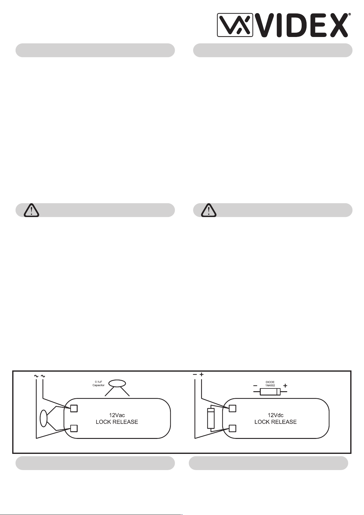
Fig.1A Fig.1B
LOCK RELEASE BACK EMF PROTECTION
A capacitor must be fitted across the terminals on AC lock release
(Fig.1A) and a diode must be fitted across the terminals on a DC lock
release (Fig.1B) to suppress back EMF voltages. Connect this
components to the lock releases asshownin figures.
AZIONAMENTO SERRATURA- PROTEZIONE DAI DISTURBI
L’azionamento della serratura elettrica può provocare degli spike,per
evitare tale inconveniente si consiglia di collegare tra i terminali della
serratura un condensatore (Fig.1A) o un diodo (Fig.1B) a seconda
che la serraturasia in alternata o incontinua.
Page 2
INSTALLING OUTDOOR STATIONINSTALLAZIONE POSTO ESTERNO
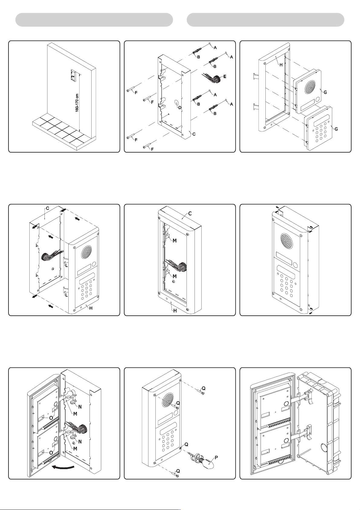
Fig.1 Fig.2 Fig.3
Fig.4 Fig.5 Fig.6
Fig.7 Fig.8 Fig.9
Page 3

INSTALLING OUTDOOR STATION INSTALLAZIONE POSTO ESTERNO
SURFACEDOOR STATION (DK4K-1S)
!
Place the surface box against the wall (165-170cm between
the top of the boxand the floor level as shown in figure 1) and
mark the fixing holes for the wall plugs and the hole for the
cables (fig.2). Observe the orientation of the box with the
hinge on the left;
!
As shown on figure 2, drill the fixing holes , insert the wall
plugs and feed the cables through the surface box
opening , fix surface box tothe wall using the screws ;
!
Before the installation of the module support frame, hook the
modules to thesupport frame as shown infigure 3;
!
As shown in figure 4, hook the module support frame
(complete with modules) to the surface box moving the
frame as suggested from pointers. Ensure that the pivots
(fig.4) go inside the relevant housing as shown in figure 5.
!
As shown on figure 6, pull back the module support frame
while moving it slightly to the left as suggested by the
pointers;
!
As shown in figure 7, open the module support frame as
suggested by the pointer, hook the hinge locks to the
hinges , make the required connections using the
screwdriver (Ref. figure 8) provided (blade flat side) and
make the required adjustment by adjusting the settings
(through openings ) and adjust trimmers;
!
When the system has been tested and is working correctly,
move back the module support frames carefully, fix them to
the surface box using the screwdriver provided (blade torx
side) and the pin machine torx screws as shown on figure
8.
necessary.
E
A
BE
DC F
GH
C
M
H
N
M
P
O
P
Q
Note: do not overtighten the screws more than is
POSTO ESTERNO DA SUPERFICIE (DK4K-1S)
!
Appoggiare la scatola da superficie alla parete (ci devono
essere 165-170cm tra la parte alta della scatola e il terreno
come mostrato in fig.1) e prendere i riferimenti per i fori di
fissaggio tenendo contro che il gruppo di fili (fig.2) deve
attraversare il foro (fig.2) della scatola da superficie. Se
D
non indicato, il verso della scatola deve essere tale da
lasciare la cerniera a sinistra;
!
Come mostrato in figura 2, realizzare i fori di fissaggio ,
inserire all’interno deifori glistop e,facendo passarei cavi
di collegamento attraverso il foro , fissare la scatola da
H
L
H
superficie alla parete utilizzando le viti ;
!
Applicare ad incastro i moduli al supporto come mostrato
in figura 3.
!
Come mostrato in figura 4, agganciare il supporto moduli
(completo di moduli) alla scatola da superficie ,
ED
CF
B
GH
muovendolo come suggerito dalle frecce. Fare attenzione
che i perni (fig.4) si inseriscano nel relativo alloggiamento
come mostrato in figura 5;
M
!
Come mostrato in figura 6, tirare il supporto moduli indietro
L
compiendo contemporaneamente un leggero movimento a
sinistra come suggerito dalle frecce;
!
Come mostrato in figura 7, ruotare il supporto moduli come
suggerito dalla freccia, agganciare i fermi delle cerniere
agli alloggiamenti , collegare i fili utilizzando il cacciavite
(lato piatto) fornito a corredo (Rif. fig.8) ed eseguire le
M
P
opportune regolazioni dei moduli agendo attraverso i fori dei
trimmer o le fessure ;
!
Quando il sistema è stato testato ed è funzionante,
O
procedendo a ritroso delicatamente, chiudere e fissare il
supporto alla scatola da superficie utilizzando il cacciavite
(lato torx) ele viti fornite a corredo come mostratoin figura
8.
Nota bene: non serrare le viti più del necessario.
Q
E
N
A
H
C
H
H
P
FLUSH DOOR STATION (DK4K-1)
!
Protect the module support frame fixing holes from dust then
embed the back box into the wall (165-170cm between the
top of the box and the floor level as shown on the figure 1)
feeding the cables (fig.2) through a previous open hole in
the box. Observe the direction of the box ensuring the hinge
is on the left and take care that the box profile must be in line
with the finished wall profile;
!
Continue from the third step of surface mounting, but at the
sixth step hook the hinge locks as shown on figure9.
Notes
The screwdriver’s blade has two sides, one flat and one torx, to
select one of them unplug the blade from the screwdriver body
and plug it into the required side.
E
N
POSTO ESTERNO DA INCASSO (DK4K-1)
Dopo aver opportunamente protetto i fori di fissaggio del
supporto moduli, murare la scatola da incasso (lasciare 165170cm tra la parte alta della scatola e il terreno) facendo
passare il gruppo di fili e (fig.2) attraverso uno dei fori
(precedentemente aperto) sul fondo della scatola. Se non
indicato sul fondo della scatola, il verso deve essere tale da far
rimanere la cerniera a sinistra. Fate attenzione affinché la
scatola venga murata a filo muro finito;
Continuare dal terzo dell’installazione da superficie, ma al
sesto agganciare i fermi delle cerniere n come mostrato in
figura 9.
Note
La lama del cacciavite fornito a corredo ha due punte, una
piatta ed una torx. Sfilare la punta e reinserirla nel manico
scegliendo il lato desiderato.
Page 4

We recommend
This equipment is installed
by a Competent Electrician,
Security or Communications
Engineer
Factory - Office
VIDEX ELECTRONICS S.p.A
Phone: (+39) 0734 - 631669 Fax: (+39) 0734 - 632475 www.videx.it e-mail: info@videx.it
Northern UK Office
VIDEX LTD
Phone: 0191 2243174 Fax: 0191 - 2241559 www.videx-security.com
(All Countries Support)
. Via del lavoro,1 63020 MONTEGIBERTO (AP) - ITALY
Unit 5-7 Chillingam Industrial Estate Chapman Street NEWCASTLE UPON TYNE Ne6 2XX
(Only UK Support)
66250360.cdr 15/02/07
Page 5

Digital Codelock Unit Module
Art.4800
INSTALLATION INSTRUCTION
CODELOCK UNIT MODULES MODULI TASTIERA DIGITALE
Art.4800
This module has on the front a 12 stainless steel button
keypad (keys from “0”to“9” plus “ENTER” and “CLEAR”
keys), 2 LEDS for operation signalling, the keypad
illumination LEDs and a mirror stainless steel front plate
(standard version). Codelock unit module has 3 built-in
relays that allow to enable up to 3 services (door-open,
gate-open etc.) by typing the programmed secret codes.
Acoustic and visual (green and red front LEDs) signals
facilitate the use and the programming operations. This
module can be used individually or combined with other
modules on an audio or video door entry systems.
MAIN FEATURES CARATTERISTICHE PRINCIPALI
- 3 C, NC, NO relay outputs (24Vac/dc – 5A max);
- 3 Programmable secret codes (one for each relay);
- Each relay can be set to be activated for a specific time (01 to 99
seconds) or to work as latch;
- Two active low inputs to command directly the relay 1 and 2;
- Programming menu guarded by a 4-8 digit programmable engineer’s
code;
- Visual and Acoustic signal during operating and programming;
- Keypad illumination LEDs;
Modulo Tastiera digitale
Art.4800
- 3 relé con contatti C, NC, NO (24Vac/dc – 5A max);
- 3 Codici programmabili (uno per ogni relé);
- Ciascun relé può essere programmato per l’attivazione temporanea
(01..99 secondi) o per il funzionamento a commutazione;
- 2 Ingressi (attivo basso) per comandare direttamente i relé1e2;
- Menù di programmazione protetto da un codice segreto programmabile;
- Segnali acustici e visivi durante il funzionamento;
- LED di illuminazione tastiera
ISTRUZIONI D’INSTALLAZIONE
Art.4800
Questo modulo presenta nella parte frontale una tastiera a
12 pulsanti (tasti da “0”a“9” più i tasti “ENTER” e
“CLEAR”) in acciaio inossidabile, 2 LED per le indicazioni
di funzionamento ed i LED d’illuminazione tastiera; il tutto
è protetto da una placca frontale in acciaio inossidabile
lucidato a specchio (versione standard). L’unità è
equipaggiata con 3 relé attraverso i quali è possibile
abilitare altrettanti servizi (apertura porta, apertura
cancello ecc.) digitando il relativo codice segreto. Segnali
acustici e visivi (LED frontali rosso e verde) facilitano le
operazioni di utilizzo e programmazione. Il modulo può
essere impiegato singolarmente o in abbinamento ad altri
moduli in sistemi citofonici/videocitofonici
GENERAL DIRECTIONS FOR INSTALLATION NORME GENERALI D’INSTALLAZIONE
In order to achieve the best results from the schematics described it is
necessary to install only original VIDEX equipment, strictly keeping to the
items indicated on each schematic and follow these General Directions for
Installation:
- The system must be installed according to national rules in force, in any
case the running of cables of any intercom unit must be carried out
separately from the mains;
- All multipair cables should be compliant to CW1308 specification
(0.5mm twisted pair telephone cable).
- Cables for speech line and service should have a max resistance of 10
Ohm
- Lock release wires should be doubled up (Lock release wires and
power supply wires should have a max resistance of 3 Ohm);
- The cable sizes above can be used for distances up to 50m. On
distances above 50m the cable sizes should be increased to keep the
overall resistance of the cable below the RESISTANCES indicated
above;
- Double check the connections before power up;
- Power up the system then check all functions.
Lock Release Back EMF Protection
A capacitor must be fitted across the terminals on AC lock release
(Fig.1A) and a diode must be fitted across the terminals on a DC lock
release (Fig.1B) to suppress back EMF voltages.
Connect the components to the lock releases as shown in figures.
Per eseguire una corretta installazione è necessario impiegare
esclusivamente parti VIDEX, seguire con scrupolo quanto indicato negli
schemi di collegamento e tenere presenti le norme generali
d’installazione:
- Realizzare gli impianti secondo le vigenti normative nazionali ed in ogni
caso si consiglia di prevedere, per i conduttori dell’impianto, una
canalizzazione distinta da quella della linea elettrica (vedi paragrafo
seguente per il collegamento alla linea elettrica e l’installazione
dell’alimentatore);
- Impiegare conduttori con sezioni tali da avere:
• resistenza complessiva inferiore a 10 Ohm per quelli della linea fonica
e di comando;
•resistenzacomplessivainferiorea3Ohmperquelli della serratura e
di alimentazione;
- Verificare le connessioni prima di dare alimentazione all'impianto;
- Alimentare l’impianto ed eseguire il collaudo verificandone tutte le
funzioni
Azionamento Serratura – Protezione dai Disturbi
L’azionamento della serratura elettrica può provocare degli spike, per
evitare tale inconveniente si consiglia di collegare tra i terminali della
serratura un condensatore (Fig.1A) o un diodo (Fig.1B) a seconda che la
serratura sia in alternata o in continua.
Buzzer Back EMF
When using intercoms with buzzer call (Art.924/926, SMART1/2, 3101/2,
3001/2 and 3021/2) add one 0,1uF capacitor between terminals 6 and 3.
PrtCode:66250070 21/12/2006 Rev.1.2
Buzzer Protezione dai Disturbi
Utilizzando citofoni con chiamata su buzzer (Art.924/926, SMART1/2,
3101/2, 3001/2 e 3021/2) inserire un condensatore da 0,1uF tra i morsetti
6e3.
Page 6

PROGRAMMING (SEE ALSO THE RELEVANT FLOW CHART) PROGRAMMAZIONE (VEDI RELATIVO DIAGRAMMA DI FLUSSO)
- Enter the “ENGINEER’S CODE”: first time type six times “1” (111111
factory preset) and press “ENTER” (The red LED will illuminate);
- Confirm “ENGINEER’S CODE” (typing again the same) or type the new
code (4 to 8 digits) then press “ENTER” (Melody). Pressing twice the
“ENTER” button without changing the “ENGINEER’S CODE”, will exit
from the programming;
- Enter the code (4 to 8 digits) to enable “RELAY 1” or re-enter the
existing code then press “ENTER” (Melody);
- Enter the “RELAY 1” operation time (2 digits 01 to 99 I.E. 05=5
seconds, 00= remain open time) or re-enter the existing time then press
“ENTER” (Melody);
- Enter the code (4 to 8 digits) to enable “RELAY 2” or re-enter the
existing code then press “ENTER” (Melody);
- Enter the “RELAY 2” operation time (2 digits 01 to 99 I.E. 05=5
seconds, 00= remain open time) or re-enter the existing time then press
“ENTER” (Melody);
- Enter the code (4 to 8 digits) to enable “RELAY 3” or re-enter the
existing code then press “ENTER” (Melody);
- Enter the “RELAY 3” operation time (2 digits 01 to 99 I.E. 05=5
seconds, 00= remain open time) or re-enter the existing time then press
“ENTER” (Melody);
- The system is ready to use (the red LED will be off).
- Digitare il “MASTER CODE”: 6 volte “1” (111111 imp ost azione di
fabbrica) e premere “ENTER” (il LED rosso si accende);
- Confermare il “MASTER CODE” (digitandolo nuovamente) o digitarne
uno nuovo (da 4 ad 8 cifre) quindi premere “ENTER” (segnale
acustico). Premendo due volte “ENTER” senza modificare il “MASTER
CODE” si esce dalla programmazione;
- Digitareilcodicediattivazione(da4ad8cifre)del“RELÈ1”quindi
premere “ENTER” (segnale acustico);
- Digitare il tempo di funzionamento del “RELÈ 1” (2 cifre da 01 a 99
Es.05=5 secondi 00=Commutazione di stato) quindi premere “ENTER”
(segnale acustico);
- Digitareilcodicediattivazione(da4ad8cifre)del“RELÈ2”quindi
premere “ENTER” (segnale acustico);
- Digitare il tempo di funzionamento del “RELÈ 2” quindi premere
“ENTER” (segnale acustico);
- Digitare il codice di attivazione (da 4 ad 8 cifre) del “RELÈ 3” quindi
premere “ENTER” (segnale acustico);
- Digitare il tempo di funzionamento del “RELÈ 3” quindi premere
“ENTER” (segnale acustico);
- Il sistema è pronto all’uso (il LED rosso si spegne).
Programming Notes
- After the confirmation of an entered data by pressing the “ENTER”
button, by pressing twice the same button you can exit from the
programming.
RETURN SYSTEM TO PRESET ENGINEER’S FACTORY CODE
- Turn off power to code lock;
- Keep “ENTER” button pressed while turning back on the power;
- Release “ENTER” button;
- The engineer’s code is now set at “111111 ” (six times one).
CODELOCK UNIT PROGRAMMING FLOW-CHART FLOW-CHART DI PROGRAMMAZIONE TASTIERA DIGITALE
Note di Programmazione
- Dopo aver confermato l’inserimento di un dato premendo il tasto
“ENTER”, premendolo nuovamente per due volte consecutive, si esce
dalla programmazione.
RIPORTARE L’UNITÀ ALLE IMPOSTAZIONI DI FABBRICA
- Togliere l’alimentazione alla tastiera;
- Tenendo premuto il tasto “ENTER”, dare nuovamente alimentazione;
- Rilasciare il tasto “ENTER”;
- Il codice master è nuovamente impostato a “111111” (sei volte uno).
OPERATION FUNZIONAMENTO
- Type in the programmed code and press “ENTER”;
- If the code is right, the green LED will illuminate (about 2s) and the relay
relevant to the code will operate for the programmed time;
- If a wrong code is entered, a continuous melody will sound for 4 or more
seconds, according to the number of mistakes;
- To switch off any relay while operating, type in the relevant code then
press the “CLEAR” button;
Operation Notes
- To operate relays together, set the same code for each relay;
- If a wrong code is entered, the system will lock out for 5 seconds which
will increase each time a wrong code is entered. The system will
operate only when the correct code is entered.
PrtCode:66250070 21/12/2006 Rev.1.2
- Digitare il codice segreto e premere “ENTER”;
- Se il codice è corretto, il LED verde si accende (2s circa) ed il relé
relativo al codice si attiva per il tempo programmato;
- Se il codice è errato, una melodia losegnala per 4 secondi o più in base
al numero di digitazioni errate;
- Per disattivare uno dei relé mentre è in funzione, digitare il relativo
codice quindi premere il tasto “CLEAR”.
Note di Funzionamento
- Per far funzionare i relé contemporaneamente, impostare lo stesso
codice d’attivazione per ciascun relé.
- Se viene digitato un codice errato, l’unità si blocca per 5 secondi: il
tempo di blocco aumenta in base al numero di errati inserimenti. L’unità
funzionerà solo digitando un codice corretto.
Page 7

TERMINALS:
SW2
SW1
NC3
NO3
C3
NC2
NO2
C2
NC1
NO1
C1
+
Relay 2 command signal (active low)
Relay 1 command signal (active low)
Relay 3 normally closed contact
Relay 3 normally open contact
Relay 3 common contact
Relay 2 normally closed contact
Relay 2 normally open contact
Relay 2 common contact
Relay 1 normally closed contact
Relay 1 normally open contact
Relay 1 common contact
12/24Vac/dc power input
MORSETTIERA:
SW2 Comando d’abilitazione del relé 2 (ingresso attivo basso)
SW1 Comando d’abilitazione del relé 1 (ingresso attivo basso)
NC3 Relé 3 contatto normalmente chiuso
NO3 Relé 3 contatto normalmente aperto
C3 Relé 3 contatto comune
NC2 Relé 2 contatto normalmente chiuso
NO2 Relé 2 contatto normalmente aperto
C2 Relé 2 contatto comune
NC1 Relé 1 contatto normalmente chiuso
NO1 Relé 1 contatto normalmente aperto
C1 Relé 1 contatto comune
+
Ingresso d’alimentazione 12/24Vac/dc
TECHNICAL SPECIFICATION
Power Supply: 12/24 Vac/dc – 2VA
Power Consumption: 50mA max
Working Temperature: -10 +50 C
INSTALLATION DIAGRAMS SCHEMI DI INSTALLAZIONE
SPECIFICHE TECNICHE
Tensione d’alimentazione: 12/24 Vac/dc - 2VA
Assorbimento: 50mA max
Temperatura di lavoro: -10 +50 C
PrtCode:66250070 21/12/2006 Rev.1.2
Page 8

CUSTOMER SUPPORT INFORMATION INFORMAZIONI ASSISTENZA CLIENTI
All Countries Customers UK Customers Clienti di tutti i Paesi Clienti UK
VIDEX Electronics S.p.A.
www.videx.it
– technical@videx.it
Tel.+39 0734 631669
Fax +39 0734 632475
The product is CE marked demonstrating its conformity and is for distribution within all
member states of the EU with no restrictions.
This product follows the provisions of the European Directives
89/336/EEC & 92/31/EEC (EMC),
73/23/EEC (LVD) and 93/68/EEC (CE marking).
VIDEX Security LTD
www.videx-security.com
Tech Line 0191 224 3174
Fax 0191 224 1559
VIDEX Electronics S.p.A.
www.videx.it
– technical@videx.it
Tel.+39 0734 631669
Fax +39 0734 632475
Il prodotto è marchiato CE a dimostrazione della sua conformità e può essere distribuito
liberamente all’interno dei paesi membri dell’unione europea EU.
Questo prodotto è conforme alle direttive Europee
89/336/EEC & 92/31/EEC (EMC),
73/23/EEC (LVD) e 93/68/EEC (Marcatura CE).
VIDEX Security LTD
www.videx-security.com
Tech Line 0191 224 3174
Fax 0191 224 1559
PrtCode:66250070 21/12/2006 Rev.1.2
 Loading...