

Page 1
TECHNICAL MANUAL
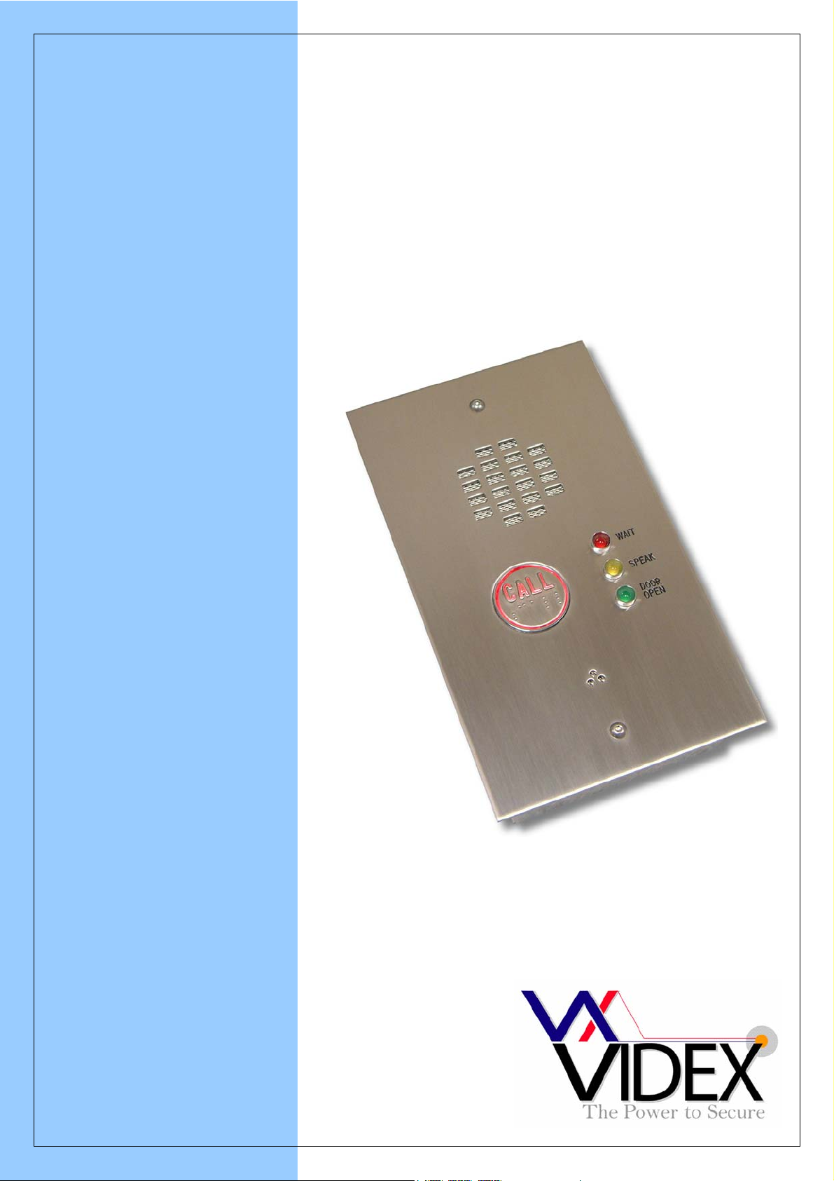
One button DDA audio intercom kit
25H/DDA
TECHNICAL MANUAL
EDITION 1.1
Page 2
INTRODUCTION
The door entry kit has the following features:
• Electronic call tone - Upon a call being initiated, the telephone will attract the attention of the occupant
with up to ten warbled rings.
• Timed door release - Upon pressing the door release button on the telephone, a dry contact relay within
the door panel will energise for 5 seconds.
• Visual indication of call progress on the door panel – In standby, the door panel call button will be
illuminated awaiting being pressed. Upon pressing the button, the illumination will begin to flash and
during the conversation and door release the button illumination will be off. Additionally three LED’s
indicate when the telephone is ringing (Red LED), when to speak (Yellow LED), and when the door is
open (Green LED).
• Call tone volume adjust – The volume can be adjusted using a three position volume control located on
the telephone.
COMPONENTS
The standard components of the kit are as follows:
• Door panel (VR1N/DDA) - A one button vandal resistant flush fitting door panel with large
illuminated call button with raised letters and Braille.
• Audio telephone (3111) – A white ABS plastic wall mountable telephone with three position
call tone volume adjust, door release button and spare service button.
• Power supply (521) – A 13.5Vdc DIN rail or wall mountable power supply unit capable of
supplying up to 800mA continuous or 1A surge.
CONNECTIONS
DOOR PANEL
AMPLIFIER
1 Receive speech from telephone (12Vdc on hook, 4Vdc off hook)
2 Transmit speech to telephone (12Vdc on hook, 1Vdc off hook)
3 Positive supply to amplifier (12Vdc)
4 Negative (0V) supply to amplifier
BUTTON
SW Normally open switch
SW Other side of normally open switch
LAMP One side of button illumination +12Vdc
LAMP Other side of button illumination (Switched 0V)
CONTROL PCB
5 Door release from telephone (Switched negative from 5Vdc)
4 Call tone out to telephone
Tr Trigger from call button to initiate a call (Triggers on 12Vdc)
2 Handset lift detect line (12Vdc on hook, 1Vdc off hook)
Gnd 0V from power supply
+12 12Vdc from power supply
CO Common connection of dry contact lock relay
NO Normally open connection of dry contact relay
NC Normally closed connection of dry contact relay
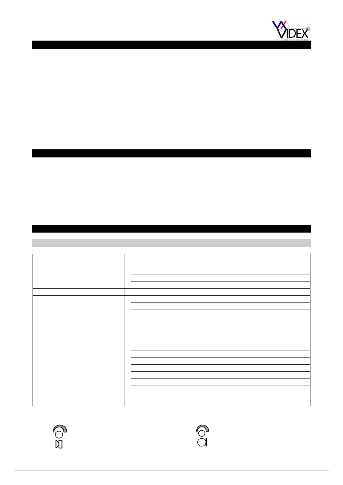
Speech volume adjustments are carried out at the door panel using a small trimmer driver.
Adjustment for speech
volume level at the door
station
Adjustment for speech
volume at the apartment
PAGE 2 25H/DDA TECHNICAL MANUAL VER1.1
Page 3
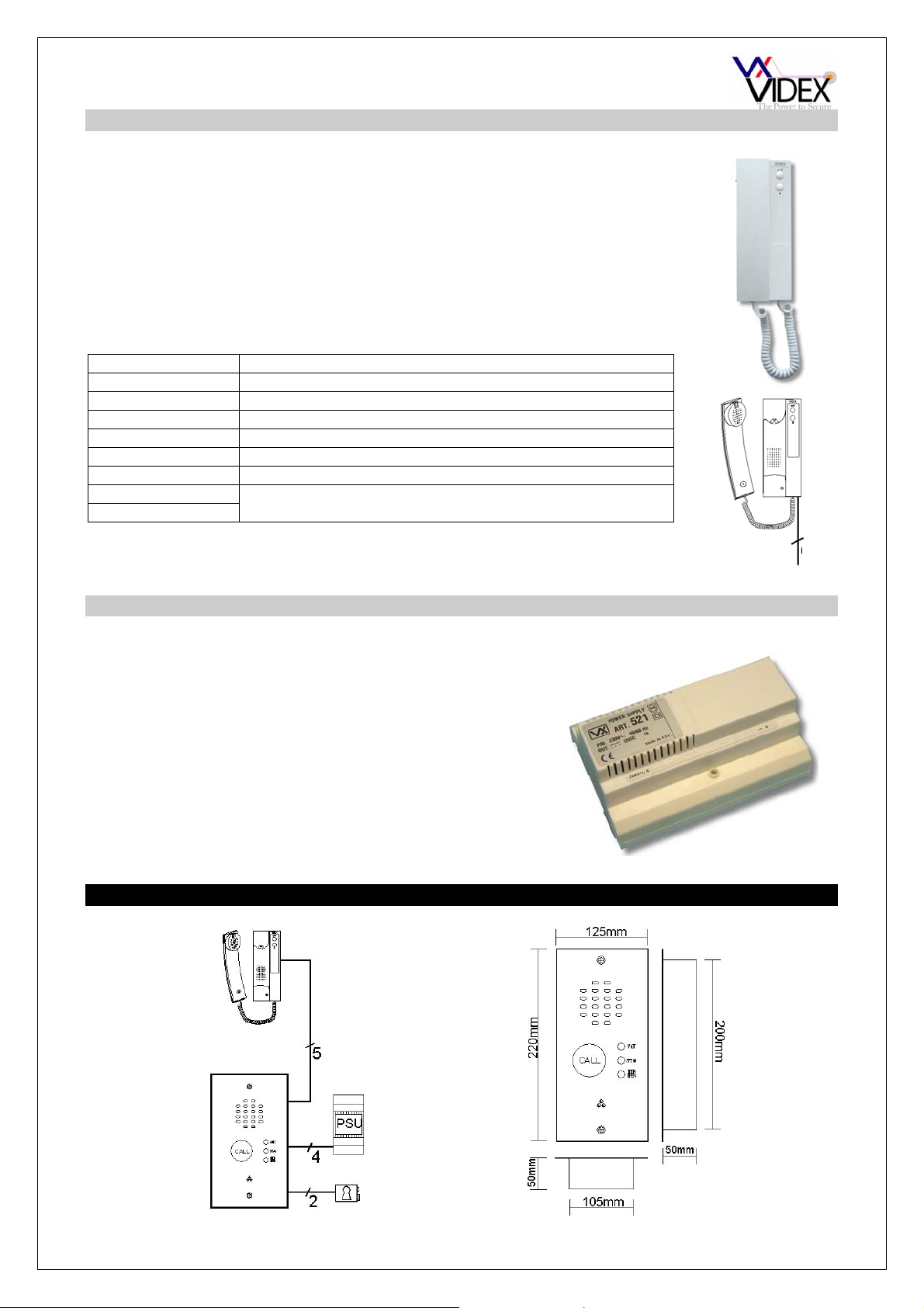
TELEPHONE
Art.3111
The Art.3111 includes a three position call tone volume control, lock release push
button and spare dry contact push to make button for other services. Up to three
telephones can be connected in parallel on this system.
CONNECTIONS: Function
4 Call tone in from door panel
6 Not used on this system
2 Receive speech from the door panel
1 Transmit speech to the door panel
3 0V
5 Switch 0V lock trigger command
8 Dry contact switch
9
POWER SUPPLY
Art.521
The 521 PSU can supply 800mA constant or a 1A surge. The
output is 13.5Vdc and is protected by a fall back circuit (No
internal fuses on either the primary or secondary of the PSU. A
fused spur should always be used with this type of PSU).
BLOCK DIAGRAM AND DOOR PANEL DIMENSIONS
PAGE 3 25H/DDA TECHNICAL MANUAL VER1.1
5
Page 4

INSTALLATION
The wiring diagram towards the back of this manual should be followed carefully. Heavy duty conductors on
wiring diagrams are shown heavily outlined, These wires should be doubled up.
- Check that all components are free from damage before installing (Do not proceed with installation in the
event of damage).
- Keep all packaging away from children.
- Do not obstruct the ventilation openings or slots on any of the devices.
- All connections to mains voltages must be made to the current national standards (IEE Wiring
regulations)
- Install an appropriate fused spur or isolation switch to isolate the mains.
- Isolate the mains before carrying out any maintenance work on the system.
- All intercom and access control cables must be routed separately from the mains.
Lock release protection : A diode must be fitted across the terminals on the lock release to suppress back
EMF voltages. The diagram below shows the polarity of the diode when fitted to the release.
-
+
-
DIODE
1N4002
+
12V DC
LOCK RELEASE
Cable size and type : When running cables for any intercom system, these cables must be installed
separately from the mains cables. All multipair cables should be to CW1308 specification. (0.5mm twisted
pair telephone cable). Max resistance = 10 Ohm.
Lock release wires should be doubled up. Max resistance = 3 Ohm
The cables sizes above can be used for distances up to 100m. On distances above 100m the cable sizes
should be increased to keep the overall resistance of the cable below the RESISTANCES indicated above.
TESTING THE INSTALLATION
- Check all the connections have been made correctly and then power up the system.
- Call the apartment. Check for call tone to the apartment, speech in both directions and lock release.
- If the volume of speech needs to be adjusted, this can be done by adjusting the presets on the rear of
the amplifier at the door panel as shown earlier in this manual.
- If the call tone volume needs adjusting this can be done at each handset (Three position slide switch on
the telephone).
PAGE 4 25H/DDA TECHNICAL MANUAL VER1.1
Page 5
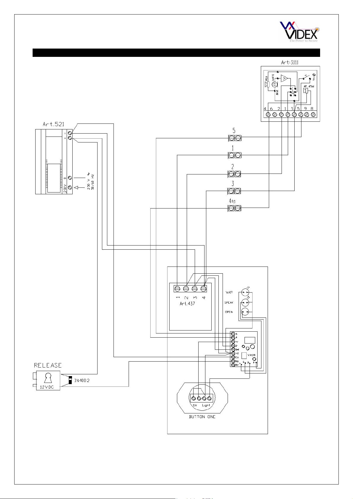
WIRING DIAGRAM
PAGE 5 25H/DDA TECHNICAL MANUAL VER1.1
Page 6

USER INSTRUCTION
PAGE 6 25H/DDA TECHNICAL MANUAL VER1.1
Page 7
TROUBLE SHOOTING
SYMPTOM TEST
No speech from door panel Check terminal 2 on the door amplifier PCB for
continuity back to terminal 2 on the telephone
Check for 12V on terminal 2 of the door amplifier
(Use terminal 4 as the ground). Check this with and
without a wire connected to terminal 2 to eliminate a
short of on the wire.
Check the voltage drops to approx. 1Vdc when the
handset is lifted. (If not try another telephone)
If all else fails try another amplifier at the door station
No speech from handset Check terminal 1 on the amplifier for continuity back
to the terminal 1 on the telephone
Check for 12V on terminal 1 of the door amplifier
(Use terminal 4 as the ground). Check this with and
without a wire connected to terminal 1 to eliminate a
short of on the wire.
Check the voltage drops to approx. 4Vdc when the
handset is lifted. (If not try another telephone)
If all else fails try another amplifier at the door station
Phone does not stop ring when handset is lifted. Check terminal 2 on handset for continuity back to
the door panel VX128 control PCB’s terminal 2.
Lock will not operate from telephone Check terminal 5 on the telephone for continuity
back to terminal 5 on the door panel VX128 control
PCB.
Check the voltage on terminal 5 of the handset. 5Vdc
in standby dropping to 0V when the release button is
pressed.
Lock operates as soon as the handset is lifted. Check for shorts across terminal 5 of the telephones
and other cables.
Check terminal 5 voltage. Should be 5Vdc when the
button is not being pressed.
Nothing happens when call button is pressed Check power to the VX128 PCB in the door panel.
Should be 12Vdc.
Check the connections on the call button.
No call tone to telephone but speech and lock ok
when handset is lifted
Hum on the speech lines Ensure all intercom cables do not run close to higher
Try another amplifier at the door panel.
Check terminal 4 on the telephone for continuity
back to terminal 4 on the VX128 PCB in the door
panel.
voltage cables
PAGE 7 25H/DDA TECHNICAL MANUAL VER1.1
Page 8

Northern Office
Videx Security Ltd
Unit 4-7 Chillingham Ind. Est.
Newcastle Upon Tyne
NE6 2XX
TEL 0870 300 1240
FAX 0191 224 5678
Southern Office
1 Osprey
Trinity Park
Trinity Way
London
E4 8TD
FAX 0208 523 5825
TECHNICAL SUPPORT
tech@videx-security.com
TEL 0191 224 3174
FAX 0191 224 4938
http://www.videx-security.com
SALES SUPPORT
sales@videx-security.com
TEL 0870 300 1240
FAX 0191 224 5678
PAGE 8 25H/DDA TECHNICAL MANUAL VER1.1
 Loading...