

Page 1
INSTALLING A 4 MODULES OUTDOOR STATION
Fig.1 Fig.2 Fig.3
INSTALLAZIONE POSTO ESTERNO A 4 MODULI
Fig.4 Fig.5 Fig.6
Fig.7 Fig.8 Fig.9
Fig.10 Fig.11 Fig.12
25
Page 2
INSTALLING SURFACE MOUNTING DOOR STATION INSTALLAZIONE POSTO ESTERNO DA SUPERFICIE
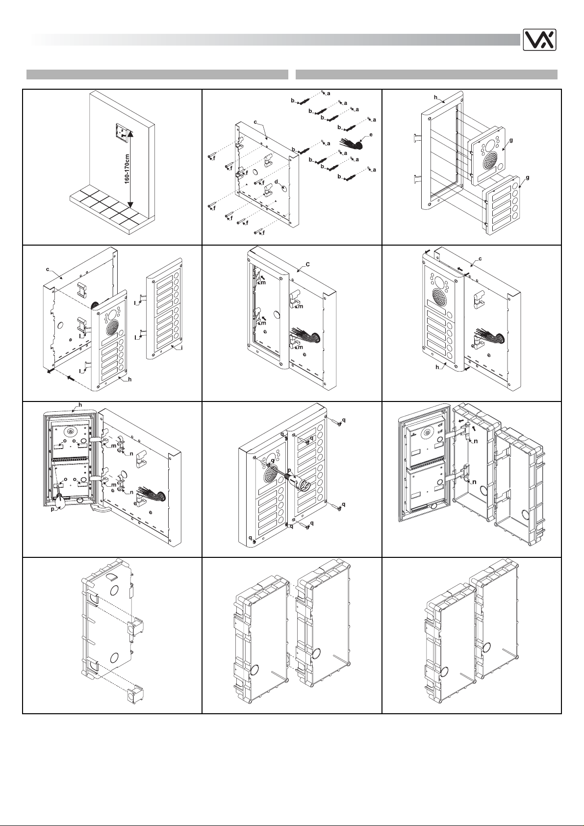
1. Place the surface box against the wall (165-170cm between the top
of the box and the floor level as shown in figure 1) and mark the
fixing holes for the wall plugs and the hole for the cables e (fig.2).
Observe the orientation of the box with the hinge on the left;
2. As shown on figure 2, drill the fixing holes a, insert the wall plugs b
and feed the cables e through the surface box opening d, fix surface
box c to the wall using the screws f;
3. Before the installation of the module support frame, hook the
modules g to the support frame h as shown in figure 3 (do the same
for the second module support frame);
4. When you have more than one support frame, hook the support
frame to the surface box starting from the left. For convenience, we
will described how to attach operate on left frame but naturally the
same must be done on the right frame. As shown in figure 4, hook
the module support frame h (complete with modules) to the surface
box c moving the frame as suggested from point ers. Ensure that the
pivots l (fig.4) go inside the relevant housing m as shown in figure 5.
5. As shown on figure 6, pull back the module support frame h while
moving it slightly to the left as suggested by the pointers;
6. As shown in figure 7, open the module support frame h as suggested
by the pointer, hook the hinge locks n to the hinges m, make the
required connections using the screwdriver provided p (blade flat
side) and make the required adjustment by adjusting the settings
(through openings o) and adjust trimmers;
7. Repeat the same operations described above for the second module
support frame;
8. When the system has been tested and is working correctly, move
back the module support frames carefully, fix them to the surface box
using the screwdriver provided p (blade torx side) and the pin
machine torx screws q. Note: do not overtighten the screws more
than is necessary.
INSTALLING FLUSH MOUNTING DOOR STATION INSTALLAZIONE POSTO ESTERNO DA INCASSO
In case of flush mounting where the number of modules is greather than 3,
the required back boxes need to be linked together (before embed them in
the wall) as shown on figures 10,11 and 12:
- Arrange back boxes and remove knockouts to allow cables to be fed
from one back box to the other.
- Hook the spacers to first back box then hook the second back box to
get the result shown on figure 12.
1. Protect the module support frame fixing holes from dust then embed
the back box into the wall (165-170cm between the top of the box
and the floor level as shown on the figure 1) feeding the cables e
(fig.2) through a previous open hole in the box. Observe the direction
of the box ensuring the hinge is on the left and take care that the box
profile must be in line with the finished wall profile;
2. Continue from step 3 of surface mounting, but at step 6 hook the
hinge locks n as shown on figure 9.
Notes
- The screwdriver’s blade has two sides, one flat and one torx, to select
one of them unplug the blade from the screwdriver body and plug it into
the required side.
- The example shows the use of only one back box bottom hole for wires,
this is done to keep the drawings clear. Naturally the installer can use
the left hole or the right or both if required.
1. Appoggiare la scatola da incasso alla parete (ci devono essere 165170cm tra la parte alta della scatola e il terreno come mostrato in
fig.1) e prendere i riferimenti per i fori di fissaggio tenendo contro che
il gruppo di fili e (fig.2) deve attraversare il foro d (fig.2) della scatola
da superficie. Se non indicato, il verso della scatola deve essere tale
da lasciare la cerniera a sinistra;
2. Come mostrato in figura 2, realizzare i fori di fissaggio a, inserire
all’interno dei fori gli stop b e, facendo passare i cavi di collegamento
e attraverso il foro d, fissare la scatola da superficie c alla parete
utilizzando le viti f;
3. Prima di installare il supporto moduli, agganciare a quest’ultimo i
moduli g come mostrato in figura 3 (eseguire la stessa operazione
per il secondo supporto moduli);
4. Quando sono necessari più di un supporto moduli, questi vanno
agganciati alla scatola da superficie partendo da quello più a sinistra.
Per praticità verrà descritto come procedere con il supporto di
sinistra, ma naturalmente le stesse operazioni valgono anche per
quello di destra. Come mostrato in figura 4, agganciare il supporto
moduli h (completo di moduli) alla scatola da superficie c,
muovendolo come suggerito dalle frecce. Fare attenzione che i perni
l (fig.4) si inseriscano nel relativo alloggiamento m come mostrato in
figura 5;
5. Come mostrato in figura 6, tirare il supporto moduli h indietro
compiendo contemporaneamente un leggero movimento a sinistra
come suggerito dalle frecce;
6. Come mostrato in figura 7, aprire il supporto moduli h come suggerito
dalla freccia, agganciare i fermi n delle cerniere agli alloggiamenti m,
collegare i fili utilizzando il cacciavite fornito (lato piatto) a corredo ed
agire sulle fessure o dei moduli o sui fori dei trimmer per le opportune
regolazioni;
7. Compiere le stesse operazioni sopra descritte anche per il supporto
secondo supporto moduli;
8. Quando il sistema è stato testato ed è funzionante, procedendo a
ritroso delicatamente, chiudere e fissare i supporti alle scatole da
superficie utilizzando il cacciavite p (lato torx) e le viti q fornite a
corredo. Nota bene: non serrare le viti più del necessario
Se l’installazione è da incasso e il posto esterno è composto da più di 3
moduli, occorre collegare le scatole da incasso (prima di murarle) come
mostrato nelle figure 10,11 e 12:
- Preparare le scatole da incasso aprendo le finestre in corrispondenza
degli alloggiamenti per i distanziali dal lato in cui questi verranno
agganciati;
- Inserire i distanziali nella prima scatola da incasso quindi agganciare la
seconda ad ottenere il risultato di figura 12.
1. Dopo aver opportunamente protetto i fori di fissaggio del supporto
moduli, murare la scatola da incasso (lasciare 165-170cm tra la parte
alta della scatola e il terreno) facendo passare il gruppo di fili e (fig.2)
attraverso uno dei fori (precedentemente aperto) sul fondo della
scatola. Se non indicato sul fondo della scatola, il verso deve essere
tale da far rimanere la cerniera a sinistra. Fate attenzione affinché la
scatola venga murata a filo muro finito;
2. Continuare dal passo 3 dell’installazione da superficie, ma al passo 6
agganciare i fermi delle cerniere n come mostrato in figura 9.
Note
- La lama del cacciavite fornito a corredo ha due punte, una piatta ed una
torx. Sfilare la punta e reinserirla nel manico scegliendo il lato
desiderato.
- L’esempio mostra l’utilizzo di un solo foro della sca tola da superficie per
il passaggio dei fili, questo è stato fatto solo per praticità e per rendere
più puliti i disegni. Naturalmente l’installatore può utilizzare a suo
piacimento il foro di destra, quello di sinistra o entrambi per il passaggio
dei fili
.
26
 Loading...