

Page 1
Audio
Installation Instructions
8K/380
Kit
Istruzioni di Installazione
Fig.1A Fig.1B
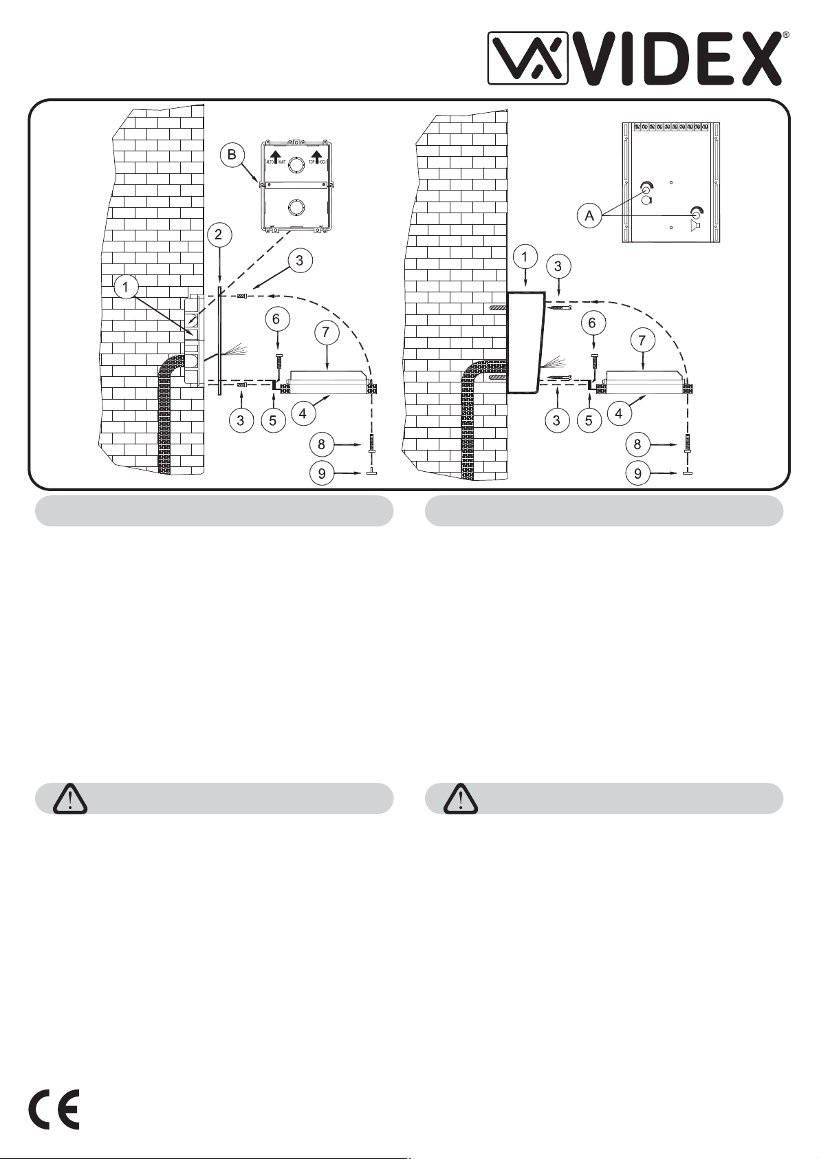
ISTRUZIONI DI MONTAGGIO DEL POSTO ESTERNO
POSTO ESTERNO DA INCASSO (Fig.1A)
!
Installare il citofono Art.3011 a parete utilizzando le viti ed i relativi tasselli ad espansione forniti a
corredo;
!
Installare il trasformatore Art.321 su barra DIN o direttamente a parete utilizzando le viti ed i relativi
tasselli adespansione fornitia corredo (vedi paragrafosuccessivo);
!
Murare lascatola daincasso ( ) all'altezza desiderata rispettandoil verso della freccia ( );
!
Rifinire accuratamentela muraturae liberare tutti ifori difissaggio eventualmente ostruiti;
!
Installare lacornice decorativa( ) utilizzando le quattro viti( ) fornitea corredo;
!
Inserire la cerniera ( ) del gruppo supporto ( ) pulsantiera ( ) nell'apposita scanalatura della scatola
da incassoe fissarlacon le due viti( ) fornitea corredo;
!
Canalizzare i conduttori necessari all'impianto, separatamente dalla linea elettrica o da altre linee di
potenza;
!
Eseguire leconnessioni secondolo schema d'installazione fornito;
!
Collaudare l'impiantoverificando l'aperturaporta e la fonia;
!
I volumi delportiere elettrico sono tarati di fabbrica per avere una resa ottimale, incaso di necessità è
possibile regolareil volumedel microfono e dell'altoparlanteagendo suidue trimmer ( );
!
In caso di fischi nella fonia (effetto Larsen), eliminare il disturbo regolando prima il volume del
microfono esuccessivamente, senecessario, il volume dell'altoparlante;
!
Ruotare ilgruppo supportopulsantiera verso l'alto efissarlo allascatola con la vite( );
!
Coprire lavite dichiusura tramite il tappoin plastica( ).
POSTO ESTERNO DA SUPERFICIE (Fig.1B)
Procedere comeper ilposto esterno da incassosostituendo passidal al con iseguenti due:
!
Fissare la scatola di protezione Art.8881 ( ) a filo muro tramite le quattro viti ed i relativi tasselli ad
espansione ( ) fornitia corredo;
!
Inserire la cerniera ( ) del gruppo supporto pulsantiera ( ) e fissarlo alla scatola utilizzando le due
viti ( ) fornite a corredo.
3
6
COLLEGAMENTO ALLA RETE ELETTRICA ED
INSTALLAZIONE DELL’ALIMENTATORE
La realizzazione dell’impianto deve essere eseguita nel rispetto delle vigenti
normative nazionali, inparticolare si raccomandadi:
Collegare l’impianto alla rete elettrica tramite un
·
omnipolare
3mm per ciascun polo e che sia in grado di disconnettere tutti i poli
simultaneamente;
Il deve essere posizionato in un
·
dispositivo di interruzione omnipolare
luogo tale daconsentirne un facileaccesso in casodi necessità.
Installazione dell’alimentatore
Rimuovere i coperchi copri-morsetti svitando le relative viti e tirandoli verso
-
l’alto;
Fissare l’alimentatore su barra DIN o direttamente a parete utilizzando le viti
-
ed i relativitasselli ad espansioneforniti a corredo;
Togliere la tensione di rete tramite il dispositivo sopra indicato ed eseguire le
-
connessioni come previsto dagli schemi proposti (la connessione verso la
rete va effettuatain base allatensione disponibile 127o 230Vac).
Verificare che non vi siano errori di connessione e che i fili siano ben serrati
-
nei morsetti;
-
Inserire a scattoi coperchi copri-morsettie fissarli tramitele relative viti;
-
Eseguiti tutti icollegamenti, dare tensioneall’impianto.
che abbia una distanza di separazione del contatto di almeno
The product is properly CE marked demonstrating this conformity and
is for distribution within all member states of the EU with no restrictions.
This product follows the provisions of the European Directives
89/336/EEC & 92/31/EEC (EMC),
73/23/EEC (LVD) and 93/68/EEC (CE marking).
1B
23
547
5 4-7
6
A
9
1
3º 5º
8
dispositivo di interruzione
OUTDOOR STATION MOUNTING INSTRUCTIONS
FLUSH MOUNTING OUTDOORSTATION(Fig.1A)
!
Fix the intercom Art.3011 to the wall by using the two expansion type screws provided;
!
Fix transformer Art.321 on a DIN bar or directly to the wall by using the two expansion type screws
provided;
!
Set in back box ( ) at the designed high respecting the direction ( ) of the arrow.
!
Ensure that all fixing holes are cleanly and accurately finished;
!
Fix the covering frame ( ) by using the four screws ( )provided.
!
Insert the hinge ( ) into the proper guide of back box and fix the support ( ) - frontplate ( ) with the two
screws ( ) provided.
!
Keep in mind that running of cables must be carried out separately from the mains;
!
Carry out connections accurately using wiring diagram provided;
!
Switch power on and check system is working;
!
The audio amplifiers are pre-adjusted far a good speech level, however, it is possible to adjust if
required the speaker volume and the microphone volume by acting on the trimmers ( );
!
In case of feed-back (Larsen Effect) adjust before the microphone volume then, if it is necessary, the
speaker volume;
!
Rotate the support-frontplate upwards and fix to back box using screw ( ) provided;
!
Mask the screw by using plastic cover ( )provided.
SURFACEMOUNTING OUTDOOR STATION (Fig.2A)
Follow the same steps for the flush mounting unit replacing steps from third to the fifth with the following
two:
!
Fix the surface mounting unit Art.8881 ( ) to the wall by using the four expansion type screws provided;
!
Fix the hinge ( ) of the support ( ) - frontplate ( ) with the two screws ( ) provided
The system must be installed according to national rules in force, in particular
we recommend to:
Connect the system to the mains through an which
·
shall have contact separation of at least 3mm in each pole and shall
disconnect all poles simultaneously;
The shall be placed for easy access and the switch
·
shall remain readily operable.
Power Supply Installation
Remove the terminal side covers by unscrewing the retaining screws;
-
Fix the power supply to a DIN bar or directly to the wall using two expansion
-
type screws;
Switch off the mains using the circuit breaker mentioned above and then
-
make the connections as shown on the installation diagrams;
Check the connections and secure the wires into the terminals;
-
Replace the terminal covers and fix them using the relevant screws;
-
When all connections are made, restore the mains.
-
Il prodotto è marchiato CE a dimostrazione della sua conformità e
può essere distribuito liberamente all’interno dei paesi membri dell’unione europea EU.
Questo prodotto è conforme alle direttive Europee
89/336/EEC & 92/31/EEC (EMC),
73/23/EEC (LVD) e 93/68/EEC (Marcatura CE).
7B
23
547
6
A
9
547 6
1
8
CONNECTION TO MAINS AND
POWER SUPPLY MOUNTING INSTRUCTIONS
all-pole circuit breaker
all-pole circuit breaker
Page 2

We recommend
This equipment is installed by a
Competent Electrician, Security
or Communications Engineer
Factory - Office
VIDEX ELECTRONICS S.p.A
Phone: (+39) 0734 - 631669 Fax: (+39) 0734 - 632475 www.videx.it e-mail: info@videx.it
Northern UK Office
VIDEX LTD
Phone: (+44) 0870 3001240 Fax: (+44) 0191 - 2241559 www.videx-security.com
(All countries customer support)
. Via del lavoro,1 63020 MONTEGIBERTO (AP) - ITALY
Unit 5-7 Chillingam Industrial Estate Chapman Street NEWCASTLE UPON TYNE Ne6 2XX
(for UK customer only)
8K_380.cdr - 11/02/2010
 Loading...