

Page 1
6400 Series
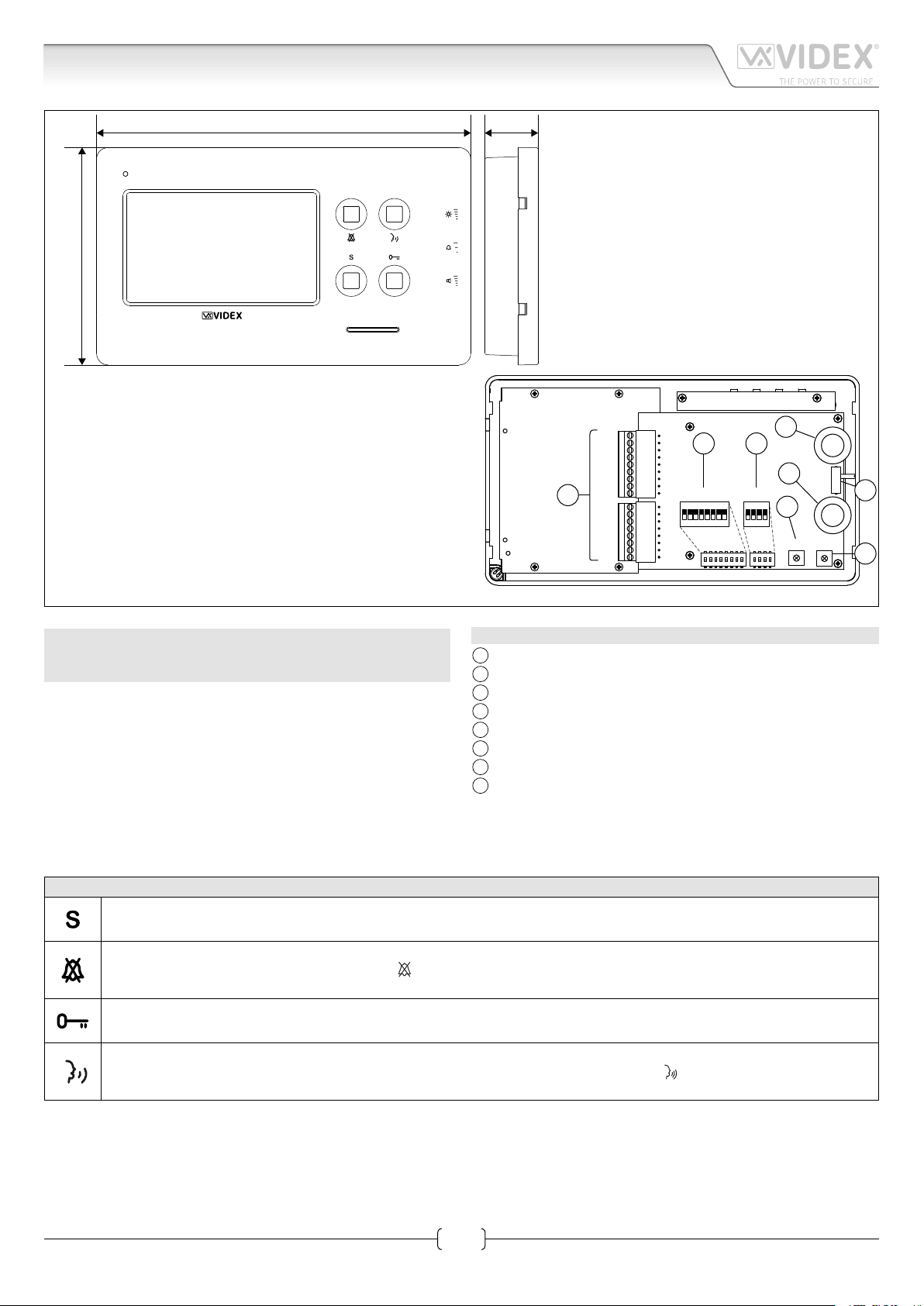
191mm
111 m m
Art.6478 4.3" hands free colour display videophone
27mm
Fig. 1
ART.6478 VX2200 6400 SERIES HANDS FREE VIDEOPHONE
FOR SYSTEMS USING COMPOSITE VIDEO SIGNAL COAX OR
BALANCED TWISTED PAIR
Surface mount hands free intelligent videophone incorporating
a 4.3” Hi-Res full colour active matrix LCD monitor, with “answer/
camera recall”, “door open/concierge call”, “privacy” and one
“service” button plus 2 LED’s one for generic use (door opening
usually) and one to indicate privacy service enabled. Programmable settings: video mode (coax or balanced), privacy duration, melody and number of rings.
Adjustments: call tone volume (3 levels), speech volume, picture hue, contrast and brightness.
VM
–
12Vi
12Vo
SW
SW
EXTC
DOL
AL
A
LB
–
L
GNDV
V/2V
V1
+20
+VD
B C
DSW1
2
4
1
6 7 8
3
5
ON
DSW2
4
3
2
1
LEGEND
A
Connection terminals
B
8 Way dip switch bank to set videophone address
C
4 Way dip switch bank to set video mode
D
Contrast adjustment trimmer
E
Hue adjustment trimmer
F
Speech volume control
G
Brightness control
H
Call tone volume switch
F
VR1
G
SW1
H
E
PT1
ON
PT3PT2
D
PUSH BUTTON OPERATION DURING STANDBY FIG. 1
Service button
When pressed, shorts terminal “SW “ to “SW “ (max 24Vdc 50mA).
Privacy service
Press to enable the privacy service. The LED “ “ turns on. The service is deactivated by pressing again the same button or
when the programmed time expires.
Call the concierge
Press to book a call to the digital concierge if installed on the system.
Camera recall
Press a number of times equal to the ID value of the door panel to switch ON. The LED “ “ turns on.
When the connection is made, press again to end the call.
Art.6478 - Installation instructions
1
66251320-EN - V1.4 - 15/06/16
Page 2
6400 Series
Art.6478 4.3" hands free colour display videophone
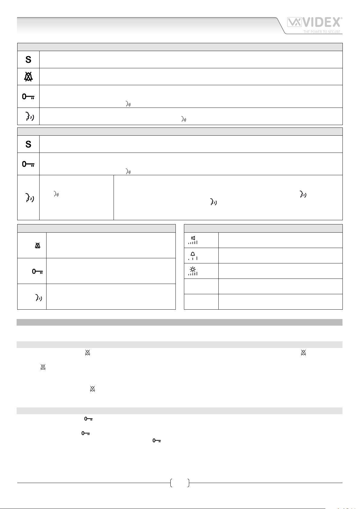
PUSH BUTTON OPERATION DURING A CALL FIG. 1
Service button
When pressed, shorts terminal “SW “ to “SW “ (max 24Vdc 50mA).
Reject the call
During an incoming call, press this button to reject the call. The visitor doesn’t receive any warning of the call rejected.
Open the door
Press to activate the door open relay of the outdoor unit and end the connection.
The unit emits 5 “beeps“ and the“ “ LED will ash, then returns to stand-by mode.
Answer a call
Press to answer the call and start the conversation. The“ “ LED turns on.
PUSH BUTTON OPERATIONS DURING A CONVERSATION FIG. 1
Service button
When pressed, shorts terminal “SW “ to “SW “ (max 24Vdc 50mA).
Open the door
Press to activate the door open relay of the outdoor unit and end the connection after 10 seconds.
The unit emits 5 “beeps“ and the“ “ LED will ash, then returns to stand-by mode.
End conversation
Press to end a call.
The“ “ LED turns o.
Simplex button.
Pressing and holding the button for more than 3 seconds will switch the videomonitor into
SIMPLEX speech mode. Press and hold the button to speak to the caller ( LED will ash
rapidly), release the button to listen (
for 10 seconds the videomonitor will switch o. The videomonitor will revert to duplex
speech when another call is made.
LED will ash slowly). If the button is not pressed
LEDS FIG. 1
Privacy on LED.
LED
LED
LED
PROGRAMMING
All programming options are available only when the system is in stand-by.
PRIVACY SERVICE DURATION
1. Press and keep pressed “
and the unit emits a “beep“;
2. Press “ “ button as many times as required. Each press is equal to 15 minutes: the unit emits a “beep“ every time the button is
pressed. I.E.: press 4 times for 1 hour, 12 for 3 hours. Default: innite. Max value: 20 hours. To program innite privacy time don’t
press any buttons;
3. Wait for some seconds: the “ “ LED turns o and the unit emits a “beep“ that conrms the new setting is properly stored;
4. The unit returns to stand-by mode.
It illuminates when the privacy service is enabled, when
pressing the service button or during programming mode.
Generic use LED.
It is controlled from the terminal “DOL”. Normally
used to signal the door status (open or closed).
ON LED.
It illuminates when the videophone is switched
ON or ashes quickly in “Push To Talk“ mode.
“ button for 10 seconds to enter privacy service duration programming mode: the “ “ LED turns on
CONTROLS FIG. 1
Speech volume control
VR1
(sliding wheel).
Call tone volume switch
SW1
(3 levels).
Brightness control
PT1
(sliding wheel).
PT2
PT3
Hue adjustment trimmer
(rotate left to increase or right to decrease).
Contrast adjustment trimmer
(rotate left to increase or right to decrease).
MELODY TYPE
1. Press and keep pressed “
and then a “beep“;
2. After the “beep” press “ “ buttons to select the next melody: a new melody will play for some seconds then the unit emits a
“beep“. There are 9 melodies available. Note: press “ “ buttons only after the melody is over and the unit emits the “beep“;
3. When desired melody is playing, wait for some seconds: the unit completes the melody and emits a “beep”, then the unit emits a double “beep“ that conrms the new setting is properly stored;
4. The unit returns to stand-by mode.
Note: To set the melody it is required that the videophone is connected in a system where the +20Vdc voltage from Art.893N1 is always enabled.
Art.6478 - Installation instructions
“ button for 10 seconds to enter melody type programming mode: the unit plays the current melody
2
66251320-EN - V1.4 - 15/06/16
Page 3
6400 Series
Art.6478 4.3" hands free colour display videophone
NUMBERS OF RINGS
1. Press and keep pressed “
unit emits a “beep“;
2. Press “ “ button as many rings as required: the unit emits a “beep“ every time the button is pressed. I.E.: press 3 times for 3 rings.
Default value: 6 rings. Max value: 9 rings;
3. Wait for some seconds: the “ “ LED turns o and the unit emits a “beep“ that conrms the new setting is properly stored;
4. The unit returns to stand-by mode.
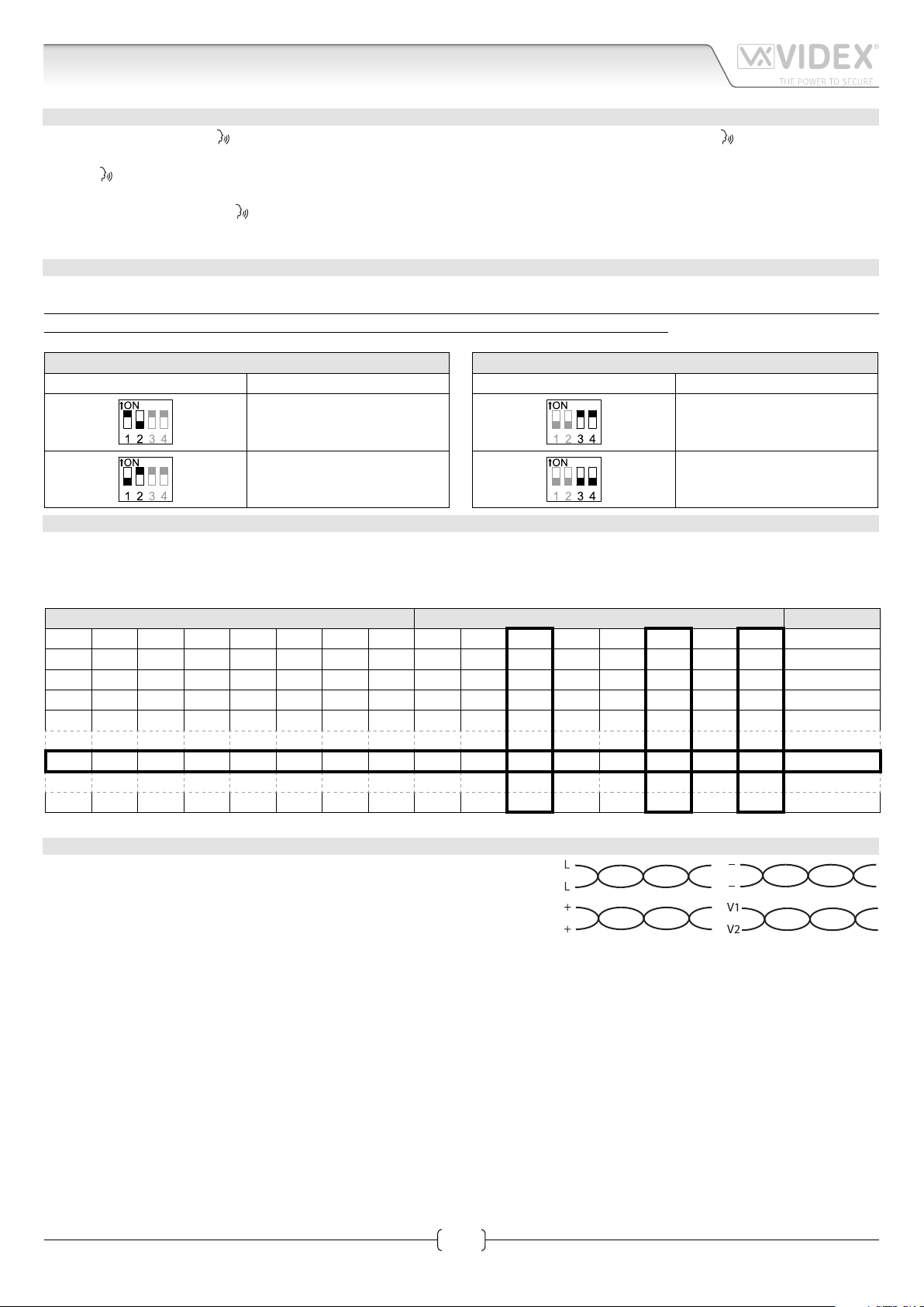
VIDEO MODE SW2
The video mode setup is carried out by the 4 way Dip-Switch accessible from the rear side of the videophone.
Switches 3 and 4 adjust the video signal impedance. When using more than one videomonitor in parallel (without a video
splitter) put both switches in the OFF position on all but the last videomonitor (end of line).
“ button for 10 seconds to enter numbers of rings programming mode: the “ “ LED turns on and the
VIDEO MODE
Switches 1,2 Mode
Coax
Balanced
VIDEOMONITOR/INTERCOM ADDRESS, VIDEO MODE AND TERMINATION SETUP DSW1
Each intercom is addressed in binary (PHONE ID) using the 8 way dipswitches located on the rear of the unit. Each switch corresponds to one bit which can have a value 0 (OFF) or 1 (ON). Each bit corresponds to a decimal weight depending on the position:
Switch 1 = decimal 1, 2=2, 3=4, 4=8, 5=16, 6=32, 7=64, 8=128. I.E. to set the address 37, put switches 1, 3 and 6 on (1+4+32=37).
SWITCHES DECIMAL WEIGHT ADDRESS
8 7 6 5 4 3 2 1 128 64 32 16 8 4 2 1
OFF OFF OFF OFF OFF OFF OFF ON 0 0 0 0 0 0 0 1 1
OFF OFF OFF OFF OFF OFF ON OFF 0 0 0 0 0 0 1 0 2
OFF OFF OFF OFF OFF OFF ON ON 0 0 0 0 0 0 1 1 3
OFF OFF OFF OFF OFF ON OFF OFF 0 0 0 0 0 1 0 0 4
OFF OFF ON OFF OFF ON OFF ON 0 0 1 0 0 1 0 1 37
ON OFF ON ON OFF ON OFF OFF 1 0 1 1 0 1 0 0 180
75 OHM VIDEO TERMINATION
Switches 3,4 Termination
Enabled
Disabled
CABLING 6478 USING CAT.5 CABLE*
Connections:
• One pair must be used to double up the BUS line “L”;
• One pair must be used to double up the power supply ground. The bus ground
must be connected with power supply ground (“GNDV” & “–”);
• One pair must be used to double up the positive power supply +20V;
• One pair must be used for the video signals “V1” and “V/V2”;
• A link is required between “12Vo” & “12Vi”;
• An additional PSU Art.893N1 is required every 50 videomonitors installed in the system.
Max Distance**: 70 metres.
System type: Audio/video door entry systems.
* When this cable is used, in case more videophones are connected in parallel in the same apartment, a local power supply for additional videophones is required.
** By max distance we mean the maximum distance between the door panel and the furthest videophone/intercom
3
Art.6478 - Installation instructions
66251320-EN - V1.4 - 15/06/16
Page 4
6400 Series
Art.6478 4.3" hands free colour display videophone
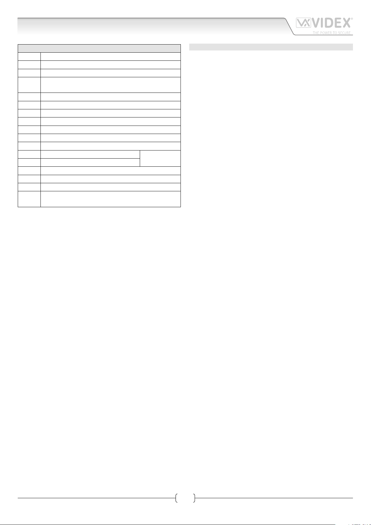
ART.6478 SIGNALS
+VD
V/V2
GNDV Video power supply ground reference
DOL 12Vdc input to supply Aux LED
EXTC Call tone output for extension sounder (Art.512A)
12Vo +12Vdc stabilized output
12Vi Stand-by +12Vdc power supply input
12Vdc output to supply coax video distributor Art.894N
+20 Video power supply 17÷20Vdc
V1 Balanced video signal V1 sync. (balanced video signal mode)
Balanced video signal V2 sync. (balanced video signal mode)
Composite video signal (coax video signal mode)
L BUS line
– BUS line ground reference
LB Local bell input (active low)
AL Alarm input (active low)
SW Service button connection
SW Service button connection
– Power supply ground input / coax video ground
Auxiliary input 200mA 12Vdc for video memory
VM
(Art.6478/MV)
Max 24 Vdc
50mA
TECHNICAL SPECIFICATION
Working Voltage: 17÷20Vdc
Power Consumption: Standby: 10mA
During a conversation: 150mA
Max: 250mA
Working Temperature: -10°C +50°C
Art.6478 - Installation instructions
4
66251320-EN - V1.4 - 15/06/16
Page 5

6400 Series
224kvd119a.dw
g
Art.6478 4.3" colour display videophone
VM
12Vi
12Vo
SW
SW
EXTC
DOL
AL
LB
-
L
GNDV
V/V2
V1
+20
+VD
VM
12Vi
12Vo
SW
SW
EXTC
DOL
AL
LB
-
L
GNDV
V/V2
V1
+20
+VD
Art.6478
Address N.
Art.6478
Address N.
BALANCED
BALANCED
VM
12Vi
12Vo
SW
SW
EXTC
DOL
AL
4
2
LB
-
L
GNDV
V/V2
V1
+20
+VD
VM
12Vi
12Vo
SW
SW
EXTC
DOL
AL
LB
-
L
GNDV
V/V2
V1
+20
+VD
Art.6478
Address N.
Art.6478
Address N.
BALANCED
3
BALANCED
1
Titolo:
13V
ART.521B
115
0
Videx Electronics S.p.A.
Via del Lavoro 1, 63846 Monte Giberto (FM)
Phone: +39 0734 631669 - Fax +39 0734 631669
www.videx.it - info@videx.it
+B
ART.893N1
+
swsw
ON/OFF
Art.4202RV
coax
B.V.
SE
12Vac
_
+12
GND
L
BSSLNCCNO
Notes:
Note:
A
316x
V1
V2 / V
TRD
GNDV
PTE
12T
others
0
Foglio
Data creazione:Title:
07/07/2015
11
Data modifica:
07/07/2015
Autore:
Marco Rongoni
Cod.File:
/
Art.6478 - Installation instructions
5
66251320-EN - V1.4 - 15/06/16
Page 6

6400 Series
www.videx.it - info@videx.it
Title:
Titolo:
224kvd120a.dw
g
Art.6478 4.3" colour display videophone
VM
12Vi
12Vo
SW
SW
EXTC
DOL
AL
LB
-
L
GNDV
V/V2
V1
+20
+VD
VM
12Vi
12Vo
SW
SW
EXTC
DOL
AL
LB
-
L
GNDV
V/V2
V1
+20
+VD
Art.6478
Address N.
Art.6478
Address N.
BALANCED
BALANCED
VM
12Vi
12Vo
SW
SW
EXTC
DOL
AL
4
It is required an additional
power supply for videophones
with memory board. For
Art.6478/MV it is required 1
AMR2-12 each 8 videophones
with memory board
2
LB
-
L
GNDV
V/V2
V1
+20
+VD
VM
12Vi
12Vo
SW
SW
EXTC
DOL
AL
LB
-
L
GNDV
V/V2
V1
+20
+VD
Art.6478
Address N.
Art.6478/MV
Address N.
BALANCED
3
Art.AMR2-12
12Vdc
BALANCED
1
13V
ART.521B
115
0
blu giallo
Art.4845
Videx Electronics S.p.A.
Via del Lavoro 1, 63846 Monte Giberto (FM)
Phone: +39 0734 631669 - Fax +39 0734 631669
+B
ART.893N1
+
swsw
ON/OFF
Unit ID:
1
Art.4283-1
0
Dry Contact Relay
87465321ON109
Relè a contatti puliti
Unit ID:
6
5
4
1C
12Vac
SE
3
Art.4283-1
1
2
1
Notes:
Note:
12Vac
87465321ON109
12Vac
SE
Data creazione:
Foglio
06/07/2015
11
Data modifica:
07/07/2015
Autore:
Marco Rongoni
Cod.File:
/
Art.6478 - Installation instructions
6
66251320-EN - V1.4 - 15/06/16
Page 7

6400 Series
www.videx.it - info@videx.it
228kvd001b.dw
g
Art.6478 4.3" colour display videophone
VM
12Vi
12Vo
SW
SW
EXTC
DOL
AL
LB
-
L
GNDV
V/V2
V1
+20
+VD
VM
12Vi
12Vo
SW
SW
EXTC
DOL
AL
LB
-
L
GNDV
V/V2
V1
+20
+VD
Art.6478
Address N.
Art.6478
Address N.
BALANCED
BALANCED
VM
12Vi
12Vo
SW
SW
EXTC
DOL
AL
4
2
LB
-
L
GNDV
V/V2
V1
+20
+VD
VM
12Vi
12Vo
SW
SW
EXTC
DOL
AL
LB
-
L
GNDV
V/V2
V1
+20
+VD
Art.6478
Address N.
Art.6478
Address N.
BALANCED
3
BALANCED
1
Titolo:
Videx Electronics S.p.A.
Via del Lavoro 1, 63020 Monte Giberto (AP)
Phone: +39 0734 631669 - Fax +39 0734 631669
ART.893N1
0
13V
ART.521B
115
0
Art.8844
h
g
f
e
d
c
b
a
8
7
6
5
4
3
2
1
1
8203-0
BALANCE
Art.8830
87342 5 6
1
ON
NO
C
NC
SL
BS
L
+12
Gnd
Coax
NC
12Vac
SE
+B
+
swsw
2
3
4
Foglio
Data creazione:Title:
07/07/2015
11
Data modifica:
07/07/2015
Notes:
Note:
Autore:
Marco Rongoni
Cod.File:
/
Art.6478 - Installation instructions
7
66251320-EN - V1.4 - 15/06/16
Page 8

6400 Series
228kvd013c.dw
g
Art.6478 4.3" colour display videophone
VM
12Vi
12Vo
SW
SW
EXTC
DOL
AL
LB
-
L
GNDV
V/V2
V1
+20
+VD
VM
12Vi
12Vo
SW
SW
EXTC
DOL
AL
LB
-
L
GNDV
V/V2
V1
+20
+VD
Art.6478
Address N.
Art.6478
Address N.
BALANCED
BALANCED
VM
12Vi
12Vo
SW
SW
EXTC
DOL
AL
4
2
LB
-
L
GNDV
V/V2
V1
+20
+VD
VM
12Vi
12Vo
SW
SW
EXTC
DOL
AL
LB
-
L
GNDV
V/V2
V1
+20
+VD
Art.6478
Address N.
Art.6478
Address N.
BALANCED
3
BALANCED
1
Titolo:
Videx Electronics S.p.A.
Via del Lavoro 1, 63846 Monte Giberto (FM)
Phone: +39 0734 631669 - Fax +39 0734 631669
www.videx.it - info@videx.it
Notes:
Note:
Art.6478 - Installation instructions
Art.8202-8202R
Art.8830
BALANCE
ART.893N1
0
+B
ART.521B
sw
1150 sw +
Coax
NC
SE
12Vac
Foglio
Data creazione:Title:
07/07/2015
11
Data modifica:
07/07/2015
Autore:
Marco Rongoni
Cod.File:
/
8
66251320-EN - V1.4 - 15/06/16
Page 9

6400 Series
6400 Series Wall mounting instructions
1
B
D
A
B
A
Fig. 1
135cm
2
Fig. 2
C
Fig. 3
F
E
F
C
1
2
Fig. 4
1. In order to install the videophone, it is necessary to remove the cover, which contains all the electronics, from the base: press
lightly on the right part of the videophone and simultaneously pulling outwards the left part as shown in Fig. 1.
2. Put the base of the unit on the wall at approx 135cm from the nished oor to match the points for the xing holes “A” (Fig. 2)
remembering that the wires “D” (Fig. 3) must be fed through the large hole “E” (Fig. 3). If you use the ush mounting box 503,
embed it into the wall vertically at approx. 140cm from the nished oor and the base.
3. Following Fig. 3, make the holes “A”, insert the wall plugs “B” and x the base with the screws “C” feeding the wires “D”
through the hole “E”. If you have used the box 503, x the base to the wall through the holes “F” using the screws “C”.
4. As shown in Fig. 4, connect the wires to the removable terminals following the provided installation diagram. Connect the terminal
blocks to the electronics contained in the cover as shown in Fig. 5. Test system before closing.
Contrast and hue trimmers can be adjusted only if the videophone is open. To activate the display and see changes use the
“Camera Recall” function by pressing
Note: while testing the system, it is advisable to hold the cover with your hand.
5. Once testing is complete and all the necessary adjustments are made, close the unit as shown in Fig. 6: rst hook in the right
part and then the left part until you hear a click.
Fig. 5
button.
Fig. 6
Art.6478 - Installation instructions
9
66251320-EN - V1.4 - 15/06/16
Page 10

6400 Series
Note
Art.6478 - Installation instructions
10
66251320-EN - V1.4 - 15/06/16
Page 11

6400 Series
Note
Art.6478 - Installation instructions
11
66251320-EN - V1.4 - 15/06/16
Page 12

MANUFACTURER
The product is CE marked demonstrating its conformity and is for distribution
VIDEX ELECTRONICS S.P.A.
Via del Lavoro, 1 - 63846 Monte Giberto (FM) Italy
Tel (+39) 0734 631669 - Fax (+39) 0734 632475
www.videx.it - info@videx.it
CUSTOMER SUPPORT
All Countries:
VIDEX ELECTRONICS S.P.A.
www.videx.it - technical@videx.it
Tel: +39 0734-631669 - Fax: +39 0734-632475
UK Customers:
VIDEX SECURITY LTD
www.videx-security.com
Tech Line: 0191 224 3174 - Fax: 0191 224 1559
Main UK oce:
VIDEX SECURITY LTD
1 Osprey Trinity Park
Trinity Way
LONDON E4 8TD
Phone: (+44) 0870 300 1240
Fax: (+44) 020 8523 5825
www.videx-security.com
marketing@videx-security.com
Greece oce:
VIDEX HELLAS Electronics
48 Filolaou Str.
11633 ATHENS
Phone: (+30) 210 7521028
(+30) 210 7521998
Fax: (+30) 210 7560712
www.videx.gr
videx@videx.gr
Northern UK oce:
VIDEX SECURITY LTD
Unit 4-7
Chillingham Industrial Estate
Chapman Street
NEWCASTLE UPON TYNE - NE6 2XX
Tech Line: (+44) 0191 224 3174
Phone: (+44) 0870 300 1240
Fax: (+44) 0191 224 1559
Danish oce:
VIDEX DANMARK
Hammershusgade 15
DK-2100 COPENHAGEN
Phone: (+45) 39 29 80 00
Fax: (+45) 39 27 77 75
www.videx.dk
videx@videx.dk
Benelux oce:
VIDEX BENELUX
E3 Iaan, 93
B-9800 DEINZE
Phone: (+32) 9 380 40 20
Fax: (+32) 9 380 40 25
www.videxbenelux.be
info@videxbenelux.be
within all member states of the EU with no restrictions. This product follows
the provisions of the European Directives 2014/30/EU (EMC); 2014/35/EU
(LVD); 2011/65/EU (RoHS): CE marking 93/68/EEC.
 Loading...