

Page 1
5000 Series Eclipse Range
24,50
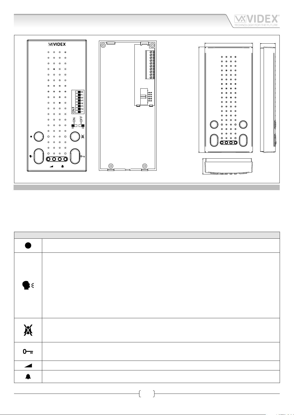
Art.5178N Hands free intercom
74,00
1
2
3
4
5
6
7
8
9
!
10
23,50
164,00
Fig. 1
DESCRIPTION
Voice switched hands free intercom with buttons to control “answer/end conversation/recall/simplex conversation”, “door open”,
“privacy on/o” (programmable duration) and “service” button. In addition there are 4 LED’s* to indicate the status of “answer/
end conversation”, “door open/closed”, “privacy on/ o” and auxiliary “service” status. Call tone and loudspeaker volume controls,
through assigned buttons, are also incorporated on this model. It is possible to program the melody (9 available), the number of
rings (max 9) and the privacy service duration (max 20 hours). Surface wall mount installation.
* The operation of some LED’s and the functions described may require additional cabling
PUSH BUTTONSAND CONTROLS
Service Push Button.
When pressed, shorts internally terminal 1 (“Sb”) and 8 (“Sa”).
Answer / simplex communicaiton / Camera Recall / End Call push button.
• Pressing this button during an incoming call will open the speech in duplex mode allowing free speech with the
caller in both directions (The LED next to this button will illuminate)
• Pressing and holding this button will allow the user to answer a call from a visitor at the door station in SIMPLEX
speech mode (The LED next to the button will ash rapidly): releasing the button will allow the user to listen to
the visitor (The LED next to the button will ash slowly). Press and hold the button when you talk to the visitor and
release the button when you listen to the visitor.
• When the system is in standby, (No calls on the system) operation of this button will open the speech to the door
station. The LED next to the button will illuminate.
• During a conversation, momentary operation of this button will end the call. The LED next to the button will switch
o. The system will automatically switch o when the conversation time expires.
Privacy on/o Push Button.
This button Enables / Disables the privacy function. When privacy is enabled calls will not be received and the LED
next to the button will be illuminated. The duration of the privacy time is set when in the programming mode, privacy can be disabled at any time by operation of this Push Button.
Door Open Push Button.
During a call, operation of this button will release the door from where the call originated. This will be conrmed by
an acoustic tone. If terminal 10 (LD1) is connected, the “door open” LED next to the button will also be illuminated.
Speech line volume control. Adjust during a conversation. Press the right button to increase or the left button to decrease.
Melody volume control. Adjust when the intercom is in standby. Press the right button to increase or the left button
to decrease.
Art.5178N - Installation instructions
1
66250730-EN - V2.0 - 09/10/15
Page 2
5000 Series Eclipse Range
Art.5178N Hands free intercom
PROGRAMMING
MELODIES PROGRAMMING FACTORY PRESET MELODY 1
• Press and hold the two melody buttons
• Press the melody button again (left or right) to listen to the available melodies (maximum 9).
• When the chosen melody has been reached, do not press any buttons wait 3 seconds for the exit beep.
• The new melody is now stored.
NUMBER OF RINGS PROGRAMMING FACTORY PRESET = 6 RINGS
• Press and hold the
• Press the
• Once the number of rings required has been reached, wait 3 seconds for the exit beep.
• The new value is now stored.
PRIVACY DURATION PROGRAMMING FACTORY PRESET = WITHOUT TIME OUT
• Press and hold the
• Press the
minutes (starting from 0 up to a maximum of 20 hours i.e. pressing the button 8 times = 2 hours up to a maximum of 80 presses
for 20 hours). Once the required privacy duration has been reached, wait 3 seconds for the exit beep.To set the privacy with no
time out Press and hold the
3 seconds for the exit beep.
• The new value is now stored.
button as many times as the number of rings required (i.e. 6 presses = 6 rings with a maximum of 9 rings)
button again to set the privacy duration. Each time the button is pressed, it will increase the privacy duration by 15
button (for approx 10 seconds) until the unit emits a beep.
button (for approx 10 seconds) until the unit emits a beep.
button (for approx 10 seconds) until the unit emits a beep do not press any other button wait
(for approx 10 seconds) until the unit plays the current stored melody and emits a beep.
RESTORE TO FACTORY PRESET
• Power on the intercom keeping pressed the
• The intercom will emit a beep to conrm the operation;
• Release the
ENABLE DOOR PANEL AUDIO RECALL FUNCTION FACTORY PRESET = DISABLED
• Remove the intercom cover and disconnect it from the BUS
• Keeping pressed the
• When the privacy LED ashes once to conrm that the function is enabled, release the button.
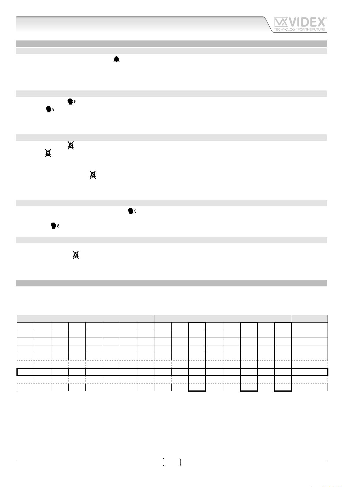
INTERCOM ADDRESS SETUP
Each intercom address is binary (PHONE ID) using the 8 way dipswitches located on the rear of the unit. Each switch correspond to
one bit which can have a value 0 (OFF) or 1 (ON). Each bit corresponds to a decimal weight depending on the position: Switch 1 =
decimal 1, 2=2, 3=4, 4=8, 5=16, 6=32, 7=64, 8=128. I.E. to set the address 37, put switches 1, 3 and 6 on (1+4+32=37).
8 7 6 5 4 3 2 1 128 64 32 16 8 4 2 1
OFF OFF OFF OFF OFF OFF OFF ON 0 0 0 0 0 0 0 1 1
OFF OFF OFF OFF OFF OFF ON OFF 0 0 0 0 0 0 1 0 2
OFF OFF OFF OFF OFF OFF ON ON 0 0 0 0 0 0 1 1 3
OFF OFF OFF OFF OFF ON OFF OFF 0 0 0 0 0 1 0 0 4
button.
button reconnect the intercom to the BUS
SWITCHES DECIMAL WEIGHT ADDRESS
;
OFF OFF ON OFF OFF ON OFF ON 0 0 1 0 0 1 0 1 37
ON OFF ON ON OFF ON OFF OFF 1 0 1 1 0 1 0 0 180
2
Art.5178N - Installation instructions
66250730-EN - V2.0 - 09/10/15
Page 3

5000 Series Eclipse Range
Art.5178N Hands free intercom
INTERCOM CONNECTION BOARD
SIGNALS ON CONNECTION TERMINALS
1
2
3
4
5
6
7
8
9
10
A
B
JP1
Fig. 2
TECHNICAL SPECIFICATION
Housing/Mounting: 5000 Series Intercoms / direct wall mount
Push buttons: Yes, 4
Programming: Yes, carried out by the dip-switches located on the rear of the videophone
Controls: Loudspeaker and call tone volume
Power Supply: Supplied by the BUS line
Power consumption: Stand-by: 7mA
Max: 100mA
Working Temperature: -10 +50 °C
Terminal Signal Description
1 Sb
button terminal 1
2 –LD “Aux” and “Door Open” LEDs ground
3 +12V +12Vdc power supply input
4 GND “Bus” line ground
5 L “Bus” line data
6 LB Local bell input
7 AL Active low alarm input
8 Sa
button terminal 2
9 AUL “Aux” LED power supply input +12Vdc
10 DOL
“Door Open” LED power supply input
+12Vdc
Art.5178N - Installation instructions
3
66250730-EN - V2.0 - 09/10/15
Page 4

5000 Series Eclipse Range
224kau001a.dwg
.
-
Art.5178N Hands free intercom
+12V
L
Address N.
1
2
3
4
5
6
7
8
9
10
Local Bell
12345678
ON
3
Art.5178
1
2
3
4
5
6
7
8
9
10
Address N.
12345678
ON
4
Art.5178
Local Bell
12345678
ON
12345678
ON
1
2
3
4
5
6
7
8
9
10
Local Bell
1
2
3
4
5
6
7
8
9
10
Local Bell
Address N.
230V
Title:
1 Entrance Audio Door Entry System with functional panel
Titolo:
Impianto citofonico ad 1 ingresso con pannello di chiamata tradizionale
1
13V
ART.521B
115
0
Videx Electronics S.p.A.
Via del Lavoro 1, 63020 Monte Giberto (AP)
Phone: +39 0734 631669 - Fax +39 0734 631669
www.videx.it - info@videx.it
ON/OFF
system
Art.5178
+B
swsw
+
+-
12V
Battery
(optional)
Notes:
.
Note:
Art.5178N - Installation instructions
ON
1
4
2
Art.4203-0
4
2
5
3
1
4C
2C
3C
Art.4845
+
-
1
1C
Address N.
SE
12Vac
2
Art.5178
Si raccomanda
di far installare il presente dispositivo
esclusivamente da personale qualificato
We recommend
4C
2C
5C
3C
GND
Art.4845
+
-
1C
2C
3C
Art.4845
+
-
1C
1C
4
2
2C
5C
5
3C4C3
1
4C
5C
1C
4
2
2C
5C
5
3C4C3
1
87
653
A
678
C
B
D
5C
1C
4
2
2C
5C
3C4C3
A
_
+12
SL
G
BSY
NCCNO
L
H
E
F
5
This equipment is installed by a Competent Electrician, Security or Communications Engineer
Data creazione:
27/03/2008
Data modifica:
27/03/2008
Autore:
Marco Rongoni
Cod.File:
Foglio
/ 11
4
66250730-EN - V2.0 - 09/10/15
Page 5

5000 Series Eclipse Range
5000 Series Hands free intercom wall mounting instructions
135cm
A
B
A
B
Fig. 1
Fig. 3
Fig. 5
A
G
E
C
D
H
B
Fig. 2
Fig. 4
Fig. 6
1. As shown in Fig. 1, looking at the rear of the intercom, insert the tip of a at blade screwdriver into one of the two openings
(Fig. 1A) then slightly move the screwdriver in an upward direction to release the front from the back plate and opening the
intercom unit (Fig. 1B). Take care! The back plate of the intercom houses the pcb connection board which is normally connected
to the pcb in the front of the intercom by the ribbon cable, the ribbon cable should not be connected when rst opened.
2. Place the back plate of the intercom against the wall at approximately 135cm (Fig. 2) above nished oor level, then mark the
xing holes taking into account that the cable group A must feed into the opening B (Fig. 3).
3. As shown in Fig. 3, x the back plate of the intercom to the wall feeding the cable group A through opening B.
4. Using a at blade screwdriver connect the wires to the pcb connection board C as shown in Fig. 4, according to the installation
diagram provided.
5. Connect ribbon cable plug D from the front plate into plug E on the pcb connection board as shown in Fig. 5.
6. Close the intercom by hooking the front plate G to the back plate H as described below:
G
• Hook the top of the front plate
to the top of the back plate as shown by pointer A in Fig. 6.
• Move the lower side of the front plate G towards the back plate H and press until the unit locks into the back plate of the intercom.
To open the intercom once installed, rmly grasp the bottom sides of the front plate cover, pull forward in an upward direction to
separate the front cover from the back plate as in Fig. 6.
NB. Please take care when opening to avoid damage, remember that the ribbon cable connects the front plate to the
back plate connector pcb.
5
Art.5178N - Installation instructions
66250730-EN - V2.0 - 09/10/15
Page 6

5000 Series Eclipse Range
Notes
Art.5178N - Installation instructions
6
66250730-EN - V2.0 - 09/10/15
Page 7

5000 Series Eclipse Range
Notes
Art.5178N - Installation instructions
7
66250730-EN - V2.0 - 09/10/15
Page 8

VIDEX ELECTRONICS S.P.A.
Via del Lavoro, 1 - 63846 Monte Giberto (FM) Italy
Tel (+39) 0734 631669 - Fax (+39) 0734 632475
www.videx.it - info@videx.it
Main UK oce:
VIDEX SECURITY LTD
1 Osprey Trinity Park
Trinity Way
LONDON E4 8TD
Phone: (+44) 0870 300 1240
Fax: (+44) 020 8523 5825
www.videx-security.com
marketing@videx-security.com
Greece oce:
VIDEX HELLAS Electronics
48 Filolaou Str.
11633 ATHENS
Phone: (+30) 210 7521028
(+30) 210 7521998
Fax: (+30) 210 7560712
www.videx.gr
videx@videx.gr
Northern UK oce:
VIDEX SECURITY LTD
Unit 4-7
Chillingham Industrial Estate
Chapman Street
NEWCASTLE UPON TYNE - NE6 2XX
Tech Line: (+44) 0191 224 3174
Phone: (+44) 0870 300 1240
Fax: (+44) 0191 224 1559
Danish oce:
VIDEX DANMARK
Hammershusgade 15
DK-2100 COPENHAGEN
Phone: (+45) 39 29 80 00
Fax: (+45) 39 27 77 75
www.videx.dk
videx@videx.dk
Benelux oce:
VIDEX BENELUX
E3 Iaan, 93
B-9800 DEINZE
Phone: (+32) 9 380 40 20
Fax: (+32) 9 380 40 25
www.videxbenelux.be
info@videxbenelux.be
CUSTOMER SUPPORT
All Countries:
VIDEX ELECTRONICS S.P.A.
www.videx.it - technical@videx.it
Tel: +39 0734-631669
Fax: +39 0734-632475
UK Customers:
VIDEX SECURITY LTD
www.videx-security.com
Tech Line: 0191 224 3174
Fax: 0191 224 1559
The product is CE marked demonstrating its conformity and is for distribution within all member states of the EU with no restrictions. This product
follows the provisions of the European Directives 2004/108/ECC (EMC);
2006/95/ECC (LVD) and 93/68/ECC (CE marking).
 Loading...