

Page 1
Audiokit 4KC Series
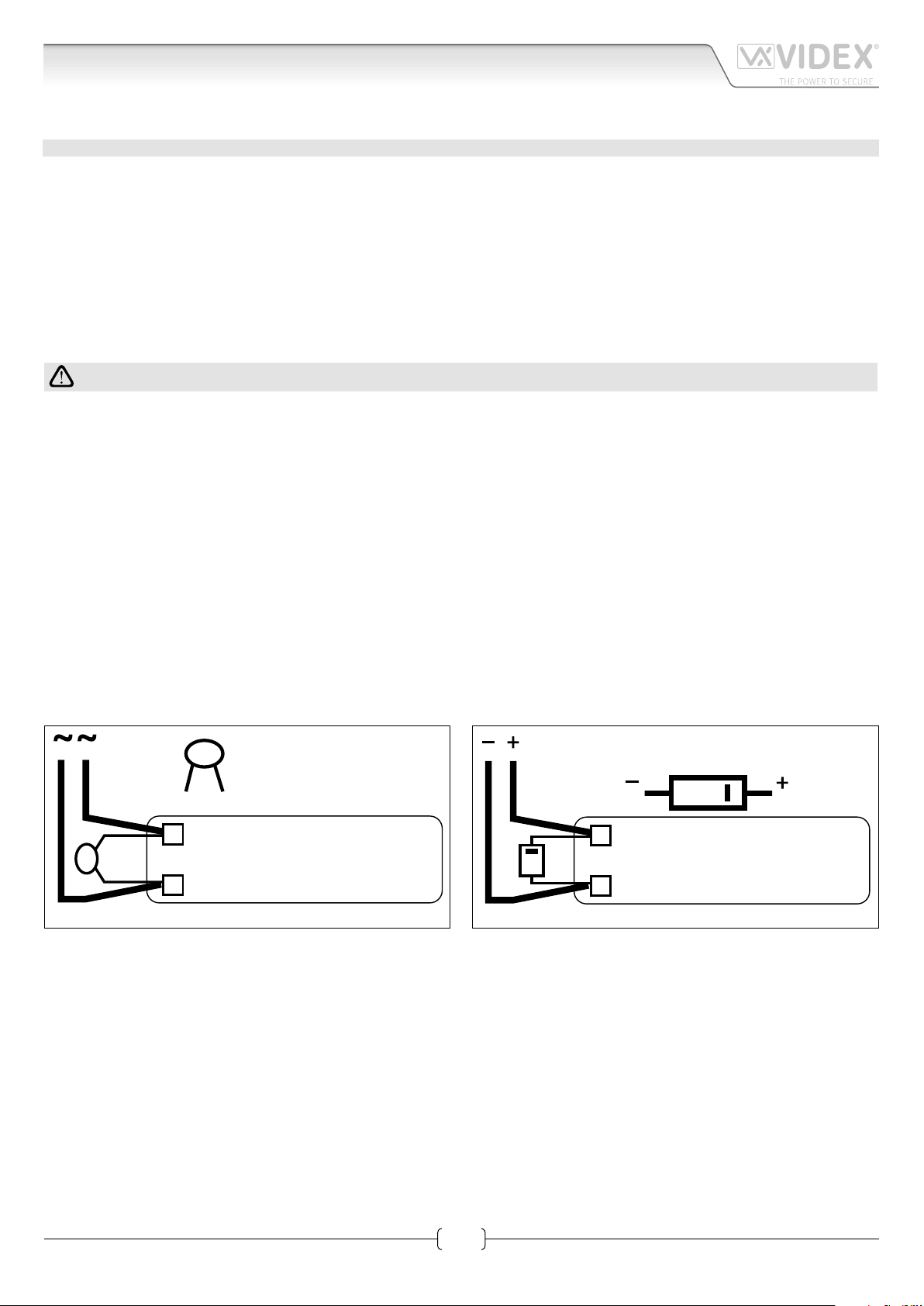
LOCK RELEASE BACK EMF PROTECTION
A varistor must be tted across the terminals on AC lock release
and a diode must be tted across the terminals on a DC
lock release
DIODE
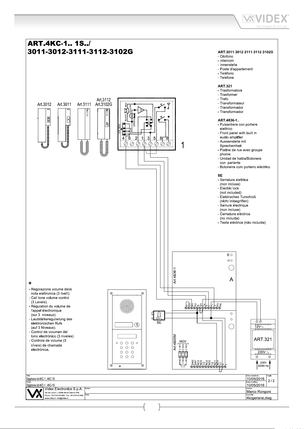
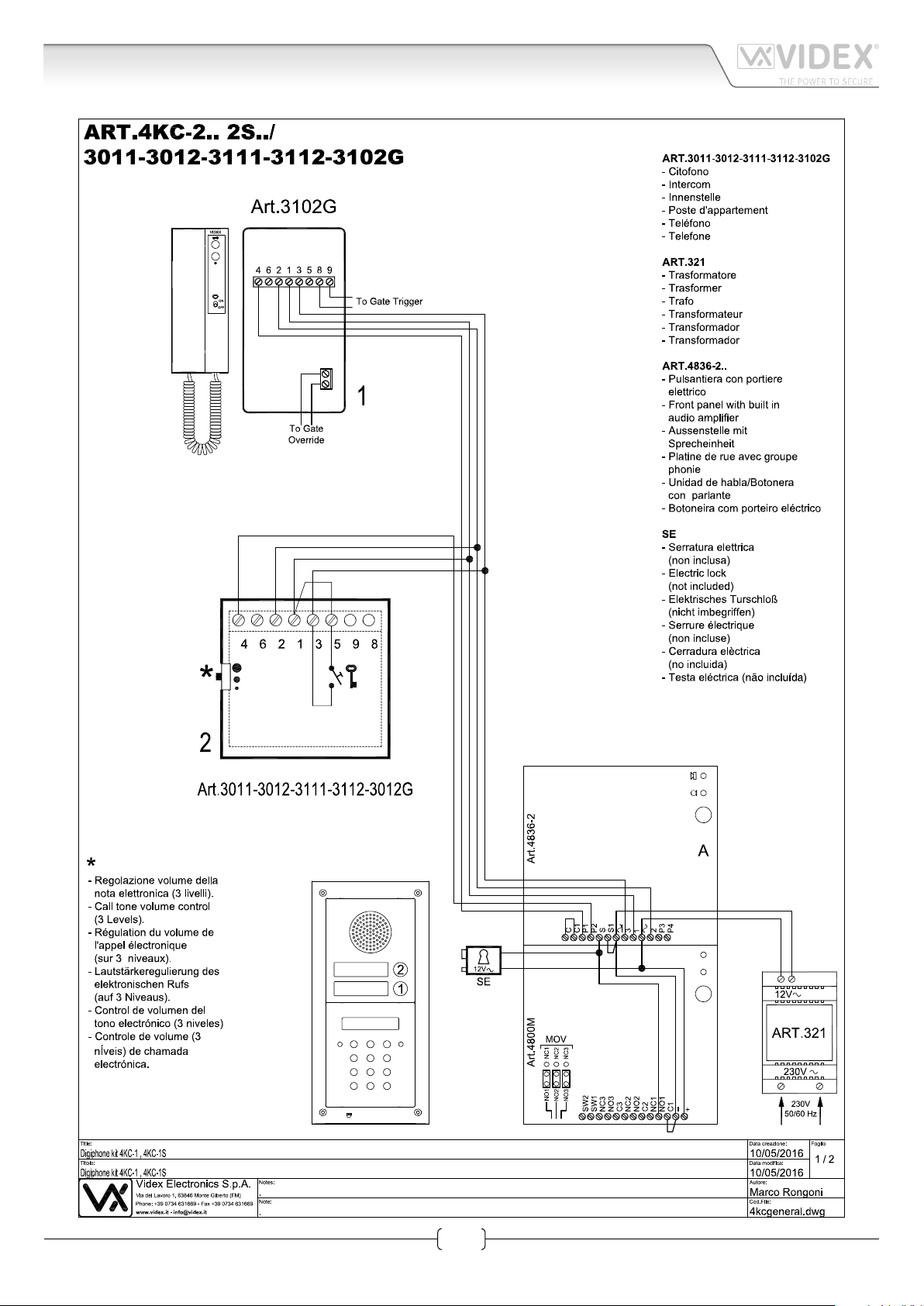
Art.4KC/3011-3012-3111-3112-3102G
Audiokit with digital codelock
GENERAL DIRECTIONS FOR INSTALLATION
In order to achieve the best results from the schematics described it is necessary to install only original VIDEX equipment, strictly
keeping to the items indicated on each schematic and follow these General Directions for Installation:
• The system must be installed according to national rules in force, in any case the running of cables of any intercom unit must be
carried out separately from the mains (see the next paragraph for connection to mains and power supply installation);
• All multipair cables should be compliant to CW1308 specication (0.5mm twisted pair telephone cable);
• Cables for speech line and service should have a max resistance of 10Ω;
• Lock release wires should be doubled up (Lock release wires and power supply wires should have a max resistance of 3Ω);
• The cables sizes above can be used for distances up to 50m. On distances above 50m the cable sizes should be increased to keep
the overall resistance of the cable below the RESISTANCES indicated above;
• Double check the connections before power up; 3 Power up the system then check all functions.
CONNECTION TO MAINS AND POWER SUPPLY MOUNTING INSTRUCTIONS
The system must be installed according to national rules in force, in particular we recommend to:
• Connect the system to the mains through an all-pole circuit breaker which shall have contact separation of at least 3mm in
each pole and shall disconnect all poles simultaneously;
• The all-pole circuit breaker shall be placed for easy access and the switch shall remain readily operable.
POWER SUPPLY INSTALLATION
• Remove the terminal side covers by unscrewing the retaining screws;
• Fix the power supply to a DIN bar or directly to the wall using two expansion type screws;
• Switch o the mains using the circuit breaker mentioned above and then make the connections as shown on the installation
diagrams;
• Check the connections and secure the wires into the terminals;
• Replace the terminal covers and x them using the relevant screws;
• When all connections are made, restore the mains.
(Fig.1B) to suppress back EMF voltages. Connect the components to the lock releases as shown in gures.
VARISTOR (MOV)
12V AC
LOCK RELEASE
Fig.1A
(Fig.1A)
1N4002
12V DC
LOCK RELEASE
Fig.1B
Audiokit 4KC Series - Installation instructions
1
66250360-EN - V3.2 - 15/05/16
Page 2
Audiokit 4KC Series
Art.4KC/3011-3012-3111-3112-3102G
Audiokit with digital codelock
Audiokit 4KC Series - Installation instructions
2
66250360-EN - V3.2 - 15/05/16
Page 3
Audiokit 4KC Series
Art.4KC/3011-3012-3111-3112-3102G
Audiokit with digital codelock
Audiokit 4KC Series - Installation instructions
3
66250360-EN - V3.2 - 15/05/16
Page 4

Audiokit 4KC Series
Wiring Guide Line
All intercoms wiring must run separately from the mains cable.
The cable type should be CW1308 or an equivalent cable. The cable size should comply with the table below.
DISTANCE METERS CABLE SIZE MM2
50 0.35
100 0.5
200 0.75
300 1.0
400 1.5
Max resistance of all lines: 8 Ohm
Before powering the system up, the wiring should be double checked to ensure it complies with the wiring diagram supplied.
TROUBLE SHOOTING GUIDE
In the event of the system not functioning correctly when you power up, the following points can be checked (a multimeter will be
needed).
SYSTEM DEAD
• Check mains input to the transformer.
• Check the 12Vdc (+12 terminal) output from the power supply.
• Check fuses.
• Check for shorts on power supply wires.
SPEECH & LOCK WORKS BUT NO ELECTRONIC CALL TONE
• Check the link between “C” and “C1” terminals of the speaker unit.
• Call wire to terminal “4” of the handset broken on in short circuit; check the walk of the call wire.
NO SPEECH FROM THE DOOR PANEL
• Check and/or adjust the volume operating on trimmers controls on rear of speaker unit.
• Check the wire from terminal “2” of the speaker unit to terminal “2” of the handset.
NO SPEECH FROM THE HANDSET
• Check and/or adjust the volume operating on trimmers controls on rear of speaker unit.
• Check the wire from terminal “1” of the speaker unit to terminal “1” of the handset.
LOCK DOES NOT WORK
• Check on the handset the link between terminals “1” and “5”.
• Check the 13Vac output on the transformer.
• Check the wires of the electric lock.
• Wires section not in conformity with the table above.
FEEDBACK PROBLEM LARSEN EFFECT
• Check that the handset microphone is rmly tted inside its housing.
• Check that the speaker unit microphone is rmly tted inside its housing and nothing is obstructing the microphone hole.
• Adjust the volume operating on trimmer controls on rear of the speaker unit.
HUM ON THE SPEECH LINES
• Check that system cables are not running close to any high voltage or mains cables.
• Check that the system is wired exactly as shown on the wiring diagram.
WE RECOMMEND THIS EQUIPMENT IS INSTALLED BY A COMPETENT ELECTRICIAN, SECURITY OR COMMUNICA
TIONS ENGINEER.
If further assistance is required, call the technical help desk on 0191-2243174 for uk customers or +39 0734631669
for other countries.
4
Audiokit 4KC Series - Installation instructions
66250360-EN - V3.2 - 15/05/16
Page 5

Audiokit 4KC Series
4000 Series Surface and ush mounting door station installation
EXAMPLE: INSTALLING A FOUR MODULE OUTDOOR STATION
B
C
g. 1
Y
H
G
F
G
g. 4 g. 5 g. 6 g. 7
C
A
E
D
g. 2
W
C
H
C
D
C
M
g. 3
L
L
H
M
N
g. 10
g. 14
P
g. 11
M
g. 8
H
Q
H
g. 9
N
g. 12
P O
N
g. 13
g. 15
Audiokit 4KC Series - Installation instructions
g. 16
g. 17
g. 18
5
66250360-EN - V3.2 - 15/05/16
Page 6

Audiokit 4KC Series
4000 Series Surface and ush mounting door station installation
INSTALLING A SURFACE MOUNT DOOR STATION
1. Place the surface box against the wall (165-170cm between the top of the box and the oor level as shown in Fig.1) and mark the
xing holes for the wall plugs and the hole for the cables E (g.2). Observe the orientation of the box with the hinge on the left;
In order to prevent water ingress we highly recommend using a silicon sealant between the wall and the back box C
(Fig.3) and around all holes D (Fig.3);
2. As shown on Fig.2, drill the xing holes A, insert the wall plugs B and feed the cables E through the surface box opening D, x
surface box C to the wall using the screws F;
3. Apply the Y silicon sealant on top of each module as shown in Fig.4;
4. Before installation of the module support frame, hook the modules G to the support frame H as shown in Fig.5 then, as shown
in Fig. 6, t the two anti-tampering locks W for each module (do the same for the second module support frame);
5. When you have more than one support frame, hook the support frame to the surface box starting from the left. For convenience we
will described how to attach the left frame but the same must be carried out for the right frame. As shown in Fig. 7, hook the module
support frame H (complete with modules) to the surface box C moving the frame as suggested from pointers. Ensure that the pivots
L (Fig. 7) go inside the relevant housing M as shown in Fig. 8;
6. As shown on Fig. 9, pull back the module support frame H while moving it slightly to the left as suggested by the pointers;
7. As shown in Fig. 10, open the module support frame H as suggested by the pointer, hook the hinge locks N to the hinges M,
make the required connections using the screwdriver provided P (at blade end) and make the required adjustment by adjusting the settings (through openings O) and adjust trimmers;
8. Repeat the same operations described above for the second module support frame (or for the third if available);
9. When the system has been tested and is working correctly, move back the module support frames carefully, x them to the surface
box using the screwdriver provided P (torx end) and the pin machine torx screws Q (Fig. 11). Note: do not over tighten the screws
more than is necessary.
INSTALLING A FLUSH MOUNTING DOOR STATION
When ush mounting and the number of modules is greater than 3, the required back boxes need to be linked together (before
embedding them in the wall) as shown on Fig. 14, 15 and 16:
• Arrange the back boxes and remove knockouts to allow cables to be fed from one back box to the other;
• Hook the spacers to rst back box then hook the second back box to obtain the result shown on Fig. 16;
1. Protect the module support frame xing holes from dust then embed the back box into the wall (165-170cm between the top
of the box and the oor level as shown on the Fig. 1) feeding the cables E (Fig. 2) through a previously opened hole in the box.
Observe the direction of the box ensuring the hinge is on the left and take care that the box prole is in line with the nished
wall prole;
In order to prevent water ingress we highly recommend using a silicon sealant between the wall and the back box H
(Fig.12);
2. Continue from step 4 of surface mounting instructions , but at step 7 hook the hinge locks N as shown on Fig. 13.
Note: if additional holes are made in the surface box, oxidation problems may appear unless the unprotected metal is
coated with a protective paint.
NOTES
• The screwdriver’s blade has two sides, one at and one torx, to select one of them unplug the blade from the screwdriver body
and plug it into the required side.
• The example shows the use of only one back box bottom hole for wires, this is done to keep le drawings clear. Naturally the
installer can use the left hole or the right or both if required.
HOW TO REMOVE THE CARD NAME HOLDER
• To avoid damage to the module front plate, tape the side that will be in contact with the screwdriver blade;
• lnsert the screwdriver (at side) into the card-holder hole as shown in Fig. 17;
• Move the screwdriver to the left as shown in Fig. 18 to extract the card name holder;
• Edit the card name then replace it inside the holder and ret: insert the holder inside its housing from the left or right side then
push the other side until it clips into place.
Audiokit 4KC Series - Installation instructions
6
66250360-EN - V3.2 - 15/05/16
Page 7

Audiokit 4KC Series
LOCK RELEASE BACK EMF PROTECTION
A varistor must be tted across the terminals on AC lock release
and a diode must be tted across the terminals on a DC
lock release
DIODE
Art.4800 - 4800M Digital codelock module
CODELOCK UNIT MODULES ART.4800 4800M
The module features 12 stainless steel buttons (Keys 0 - 9,
ENTER and CLEAR), 2 LED’s for progress information during
use and programming and a mirror nish stainless steel front
plate (Standard version). With three integral relays each with
common, normally open and normally closed connections and
two inputs to enable the external triggering of relays one and
two (For example, push to exit button). Key presses are signalled
both acoustically and visually while each button press has a tactile feel. Entering the correct code followed by ENTER will activate the relevant relay. Programming is carried out through
the same keypad following a simple programming menu. The
module can be combined with other 4000 Series modules in an
audio or video intercom system.
‘
MAIN FEATURES
• 3 C, NC, NO relay outputs (24Vac/dc – 5A max);
• 3 Programmable secret codes (one for each relay);
• Each relay can be set to be activated for a specic time (01 to 99 seconds) or to work as latch;
• Two active low inputs to command directly the relay 1 and 2;
• Programming menu guarded by a 4-8 digit programmable engineer’s code;
• Visual and Acoustic signal during operating and programming;
• Keypad illumination LEDs;
Fig. 1 - Art.4800 - 4800M
GENERAL DIRECTIONS FOR INSTALLATION
In order to achieve the best results from the schematics described it is necessary to install only original VIDEX equipment, strictly
keeping to the items indicated on each schematic and follow these General Directions for Installation:
• The system must be installed according to national rules in force, in any case the running of cables of any intercom unit must be
carried out separately from the mains;
• All multipair cables should be compliant to CW1308 specication (0.5mm twisted pair telephone cable).
• Cables for speech line and service should have a max resistance of 10 Ohm
• Lock release wires should be doubled up (Lock release wires and power supply wires should have a max resistance of 3 Ohm);
• The cable sizes above can be used for distances up to 50m. On distances above 50m the cable sizes should be increased to keep
the overall resistance of the cable below the RESISTANCES indicated above;
• Double check the connections before power up;
• Power up the system then check all functions.
(Fig.1A)
(Fig.1B) to suppress back EMF voltages. Connect the components to the lock releases as shown in gures.
VARISTOR (MOV)
12V AC
LOCK RELEASE
Fig.1A
Fig.1B
1N4002
12V DC
LOCK RELEASE
Audiokit 4KC Series - Installation instructions
7
66250360-EN - V3.2 - 15/05/16
Page 8

Audiokit 4KC Series
Art.4800 - 4800M Digital codelock module
BUZZER BACK EMF
When using intercoms with buzzer call (Art.924/926, SMART1/2, 3101/2, 3001/2 and 3021/2) add one 0.1uF (100nF) capacitor between terminals 3 and 6 on the telephone.
BUILTIN RELAYS BACK EMF PROTECTION ART.4800M
The Art.4800M includes selectable back EMF protection on the relays. The jumpers marked MOV (One jumper for each relay) are
used to select the protection type. When using a fail secure lock with connections C & NO the jumper should be in the NO position.
When using a fail open lock with connections C & NC the jumper should be in the NC position and when using the codelock to
trigger a gate controller or another third party controller the jumper should be removed completely (This disables the protection
on the relay).
PROGRAMMING SEE ALSO THE RELEVANT FLOW CHART
• Enter the “ENGINEER’S CODE”: rst time type six times “1” (111111 factory preset) and press “ENTER” (The red LED will illuminate);
• Conrm “ENGINEER’S CODE” (typing again the same) or type the new code (4 to 8 digits) then press “ENTER” (Melody). Pressing
twice the “ENTER” button without changing the “ENGINEER’S CODE”, will exit from the programming;
• Enter the code (4 to 8 digits) to enable “RELAY 1” or re-enter the existing code then press “ENTER” (Melody);
• Enter the “RELAY 1” operation time (2 digits 01 to 99 I.E. 05=5 seconds, 00= remain open time) or re-enter the existing time then
press “ENTER” (Melody);
• Enter the code (4 to 8 digits) to enable “RELAY 2” or re-enter the existing code then press “ENTER” (Melody);
• Enter the “RELAY 2” operation time (2 digits 01 to 99 I.E. 05=5 seconds, 00= remain open time) or re-enter the existing time then
press “ENTER” (Melody);
• Enter the code (4 to 8 digits) to enable “RELAY 3” or re-enter the existing code then press “ENTER” (Melody);
• Enter the “RELAY 3” operation time (2 digits 01 to 99 I.E. 05=5 seconds, 00= remain open time) or re-enter the existing time then
press “ENTER” (Melody);
• The system is ready to use (the red LED will be o).
PROGRAMMING NOTES
• After pressing enter following a command, press “ENTER” a further twice to exit the programming menu.
RETURN SYSTEM TO PRESET ENGINEER’S FACTORY CODE
• Turn o power to code lock;
• Keep “ENTER” button pressed while turning the power back on;
• Release “ENTER” button;
• The engineer’s code is now set to “111111” (six times one).
OPERATION
• Type in the programmed code and press “ENTER”;
• If the code is correct, the green LED will illuminate for approx. 2 seconds and the relay relevant to the code will operate for the programmed time;
• If a wrong code is entered, a continuous melody will sound
for 4 or more seconds, according to the number of mistakes;
• To switch o any relay while operating, type in the relevant
code then press the “CLEAR” button;
OPERATION NOTES
• To operate relays together, set the same code for each relay;
• If a wrong code is entered, the system will lock out for 5 seconds which will increase each time a wrong code is entered.
The system will operate only when the correct code is entered.
TERMINALS:
SW2 Relay 2 command signal (active low)
SW1 Relay 1 command signal (active low)
NC3 Relay 3 normally closed contact
NO3 Relay 3 normally open contact
C3 Relay 3 common contact
NC2 Relay 2 normally closed contact
NO2 Relay 2 normally open contact
C2 Relay 2 common contact
NC1 Relay 1 normally closed contact
NO1 Relay 1 normally open contact
C1 Relay 1 common contact
+
12/24Vac/dc power input
Max
24Vac/dc
3A
Audiokit 4KC Series - Installation instructions
8
66250360-EN - V3.2 - 15/05/16
Page 9

Audiokit 4KC Series
Main UK office:
VIDEX SECURITY LTD
1 Osprey Trinity Park
Trinity Way
LONDON E4 8TD
Phone: (+44) 0870 300 1240
Fax: (+44) 020 8523 5825
www.videx-security.com
marketing@videx-security.com
Northern UK office:
VIDEX SECURITY LTD
Unit 4-7
Chillingham Industrial Estate
Chapman Street
NEWCASTLE UPON TYNE - NE6 2XX
Tech Line: (+44) 0191 224 3174
Phone: (+44) 0870 300 1240
Fax: (+44) 0191 224 1559
Greece offi ce:
VIDEX HELLAS Electronics
48 Filolaou Str.
11633 ATHENS
Phone: (+30) 210 7521028
(+30) 210 7521998
Fax: (+30) 210 7560712
www.videx.gr
videx@videx.gr
Danish offi ce:
VIDEX DANMARK
Hammershusgade 15
DK-2100 COPENHAGEN
Phone: (+45) 39 29 80 00
Fax: (+45) 39 27 77 75
www.videx.dk
videx@videx.dk
Benelux offi ce:
VIDEX BENELUX
E3 Iaan, 93
B-9800 DEINZE
Phone: (+32) 9 380 40 20
Fax: (+32) 9 380 40 25
www.videxbenelux.be
info@videxbenelux.be
VIDEX ELECTRONICS S.P.A.
Via del Lavoro, 1 - 63846 Monte Giberto (FM) Italy
Tel (+39) 0734 631669 - Fax (+39) 0734 632475
www.videx.it - info@videx.it
Art.4800 - 4800M Digital codelock module
TECHNICAL SPECIFICATION
Power Supply: 12/24 Vac/dc – 2VA
Power Consumption: Stand-by: 20mA
Operating: 70mA
Working Temperature: -10 +50° C
PROGRAMMING FLOWCHART
ENTER “ENGINEER’S CODE“
Red LED will be ON
AND PRESS “ENTER“
First time 6 times 1 "111111"
factory preset
Melody
Melody
Melody
Melody
Melody
Melody
Melody
CONFIRM OR CHANGE “ENGINEER’S CODE“
AND PRESS “ENTER“
ENTER “ACCESS 1 CODE“
AND PRESS “ENTER“
ENTER “ACCESS 1 TIME“
AND PRESS “ENTER“
ENTER “ACCESS 2 CODE“
AND PRESS “ENTER“
ENTER “ACCESS 2 TIME“
AND PRESS “ENTER“
ENTER “ACCESS 3 CODE“
AND PRESS “ENTER“
ENTER “ACCESS 3 TIME“
AND PRESS “ENTER“
Type again six times “1”
or the new enginner’s code 4 to 8 digits
Code to enable
relay 1
4 to 8 digits
2 digits (01 to 99)
I.E. 05 = 5 seconds
00 = remain open time
Code to enable
relay 2
4 to 8 digits
2 digits (01 to 99)
I.E. 05 = 5 seconds
00 = remain open time
Code to enable
relay 3
4 to 8 digits
2 digits (01 to 99)
I.E. 05 = 5 seconds
00 = remain open time
Red LED will be OFF
Audiokit 4KC Series - Installation instructions
SYSTEM READY TO USE
9
66250360-EN - V3.2 - 15/05/16
Page 10

Audiokit 4KC Series
Notes
Audiokit 4KC Series - Installation instructions
10
66250360-EN - V3.2 - 15/05/16
Page 11

Audiokit 4KC Series
Notes
Audiokit 4KC Series - Installation instructions
11
66250360-EN - V3.2 - 15/05/16
Page 12

VIDEX ELECTRONICS S.P.A.
Via del Lavoro, 1 - 63846 Monte Giberto (FM) Italy
Tel (+39) 0734 631669 - Fax (+39) 0734 632475
www.videx.it - info@videx.it
Main UK offi ce:
VIDEX SECURITY LTD
1 Osprey Trinity Park
Trinity Way
LONDON E4 8TD
Phone: (+44) 0870 300 1240
Fax: (+44) 020 8523 5825
www.videx-security.com
marketing@videx-security.com
Greece offi ce:
VIDEX HELLAS Electronics
48 Filolaou Str.
11633 ATHENS
Phone: (+30) 210 7521028
(+30) 210 7521998
Fax: (+30) 210 7560712
www.videx.gr
videx@videx.gr
Northern UK offi ce:
VIDEX SECURITY LTD
Unit 4-7
Chillingham Industrial Estate
Chapman Street
NEWCASTLE UPON TYNE - NE6 2XX
Tech Line: (+44) 0191 224 3174
Phone: (+44) 0870 300 1240
Fax: (+44) 0191 224 1559
Danish offi ce:
VIDEX DANMARK
Hammershusgade 15
DK-2100 COPENHAGEN
Phone: (+45) 39 29 80 00
Fax: (+45) 39 27 77 75
www.videx.dk
videx@videx.dk
Benelux offi ce:
VIDEX BENELUX
E3 Iaan, 93
B-9800 DEINZE
Phone: (+32) 9 380 40 20
Fax: (+32) 9 380 40 25
www.videxbenelux.be
info@videxbenelux.be
CUSTOMER SUPPORT
All Countries:
VIDEX ELECTRONICS S.P.A.
www.videx.it - technical@videx.it
Tel: +39 0734-631669
Fax: +39 0734-632475
UK Customers:
VIDEX SECURITY LTD
www.videx-security.com
Tech Line: 0191 224 3174
Fax: 0191 224 1559
The product is CE marked demonstrating its conformity and is for distribution within all member states of the EU with no restrictions. This product follows the provisions of the European Directives 2014/30/UE (EMC);
2014/35/UE (LVD) and 93/68/ECC (CE marking).
 Loading...