

Page 1
Art.4800
Questo modulo presenta nella parte f rontale una tasti era a
12 pulsanti (tasti da “0” a “9” più i tasti “ENTER” e
“CLEAR”) in acciaio inossidabile, 2 LED per le indicazioni
di funzionamento ed i LED d’illuminazione tastiera; il tutto
è protetto da una placca frontal e in acciaio inossidabile
lucidato a specchio (versione standard). L’unità è
equipaggiata con 3 relé attraverso i quali è possibile
abilitare altrettanti servizi (apertura porta, apertura
cancello ecc.) digitando il relativo codice segreto. Segnali
acustici e visivi (LED frontali rosso e verde) facilitano l e
operazioni di utilizzo e programmazione. Il modulo può
essere impiegato singolarmente o in abbinamento ad alt ri
moduli in sistemi citofonici/videocitofonici
e di comando;
MODULI TASTIERA DIGITALE
Digital Codelock Unit Module
Modulo Tastiera digitale
Art.4800
(01..99 secondi) o per il funzionamento a commutazione;
CARATTERISTICHE PRINCIPALI
- 3 relé con contatti C, NC, NO (24Vac/dc – 5A max);
- 3 Codici programmabili (uno per ogni relé);
- Ciascun relé può essere programmato per l’attivazione temporanea
- 2 Ingressi (attivo basso) per comandare direttamente i relé 1 e 2;
- Menù di programmazione protetto da un codice segreto programmabile;
- Segnali acustici e visivi durante il funzionamento;
- LED di illuminazione tastiera
NORME GENERALI D’INSTALLAZIONE
Per eseguire una corretta installazione è necessario impiegare
caso si consiglia di prevedere, per i conduttori dell’impianto, una
canalizzazione distinta da quella della linea elettrica (vedi paragrafo
seguente per il collegamento alla linea elettrica e l’installazione
esclusivamente parti VIDEX, seguire co n scrupolo quanto indicato negli
schemi di collegamento e tenere presenti le norme generali
d’installazione:
dell’alimentatore);
- Realizzare gli impianti secondo le vigenti normative nazionali ed in ogni
di alimentazione;
• resistenza complessiv a i nferiore a 10 Ohm per quell i della linea f onica
• resistenza complessiva inferiore a 3 Ohm per quelli della serratura e
- Impiegare conduttori con sezioni tali da avere:
- Verificare le connessioni prima di dare alimentazione all'impianto;
- Alimentare l’impianto ed eseguire il collaudo verificandone tutte le
funzioni
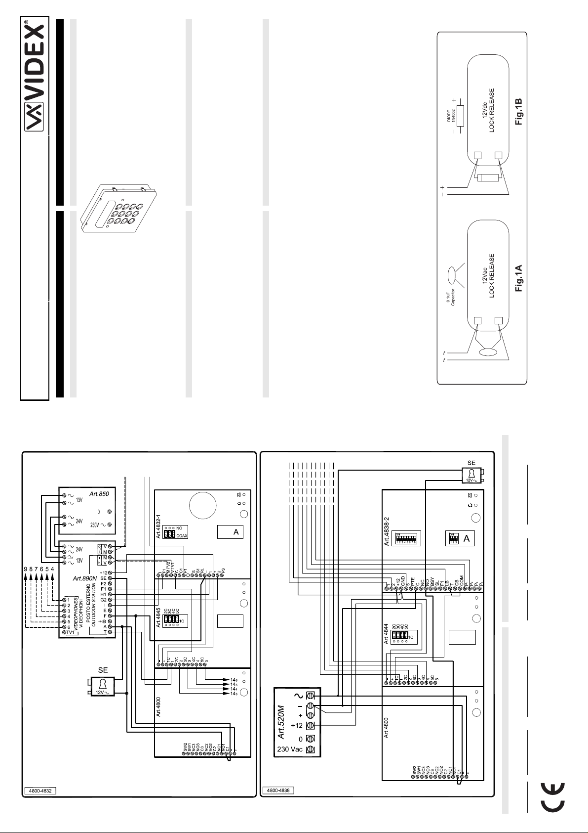
Azionamento Serratura – Protezione dai Disturbi
L’azionamento della serratura elettrica può provocare degli spike, per
evitare tale inconveniente si consiglia di collegare tra i terminali della
serratura un condensatore (Fig.1A) o un diodo (Fig.1B) a seconda c he la
serratura sia in alternata o in continua.
Buzzer Protezione dai Disturbi
Utilizzando citofoni con chiamata su buzzer (Art.924/926, SMART1/2,
3101/2, 3001/2 e 3021/2) inserire un condensat ore da 0,1 uF tra i morsetti
6 e 3.
INSTALLATION INSTRUCTION ISTRUZIONI D’INSTALLAZIONE
Art.4800
This module has on the front a 12 stai nless steel button
keypad (keys from “0” to “9” p lu s “ENTER” and “CLEAR”
keys), 2 LEDS for operation signalling, the keypad
illumination LEDs and a mirror stainless steel f ront plate
(standard version). Codelock unit module has 3 built-in
Art.4800
CODELOCK UNIT MODULES
relays that allow to enable up to 3 servi ces (door-open,
seconds) or to work as latch;
- 3 C, NC, NO relay outputs (24Vac/dc – 5A max);
- 3 Programmable secret codes (one for each relay);
- Each relay can be set to be activated for a spec ific time (01 to 99
- Two active low inputs to command directly the relay 1 and 2;
- Programming menu guarded by a 4-8 digit programmable secret code;
- Visual and Acoustic signal during operating and programming;
- Keypad illumination LEDs;
gate-open etc.) by typing the program med secret codes.
Acoustic and visual (green and red front LEDs) signals
facilitate the use and the programming operations. This
module can be used individually or combined with other
modules on an audio or video door entry systems.
MAIN FEATURES
In order to achieve the best results from the schematics described it is
GENERAL DIRECTIONS FOR INSTALLATION
case the running of cables of any interco m unit must be carried out
separately from the mains;
(0.5mm twisted pair telephone cable).
Ohm
power supply wires should have a max resistance of 3 Ohm);
distances above 50m the cable sizes should be increas ed to keep the
overall resistance of the cable below the RESISTANCES indicated
necessary to install only original VIDEX equipment, strictly keeping to the
items indicated on each schematic and follow these General Dire ctions for
Installation:
- The system must be installed according to nationa l rule s in force, in any
- All multipair cables should be compliant to CW1308 specification
- Cables for speech line and service should have a max resistance of 10
- Lock release wires should be doubled up (Lock release wires and
above;
- The cable sizes above can be used for distances up to 50m. On
- Double check the connections before power up;
- Power up the system then check all functions.
Lock Release Back EMF Protection
A capacitor must be fitted across the terminals on AC lock release
(Fig.1A) and a diode must be fitted across the terminals on a DC lock
release (Fig.1B) to suppress back EMF voltages.
Connect the components to the lock releases as shown in figures.
Clienti di tutti i Paesi Clienti UK
INFORMAZIONI ASSISTENZA CLIENTI
Buzzer Back EMF
Tech Line 0191 224 3174
Fax 0191 224 1559
VIDEX Security LTD
www.videx-security.com
Tel.+39 0734 631669
Fax +39 0734 632475
VIDEX Electronics S.p.A.
www.videx.it – technical@videx.it
PrtCode:66250070.doc 21/10/2005 Rev.1.1
When using intercoms with buzzer call (Art.9 24/926, SMART1/2, 3101/2,
3001/2 and 3021/2) add one 0,1uF capacitor between terminals 6 and 3.
Il prodotto è marchiato CE a dimostrazione del la sua conformità e pu ò essere distribui to
liberamente all’interno dei paesi membri dell’unione europea EU.
Questo prodotto è conforme alle direttive Europee
89/336/EEC & 92/31/EEC (EMC),
73/23/EEC (LVD) e 93/68/EEC (Marcatura CE).
All Countries Customers UK Customers
CUSTOMER SUPPORT INFORMATION
Tech Line 0191 224 3174
Fax 0191 224 1559
VIDEX Security LTD
www.videx-security.com
The product is CE marked demonstrating it s conformity and is for distribution within all
member states of the EU with no restrictions.
This product follows the provisions of the European Dir ectives
89/336/EEC & 92/31/EEC (EMC),
– technical@videx.it
VIDEX Electronics S.p.A.
www.videx.it
Tel.+39 0734 631669
73/23/EEC (LVD) and 93/68/EEC (CE marking).
Fax +39 0734 632475
PrtCode:66250070.doc 21/10/2005 Rev.1.1
Page 2
PrtCode:66250070.doc 21/10/2005 Rev.1.1
- If a wrong code is entered, the s ystem will l ock o ut for 5 seco nds which
will increase each time a wrong code is entered. The system will
operate only when the correct code is entered.
press the “CLEAR” button;
operate for the programmed time;
more seconds, according to the number of mistakes;
OPERATION
- Type in the programmed code and press “ENTER”;
- If the code is right, the green LED will illuminate and the relay will
- If a wrong code is “ENTER”ed, a continuous melody will sound for 4 or
- To switch off any relay while operating, type in the relevant code then
Operation Notes
- To operate relays together, set the same code for each relay;
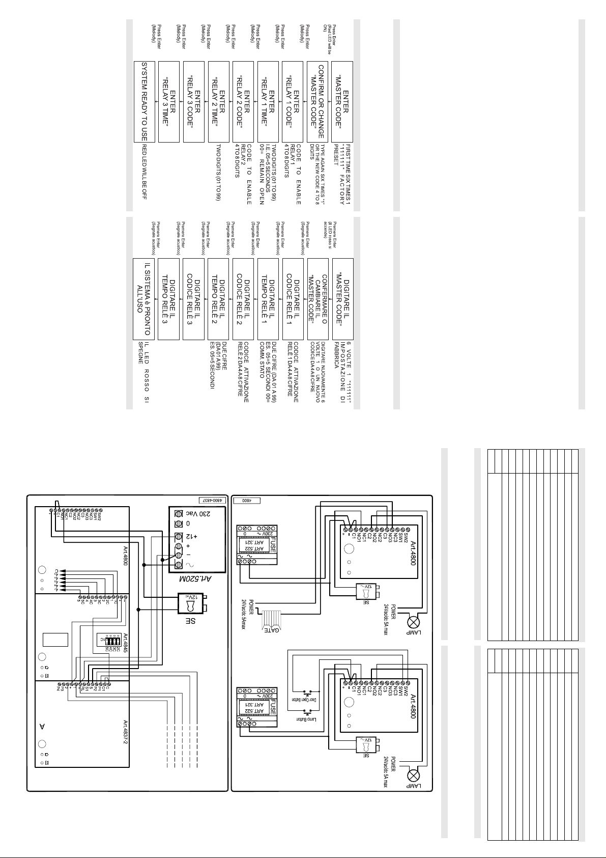
CODELOCK UNIT PROGRAMMING FLOW-CHART
- Release “ENTER” button;
- The master code is now set at “111111” (six times one).
programming.
- The system is ready to use (the red LED will be off). Programming Notes
- After the confirmation of an entered data by pressi ng the “ENTER”
button, by pressing twice the same button you can exit from the
- Enter the code (4 to 8 digits) to enable “RELAY 3” or leave the existing
- Enter the “RELAY 3” operation time (2 digits 01 to 99 I.E. 05=5
code then press “ENTER” (Melody);
seconds, 00= remain open time) or leave the existing time then press
“ENTER” (Melody);
- Enter the code (4 to 8 digits) to enable “RELAY 2” or leave the existing
- Enter the “RELAY 2” operation time (2 digits 01 to 99 I.E. 05=5
code then press “ENTER” (Melody);
seconds, 00= remain open time) or leave the existing time then press
“ENTER” (Melody);
- Enter the code (4 to 8 digits) to enable “RELAY 1” or leave the existing
- Enter the “RELAY 1” operation time (2 digits 01 to 99 I.E. 05=5
“ENTER” button without changing the “MASTER CODE”, will exit from
the programming;
code then press “ENTER” (Melody);
seconds, 00= remain open time) or leave the existing time then press
“ENTER” (Melody);
RETURN SYSTEM TO PRESET MASTER FACTORY CODE
- Turn off power to code lock;
- Keep “ENTER” button pressed while turning back on the power;
(4 to 8 digits) then press “ENTER” (Melody). Pressing twice the
- Confirm “MASTER CODE” (typing again the sa me) or type t he new one
PROGRAMMING (SEE ALSO THE RELEVANT FLOW CHART)
- Enter the “MASTER CODE”: first time type six times “1” (111111 fac tory
preset) and press “ENTER” (The red LED will illuminate);
- Il sistema è pronto all’uso (il LED rosso si spegne).
Note di Programmazione
funzionerà solo digitando un codice corretto.
- Se viene digitato un codice errato, l’unità si blocca per 5 secondi: il
codice d’attivazione per ciascun relé.
tempo di blocco aumenta in base al numero di errati ins erimenti. L’un ità
tempo programmato;
al numero di digitazioni errate;
codice quindi premere il tasto “CLEAR”.
FUNZIONAMENTO
- Digitare il codice segreto e premere “ENTER”;
- Se il codice è corretto, il LED ver de si accende ed il relé si attiva per il
- Se il codice è errato, una melodia lo segnala per 4 secondi o più in base
- Per disattivare uno dei relé mentre è in funzione, digitare il relativo
Note di Funzionamento
- Per far funzionare i relé contemporaneamente, impostare lo stesso
FLOW-CHART DI PROGRAMMAZIONE TASTIERA DIGITALE
“ENTER”, premendolo nuovamente per due volte consecutive, si esce
dalla programmazione.
- Dopo aver confermato l’inserimento di un dato premendo il tasto
RIPORTARE L’UNITÀ ALLE IMPOSTAZIONI DI FABBRICA
- Togliere l’alimentazione alla tastiera;
- Tenendo premuto il tasto “ENTER”, dare nuovamente alime ntazion e;
- Rilasciare il tasto “ENTER”;
- Il codice master è nuovamente impostato a “111111” (sei volte uno).
- Digitare il tempo di funzionamento del “RELÈ 3” quindi premere
- Digitare il codice di attivazione ( da 4 ad 8 cifre) del “RELÈ 3” quindi
“ENTER” (segnale acustico);
- Digitare il tempo di funzionamento del “RELÈ 2” quindi premere
premere “ENTER” (segnale acustico);
“ENTER” (segnale acustico);
- Digitare il tem po di funzionamento del “RELÈ 1” (2 cifre da 01 a 99
- Digi tare il codice di attivazione (da 4 ad 8 cifre) del “RELÈ 2” quindi
premere “ENTER” (segnale acustico);
(segnale acustico);
- Digi tare il codice di attivazione (da 4 ad 8 cifre) del “RELÈ 1” quindi
Es.05=5 secondi 00=Commutazione di stato) q uindi premere “ENTER”
acustico). Premendo due volte “ENTER” senza modificare il “MASTER
CODE” si esce dalla programmazione;
premere “ENTER” (segnale acustico);
uno nuovo (da 4 ad 8 cifre) quindi premere “ENTER” (segnale
- Confermare il “MASTER CODE” (digitandolo nuovamente) o digita rne
fabbrica) e premere “ENTER” (il LED rosso si accende);
PROGRAMMAZIONE (VEDI RELATIVO DIAGRAMMA DI FLUSSO)
- Digitare il “MASTER CODE”: 6 volte “1” (111111 impostazione di
PrtCode:66250070.doc 21/10/2005 Rev.1.1
NO3
Relay 3 normally open contact
NO3
Relé 3 contatto normalmente aperto
NC3
Relay 3 normally closed contact
NC3
Relé 3 contatto normalmente chiuso
TERMINALS:
SW1
SW2 Relay 2 command signal (active low)
Relay 1 command signal (active low)
MORSETTIERA:
SW2
SW1
Comando d’abilitazione del relé 2 (ingresso attivo basso)
Comando d’abilitazione del relé 1 (ingresso attivo basso)
INSTALLATION DIAGRAMS SCHEMI DI INSTALLAZIONE
Working Temperature: -10 +50 C
Temperatura di lavoro: -10 +50 C
Power Supply: 12/24 Vac/dc – 2A
Power Consumption: 30mA max
Tensione d’alimentazione: 12/24 Vac/dc
Assorbimento: 30mA max
TECHNICAL SPECIFICATION
SPECIFICHE TECNICHE
NO1
C1 Relay 1 common contact - +
Relay 1 normally open contact
12/24Vac/dc power input
NO1
C1
-
+
Relé 1 contatto normalmente aperto
Relé 1 contatto comune
Ingresso d’alimentazione 12/24Vac/dc
NC1
Relay 1 normally closed contact
NC1
Relé 1 contatto normalmente chiuso
C2
Relay 2 common contact
C2
Relé 2 contatto comune
NO2
Relay 2 normally open contact
NO2
Relé 2 contatto normalmente aperto
NC2 Relay 2 normally closed contact
NC2
Relé 2 contatto normalmente chiuso
C3
Relay 3 common contact
C3
Relé 3 contatto comune
 Loading...