

Page 1
3600 Series
218
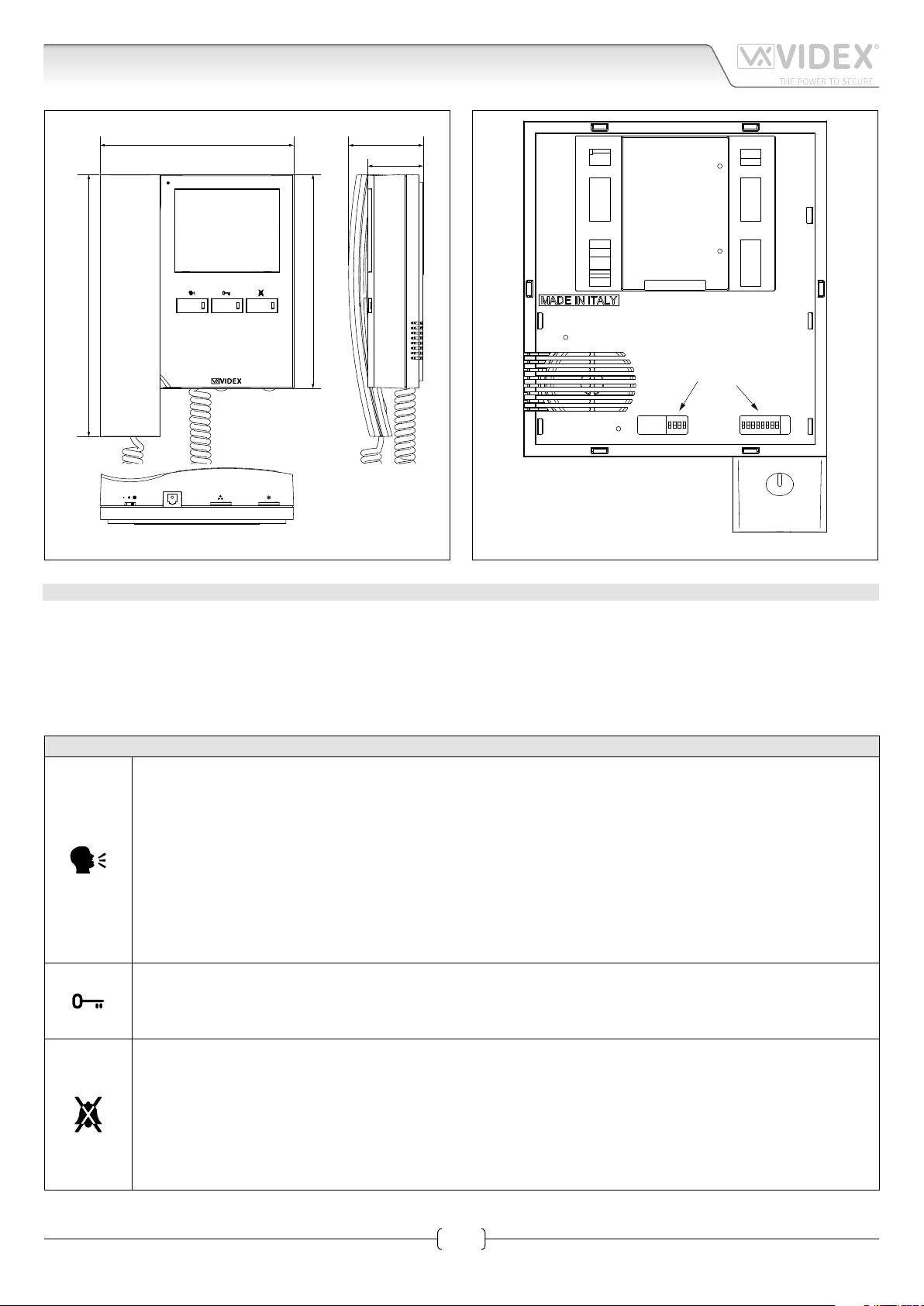
Art.3678 Videophone with hands free facility
Fig. 1
161
178
62
46
Fig. 2
DESCRIPTION
Intelligent videophone for the VX2200 digital system incorporating a 3,5” full colour active matrix LCD monitor, with “door open”,
“answer/camera recall”, “privacy/service” buttons plus 3 LEDs related to the operation of the buttons. The videophone can work as
hands free unit or as standard videophone using the handset.
Programmable settings: video mode (coax or balanced), melody, number of rings and privacy duration.
Adjustments: call tone volume, loudspeaker volume, brightness, contrast and hue.
Exception made for the service push button, the other signals are numbered like the signals for the Art.5478.
PUSH BUTTONS
Answer / simplex communication / Camera Recall / End Call push button.
• Press this button during an incoming call to open the speech in duplex mode allowing free speech with the caller in
both directions (The related LED will illuminate)
• Press and hold this button (more than 1 second), during an incoming call or a conversation in progress, to allow the user
to answer a call from a visitor at the door station in SIMPLEX speech mode (The related LED will ash rapidly): releasing
the button will allow the user to listen to the visitor (The LED will ash slowly). Press and hold the button when you talk
to the visitor and release the button when you listen to the visitor.
• During a conversation, momentary operation of this button will end the call. The LED next to the button will switch o.
The system will automatically switch o when the conversation time expires.
• When the system is in standby, (No calls on the system) operation of this button will open the speech to the door station.
The related LED will illuminate. Press as many time as the ID value of the door panel to connect to.
Door Open Push Button.
• During a conversation, operation of this button will release the door from where the call originated. This will be conrmed by an acoustic tone. If terminal “DL” is connected, the “door open” LED next to the button will also be illuminated.
• When the system is in stand-by, a button press will book a call to the concierge (If available).
Privacy ON-OFF button.
• When the system is in stand-by, press this button to enable the service for the programmed time: the related LED will
illuminate to signal the service enabled. During an incoming call, with the service enabled, the device does not emit any
acoustic signal. The service is disabled when the programmed time expires or pressing again the button.
• During a conversation, press and keep pressed this button until the videophone emits a beep: the auxiliary output
is operated and the terminal “12/SB” is linked to ground for 2 seconds.
• Press this button during an incoming call while the videophone is ringing to reject the call. The visitor doesn’t
receive any warning of the call rejected.
Art.3678 - Installation instructions
1
66251020-EN - V2.1 - 15/06/16
Page 2
3600 Series
Art.3678 Videophone with hands free facility
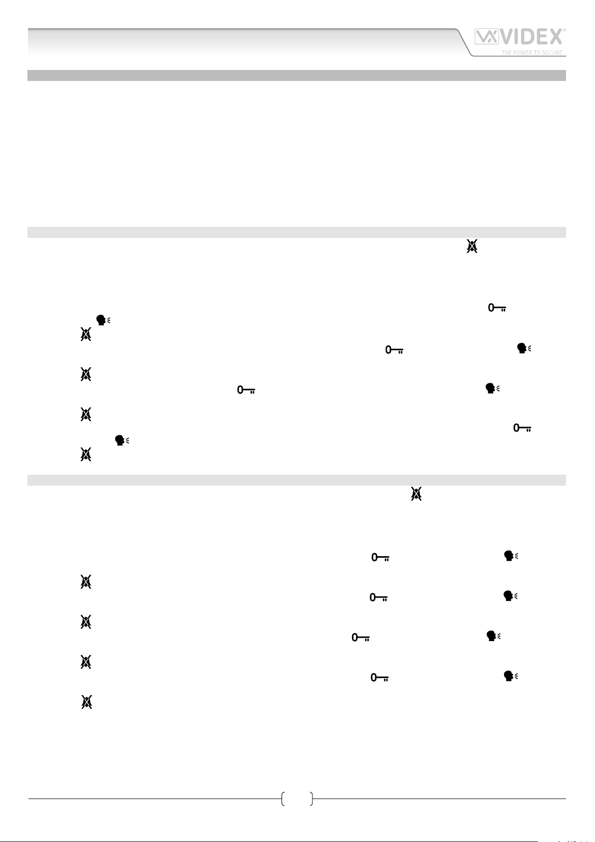
PROGRAMMING AND ADJUSTMENTS
The videomonitor has two dierent menus for programming and adjustment functions:
1. One menu operates when the system is in stand-by and allows to set:
• The privacy duration;
• The melody volume;
• The melody type;
• The number of rings;
2. The second menu operates when the system is turned ON (during a conversation or a camera recall) and allows to set;
• Speech volume;
• Brightness;
• Contrast;
• Hue.
MENÙ 1
• When the system is in stand-by (monitor turned OFF) press and hold pressed (approx 9 seconds) the “
programming menu;
• The OSD menu appears on the display: the top of the screen shows “menu” followed by the available function icons, the bottom
of the screen shows the currently selected function value on the left, the currently selected function icon in the middle and the
next function icon on the right side.
• The rst function available is the privacy duration (max 20 hours): press as many times or hold pressed the “ ” button to increase or the “
• Press the “
• The second function is the melody volume: press as many times or hold pressed the “
to decrease the melody volume level (signalled by a beep).
• Press the “
• The third function is the melody type: press the “
and select the following melody.
• Press the “
• The fourth and last programming function is the number of rings (max 9): press as many times or hold pressed the “ ” button
to increase or the “
• Press the “
” button to decrease the duration of a half an hour each step (signalled by a beep).
” button to store the new value and to enter the following programming function.
” button to increase or the “ ” button
” button to store the new value and to enter the following programming function.
” button to hear and select the previous melody or the “ ” button to hear
” button to store the new value and to enter the following programming function.
” button to decrease the number of rings.
” button to store the new value and exit the programming menu, the monitor turns OFF .
” button to enter the
MENÙ 2
• When the monitor is on during a call is turned ON (conversation or camera recall) press the “
menu.
• The OSD menu appears on the display: the top of the screen shows “menu” followed by the allowed function icons, the bottom
of the screen shows the currently selected function value on the left, the currently selected function icon in the middle and the
next function icon on the right side.
• The rst function is the speech volume: press as many times or hold pressed the “
decrease the speech volume level (signalled by a beep).
• Press the “
• The second function is the brightness: press as many times or hold pressed the “
decrease the brightness level (signalled by a beep).
• Press the “
• The third function is the contrast: press as many times or hold pressed the “
crease the contrast level (signalled by a beep).
• Press the “
• The fourth and last function is the hue: press as many times or hold pressed the “
decrease the hue level (signalled by a beep).
• Press the “
sages for conversation.
” button to store the new value and to enter the following programming function.
” button to store the new value and to enter the following programming function.
” button to store the new value and to enter the following programming function.
” button to store the new value and exit the programming menu the monitor goes back to shown standard mes-
” button to increase or the “ ” button to
” button to increase or the “ ” button to
” button to increase or the “ ” button to de-
” button to increase or the “ ” button to
” button to enter the programming
Art.3678 - Installation instructions
2
66251020-EN - V2.1 - 15/06/16
Page 3
3600 Series
Art.3678 Videophone with hands free facility
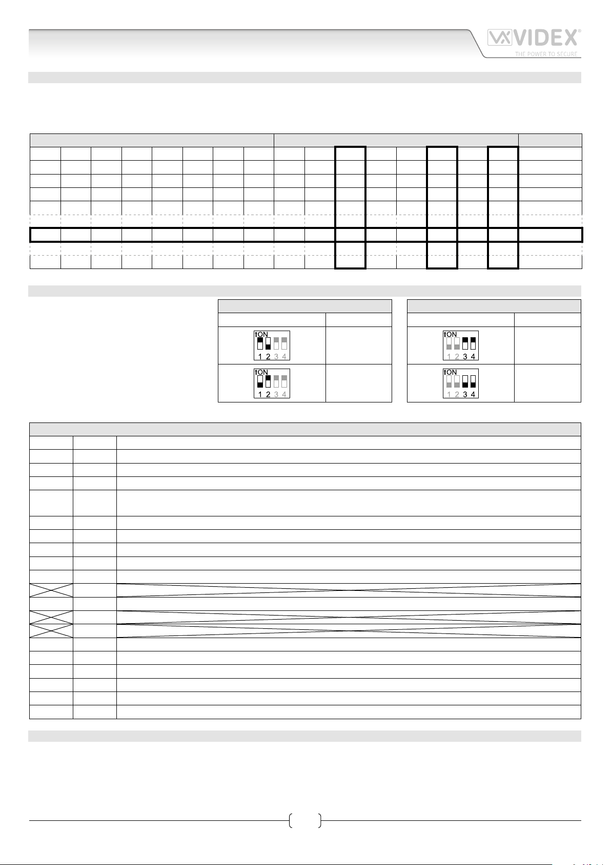
VIDEOMONITOR/INTERCOM ADDRESS, VIDEO MODE AND TERMINATION SETUP
Each intercom is addressed in binary (PHONE ID) using the 8 way dipswitches located on the rear of the unit. Each switch corresponds to one bit which can have a value 0 (OFF) or 1 (ON). Each bit corresponds to a decimal weight depending on the position:
Switch 1 = decimal 1, 2=2, 3=4, 4=8, 5=16, 6=32, 7=64, 8=128. I.E. to set the address 37, put switches 1, 3 and 6 on (1+4+32=37).
SWITCHES DECIMAL WEIGHT ADDRESS
8 7 6 5 4 3 2 1 128 64 32 16 8 4 2 1
OFF OFF OFF OFF OFF OFF OFF ON 0 0 0 0 0 0 0 1 1
OFF OFF OFF OFF OFF OFF ON OFF 0 0 0 0 0 0 1 0 2
OFF OFF OFF OFF OFF OFF ON ON 0 0 0 0 0 0 1 1 3
OFF OFF OFF OFF OFF ON OFF OFF 0 0 0 0 0 1 0 0 4
OFF OFF ON OFF OFF ON OFF ON 0 0 1 0 0 1 0 1 37
ON OFF ON ON OFF ON OFF OFF 1 0 1 1 0 1 0 0 180
TO SET THE VIDEO MODE
The videophone can operate with either composite video signal (coax cable)
or balanced video signal (two wires).
Switches 1 & 2 of SW2 are used to set video mode while switches 3 & 4 are for video termination. When more videophone
have a pass through connection for the
video signal, you must enable the video
termination only for the last videophone.
VIDEO MODE SW2
Switches 1,2 Mode
Coax
Balanced
75 OHM VIDEO TERMINATION SW2
Switches 3,4 Termination
Enabled
Disabled
SIGNALS ON CONNECTION BOARD
+20V 1 Video power supply 17÷20Vdc
+20V 2 Video power supply 17÷20Vdc
GND 3 Video power supply ground reference
GND 4 Video power supply ground reference
V2/V 5
V1 6 Balanced video signal V1 sync. (balanced video signal mode)
L 7 BUS line
GND 8 BUS line ground reference
LB 9 Local bell input (active low)
AL 10 Alarm input (active low)
SB 12 S1 Push button (close to ground when pressed)
+VD 15 +12Vdc output to supply the video distributor Art.894/Art.894N
GND 16 Ground
12VO 17 Stabilized +12Vdc output
12VI 18 +12Vdc Power supply input
LDA 19 Auxiliary LED “1” power supply input
GND 20 Ground
Balanced video signal V2 sync. (balanced video signal mode)
Composite video signal (coax video signal mode)
11
13
14
TECHNICAL SPECIFICATION
Working Voltage: 17÷20Vdc
12÷14Vdc
Power Consumption: Standby: 12mA (on 12Vdc)
Operating: On 12Vdc: 70mA Max
On 20Vdc: 250mA
Working Temperature: -10°C +50°C
Art.3678 - Installation instructions
3
66251020-EN - V2.1 - 15/06/16
Page 4

3600 Series
Art.3678 Videophone with hands free facility
Art.3678 - Installation instructions
4
66251020-EN - V2.1 - 15/06/16
Page 5

3600 Series
224kvd118c.dw
g
Art.3678 Videophone with hands free facility
Local Bell
Local Bell
Art.3678
VIDEX
JP2
+
RELAY
JP1
A
B
Intercom No.
Art.3171
ON
123 4 5 678
L
LB
AL
SW
SW
VR1
3
Art.3678
2x75 ohm
to Art.3678
ON
1 23456 7 8 1 234
ON
BALANCED
Address N.
3
Local Bell
Art.3678
Address N.
13V
ART.521B
115
0
SE
12Vac
ON/OFF
system
1
to Art.3678
Unit ID:
ON
BALANCED
2
ON
21
87
109
653
4
ON
123 4567 8 123 4
Art.506N
5
+B
+
swsw
NO2
4
NC2
3
CO2
2
NO1
NC1
1
C01
SLAVE
Art.4283-0
1C
Art.4843
to Art.3678
ON
1 2 34567 8 1 234
ART.893N1
ON
BALANCED
0
SE
12Vac
ART.521B
MASTER
Art.4283-0
Art.4843
13V
115
0
1C
Address N.
+B
ON/OFF
system
+
swsw
Unit ID:
1
ON
4
21
2
87
109
653
Push to exitPush to exit
Titolo:
Videx Electronics S.p.A.
Via del Lavoro 1, 63846 Monte Giberto (FM)
Phone: +39 0734 631669 - Fax +39 0734 631669
www.videx.it - info@videx.it
Art.3678 - Installation instructions
Notes:
Note:
Data creazione:Title:
12/05/2015
Data modifica:
12/05/2015
Autore:
Roberto Gambini
Cod.File:
Foglio
/ 21
5
66251020-EN - V2.1 - 15/06/16
Page 6

3600 Series
224kvd100.dw
g
Art.3678 Videophone with hands free facility
Art.3676
Address N.
Videophone N. 1
2
VIDEX
ON
1 234567 8 1 234
1
2
3
4
5
6
7
8
9
10
1 2 3 45678
ON
5
11
12
1 2 3 4
R1
ON
13
14
15
16
17
18
Art.3171 or 3172
Phone nr.4
ON
4 5321
6
7
8
S1
to Art.3676
ON
BALANCED
Local Bell
ON
1 2 3
ART.893N1
0
Local BellLocal Bell
to Art.3678
ON
1 234567 8 1 234
ON
BALANCED
ART.521B
1150
+ -
12V
Address N.
sw
sw +
Art.3678
3
+B
Titolo:
L
LB
AL
SW
JP2
RELAY
JP1
A
B
Videx Electronics S.p.A.
Via del Lavoro 1, 63846 Monte Giberto (FM)
Phone: +39 0734 631669 - Fax +39 0734 631669
www.videx.it - info@videx.it
SW
+
VR1
Notes:
Note:
Local Bell
VR4KCMC-N
NC
ON
Coax
SL
V2V1V
SB
VR4KAM2W-0
138
VR4KBM-4
+20
SBSL+12
-
A B C D
1 2 3 456
Data creazione:Title:
23/04/2015
Data modifica:
23/04/2015
Autore:
Marco Rongoni
Cod.File:
SE
12Vac
Foglio
/ 11
Art.3678 - Installation instructions
6
66251020-EN - V2.1 - 15/06/16
Page 7

3600 Series
G
3600 Series Videophone wall mounting instructions
E
C
B
D
A
Fig. 1
H
135cm
C
F
Fig. 2
Fig. 3
CM
N
L
N
M
I
Fig. 4
1. Cables must be fed through the opening E (Fig. 2) of the mounting plate C, which should be tted approximately 135cm from
nished oor level as shown in Fig. 1;
2. Place the mounting plate C against the wall feeding the wire group D through opening E of the mounting plate and mark the
xing holes A (Fig. 2);
3. Drill the xing holes A, insert the wall plugs B then with the cables threaded through opening E x the mounting plate C to the
wall with the 4 screws provided F (Fig. 2);
4. Hook the PBC connection board G to the mounting plate C as shown in Fig. 3 and connect the wires (using the screwdriver
provided) to the terminals as shown in the diagram provided;
5. Once the wires are connected, hook the videophone H to the mounting plate C as shown in Fig. 3;
6. Connect the Plug I on the ribbon cable from the videophone to the plug L on the PCB connection board G;
7. Place the videophone H against the 4 hooks M on the mounting plate C (in line with the 4 openings N on the rear side of the
videophone Fig. 5) and push down as suggested by the pointers in Fig. 4, the videophone will lock into place;
8. To remove the videophone, hold it rmly and push the unit in an upward direction until the videophone H unlocks from the
mounting plate C.
Art.3678 - Installation instructions
Fig. 5
7
66251020-EN - V2.1 - 15/06/16
Page 8

MANUFACTURER
The product is CE marked demonstrating its conformity and is for distribution
VIDEX ELECTRONICS S.P.A.
Via del Lavoro, 1 - 63846 Monte Giberto (FM) Italy
Tel (+39) 0734 631669 - Fax (+39) 0734 632475
www.videx.it - info@videx.it
CUSTOMER SUPPORT
All Countries:
VIDEX ELECTRONICS S.P.A.
www.videx.it - technical@videx.it
Tel: +39 0734-631669 - Fax: +39 0734-632475
UK Customers:
VIDEX SECURITY LTD
www.videx-security.com
Tech Line: 0191 224 3174 - Fax: 0191 224 1559
Main UK oce:
VIDEX SECURITY LTD
1 Osprey Trinity Park
Trinity Way
LONDON E4 8TD
Phone: (+44) 0870 300 1240
Fax: (+44) 020 8523 5825
www.videx-security.com
marketing@videx-security.com
Greece oce:
VIDEX HELLAS Electronics
48 Filolaou Str.
11633 ATHENS
Phone: (+30) 210 7521028
(+30) 210 7521998
Fax: (+30) 210 7560712
www.videx.gr
videx@videx.gr
Northern UK oce:
VIDEX SECURITY LTD
Unit 4-7
Chillingham Industrial Estate
Chapman Street
NEWCASTLE UPON TYNE - NE6 2XX
Tech Line: (+44) 0191 224 3174
Phone: (+44) 0870 300 1240
Fax: (+44) 0191 224 1559
Danish oce:
VIDEX DANMARK
Hammershusgade 15
DK-2100 COPENHAGEN
Phone: (+45) 39 29 80 00
Fax: (+45) 39 27 77 75
www.videx.dk
videx@videx.dk
Benelux oce:
VIDEX BENELUX
E3 Iaan, 93
B-9800 DEINZE
Phone: (+32) 9 380 40 20
Fax: (+32) 9 380 40 25
www.videxbenelux.be
info@videxbenelux.be
within all member states of the EU with no restrictions. This product follows
the provisions of the European Directives 2014/30/EU (EMC); 2014/35/EU
(LVD); 2011/65/EU (RoHS): CE marking 93/68/EEC.
 Loading...