

Page 1
VX 675
3
DEF
2
ABC
1
QZ.
4
GHI
7
PRS
*
5
JKL
8
TUV
0
-SP
X
6
MNO
9
WXY
#
’ ”
’
Reference Guide
C
V
O
E
N
R
F
I
I
F
D
R
O
E
V
E
N
N
S
I
E
T
O
I
IA
E
N
L
3
.
VeriFone Part Number DOC265-004-EN-E, Revision E.3
Page 2

VX 675 Reference Guide
© 2013 VeriFone, Inc.
All rights reserved. No part of the contents of this document may be reproduced or transmitted in any form without the written
permission of VeriFone, Inc.
The information contained in this document is subject to change without notice . Although VeriFone has attempted to ensure the
accuracy of the contents of this document, this document may include errors or omissions. The examples and sample programs are
for illustration only and may not be suited for your purpose. You should verify the applicability of any example or sample p rogram
before placing the software into productive use. This document, including without limitation the examples and software programs, is
supplied “As-Is.”
VeriFone, the VeriFone logo, Omni, VeriCentre, and Verix are registered trademarks of VeriFone. Other brand names or trademarks
associated with VeriFone’s products and services are trademarks of VeriFone, Inc.
All other brand names and trademarks appearing in this manual are the property of their respective holders.
Comments? Please e-mail all comments on this document to your local VeriFone Support Team.
C
V
O
E
N
R
F
I
I
F
D
R
O
E
V
E
N
N
S
I
E
T
O
I
IA
E
N
L
3
.
VeriFone, Inc.
2099 Gateway Place, Suite 600
San Jose, CA, 95110 USA
1-800-VERIFONE
www.verifone.com
VeriFone Part Number DOC265-004-EN-E, Revision E.3
Page 3

CONTENTS
PREFACE . . . . . . . . . . . . . . . . . . . . . . . . . . . . . . . . . . . . . . . 7
Audience. . . . . . . . . . . . . . . . . . . . . . . . . . . . . . . . . . . . . . . . . . . . . . . . . . . . . . . . 7
Organization. . . . . . . . . . . . . . . . . . . . . . . . . . . . . . . . . . . . . . . . . . . . . . . . . . . . . 7
Related Documentation . . . . . . . . . . . . . . . . . . . . . . . . . . . . . . . . . . . . . . . . . . . . 8
Conventions and Acronyms . . . . . . . . . . . . . . . . . . . . . . . . . . . . . . . . . . . . . . . . . 8
Document Conventions. . . . . . . . . . . . . . . . . . . . . . . . . . . . . . . . . . . . . . . . . . 8
Acronym Definitions . . . . . . . . . . . . . . . . . . . . . . . . . . . . . . . . . . . . . . . . . . . 10
CHAPTER 1
Terminal Overview Features at a Glance . . . . . . . . . . . . . . . . . . . . . . . . . . . . . . . . . . . . . . . . . . . . . 12
Features and Benefits . . . . . . . . . . . . . . . . . . . . . . . . . . . . . . . . . . . . . . . . . . . . 12
Exceptional Ease of Use . . . . . . . . . . . . . . . . . . . . . . . . . . . . . . . . . . . . . . . . 12
Performance and Durability . . . . . . . . . . . . . . . . . . . . . . . . . . . . . . . . . . . . . 13
Security. . . . . . . . . . . . . . . . . . . . . . . . . . . . . . . . . . . . . . . . . . . . . . . . . . . . . 13
Communication Technology . . . . . . . . . . . . . . . . . . . . . . . . . . . . . . . . . . . . . 13
F
I
R
CHAPTER 2
Terminal Setup Selecting Terminal Location. . . . . . . . . . . . . . . . . . . . . . . . . . . . . . . . . . . . . . . . 16
Environmental Factors . . . . . . . . . . . . . . . . . . . . . . . . . . . . . . . . . . . . . . . . . 16
Electrical Considerations . . . . . . . . . . . . . . . . . . . . . . . . . . . . . . . . . . . . . . . 16
Unpacking the Shipping Carton . . . . . . . . . . . . . . . . . . . . . . . . . . . . . . . . . . . . . 17
Examining Terminal Features. . . . . . . . . . . . . . . . . . . . . . . . . . . . . . . . . . . . . . . 18
Front Panel . . . . . . . . . . . . . . . . . . . . . . . . . . . . . . . . . . . . . . . . . . . . . . . . . . 18
C
Examining Connection Ports . . . . . . . . . . . . . . . . . . . . . . . . . . . . . . . . . . . . . . . 19
Power Supply . . . . . . . . . . . . . . . . . . . . . . . . . . . . . . . . . . . . . . . . . . . . . . . . 19
Installing the Paper Roll . . . . . . . . . . . . . . . . . . . . . . . . . . . . . . . . . . . . . . . . . . . 20
Installing the SIM Card. . . . . . . . . . . . . . . . . . . . . . . . . . . . . . . . . . . . . . . . . . . . 22
Installing the SD Card. . . . . . . . . . . . . . . . . . . . . . . . . . . . . . . . . . . . . . . . . . . . . 23
Using the Battery . . . . . . . . . . . . . . . . . . . . . . . . . . . . . . . . . . . . . . . . . . . . . . . . 23
Battery Features . . . . . . . . . . . . . . . . . . . . . . . . . . . . . . . . . . . . . . . . . . . . . . 23
Battery Behavior (No Power Pack). . . . . . . . . . . . . . . . . . . . . . . . . . . . . . . . . . . 24
Manual Startup . . . . . . . . . . . . . . . . . . . . . . . . . . . . . . . . . . . . . . . . . . . . . . . 24
Manual Shutdown. . . . . . . . . . . . . . . . . . . . . . . . . . . . . . . . . . . . . . . . . . . . . 24
Connecting the Terminal Power Pack . . . . . . . . . . . . . . . . . . . . . . . . . . . . . . . . 25
Charging the Battery. . . . . . . . . . . . . . . . . . . . . . . . . . . . . . . . . . . . . . . . . . . . . . 26
Battery Life . . . . . . . . . . . . . . . . . . . . . . . . . . . . . . . . . . . . . . . . . . . . . . . . . . 26
Using the VX 675 Base Stations . . . . . . . . . . . . . . . . . . . . . . . . . . . . . . . . . . . . 26
USB Base . . . . . . . . . . . . . . . . . . . . . . . . . . . . . . . . . . . . . . . . . . . . . . . . . . . 26
Full-Feature Base . . . . . . . . . . . . . . . . . . . . . . . . . . . . . . . . . . . . . . . . . . . . . 27
Powering Up the Base . . . . . . . . . . . . . . . . . . . . . . . . . . . . . . . . . . . . . . . . . . . . 27
Docking the Terminal on the Base . . . . . . . . . . . . . . . . . . . . . . . . . . . . . . . . . . . 28
Undocking the Terminal from the Base . . . . . . . . . . . . . . . . . . . . . . . . . . . . . . . 28
Conducting Wireless Transactions. . . . . . . . . . . . . . . . . . . . . . . . . . . . . . . . . . . 28
Conducting Smart Card Transactions . . . . . . . . . . . . . . . . . . . . . . . . . . . . . . . . 29
Using the Magnetic Card Reader. . . . . . . . . . . . . . . . . . . . . . . . . . . . . . . . . . . . 29
Connecting to USB Host. . . . . . . . . . . . . . . . . . . . . . . . . . . . . . . . . . . . . . . . . . . 30
V
E
F
N
O
D
I
O
E
E
R
N
N
I
V
S
E
T
O
I
I
N
A
E
L
3
.
VX 675 REFERENCE GUIDE 3
Page 4

CONTEN TS
VX 675 ECR (Fiscal Module) Support . . . . . . . . . . . . . . . . . . . . . . . . . . . . . . . . 31
Customer Display . . . . . . . . . . . . . . . . . . . . . . . . . . . . . . . . . . . . . . . . . . . . . 31
VX 675 3G and GPS Support. . . . . . . . . . . . . . . . . . . . . . . . . . . . . . . . . . . . . . . 31
GPS Receiver. . . . . . . . . . . . . . . . . . . . . . . . . . . . . . . . . . . . . . . . . . . . . . . . 31
Connecting by 3G. . . . . . . . . . . . . . . . . . . . . . . . . . . . . . . . . . . . . . . . . . . . . 31
CHAPTER 3
Using the Terminal
Keys
CHAPTER 4
Verix Terminal
Manager
V
CHAPTER 5
File Authentication Introduction to File Authentication . . . . . . . . . . . . . . . . . . . . . . . . . . . . . . . . . . . 75
O
C
Data Entry Modes. . . . . . . . . . . . . . . . . . . . . . . . . . . . . . . . . . . . . . . . . . . . . . . . 34
Main Keypad. . . . . . . . . . . . . . . . . . . . . . . . . . . . . . . . . . . . . . . . . . . . . . . . . . . . 34
Command Key Descriptions . . . . . . . . . . . . . . . . . . . . . . . . . . . . . . . . . . . . . 35
When to Use Verix Terminal Manager . . . . . . . . . . . . . . . . . . . . . . . . . . . . . . . . 37
Local and Remote Operations . . . . . . . . . . . . . . . . . . . . . . . . . . . . . . . . . . . . . . 38
Verifying Terminal Status . . . . . . . . . . . . . . . . . . . . . . . . . . . . . . . . . . . . . . . . . . 38
Entering Verix Terminal Manager. . . . . . . . . . . . . . . . . . . . . . . . . . . . . . . . . . . . 38
File Groups. . . . . . . . . . . . . . . . . . . . . . . . . . . . . . . . . . . . . . . . . . . . . . . . . . . . . 39
Passwords . . . . . . . . . . . . . . . . . . . . . . . . . . . . . . . . . . . . . . . . . . . . . . . . . . . . . 39
System Password. . . . . . . . . . . . . . . . . . . . . . . . . . . . . . . . . . . . . . . . . . . . . 40
File Group Passwords. . . . . . . . . . . . . . . . . . . . . . . . . . . . . . . . . . . . . . . . . . 40
Verix Terminal Manager Menus . . . . . . . . . . . . . . . . . . . . . . . . . . . . . . . . . . . . . 40
Verix Terminal Manager Procedures . . . . . . . . . . . . . . . . . . . . . . . . . . . . . . 41
R
Enter and Exit Verix Terminal Manager . . . . . . . . . . . . . . . . . . . . . . . . . . . . 42
E
Menu 1 . . . . . . . . . . . . . . . . . . . . . . . . . . . . . . . . . . . . . . . . . . . . . . . . . . . . . 45
Menu 2 . . . . . . . . . . . . . . . . . . . . . . . . . . . . . . . . . . . . . . . . . . . . . . . . . . . . . 65
F
I
D
I
O
E
N
N
E
T
L
IA
F
N
The VeriFone Certificate Authority . . . . . . . . . . . . . . . . . . . . . . . . . . . . . . . . 75
Special Files Used in the File Authentication Process . . . . . . . . . . . . . . . . . 76
How File Authentication Works. . . . . . . . . . . . . . . . . . . . . . . . . . . . . . . . . . . 77
Planning for File Authentication . . . . . . . . . . . . . . . . . . . . . . . . . . . . . . . . . . 82
Digital Certificates and the File Authentication Process . . . . . . . . . . . . . . . . 85
File Authentication and the File System. . . . . . . . . . . . . . . . . . . . . . . . . . . . . . . 91
VeriShield File Signing Tool . . . . . . . . . . . . . . . . . . . . . . . . . . . . . . . . . . . . . . . . 94
VeriShield File Signing Tool System Requirements . . . . . . . . . . . . . . . . . . . 94
Operating Modes for the VeriShield File Signing Tool . . . . . . . . . . . . . . . . . 94
Command-Line Entries for the File Signing Tool . . . . . . . . . . . . . . . . . . . . . 96
Graphical Interface Mode for the VeriShield File Signing Tool. . . . . . . . . . . 98
E
R
I
V
S
I
O
N
E
.
3
CHAPTER 6
Performing
Downloads
4 VX 675 REFERENCE GUIDE
Downloads and Uploads. . . . . . . . . . . . . . . . . . . . . . . . . . . . . . . . . . . . . . . . . . . 99
Download Methods. . . . . . . . . . . . . . . . . . . . . . . . . . . . . . . . . . . . . . . . . . . . . . . 99
Download Tools . . . . . . . . . . . . . . . . . . . . . . . . . . . . . . . . . . . . . . . . . . . . . . . . 100
Download Content . . . . . . . . . . . . . . . . . . . . . . . . . . . . . . . . . . . . . . . . . . . . . . 100
Full and Partial Downloads. . . . . . . . . . . . . . . . . . . . . . . . . . . . . . . . . . . . . . . . 101
Support for Multiple Applications . . . . . . . . . . . . . . . . . . . . . . . . . . . . . . . . . . . 104
How the File System Supports Multiple Applications . . . . . . . . . . . . . . . . . 104
The Main Application is Always Stored in GID1 . . . . . . . . . . . . . . . . . . . . . 104
Physical and Logical Access to File Groups. . . . . . . . . . . . . . . . . . . . . . . . 105
Use of I: drive and F: drive . . . . . . . . . . . . . . . . . . . . . . . . . . . . . . . . . . . . . . . . 105
Redirection of Files During Application Downloads . . . . . . . . . . . . . . . . . . 106
Page 5

CONTEN TS
Manually Redirecting Files . . . . . . . . . . . . . . . . . . . . . . . . . . . . . . . . . . . . . 106
Redirecting Files to Other File Groups . . . . . . . . . . . . . . . . . . . . . . . . . . . . 107
Restrictions on File Redirection . . . . . . . . . . . . . . . . . . . . . . . . . . . . . . . . . 108
Using DDL.EXE to Automatically Redirect Files. . . . . . . . . . . . . . . . . . . . . 109
File Redirection in Operating System Downloads. . . . . . . . . . . . . . . . . . . . 109
File Redirection in Back-to-Back Application Downloads. . . . . . . . . . . . . . 109
File Authentication Requirements . . . . . . . . . . . . . . . . . . . . . . . . . . . . . . . . . . 110
Required Certificates and Signature Files . . . . . . . . . . . . . . . . . . . . . . . . . 110
The File Authentication Process During an Application Download. . . . . . . 111
File Group Permissions . . . . . . . . . . . . . . . . . . . . . . . . . . . . . . . . . . . . . . . 113
Download an Operating System Update Provided by VeriFone. . . . . . . . . 114
File Authentication for Back-to-Back Application Downloads. . . . . . . . . . . 115
Timing Considerations Due to the Authentication Process. . . . . . . . . . . . . 116
Support for File Compression. . . . . . . . . . . . . . . . . . . . . . . . . . . . . . . . . . . 116
Effect of Downloads on Existing Files and Data. . . . . . . . . . . . . . . . . . . . . . . . 117
Direct Application Downloads. . . . . . . . . . . . . . . . . . . . . . . . . . . . . . . . . . . 118
Hardware Checklist. . . . . . . . . . . . . . . . . . . . . . . . . . . . . . . . . . . . . . . . . . . 118
N
N
V
O
Software Checklist . . . . . . . . . . . . . . . . . . . . . . . . . . . . . . . . . . . . . . . . . . . 118
Checklist for Effects on Files and Settings in the Receiving Terminal . . . . 118
Direct Application Download Procedure . . . . . . . . . . . . . . . . . . . . . . . . . . . 119
Direct Operating System Downloads . . . . . . . . . . . . . . . . . . . . . . . . . . . . . . . . 126
Hardware Checklist. . . . . . . . . . . . . . . . . . . . . . . . . . . . . . . . . . . . . . . . . . . 126
R
Software Checklist . . . . . . . . . . . . . . . . . . . . . . . . . . . . . . . . . . . . . . . . . . . 126
Checklist for Effects on Files and Settings in the Receiving Terminal . . . . 126
E
Direct Operating System Download Procedure . . . . . . . . . . . . . . . . . . . . . 127
Back-to-Back Application Downloads. . . . . . . . . . . . . . . . . . . . . . . . . . . . . . . . 131
N
F
Hardware Checklist. . . . . . . . . . . . . . . . . . . . . . . . . . . . . . . . . . . . . . . . . . . 131
Software Checklist . . . . . . . . . . . . . . . . . . . . . . . . . . . . . . . . . . . . . . . . . . . 131
Checklist for Effects on Files and Settings in the Receiving Terminal . . . . 132
Back-to-Back Application Download Procedure. . . . . . . . . . . . . . . . . . . . . 132
F
I
D
I
O
E
C
CHAPTER 7
Specifications Power . . . . . . . . . . . . . . . . . . . . . . . . . . . . . . . . . . . . . . . . . . . . . . . . . . . . . . . . 137
Micro-USB Power Pack . . . . . . . . . . . . . . . . . . . . . . . . . . . . . . . . . . . . . . . . . . 137
Temperature. . . . . . . . . . . . . . . . . . . . . . . . . . . . . . . . . . . . . . . . . . . . . . . . . . . 137
External Dimensions . . . . . . . . . . . . . . . . . . . . . . . . . . . . . . . . . . . . . . . . . . . . 137
E
R
I
V
S
E
T
O
I
IA
E
N
L
3
.
CHAPTER 8
Maintenance Cleaning the Terminal . . . . . . . . . . . . . . . . . . . . . . . . . . . . . . . . . . . . . . . . . . . 139
Terminal Contacts . . . . . . . . . . . . . . . . . . . . . . . . . . . . . . . . . . . . . . . . . . . . . . 139
Smart Card Reader . . . . . . . . . . . . . . . . . . . . . . . . . . . . . . . . . . . . . . . . . . . . . 139
CHAPTER 9
VeriFone Service
and Support
Returning a Terminal for Service . . . . . . . . . . . . . . . . . . . . . . . . . . . . . . . . . . . 141
Accessories and Documentation . . . . . . . . . . . . . . . . . . . . . . . . . . . . . . . . . . . 142
Power Pack. . . . . . . . . . . . . . . . . . . . . . . . . . . . . . . . . . . . . . . . . . . . . . . . . 142
Printer Paper. . . . . . . . . . . . . . . . . . . . . . . . . . . . . . . . . . . . . . . . . . . . . . . . 142
VeriFone Cleaning Kit. . . . . . . . . . . . . . . . . . . . . . . . . . . . . . . . . . . . . . . . . 142
Micro-USB Cable . . . . . . . . . . . . . . . . . . . . . . . . . . . . . . . . . . . . . . . . . . . . 143
Documentation . . . . . . . . . . . . . . . . . . . . . . . . . . . . . . . . . . . . . . . . . . . . . . 143
VX 675 REFERENCE GUIDE 5
Page 6

CONTEN TS
System Messages Error Messages . . . . . . . . . . . . . . . . . . . . . . . . . . . . . . . . . . . . . . . . . . . . . . . . 145
APPENDIX A
Information Messages . . . . . . . . . . . . . . . . . . . . . . . . . . . . . . . . . . . . . . . . . . . 153
APPENDIX B
Troubleshooting
Guidelines
APPENDIX C
Port Pinouts Micro-USB Port. . . . . . . . . . . . . . . . . . . . . . . . . . . . . . . . . . . . . . . . . . . . . . . . . 167
APPENDIX D
ASCII Table The ASCII Table. . . . . . . . . . . . . . . . . . . . . . . . . . . . . . . . . . . . . . . . . . . . . . . . 169
V
Terminal Does Not Start. . . . . . . . . . . . . . . . . . . . . . . . . . . . . . . . . . . . . . . . . . 163
Terminal Display Does Not Show Correct/Readable Info. . . . . . . . . . . . . . . . . 163
Battery Does Not Charge . . . . . . . . . . . . . . . . . . . . . . . . . . . . . . . . . . . . . . . . . 164
Blank Display . . . . . . . . . . . . . . . . . . . . . . . . . . . . . . . . . . . . . . . . . . . . . . . . . . 164
Printer Does Not Print. . . . . . . . . . . . . . . . . . . . . . . . . . . . . . . . . . . . . . . . . . . . 164
Printer Paper Jam. . . . . . . . . . . . . . . . . . . . . . . . . . . . . . . . . . . . . . . . . . . . . . . 165
Keypad Does Not Respond . . . . . . . . . . . . . . . . . . . . . . . . . . . . . . . . . . . . . . . 165
Transactions Fail to Process . . . . . . . . . . . . . . . . . . . . . . . . . . . . . . . . . . . . . . 165
E
RS-232 Port
(FFB only). . . . . . . . . . . . . . . . . . . . . . . . . . . . . . . . . . . . . . . . . . . . . . . . . . . . . 167
Telco Port
(FFB only). . . . . . . . . . . . . . . . . . . . . . . . . . . . . . . . . . . . . . . . . . . . . . . . . . . . . 168
Ethernet Port (FFB only). . . . . . . . . . . . . . . . . . . . . . . . . . . . . . . . . . . . . . . . . . 168
USB Host Port (FFB and USB base) . . . . . . . . . . . . . . . . . . . . . . . . . . . . . . . . 168
R
E
F
I
D
I
O
E
N
IA
T
N
L
F
APPENDIX E
VX 675 Battery
Information
O
C
N
.
3
Battery . . . . . . . . . . . . . . . . . . . . . . . . . . . . . . . . . . . . . . . . . . . . . . . . . . . . . . . 171
Charging . . . . . . . . . . . . . . . . . . . . . . . . . . . . . . . . . . . . . . . . . . . . . . . . . . . 171
Battery Life . . . . . . . . . . . . . . . . . . . . . . . . . . . . . . . . . . . . . . . . . . . . . . . . . 171
Advantages. . . . . . . . . . . . . . . . . . . . . . . . . . . . . . . . . . . . . . . . . . . . . . . . . 171
Precautions. . . . . . . . . . . . . . . . . . . . . . . . . . . . . . . . . . . . . . . . . . . . . . . . . 172
Notable VX 675 Battery Specifications. . . . . . . . . . . . . . . . . . . . . . . . . . . . . . . 173
Safety/Protection Circuit . . . . . . . . . . . . . . . . . . . . . . . . . . . . . . . . . . . . . . . 173
Cell Temperature Monitoring . . . . . . . . . . . . . . . . . . . . . . . . . . . . . . . . . . . 173
ESD Protection . . . . . . . . . . . . . . . . . . . . . . . . . . . . . . . . . . . . . . . . . . . . . . 173
Trip Recovery . . . . . . . . . . . . . . . . . . . . . . . . . . . . . . . . . . . . . . . . . . . . . . . 174
Battery FAQs (for VX 675) . . . . . . . . . . . . . . . . . . . . . . . . . . . . . . . . . . . . . . . . 174
VX 675 Battery Specific Terms and Definitions . . . . . . . . . . . . . . . . . . . . . . . . 175
General Battery Terms and Definitions . . . . . . . . . . . . . . . . . . . . . . . . . . . . . . 175
GLOSSARY . . . . . . . . . . . . . . . . . . . . . . . . . . . . . . . . . . . . . 179
INDEX . . . . . . . . . . . . . . . . . . . . . . . . . . . . . . . . . . . . . . . . 185
E
R
I
V
S
I
O
N
E
6 VX 675 REFERENCE GUIDE
Page 7

PREFACE
This guide is your primary source of information for setting up and installing the
VX 675 terminal.
Audience
Organization
This guide is useful for anyone installing and configuring a VX 675 terminal. Basic
descriptions of the terminal features are also provided.
This guide is organized as follows:
Chapter 1, Terminal Overview. Provides an overview of the VX 675 terminal.
Chapter 2, Terminal Setup. Explains how to set up and install the VX 675 terminal.
Provides information on how to select a location, establish power, and how to
configure optional peripheral devices.
Chapter 3, Using the Terminal Keys. Explains how to set up and install the VX 675
terminal. It tells you how to select a location, establish power, and how to
configure optional peripheral devices.
Chapter 4, Verix Terminal Manager. Describes password-controlled, Verix
Terminal Manager operations, as well as how to use it to perform a variety of test
and configuration procedures.
Chapter 5, File Authentication.Describes the file authentication module of the
VeriShield security architecture and describes how to use the file signing utility,
VeriShield File Signing Tool, to generate signature files.
Chapter 6, Performing Downloads. Documents procedures for downloading
applications and files to VX 675 units.
Chapter 7, Specifications. Explains how to maintain your VX 675 terminal.
Chapter 8, Maintenance. Discusses the power requirements and dimensions of
the VX 675 terminal.
Chapter 9, VeriFone Service and Support. Provides information on contacting
your local VeriFone representative or service provider, and information on how to
order accessories or documentation from VeriFone.
Appendix A, System Messages. Provides description about error and information
messages, which are grouped into two categories.
Appendix B, Troubleshooting Guidelines. Provides information to help you install
and configure your VX 675 terminal successfully.
Appendix C, Port Pinouts. Provides list of pinouts for the VX 675 terminal,
dongles, and cable connectors.
Appendix D, ASCII Table. Provides an ASCII table.
VX 675 REFERENCE GUIDE 7
Page 8

PREFACE
Related Documentation
Appendix E, VX 675 Battery Information. Provides information about the VX 675
Smart Battery.
Related
Documentation
Conventions and
Acronyms
To learn more about the VX 675 terminal, refer to the following set of documents:
VX 675 Certifications and Regulations Sheet VPN DOC265-001-EN
VX 675 Quick Installation Guide VPN DOC265-002-EN
VX 675 Installation Guide VPN DOC265-003-EN
VX 675 Base Certifications and Regulations
Sheet
VX 675 Full-Featured Base Quick Installation
Guide
VX 675 USB Base Quick Installation Guide VPN DOC265-025-EN
VX 675 ECR Certifications and Regulations Sheet VPN DOC265-027-EN
VX 675 ECR Quick Installation Guide VPN DOC265-028-EN
Verix eVo Volume I: Operating System
Programmers Manual
Verix eVo Volume II: Operating System and
Communications Programmers Guide
VPN DOC265-005-EN
VPN DOC265-026-EN
VPN DOC00301
VPN DOC00302
This section describes conventions and acronyms used in this manual.
Document
Conventions
V arious conventions are used to help you quickly identify special formatting. Table
1 describes these conventions and provides examples of their use.
Table 1 Document Conventions
Convention Meaning Example
Blue Text in blue indicates terms that
are cross referenced.
Italics Italic typeface indicates book
titles or emphasis.
Courier The courier typeface is used
while specifying onscreen text,
such as text that you would enter
at a command prompt, or to
provide an URL.
See Conventions and Acronyms.
You must install a roll of thermalsensitive paper in the printer.
RetrieveClearCardData
retrieves the previous swipe's
clear track data and places it into
the
pstSwipeOut argument.
8 VX 675 REFERENCE GUIDE
Page 9
Table 1 Document Conventions
NOTE
CAUTION
WARNING
Convention Meaning Example
PREFACE
Conventions and Acronyms
The pencil icon is used to
highlight important information.
The caution symbol indicates
possible hardware or software
failure, or loss of data.
The lighting symbol is used as a
warning when bodily injury might
occur.
RS-232-type devices do not work
with the PINpad port.
The terminal is not waterproof or
dustproof, and is intended for
indoor use only.
Due to risk of shock do not use
the terminal near water.
VX 675 R
EFERENCE GUIDE 9
Page 10

PREFACE
Conventions and Acronyms
Acronym Definitions
Various acronyms are used in place of the full definition. Table 2 presents
acronyms and their definitions.
Table 2 Acronym Definitions
Acronym Definitions
AC Alternating Current
A-GPS Assisted GPS
ECR Electronic Cash Registers
EMV Europay MasterCard and VISA
GPRS General Packet Radio Service
GPS Global Positioning System
GSM Global System for Mobile Communication
HDMI High-Definition Multimedia Interface
HSPA High Speed Packet Access
ITP Internal Thermal Printer
LCD Liquid Crystal Display
LED Light Emitting Diode
MRA Merchandise Return Authorization
MSAM Micromodule-Size Security Access Module
PED PIN Entry Device
PIN Personal Identification Number
QVGA Quarter Video Graphics Array
RJ45 Registered Jack 45
RS-232 Recommended Standard 232
R-UIM Removable User Identity Module
SAM Security Access Module
SD Secure Digital
SIM Subscriber Identity Module
TFT Thin Film Transistor
UART Universal Asynchronous Transmitter/Receiver
UMTS Universal Mobile Telecommunications System
10 VX 675 REFERENCE GUIDE
USB Universal Serial Bus
VPN VeriFone Part Number
Page 11
Terminal Overview
NOTE
3
DEF
2
ABC
1
QZ.
4
GHI
7
PRS
*
5
JKL
8
TUV
0
-SP
X
6
MNO
9
WXY
#
’ ”
’
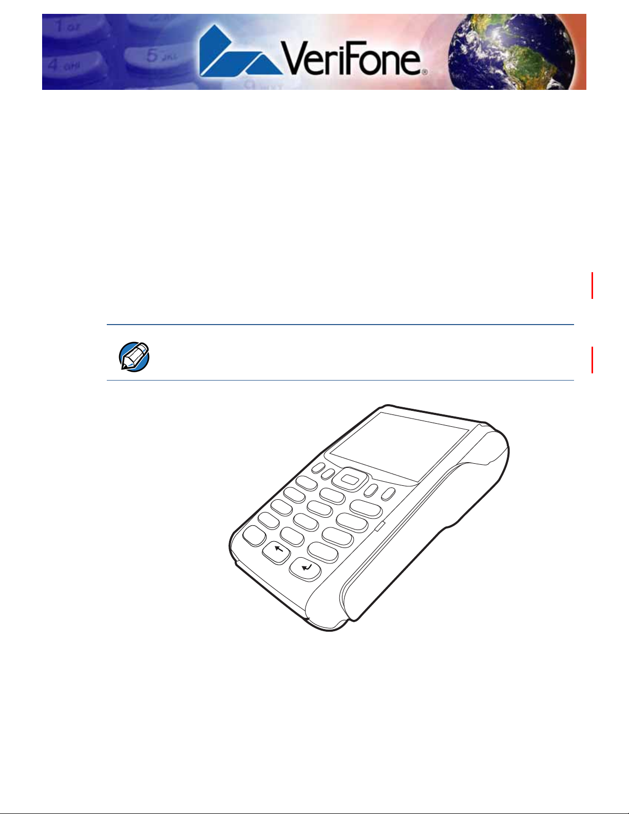
This chapter provides a brief description of the VX 675 terminal. This terminal
features a color screen display, fast processor, abundant memory, and PCI 3.0
security.
The VX 675 terminal is a portable, battery-powered device designed to fit
comfortably during handheld consumer-facing applications. It features a 2.8” TFT
LCD display and a backlit spill-resistant keypad. It supports the 3G universal
mobile telecommunications system (UMTS), GPS / A-GPS, and GPRS
communications technology.
VeriFone sh ips varian ts of the VX 675 terminal for different markets. Your terminal
may have a different configuration—VX 675 3G supports dual SIM slots and micro
SD card, VX 675 with ECR functionality is specific only to Turkey market.
CHAPTER 1
Figure 1 VX 675 Terminal
VX 675 REFERENCE GUIDE 11
Page 12

TERMINAL OVERVIEW
Features at a Glance
Features at a
Glance
Features and
Benefits
The following are the features of VX 675:
• 400 MHz ARM11 RISC processor
delivers power and usability in a
convenient “hand-over” design.
• Multi-application operating
environment.
• Advanced memory architecture to
meet tomorrow’s needs with support
for 192 MB.
• Backward compatibility with VeriFone
solutions help reduces development
costs.
• Drop-resistant design minimizes
breakage.
• 32-bit processing and multi-tasking
capabilities.
• Security architecture exceeds
specifications for PCI-PED and
sophisticated file authentication.
• Securely supports and runs payment
and value-added applications along
with signature capture.
• Offers unsurpassed performance on
EMV smart card transactions
• Max UI design provides large 2.8” color
LCD display , and lar ge blue backlit keys
for easier viewing.
• Adds vibrant color screen to the
smallest purpose-built wireless payment
device.
• Multiple connectivity options.
• Spill-resistant design forces liquid down
and off the front of the terminal.
VX 675 terminals provide the right combination of features and functions including
a triple-track magnetic stripe card reader , supports the “mini-format” cards, Hi/Low
coercivity cards, micro SD cards, smart card reader, one or two SAMs, integrated
PIN pad, color screen display, and a quiet yet fast internal thermal printer (ITP).
Exceptional Ease of
Use
• Lightweight, tapered design, compact, stylish and the ergonomic balance
allows convenient terminal hand-off to the consumer for PIN entry or other
input.
• 2.8” TFT LCD display for boundless application possibilities and easy
readability under various lighting conditions.
• Large, blue backlit keys provide tactile response to simplify usage and
minimize finger slips.
• 25mm (VX 675 GPRS) and 40mm diameter paper roll support with a trouble-
free, drop-in, “clam shell” loading and dual tear bar that allow receipts to be
torn in any direction.
• Quiet and fast integrated thermal printer (25 LPS with a fully charged battery)
with Out-of-Paper sensor.
• Vertical magnetic stripe card reader with an extended blade for optimal card
reading.
12 VX 675 REFERENCE GUIDE
Page 13

TERMINAL OVERVIEW
Features and Benefits
Performance and
Durability
Security
Communication
Technology
• Fast transactions due to powerful 400 MHz ARM11 processor.
• High-capacity 3.6 V 2200 mAh Li-ion battery. VX 675 3G supports 3.7 V 2200
mAh Li-ion battery pack.
• Base for drop-and-go charging.
• Rounded corners and drop resistant to 3 feet on concrete floor to minimize
breakage.
• 192 MB of memory.
• PCI PED 3.0 approved for debit and other PIN-based transactions.
• EMV Level 1 and 2 Type Approval.
• Tamper-resistant construction, SSL protocols, and VeriShield file
authentication.
• VX 675 GPRS and VX 675 3G: Long-range wireless payment for retailers that
have no physical location limitations.
• VX 675 WiFi-BT: Ideal for retailers that need multiple wireless devices and
have existing IP infrastructure. It also offers simple, plug-and-play installation
for locations that need short-range wireless capability.
VX 675 R
EFERENCE GUIDE 13
Page 14

TERMINAL OVERVIEW
Features and Benefits
14 VX 675 REFERENCE GUIDE
Page 15

Terminal Setup
CHAPTER 2
This chapter describes terminal setup procedures. You will learn about:
• Selecting Terminal Location
• Unpacking the Shipping Carton
• Examining Terminal Features
• Examining Connection Ports
• Installing the Paper Roll
• Installing the SIM Card
• Installing the SD Card
• Using the Battery
• Battery Behavior (No Power Pack)
• Charging the Battery
• Connecting the Terminal Power Pack
• Using the VX 675 Base Stations
• Docking the Terminal on the Base
• Undocking the Terminal from the Base
• Conducting Wireless Transactions
• Conducting Smart Card Transactions
• Using the Magnetic Card Reader
• Connecting to USB Host
• VX 675 ECR (Fiscal Module) Support
• VX 675 3G and GPS Support
VX 675 REFERENCE GUIDE 15
Page 16

TERMINAL SETUP
CAUTION
Selecting Terminal Location
Selecting
Terminal
Location
Environmental
Factors
Electrical
Considerations
Use the following guidelines when selecting a location for your VX 675 terminal.
• The VX 675 unit is a portable terminal. Select a flat support surface, such as a
countertop or table, to keep the terminal safe in between uses.
• Do not use the terminal where there is high heat, dust, humidity, moisture, or
caustic chemicals or oils.
• Keep the terminal away from direct sunlight and anything that radiates heat,
such as a stove or motor.
• Do not use the terminal outdoors.
The terminal is not waterproof or dustproof, and is intended for indoor use only.
Any damage to the unit from exposure to rain or dust may void any warranty.
• Avoid using this product during electrical storms.
• Avoid locations near electrical appliances or other devices that cause
excessive voltage fluctuations or emit electrical noise (for example, air
conditioners, electric motors, neon signs, high-frequency or magnetic security
devices, or computer equipment).
• Do not use the terminal near water or in moist conditions.
16 VX 675 REFERENCE GUIDE
Page 17
TERMINAL SETUP
CAUTION
Unpacking the Shipping Carton
Unpacking the
Shipping Carton
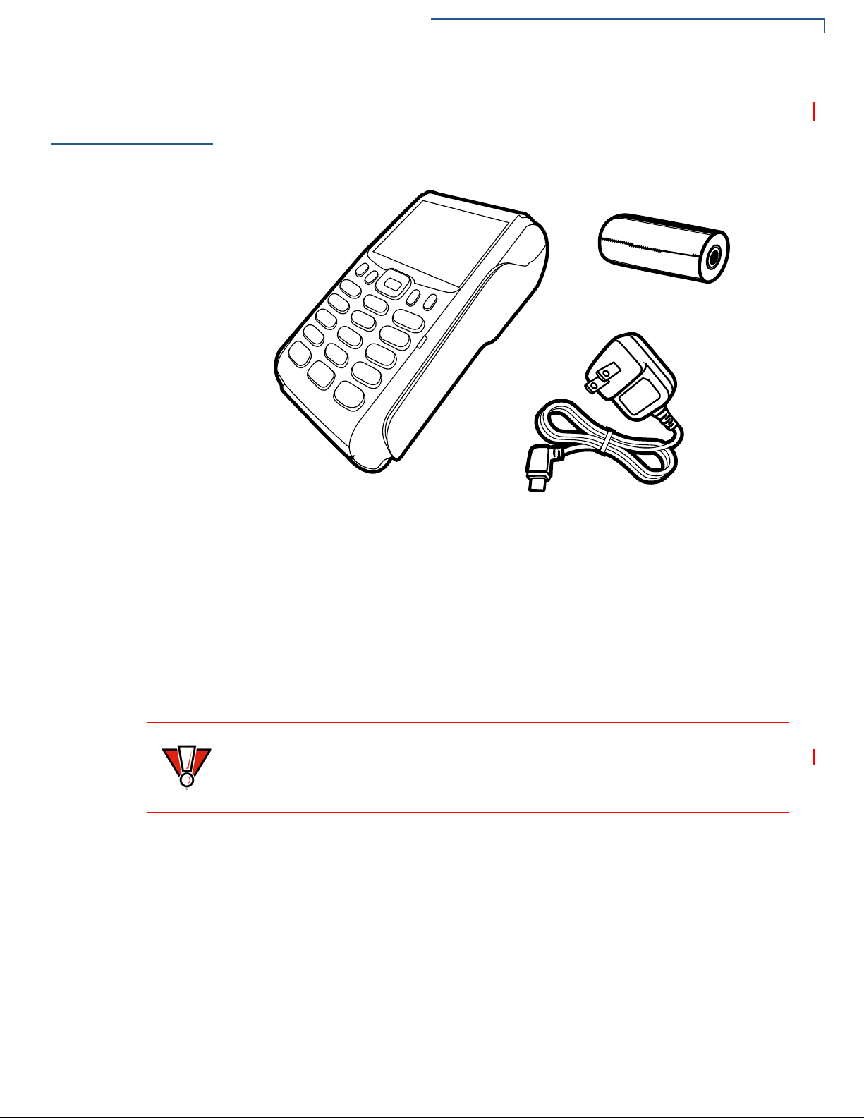
Open the shipping carton and carefully inspect its conten ts for possible t ampering
or shipping damage. The VX 675 device is a secure product and any tampering
may cause the terminal to cease to function properly.
Figure 2 VX 675 Shipping Carton Contents
To unpack the
Shipping Carton
1 Remove and inspect the following items:
• Terminal
• Power pack
• Paper roll
2 Remove all plastic wrapping from the terminal and other components.
3 Remove the clear protective film from the LCD screen.
Do not use a terminal that has been damaged or tampered with. The
terminal comes equipped with tamper-evident labels. If a label or component
appears damaged, please notify the shipping company and your VeriFone
representative or service provider immediately.
4 Save the shipping carton and packing material for future repacking or moving
the terminal.
VX 675 R
EFERENCE GUIDE 17
Page 18
TERMINAL SETUP
Examining Terminal Features
Examining
Terminal
Features
Before you continue the installation process, see the terminal features illustrated
below.
Front Panel
18 VX 675 REFERENCE GUIDE
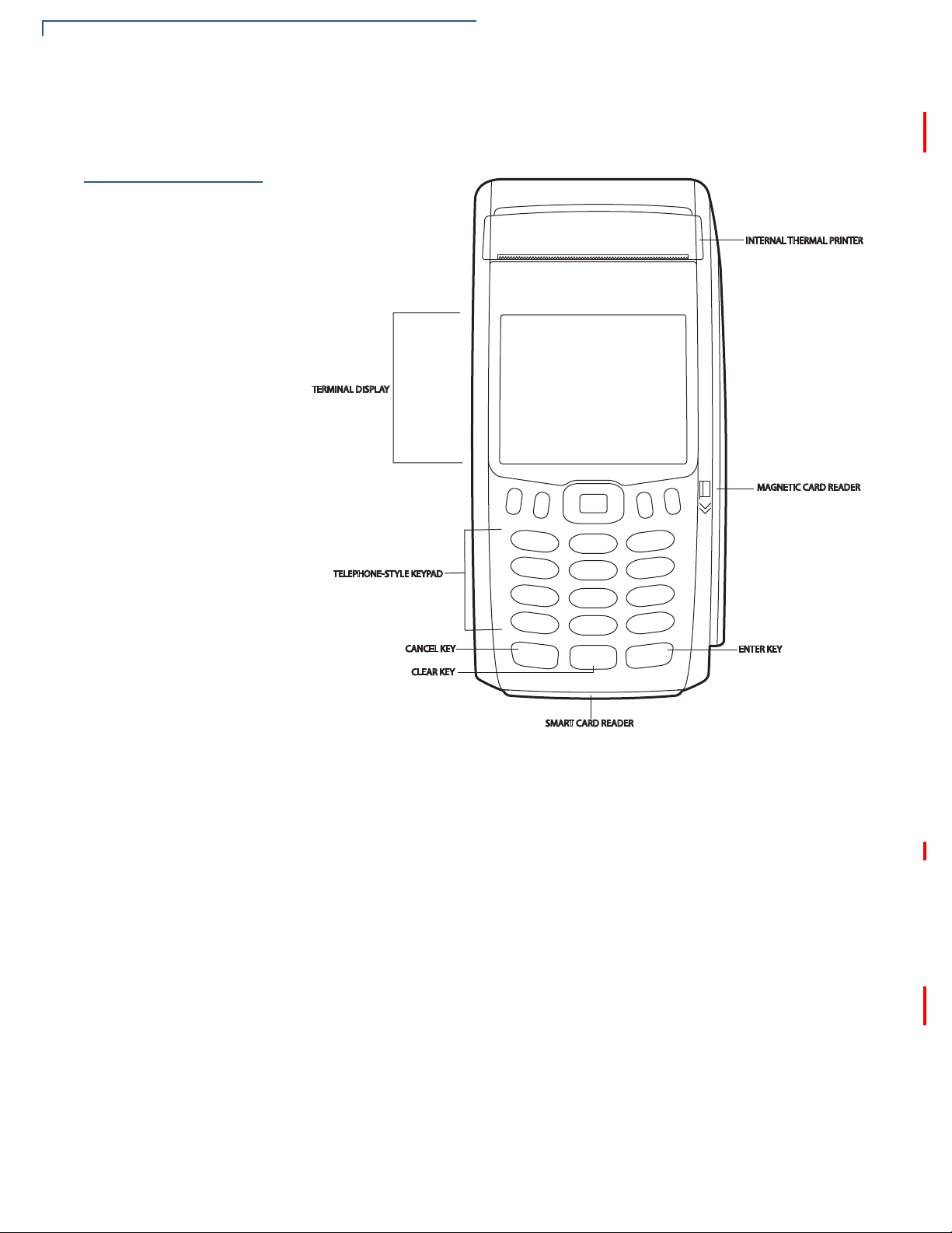
Figure 3 VX 675 Terminal Features (Front Panel)
The front panel includes the following features:
• A 2.8” TFT LCD display.
• A set of keys that include:
a A 12-key, telephone-style keypad (keypads may vary in style).
b Three color-coded function keys below the keypad (from left to right:
CANCEL, CLEAR, ENTER).
c Four function keys below the display (PF1, PF2, PF3, PF4) and a five-way
navigational key in the middle.
• A magnetic card reader, built into the right side. Swipe the card using the
proper direction, with the magnetic stripe down and facing inward, toward the
keypad.
• An internal thermal printer at the top front of the terminal.
Page 19
TERMINAL SETUP
NOTE
Examining Connection Ports
• A smart card reader, built into the bottom of the terminal. For directions on
how to use a smart card, see Conducting Smart Card Transactions.
• A SAM (security access module) compartment, built into the bottom of the
terminal inside the back compartment. The VX 675 terminal contains an
MSAM cardholder to support stored-value card programs or other merchant
card requirements.
VeriFon e ship s variants of the VX 675 terminal for different market s. Your terminal
may have a different configuration. However , the basic processes described in this
guide remain the same, regardless of terminal configuration.
Examining
Connection
Ports
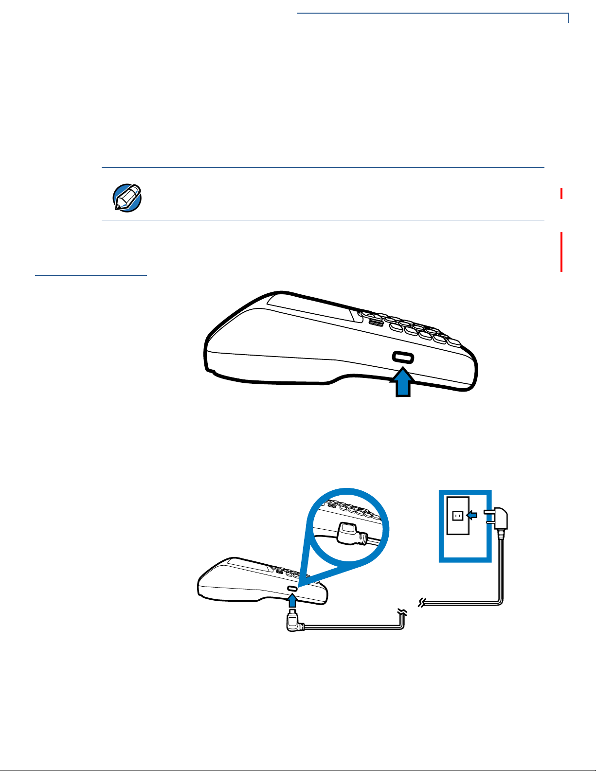
Power Supply
The VX 675 terminal has one primary micro-USB port.
VX 675 3G and VX 675 WiFi-BT supports USB Host function via primary microUSB port.
Figure 4 VX 675 Primary Micro-USB Port
Each VX 675 terminal comes with power supply (VPN PWR265-001-01-A) used
to connect the terminal directly to a power outlet and to charge the battery.
Figure 5 Power Supply Connection to a VX 675 Terminal
VX 675 R
EFERENCE GUIDE 19
Page 20
TERMINAL SETUP
CAUTION
%
$
%
$
Installing the Paper Roll
Installing the
Paper Roll
To Install a Paper Roll
A fast, quiet thermal printer is built into the VX 675 terminal. Before you can
process transactions that require a receipt or record, you must install a roll of
thermal-sensitive paper in the printer.
The ITP uses a roll of single-ply, thermal-sensitive paper: 25mm and 40mm. A
pink out-of-paper indicator line appears on the edge of the paper approximately
18 inches before the end of the roll. After this line appears, th ere is enoug h paper
remaining on the roll to conclude at least one transaction.
Poor-quality paper can jam the printer and create excessive paper dust. To order
high-quality VeriFone paper, refer to Accessories and Documentation.
Store thermal paper in a dry, dark area. Handle thermal paper carefully: impact,
friction, temperature, humidity, and oils affect the color and storage
characteristics of the paper.
Never load a roll of paper with folds, wrinkles, tears, or holes at the edges in the
print area.
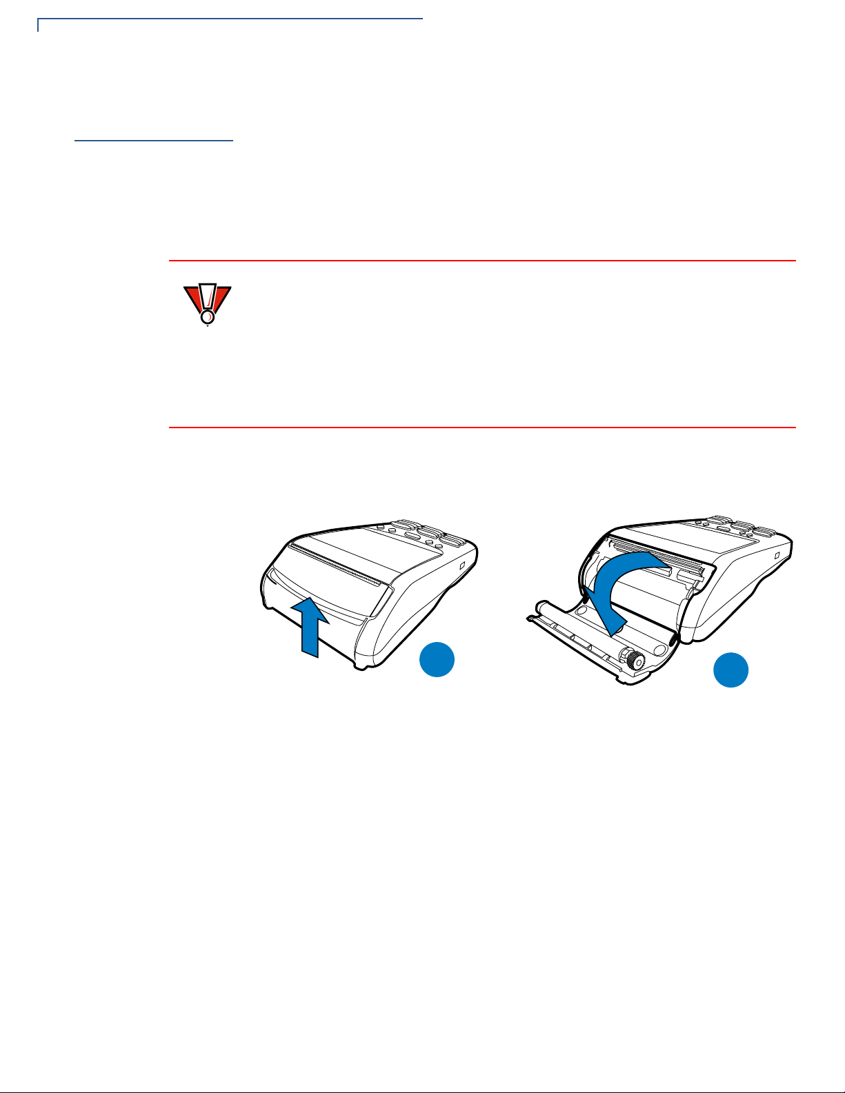
1 Gently pull the latch located on the bottom of the terminal to unlock the paper
roll cover.
20 VX 675 REFERENCE GUIDE
Figure 6 Unlocking the Printer Cover
2 Lift the printer cover up and back.
3 Remove any partial roll of paper in the printer tray.
4 Loosen the glued leading edge of the new roll of paper or remove the
protective strip, if applicable. Unwind the paper roll past any glue residue.
5 Hold the roll so the paper feeds from the bottom of the roll when the terminal is
inverted (see illustration below).
Page 21
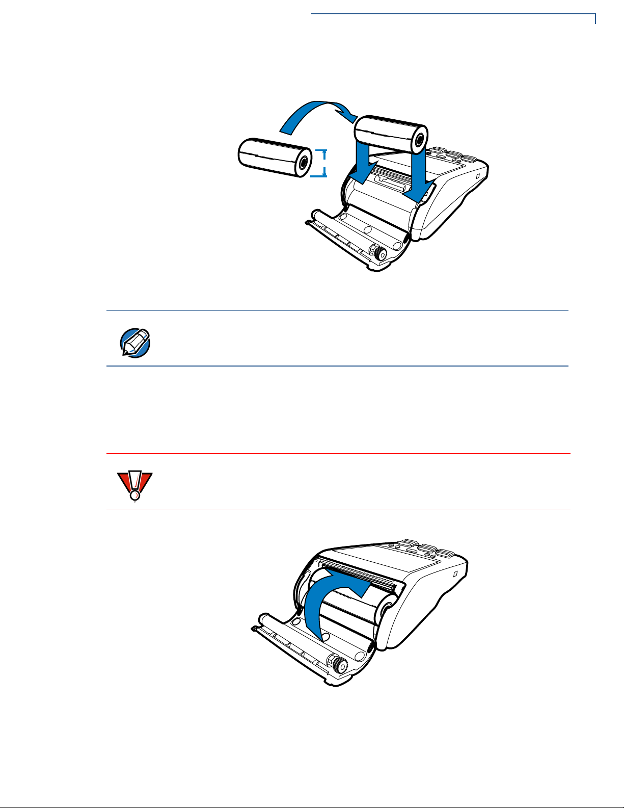
6 Drop the paper roll into the printer tray.
PP
NOTE
CAUTION
Figure 7 Loading Paper Roll
TERMINAL SETUP
Installing the Paper Roll
VX 675 with ECR functionality uses 40mm paper roll.
7 Pull paper up past the glue residue on the paper roll.
8 Close the paper roll cover by gently pressing directly on the cover until it clicks
shut, allowing a small amount of paper p ast the glue residue to extend out side
the printer door.
To prevent damaging the print roller, always gently press down on the paper roll
cover to close it.
Figure 8 Closing Paper Roll Cover
9 Tear the paper off against the serrated plastic strip in the printer.
VX 675 R
EFERENCE GUIDE 21
Page 22
TERMINAL SETUP
%
$
NOTE
'&
0,
6
0
,6
$
%
Installing the SIM Card
Installing the
SIM Card
To install or replace
the card
The VX 675 terminal for GPRS modems supports the installation of a GSM SIM
(Subscriber Identity Module). Use the following procedure to install a SIM card.
1 Turn off the terminal.
2 Place the terminal upside down on a soft, clean surface to protect the lens
from scratches.
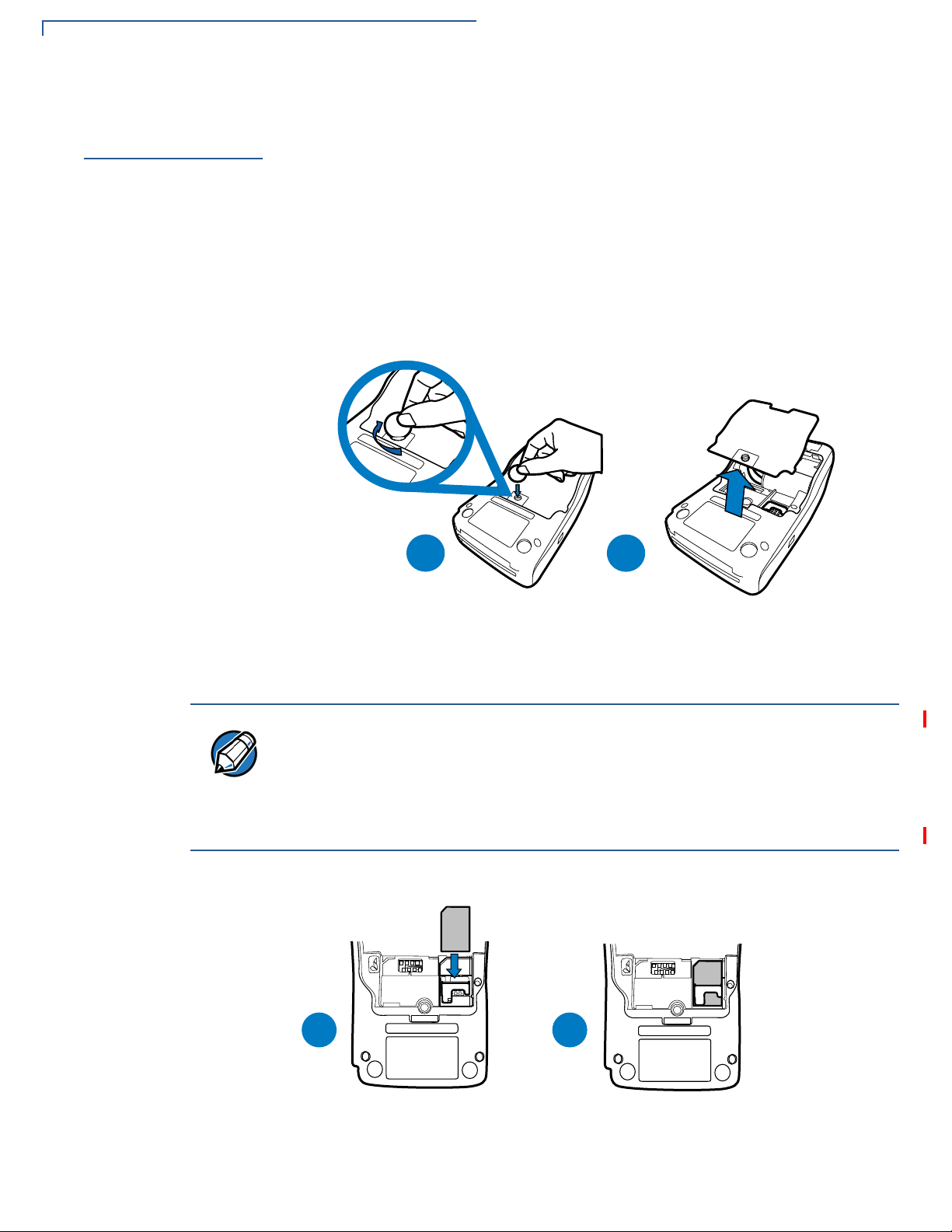
3 Unscrew and remove the back compartment cover.
4 Lift the battery pack.
Figure 9 Removing the Back Compartment Cover
5 Insert the SIM card into the cardholder.
There is only one SIM slot (VX 675 3G has dual SIM support). Before inserting
the SIM card, position it as shown in in the illustration below, with the card’s gold
contacts facing the compartment. The cardholder connector base has a set of
contacts and a notch to ensure the SIM/R-UIM card is positioned correctly. The
SIM card has a notch on one corner to ensure that it fit s into the connector base in
only one way.
22 VX 675 REFERENCE GUIDE
Figure 10 Inserting the SIM Card
Page 23
6 Return the battery pack to its original position.
$
%
NOTE
7 Close and screw the back compartment cover.
TERMINAL SETUP
Installing the SD Card
Installing the SD
Card
To install or replace
the SD card:
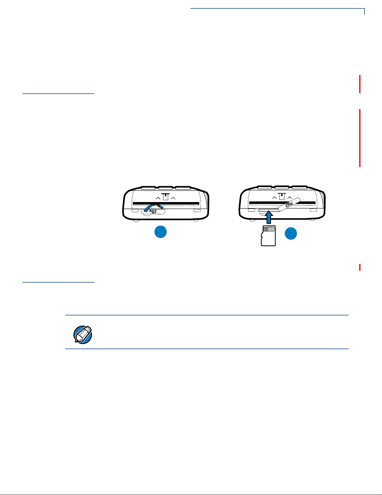
VX 675 3G supports micro SD card installation. Use the following procedures to
replace or install an SD card.
1 Turn off the terminal.
2 Lift and turn the rubber flap cover.
3 Insert the micro SD card. The card should lock in place when inserted
correctly.
4 Replace the rubber flap cover.
Using the
Battery
Battery Features
VX 675 terminal uses a single cell Li-ion battery (see Accessories and
Documentation for ordering information). The internal logic of the battery prevents
both overcharging and undercharging (a fault condition in which the battery level
goes well below the minimum acceptable charge and the battery becomes
unusable).
The VX 675 terminal will only operate when the battery is installed.
The following are features of the battery:
• One Li-ion cell.
• A safety circuit that:
• Prevents cell damage from overcharge, over-discharge, or overheating.
• Activates when the battery is left in an unused terminal for extended
periods.
VX 675 R
EFERENCE GUIDE 23
Page 24

TERMINAL SETUP
NOTE
NOTE
NOTE
NOTE
Battery Behavior (No Power Pack)
• VX 675 battery pack is not customer changeable and therefore should not be
disconnected and removed.
• Li-ion batteries are not affected by shallow charging. Furthermore, when the
terminal has no external power source or battery, the coin cell battery
provides power to the security circuit.
• Disconnecting and removing the battery, as well as unplugging the terminal
power pack, reduce the life of the coin cell battery, which does not recharge
and must be replaced if drained.
• Conserve battery power by turning the VX 675 terminal off when not in use.
Keep the Li-ion battery inserted in the terminal and power up the terminal
periodically to check the battery charge. Do not let the battery charge fall
below 10% for extended periods of time as this may permanently diminish the
battery capacity. Recharge the battery by attaching the micro-USB end of the
power pack to the terminal and plugging the other end of the power pa ck into
a wall outlet.
Battery Behavior
(No Power Pack)
Manual Startup
Manual Shutdown
The terminal shifts to power pack mode and starts up automatically when the
VX 675 is connected to a non-battery power source, regardless of the battery
charge state.
Hold the green key down for about 4 seconds until the terminal displays the
startup screen.
The 4-second power-up delay prevents terminal startup if the green key is
accidentally held down. The time required to hold the green key down to power up
the terminal is configurable.
The terminal lights up once the power is on.
The VeriFone copyright screen starts and displays a unique copyright screen
once the terminal loads an application. However,
screen after the initial VeriFone copyright screen if there is no available
application in the terminal.
Hold the red key down for about 4 seconds until the terminal displays the
shutdown verification screen. Keep holding the red key until the VX 675 terminal
shuts down.
DOWNLOAD NEEDED appears on
24 VX 675 REFERENCE GUIDE
• The 4-second shutdown delay that prevents terminal shutdown if the red key
is accidentally held down. The time required to hold the red key down to shut
down the terminal is configurable.
• The screen is blank when the terminal has no power.
Page 25
TERMINAL SETUP
CAUTION
WARNING
NOTE
Connecting the Terminal Power Pack
Connecting the
Terminal Power
Pack
After installing the battery, connect the VX 675 terminal to the provided power
source for initial charging.
Using an incorrectly rated power supply may damage the terminal or cause it not
to work as specified. Before troubleshooting, ensure that the power supply being
used to power the terminal matches the requirements specified on the bottom of
the terminal. (See Specifications for detailed power supply specifications.) Obtain
the appropriately rated power supply before continuing with troubleshooting.
Do not plug the power pack into an outdoor outlet or operate the terminal
outdoors.
During a transaction, disconnecting the power by removing the battery or
unplugging the terminal from a wall power while at very low battery charge may
cause transaction data files not yet stored in the terminal memory to be lost.
The VX 675 unit comes with a universal input power pack capable of operating
from voltages of 100 V to 240 V AC.
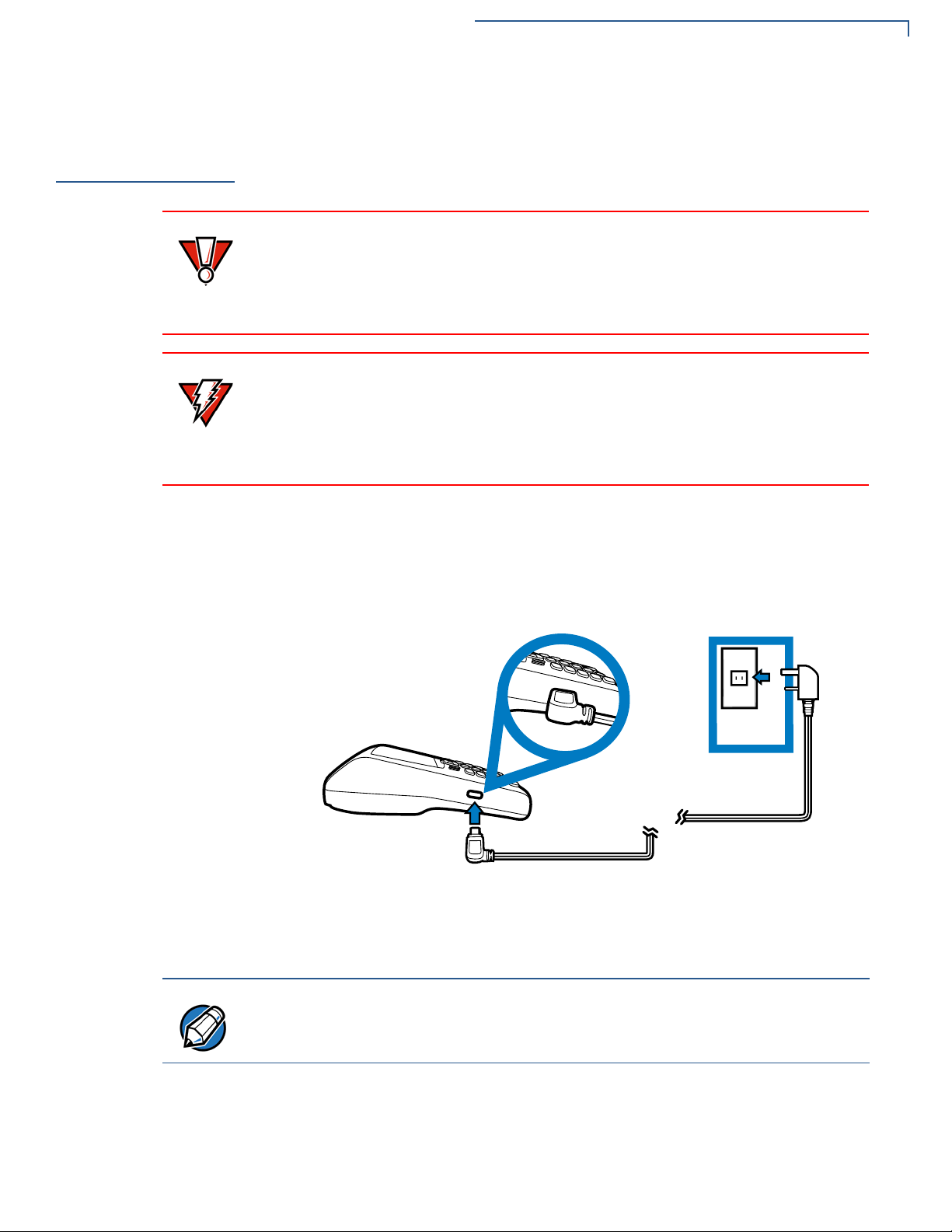
To Connect the
Terminal Power
Supply
1 Insert the micro-USB plug into the micro-USB port of the VX 675, as shown in
the figure below.
Figure 11 VX 675 Power Supply Connection
2 Plug the AC power pack into a wall outlet or powered surge protector.
To protect against possible damage caused by lightning strikes and electrical
surges, consider installing a power surge protector.
Once it loads the application, the terminal starts the initial VeriFone copyright
screen and displays a unique copyright screen. If there is no available application
in the terminal,
DOWNLOAD NEEDED appears on screen after the initial VeriFone
copyright screen.
VX 675 R
EFERENCE GUIDE 25
Page 26
TERMINAL SETUP
NOTE
NOTE
WARNING
Charging the Battery
Charging the
Battery
Battery Life
After unpacking your VX 675 terminal, connect the power pack to the unit for 4.65
hours or until fully charged.
The terminal charges the VX 675 battery when the terminal is in the base. For
more information, see Docking the Terminal on the Base.
The battery has a safety circuit to protect the Li-ion cells from overcharging and
over-discharging. If the battery is over-discharged, the safety circuit shuts down
the battery. The battery must then be recharged to restore operation.
The VX 675 terminal automatically shuts off when the battery reaches the
critically low charge state. If this occurs, the battery must be recharged for a
minimum of 1/2 hour before it can power the terminal. It may take several
recharge attempts to reset the safety circuit when charging a battery that has
been discharged below this critical state.
Charging and discharging the VX 675 battery hundreds of times will wear out the
battery. Significantly reduced operating times indicate the need for battery
replacement (see Accessories and Documentation for ordering information).
Using the VX 675
Base Stations
USB Base
Do not dispose of batteries in a fire. Li-ion batteries must be recycled
or disposed of properly . Do not dispose of Li-ion batteries in municip al
waste sites.
Like the terminal, VeriFone ships variants of the VX 675 base for different
markets. Your base may have a different configuration.
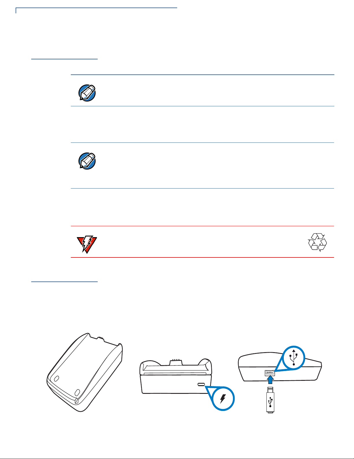
A charging base to charge the terminal and provide a docking station when the
terminal is not in use. It also has USB Host port for downloading applications and
secure keys via USB flash drive. The base can be positioned on a countertop.
26 VX 675 REFERENCE GUIDE
Figure 12 USB Base Showing Micro-USB and USB Host Ports
Page 27
TERMINAL SETUP
Powering Up the Base
Full-Feature Base
Powering Up the
Base
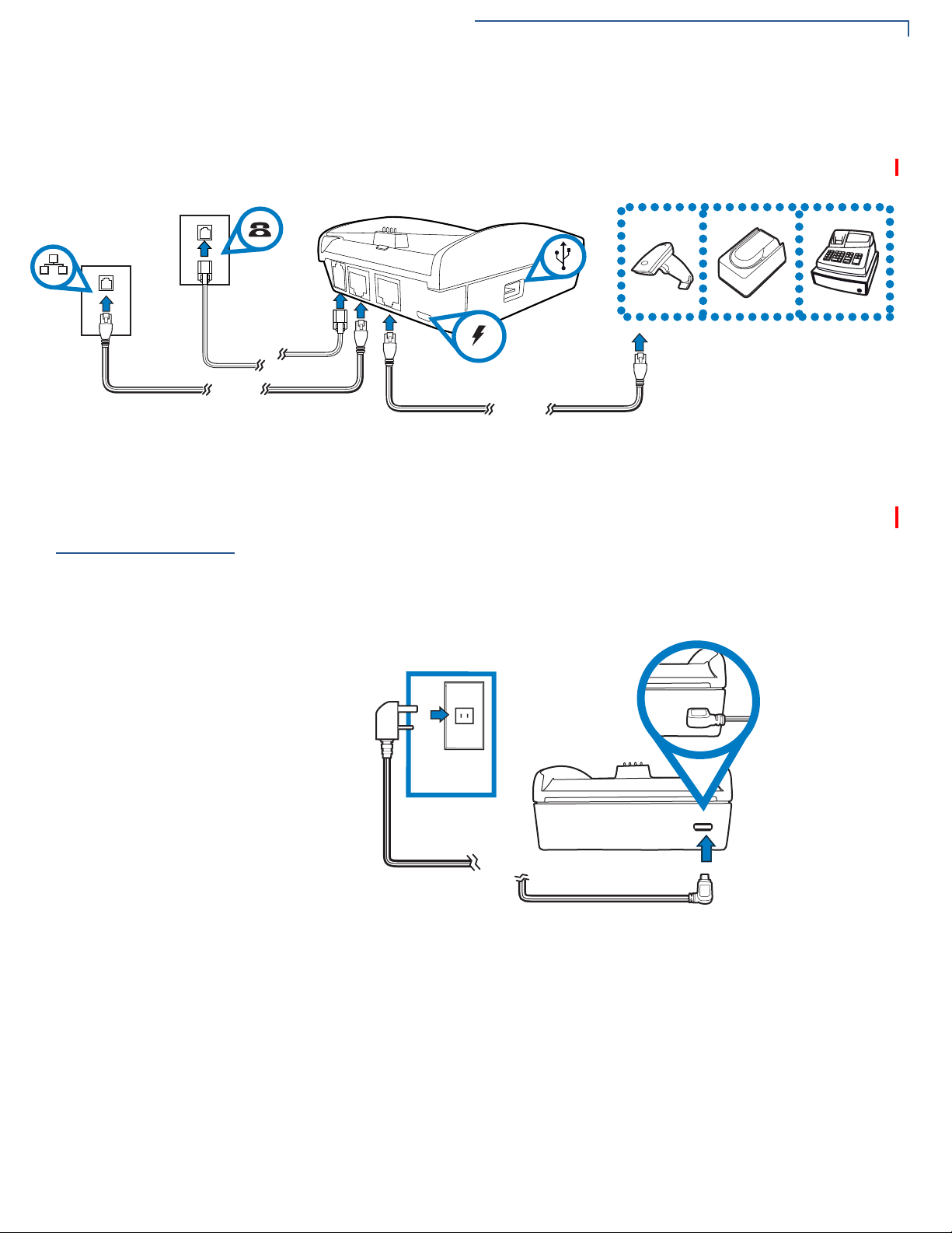
A charging base with Dial, Ethernet, Serial (RS-232), and USB Host ports for full
back-up connectivity options and support to some peripherals like ECR, check
reader, and barcode reader, among others.
Figure 13 Full-Feature Base Showing Dial, Ethernet, Serial, Micro-USB
and USB Host Ports
Use the procedure in this section to connect the VX 675 Base to a power source.
To power up the base
1 Insert the micro-USB plug into the micro-USB port of the base, as shown in
the figure below.
Figure 14 Connecting the Base to a Power Source
2 Plug the AC power pack into a wall outlet or power surge protector.
VX 675 R
EFERENCE GUIDE 27
Page 28
TERMINAL SETUP
$
$ %
NOTE
WARNING
Docking the Terminal on the Base
Docking the
Terminal on the
Base
Undocking the
Te rminal fro m
the Base
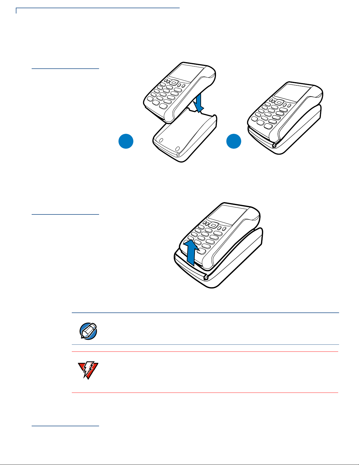
The VX 675 terminal can be placed on the base when not in use for continuous
charging of its battery.
Figure 15 Docking the VX 675 Terminal on the Base
The VX 675 terminal can be taken from the base when in use.
Conducting
Wireles s
Transactions
28 VX 675 REFERENCE GUIDE
Figure 16 Undocking the VX 675 Terminal from the Base
To protect against possible damage caused by lightning strikes and electrical
surges, consider installing a power surge protector.
Do not plug the power pack into an outdoor outlet or operate the terminal
outdoors.
Disconnecting the power during a transaction may cause transaction data files
not yet stored in terminal memory to be lost.
To conduct a wireless transaction:
• Ensure the terminal is in an optimal position for transmitting.
• Follow the on-screen instructions provided with your application.
Page 29
TERMINAL SETUP
CAUTION
Conducting Smart Card Transactions
Conducting
Smart Card
Transactions
To Conduct a Smart
Card Transaction
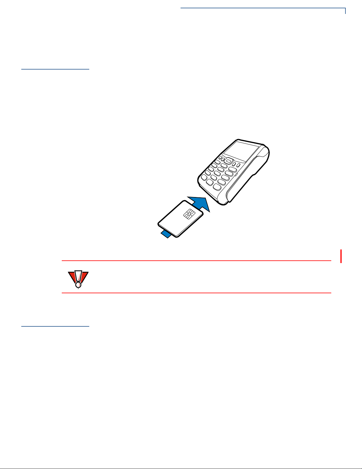
The smart card transaction procedure may vary from one application to another.
Verify the procedure with your application provider before performing a smart card
transaction.
1 Position a smart card with the contacts facing upward (see illustration below).
2 Insert the smart card into the smart card reader slot in a smooth, continuous
motion until it seats firmly.
3 Remove the card only when the application indicates the transaction is
complete.
Using the
Magnetic Card
Reader
To Conduct a Credit
or Debit Card
Transaction
Figure 17 Inserting a Smart Card
Do not remove the smart card in the card reader until the transaction is complete.
Premature card removal will invalidate the transaction.
The VX 675 terminal supports credit/debit card transactions.
1 Position a magnetic card with the stripe in the card reader and facing inward,
toward the keypad.
2 To ensure a prope r read of the magnetic swipe card, the user should insert the
magnetic card from the top of the unit, as shown in the following illustration.
VX 675 R
EFERENCE GUIDE 29
Page 30
TERMINAL SETUP
Connecting to USB Host
3 Swipe the card through the magnetic card reader.
Figure 18 Using the Magnetic Card Reader
Connecting to
USB Host
To connect to the
USB Host
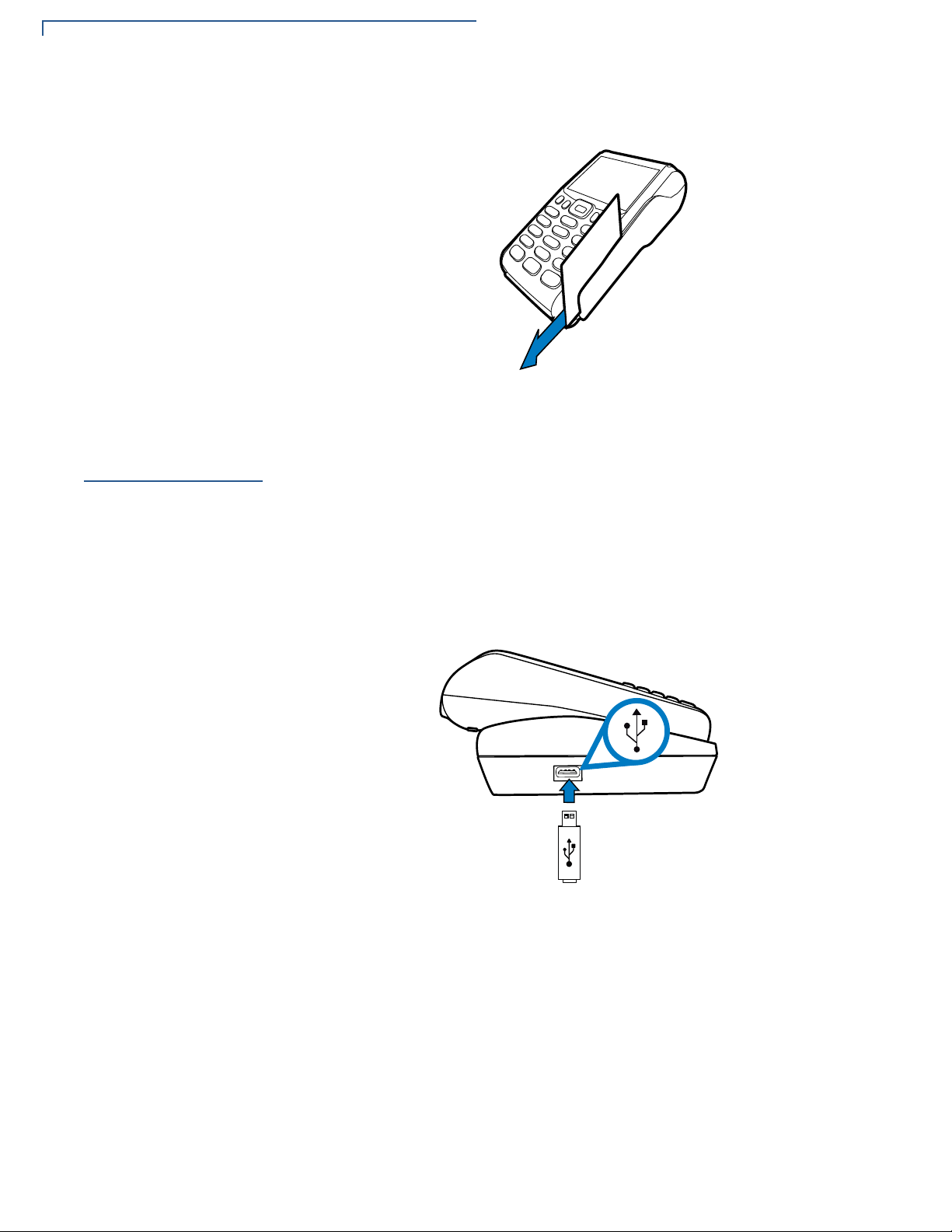
USB Host support, allows you to download applications and secure keys via USB
flash drive.
1 Power up the base by inserting the micro-USB plug into the micro-USB port of
the base as shown in Figure 14.
2 Make sure that the terminal is docked on the base.
3 Insert the USB plug into the USB Host port on the left side of the base.
30 VX 675 REFERENCE GUIDE
Figure 19 Connecting USB Flash Drive to the USB Host
Page 31

TERMINAL SETUP
VX 675 ECR (Fiscal Module) Support
VX 675 ECR
(Fiscal Module)
Support
Customer Display
The fiscal module allows ECRs to have direct connection to the Ministry of
Finance servers. When a mobile transaction is made, the transaction data is sent
over to the Ministry of Finance servers, and then goes to the banking host system.
The fiscal module stores the transaction data (up to 2 MB). A metallic seal is
placed on the right side, under the MSR to secure the fiscal module.
A 42mm single line customer-facing display (no backlight) that can display up to 8
characters including “,” or “.” between any character. It is located below the paper
roll cover.
VX 675 3G and
GPS Support
GPS Receiver
Connecting by 3G
Figure 20 VX 675 ECR Customer Display
VX 675 3G uses the Cinterion PHS8-P radio module that incorporates 3G HighSpeed Packet Access (HSPA+) connectivity. The PHS8-P radio module is
optimized for high bandwidth and allows a downlink speed of 14.4 Mbps and an
uplink speed of 5.7 Mbps.
The Cinterion PHS8-P radio module integrates a GPS receiver that offers the full
performance of GPS/A-GPS technology.
To connect to existing 3G operator-provided infrastructure, check that SIM has
been inserted, see Installing the SIM Card.
VX 675 R
EFERENCE GUIDE 31
Page 32

TERMINAL SETUP
VX 675 3G and GPS Support
32 VX 675 REFERENCE GUIDE
Page 33

Using the Terminal Keys
NOTE
Before proceeding to other tasks, familiarize yourself with the operational features
of the VX 675 terminal keypad to enter data.
This section describes how to use the VX 675 keypad, which consists of four
programmable function keys (PF1 to PF4), a 5-way navigation key, a 12-key
telephone-style main keypad (0 to 9, *, and #), and three command keys
(CANCEL, CLEAR, and ENTER).
Using these keys, you can perform all data-entry tasks described in this manual.
The function keys allow you to navigate though the system mode menus and
select specific operations.
For added convenience, the keypad is automatically back-lit when you power on
the terminal.
CHAPTER 3
Figure 21 Front Panel Key Arrangement.
Actual keypad may vary.
VX 675 REFERENCE GUIDE 33
Page 34

USING THE TERMINAL KEYS
NOTE
NOTE
Data Entry Modes
Data Entry
Modes
Before you can use the keys on the front panel to enter ASCII characters, the
VX 675 terminal must be in a mode that accepts keyed data entry. There are two
terminal operating modes, each enabling you to press keys to enter data under
specific circumstances:
• Normal mode: This is the terminal operating mode where an application
program is present in mDRAM and currently running.
• Verix Terminal Manager (VTM) mode: This is a special, pa ssword-controlled
terminal operating mode for performing a variety configuration procedures that
cannot be performed when an application is running.
If you enter Verix Terminal Manager while a terminal application is running in
normal mode, Verix Terminal Manager preempts the application and takes
control of the display and keyboard. The only way to exit V erix Terminal Manager
is to restart the terminal. For this reason, once you enter the Verix Terminal
Manager, you cannot return to the application in the same session.
If you turn on a VX 675 terminal with an application stored in memory and *GO
variable set to the application name, the application executes and the terminal
automatically enters normal mode. The application then controls how terminal
keys process transactions and when you can use specific keys to type characters
or respond to prompts.
Main Keypad
The main keypad is a 12-key telephone-style main keypad.
The VTM functions described in the V erix Terminal Manager section requires you
to enter numbers, letters, or symbols using the keypad.
Using the keypad, you can enter up to 50 ASCII characters, including the letters
A–Z, the numerals 0–9, and the following 20 special characters: (*), (,), (‘), (“), (-),
(.), (#), (%), (:), (!), (+), (@), (=), (&), (space), (;), ($), (_), (\), and (/).
Alphabetic characters are entered by pressing its corresponding number in the
keypad multiple times within a given time.
Characters found in the * and # keys may vary in some units (for example, VX 675
with ECR fiscal module functionality).
34 VX 675 REFERENCE GUIDE
Page 35

USING THE TERMINAL KEYS
NOTE
Main Keypad
Command Key
Descriptions
The following are the command keys of the terminal’s keypad.
The terminal’s operating mode and context determine the specific action
performed when you press one of the function keys. The following descriptions
are provided solely to acquaint you with some general characteristics of these
function keys before presenting more detailed Verix Terminal Manager
procedure descriptions.
Cancel Key
Pressing the Cancel key in normal mode — when the terminal’s application is
loaded and running. It terminates the current function or operation.
In Verix Terminal Manager, use Cancel to perform a variety of functions. The
most common use of Cancel in V erix Terminal Manager is to exit a Verix T erminal
Manager submenu and return to the main Verix Terminal Manager menu. The
specific effect of pressing the Cancel key depends on the currently active Verix
Terminal Manager menu.
On VX 675 ECR units, the red key may display a string of letters.
Clear Key
In normal mode, the Clear key is commonly used to delete a number, letter, or
symbol on the terminal’s display screen. Press Clear one time to delete the last
character typed on a line. To delete additional characters, moving from right-toleft, press Clear once for each character or hold down Clear to delete all
characters in a line.
In Verix Terminal Manager, the specific effect of pressing the Clear key depends
on the currently active Verix Terminal Manager menu.
Enter Key
In normal mode, the Enter key is generally used in the same way as the enter
key on a PC, that is, to end a procedure, confirm a value or entry , answer “Yes” to
a query, or select a displayed option.
In Verix Terminal Manager, press the Enter key to begin a selected procedure,
step forward or backward in a procedure, and confirm data entries. The specific
effect of the Enter key depends on the currently active Verix Terminal Manager
menu.
On VX 675 ECR units, the green key may display a new currency symbol.
VX 675 R
EFERENCE GUIDE 35
Page 36

USING THE TERMINAL KEYS
Main Keypad
36 VX 675 REFERENCE GUIDE
Page 37

Verix Terminal Manager
This chapter describes a category of terminal functions called terminal manager
operations.
• Press ENTER and 7 keys at the same time and enter the password to open the
Verix Terminal Manager (VTM). See Entering Verix Terminal Manager.
• Since files are loaded into specific groups, VTM users can view files, delete
files, and manage configuration variables. See File Groups.
• Use the system and file group passwords to secure applications and
information on the terminal. See Passwords.
• Use the terminal manager menus and submenus to configure terminals;
download and debug applications; perform diagnostics such changing console
settings, managing keys and view terminal information; and perform routine
tests and terminal maintenance. See Verix Terminal Manager Menus.
CHAPTER 4
When to Use
Ve rix Terminal
Manager
Verix Terminal Manager is used exclusively by those responsible for configuring,
deploying, and managing on-site VX 675 terminal installations.
Use the Verix Terminal Manager functions to perform different subsets of related
tasks:
• Application programmers configure a development terminal, download
development versions of the VX 675 application program, then test and debug
the application until it is validated and ready to be downloaded to other
terminals.
• Deployers of VX 675 terminals to end-user sites perform the specific tasks
required to deploy a new VX 675 terminal on-site, including configuring the
terminal, downloading application software, and testing the terminal prior to
deployment.
• Terminal administrators or site managers change passwords, perform
routine tests and terminal maintenance, and configure terminals for remote
diagnostics.
To perform the subset of tasks that corresponds to a job, select the appropriate
Verix Terminal Manager menu(s) and execute the corresponding procedure(s).
VX 675 REFERENCE GUIDE 37
Page 38

VERIX TERM INAL MANAGER
NOTE
Local and Remote Operations
Local and
Remote
Operations
Verifying
Terminal Status
The terminal manager operations available on a VX 675 terminal can be divided
into the following two categories or types:
• Local operations address a stand-alone terminal and do not require
communication or data transfers between the terminal and another terminal or
computer. Perfor m local Verix Terminal Manager operations to configure, test,
and display information about the terminal.
• Remote operations require communication between the terminal and a host
computer (or another terminal) over a cable connection. Perform remote Verix
Terminal Manager operations to download application software to the
terminal, upload software from one terminal to another, or download using a
service dongle from VeriCentre or from another download host.
This chapter contains descriptions on how to perform local Verix Terminal
Manager operations. For information on performing remote operations, such as
downloads, refer to the Performing Downloads section.
The VX 675 terminal you are using may or may not have an application program
running on it. After you have set up the terminal (refer to Terminal Setup) and the
terminal is turned on, use the following guidelines to verify terminal status
regarding software and current operating mode:
Entering Verix
Terminal
Manager
• If no application program is loaded into terminal memory, the message
DOWNLOAD NEEDED appears on the display screen.
From this point, press ENTER and 7 key simultaneously to access Verix Terminal
Manager and perform the required download.
• If an application program is loaded and *GO is set in the configuration file in
group 1 to the application’s name into terminal memory, an applicationspecific prompt appears. The application is running and the terminal is in
normal mode. If all installation steps are complete, the terminal can process
transactions.
To prevent unauthorized use of the Verix Terminal Manager menus, the VX 675
terminal OS requires a system password each time you enter Verix Terminal
Manager. To access the Verix Terminal Manager password entry screen,
simultaneously press the
passw ord is “166831.” Use the following key sequence to enter this password:
1 6 6 8 3 1 ENTER
ENTER and 7 keys.The default, factory-set system
38 VX 675 REFERENCE GUIDE
After entering the correct password, the terminal enters the terminal manage r and
displays the first terminal manager main menu. You can now cycle through all
Verix Terminal Manager main menus.
Page 39

VERIX TERMINAL MANAGER
CAUTION
NOTE
File Groups
File Groups
The VX 675 operating system implements a file system in memory. Files are
assigned to one of 15 groups for access control. Groups are similar to directories
on a computer in that different applications can be stored in separate file groups,
just like different computer applications can be stored in separate directories.
Groups are referred to as Group n or GIDn throughout this manual.
Each group is protected by a separate password, and each has a separate
CONFIG.SYS file. The following rules apply to the VX 675 file group system:
• The primary application must be downloaded into Group 1.
• On terminal power up and after a restart, the terminal defaults to Group 1 as
the controlling group.
• Group 1 applications have access to files stored in all groups. Other
applications can reside in Groups 2 – 14.
• Applications in a group other than Group 1 have access only to themselves
and files stored in Group 15.
• Group 15 is globally accessible, making it an ideal location for files shared by
multiple applications, such as shared libraries.
• File Groups 1 – 15 are empty until they are filled through a download to the
VX 675 terminal.
Passwords
For more information on managing file groups, refer to the Verix eVo Volume I:
Operating System Programmers Manual -VPN DOC00301.
Handle passwords as you would PC passwords.
If you change a password but forgot it later on, there is no password recovery
method. Without the password, you are unable to access Verix Terminal
Manager operations and may be prevented from requesting a download,
performing remote diagnostics, or changing any of the information already stored
in memory. The terminal can, however, continue to process transactions in
normal mode.
If you forget or lose the system password to your terminal, please contact your
local VeriFone representative for assistance.
Passwords must be in numeric characters only and must be greater than five
digits and less than 10 digits in length.
VX 675 R
EFERENCE GUIDE 39
Page 40

VERIX TERM INAL MANAGER
NOTE
Verix Terminal Manager Menus
System Password
File Group
Passwords
Verix Terminal
Manager Menus
When you key in the system password to enter terminal manager, an asterisk (*)
appears for each character you type. These asterisks prevent your password from
being seen by an unauthorized person.
Some application program downloads automatically reset the system password.
If your system password no longer works, check if a download has changed your
password.
From manufacture, each file group uses the default password “166831,” which is
entered as follows:
1 6 6 8 3 1, and press
ENTER
The two main terminal manager menus are listed in the following table.
VERIX TERMINAL MGR
1> Restart
2> Edit Parameters
3> Download
4> Memory Usage
5> Directory Listing
6> Clear Memory
7> Calibrate Screen
8> Te rminal In fo
9> Diags
Figure 22 Menu 1
VERIX TERMINAL MGR
1> System Error Log
2> Clock
3> Console Settings
4> Change Passwords
5> Key Management
Figure 23 Menu 2
On successful entry of the system password,
VERIX TERMINAL MGR menu appears.
40 VX 675 REFERENCE GUIDE
Page 41

VERIX TERMINAL MANAGER
Verix Terminal Manager Menus
to return to a previous menu, press the UP icon () on the left side of the screen.
V erix Terminal
Manager
Procedures
To go to the next menu, press the
side of the screen,
the list. Pressing
UP () and DOWN (), are used to select any submenu from
ENTER will choose the highlighted function. To return to the main
Verix Terminal Manager menu and cancel any changes, press the
DOWN icon (). The smaller arrows on the right
CANCEL key.
The user can also select the item from the menu by pressing the corresponding
number key indicated at the left of the item selected.
Each menu has items to select; some items contain submenus or a series of
prompts. When prompted to enter alphabetic or special characters, use the
procedure described in Chapter 3.
When performing downloads or operations that change or clear files, the
password for each file group is required. The password is only required once per
session per file group.
The procedures in this section explain how to use each of the Verix Terminal
Manager menus. Each procedure description starts at a main Verix Terminal
Manager menu. Each procedure takes you step-by-step t hrough a complete Verix
Terminal Manager operation in the following sequence:
1 When the main Verix Terminal Manager menu appears, scroll up or down
using the
an operation.
UP () and DOWN () icons on the right side of the screen to select
2 Press ENTER to select the operation.
3 Complete the operation.
4 Return to the main Verix Terminal Manager menu.
Procedure descriptions are arranged in the following tabular format:
Table 3 Procedural Description Example
Display Action
Screen displayed
Submenu Row
Screens displayed on
submenu selection
Action required
Action required
VX 675 R
EFERENCE GUIDE 41
Page 42

VERIX TERM INAL MANAGER
NOTE
Verix Terminal Manager Menus
The Display column in Table 3 indicates what appears on the terminal display
screen at each step of the procedure. Please note the following conventions used
in this column:
• If a prompt or message appears on the screen exactly as it is described, it is
shown in Arial bold font and in lower case with the first letter capitalized. For
example,
Download Needed.
• If text is enclosed in parentheses, the actual text or message may vary
depending on the terminal version you have. For example, in (Application
Prompt), the normal font is used and text appears in lower case with first letter
capitalized.
The Action column provides a procedural description that:
• Describes the current step and context of the procedure.
• Indicates the entries to perform using the keypad in response to a prompt or
message.
Enter and Exit Verix
Terminal Manager
• Provides additional explanations or information about the steps of that
particular Verix Terminal Manager menu.
A submenu row indicates a specific menu evoked from a main menu screen. A
description of that screen and procedure immediately follows the submenu row.
The following keys have the same function on all submenus:
• Press the ENTER key to choose the function and display the submenu
selected. When editing, pressing
ENTER will save a newly entered variable.
• Press the CANCEL key to exit any submenu without saving changes.
To enter terminal manager after you have turned on the VX 675 terminal, follow
the procedure described below.
On successful completion, some operations automatically exit Verix Terminal
Manager and restart the terminal. Other operations require that you exit Verix
Terminal Manager and restart the terminal. To manually exit Verix Terminal
Manager, select
1> RESTART in VERIX TERMINAL MGR.
42 VX 675 REFERENCE GUIDE
Page 43

Table 4 Enter Verix Terminal Manager
Display Action
VERIX TERMINAL MANAGER
Verix Terminal Manager Menus
VERIFONE VX675
QT65010M
03/09/2012 Verix
COPYRIGHT 1997-2012
VERIFONE
ALL RIGHTS RESERVED
BATTERY 100%
FOR STATUS PRESS KEY 3
VERIFONE VX675
QT65010M
03/09/2012 Verix
* * T A M P E R * *
At startup, the terminal displays a copyright notice
screen that shows the terminal model number , the
OS version of the VX 675 stored in the terminal’s
memory, the date the firmware was loaded into
the terminal, and the copyright notice.
This screen appears for three seconds, during
which time you can enter Verix Terminal Manager
by simultaneously pressing
ENTER and 7 key.
You can extend the display period of this screen
by pressing any key during the initial three
seconds. Each keypress extends the display
period an additional three seconds.
If the battery has not been initially charged, the
screen displays
BATTERY NOT CALIBRATED to
inform the user to initialize and condition the
battery.
For more information about the battery, refer to
VX 675 Battery Informat ion .
If an attempt to break into the terminal’s system
has been made, the message
**TAMPER** is
displayed in place of the certificate. The terminal
will remain in this state until the condition has
been remedied.
COPYRIGHT 1997-2012
VERIFONE
ALL RIGHTS RESERVED
<application prompt>
If an application already resides on the terminal,
an application-specific prompt is displayed.
Otherwise, an error message is displayed. For
more information on startup errors, see STARTUP
ERRORS.
VX 675 R
EFERENCE GUIDE 43
Page 44

VERIX TERM INAL MANAGER
Verix Terminal Manager Menus
Table 4 Enter Verix Terminal Manager (continued)
Display Action
TERMINAL MGR ENTRY
Please Enter Password
___________________
VERIX TERMINAL MGR
1> Restart
2> Edit Parameters
3> Download
4> Memory Usage
5> Directory Listing
6> Clear Memory
7> Calibrate Screen
8> Te rminal In fo
9> Diags
If an application prompt appeared and you chose
to enter the terminal manager, you are prompted
to type the system password.
Use the default password “166831.” This
password is entered as: 1 6 6 8 3 1, an d press
ENTER.
Use CLEAR to delete the entry and correct any
mistakes. If you enter an incorrect password, the
terminal exits the
TERMINAL MGR ENTRY screen.
Verify your password and reenter it.
To quit this operation and return to the application
prompt or
CANCEL.
DOWNLOAD NEEDED screen, press
The first of the two VERIX TERMINAL MGR menus
is displayed. T o go to
2, tap the
DOWN icon () on the left of the
screen. To toggle with the submenus,
) and DOWN () until you reach the desired menu
(
then press ENTER.
VERIX TERMINAL MGR menu
use the UP
You can also choose an option in the menu by
pressing the corresponding number on the
keypad.
44 VX 675 REFERENCE GUIDE
Page 45

VERIX TERMINAL MANAGER
Verix Terminal Manager Menus
Menu 1
In this menu you can restart the terminal, edit parameters, download terminal
software updates, check memory usage and availability, as well as view the
contents of I: drive and F: drive directories. You can also clear the memory and
calibrate the touchscreen.
Table 5 Verix Terminal Manager Menu 1
Display Action
VERIX TERMINAL MGR
1> Restart
2> Edit Parameters
3> Download
4> Memory Usage
5> Directory Listing
6> Clear Memory
7> Calibrate Screen
8> Te rminal In fo
9> Diags
To restart the terminal, select 1> RESTART.
To edit the parameters, select 2>
EDIT PARAMETERS. (For more information, refer
to the Edit Keyed Files section that follows this
main menu description.)
To download applications, select
To view memory usage, select
USAGE
To view directory listing, select
LISTING
To clear the memory, select
3> DOWNLOAD.
4> MEMORY
.
5> DIRECTORY
.
6> CLEAR MEMORY.
2> EDIT PARAMETERS
VTM SELECT GROUP
GROUP ID: nn
APP: <*APNAME or application or EMPTY or
NOT EMPTY>
To test and calibrate the screen, select
CALIBRATE SCREEN.
To view terminal information, select
INFO.
To view diagnostics, select
9>DIAGS.
7>
8> TERMINAL
To toggle to VERIX TERMINAL MANAGER menu 2,
press
DOWN icon () or to quit any operation
within this menu, press
CANCEL.
The file group number is represented as Gnn or
GROUP nn
. Type the Group ID of the file group (1
for the primary application; between 1–15 for o ther
applications) into which to perform the download.
(Refer to Chapter 6 for detailed download
instructions and information).
To select the
icon
(). The application name will appear if
Group ID, use the UP () and DOWN
*APNAME is set in the group and also if there are
files in the group selected.
After you select a file group number, press
VX 675 R
EFERENCE GUIDE 45
ENTER.
Page 46

VERIX TERM INAL MANAGER
Verix Terminal Manager Menus
Table 5 Verix Terminal Manager Menu 1 (continued)
Display Action
VERIX TERMINAL MGR
Please enter
Password for GID n:
___________________
3> DOWNLOAD
VERIX TERMINAL MGR
Group ID: _1
To continue, enter the required password. If you
enter an incorrect password, the following
message appears:
Change Passwords Gn
Please Try Again
Press ENTER. Verify your password and reenter it.
To continue, enter the Group ID. The value of 1 is
for the primary application while value between 115 is for other applications. Then, press
To return immediately to
MGR MENU or to quit any operation within this
menu, press
CANCEL.
VERIX TERMINAL
ENTER.
VTM DOWNLOAD MGR Gn
1> Single-app
2> Multi-app
46 VX 675 REFERENCE GUIDE
For a single application download, select Single-
. For multiple application download, select
app
Multi-app.
Note: Multi-app is only available for group 1.
(Refer to Chapter 6 for detailed download
instructions and information).
To select
, use the UP () and DOWN icon ()
then press ENTER. Y ou can also choose an option
in the menu by pressing the corresponding
number on the keypad.
To return to
CANCEL.
VERIX TERMINAL MGR, press
Page 47

Table 5 Verix Terminal Manager Menu 1 (continued)
Display Action
VERIX TERMINAL MANAGER
Verix Terminal Manager Menus
VTM DOWNLOAD MGR Gn
1> Full dnld
2> Partial dnld
VTM DOWNLOAD MGR Gn
**** WARNING ****
All Files Will Be
Cleared From Group n
1> Cancel Download
2> Continue
Select the type of download mode: Full dnld or
Partial dnld
. A full download will delete all data on
the group’s memory. A partial download only adds
new files to the group’s memory. If a downloaded
file is identical to an existing file in the memory,
the existing file is replaced.
To select
, use the UP () and DOWN icon ()
then press ENTER. You can also choose an option
in the menu by pressing the corresponding
number on the keypad.
To return to
CANCEL.
VERIX TERMINAL MGR, press
If you selected FULL on a single application
download, a screen will appear warning you that
all existing files in the selected group will be
deleted.
To return to
CANCEL or press ENTER to continue downloading
VERIX TERMINAL MGR, press
an application.
VTM DOWNLOAD MGR Gn
Clear Application
From Group nn?
1> Yes
2> NO
If you selected FULL on a multiple application
download, you will be prompted to clear the
existing application on the currently selected
group. Select
YES to continue or NO to cancel
downloading applications.
VX 675 R
EFERENCE GUIDE 47
Page 48

VERIX TERM INAL MANAGER
Verix Terminal Manager Menus
Table 5 Verix Terminal Manager Menu 1 (continued)
Display Action
VTM DOWNLOAD MGR Gn
**** WARNING ****
Confirm Deletion
For Application
1> Yes
2> NO
VTM DOWNLOAD MGR Gn
GIDS TO ERASE:
1,2,4
1> Change choices
2> Continue
If you selected YES from the previous screen, a
confirmation screen appears. Select
confirm or
NO to cancel the deletion.
YES to
If a FULL multiple download has been previously
done, this screen appears instead of the previous
two screens. This screen lists all the erased GIDs
on the previous download. Select
CONTINUE to
erase all memory.
VTM DOWNLOAD MGR Gn
1> Modem
2> COM1
3> COM7
4> SD Card
5> USB Flash Memory
6> TCPIP
7> USB Dev
8> COM6
9> COM2
If a Partial download has been selected, select the
download mode in this screen.
An application that supports the TCP stack is
loaded with the OS to be able to use the
6> TCPIP
option. If no application can be found, an error
message appears.
Note: Not all listed options are available for all
platforms.
To return to the main menu without saving your
selection, press
CANCEL.
48 VX 675 REFERENCE GUIDE
Page 49

Table 5 Verix Terminal Manager Menu 1 (continued)
Display Action
VERIX TERMINAL MANAGER
Verix Terminal Manager Menus
VTM DOWNLOAD MGR Gnn
*ZP Host Phone num
___________________
___________________
VTM DOWNLOAD MGR Gnn
Unit Receive Mode
WAITING FOR DOWNLOAD
If you selected 1> MODEM and *ZP (host phone
number) is not defined, you must enter valid
phone number (up to 32 characters long) and
press
ENTER.
Select 2> COM1 to download via the COM 1 port.
Select
3> COM7 to download via the COM 7 port.
To return to the main menu without saving your
selection, press
CANCEL.
VTM DOWNLOAD MGR Gnn
Unavailable
VTM DOWNLOAD MGR Gnn
Unavailable
Select 4> SD CARD to download from a stored
digital (SD) card.
If no SD Card is inserted in the unit, the
‘Unavailable’ message is shown.
To return to the main menu without saving your
selection, press
CANCEL.
Select 5> USB FLASH MEMORY to download from
a memory stick.
If no Memory Stick is inserted in the unit, the
‘Unavailable’ message is shown.
To return to the main menu without saving your
selection, press
CANCEL.
VX 675 R
EFERENCE GUIDE 49
Page 50

VERIX TERM INAL MANAGER
Verix Terminal Manager Menus
Table 5 Verix Terminal Manager Menu 1 (continued)
Display Action
VTM DOWNLOAD MGR Gnn
No *ZTCP Variable
and no VxEOS
VTM DOWNLOAD MGR Gnn
Unit Receive Mode
WAITING FOR DOWNLOAD
Select 6> TCPIP to download from your TCPIP
connection.
An application that supports the TCP stack is
loaded with the OS to be able to use the
6> TCPIP
option. If no application can be found, an error
message appears.
Not all listed options are available for all platforms.
Select 7> USB DEV to download using the USB
connection.
To return to the main menu without saving your
selection, press
CANCEL.
VTM DOWNLOAD MGR Gnn
Unavailable
VTM DOWNLOAD MGR Gnn
Unavailable
Select 8> COM6 to download via the COM 6 port.
To return to the main menu without saving your
selection, press
CANCEL.
Select 9> COM2 to download via the COM 2 port.
To return to the main menu without saving your
selection, press
CANCEL.
50 VX 675 REFERENCE GUIDE
Page 51

Table 5 Verix Terminal Manager Menu 1 (continued)
Display Action
VERIX TERMINAL MANAGER
Verix Terminal Manager Menus
VTM DOWNLOAD MGR Gnn
*ZP HOST
ADDR (IP:PORT)
___________________
___________________
VTM DOWNLOAD MGR Gnn
*ZP HOST ADDR
___________________
___________________
If you selected 6> TCPIP and *ZP (TCP address) is
not defined, you must enter a valid TCP address
(up to 40 characters long including the colon and
port number) and press
ENTER.
VTM DOWNLOAD MGR Gnn
*ZP HOST ADDR PORT
___________________
VX 675 R
EFERENCE GUIDE 51
Page 52

VERIX TERM INAL MANAGER
Verix Terminal Manager Menus
Table 5 Verix Terminal Manager Menu 1 (continued)
Display Action
VTM DOWNLOAD MGR Gnn
*ZT TERMINAL ID
___________________
VTM DOWNLOAD MGR Gnn
*ZA APPLICATION ID
___________________
If *ZT (terminal ID used by VeriCentre) is not
defined, you must enter a valid terminal ID (up to
15 characters long) and press
ENTER.
If *ZA (application ID) is not defined, you must
enter a valid application ID (up to 10 characters
long) and press
ENTER.
VTM DOWNLOAD MGR Gnn
*ZA= nnnn
*ZP= nnnn
*ZR= nnnn
*ZT= nnnn
1> Edit
2> Start
You can view the specified values on the
confirmation screen. Select
and modify the specifications or
1> EDIT to go back
2> START to begin
the download.
52 VX 675 REFERENCE GUIDE
Page 53

Table 5 Verix Terminal Manager Menu 1 (continued)
Display Action
VERIX TERMINAL MANAGER
Verix Terminal Manager Menus
VTM DOWNLOAD MGR Gnn
UNIT RECEIVE MODE
***________________
VTM DOWNLOAD MGR
GROUP n PA SSWORD
___________________
If you selected 2> COM1 or 3> COM7 , a line of
asterisks appears that shows the percentage of
completion. Each asterisk equals approximately
10% of the download.
You can cancel a download in progress by
pressing
Note:
CANCEL. Doing so restarts the terminal.
If you have not previously entered a
group’s password in this session, the
terminal prompts for the group’s
password prior to downloading
applications.
To continue, enter the required password. If you
enter an incorrect password,
PLEASE TRYAGAIN
appears.
ENTER. Verify your password and reenter it.
Press
4> MEMORY USAGE
MEMORY USAGE
Drive I: Files__________ 2
Inuse__________10 KB
Drive F: Files_________0
Inuse_________0
RAM Avail_______29168 KB
FLASH Avail _______124158 KB
This screen displays how much mDRAM is used
and how much is available.
• INUSE - Closest estimate of used memory (in
KB).
• AVAIL - Lowest number of free memory (in KB).
To return to the main menu, press
Note: RAM memory is the terminal working
CANCEL.
memory. RAM memory is where the OS
and applications execute. It is completely
separate from the FLASH memory.
FLASH memory is where code and data
is stored when it is not executing. RAM
and FLASH are physically different and
are different sizes.
VX 675 R
EFERENCE GUIDE 53
Page 54

VERIX TERM INAL MANAGER
Verix Terminal Manager Menus
Table 5 Verix Terminal Manager Menu 1 (continued)
Display Action
5> DIRECTORY LISTING
NAVIGATION CONTROLS
2/8 Up/Down
1/7 Page Up/Down
* Send to Com Port
# Send to Printer
ENT Select
CAN Return
PRESS ENTER TO CONT
SELECT DRIVE
I :
F:
N:
To continue, enter the Group ID. The value of 1 is
for the primary application while value between 115 is for other applications. Press
ENTER.
CONFIG.SYS protected records that begin with *
or # are retained when you clear a mDRAM file
group.
This screen shows the different Directory .
To return to the main menu, press
To return immediately to
MGRMENU1
menu, press
or to quit any operation within this
CANCEL.
VERIX TERMINAL
CANCEL.
54 VX 675 REFERENCE GUIDE
Page 55

Table 5 Verix Terminal Manager Menu 1 (continued)
Display Action
6> CLEAR MEMORY
VERIX TERMINAL MANAGER
Verix Terminal Manager Menus
VERIX TERMINAL MGR
Group ID: _1
VERIX TERMINAL MGR
1> Clear CONFIG. SYS
2> Clear Split Files
3> Clear GID Files
4> Clear All Groups
To clear a file group’s memory, enter the group ID.
Press ENTER.
To choose an option in the menu, press the
corresponding number on the keypad or scroll
down to the option using the DOWN arrow then
press ENTER.
Use the UP key to scroll up the menu options.
Select which files to delete:
Select
1> CLEAR CONFIG.SYS to delete only the
CONFIG.SYS file. On the next screen, press 1 to
completely delete the CONFIG.SYS file or 2 to
retain protected records that begin with * or #.
Select 2> Clear Split Files delete only the split
files.
Select
3> CLEAR GID FILES to delete all files in the
currently selected file group from the memory.
Select
4> CLEAR ALL GROUPS to delete all files in
all file groups. On the next screen, press 1 to
cancel or 2 to confirm the deletion.
This option is only available when file Group 1 is
entered as the group ID.
To go back to the second menu of the
TERMINAL MGR
CANCEL.
without deleting files, press
VX 675 R
VERIX
EFERENCE GUIDE 55
Page 56

VERIX TERM INAL MANAGER
Verix Terminal Manager Menus
Table 5 Verix Terminal Manager Menu 1 (continued)
Display Action
7> CALIBRATE SCREEN
This option is not available for this terminal.
Unavailable
8> TERMINAL INFO
VTM MGR TERMINAL INFO
Serl No 323-500-282
PTID 14000000
PN M265-673-13-DMO-0
Rev 003
OS Ver QT65010M
Modl VX675
Ctry DMO
Keypad 00
Display 320240
VTM MGR TERMINAL INFO
Mag RDR B
Printer 2
PinpaD 1
Modem Type 50
Ver: NO PROFILE
Model: NO PROFILE
Ctry: NO PROFILE
Life: 458483
Rset: 120320152829
This screen shows configuration information
specific to your terminal:
• Serial Number of the terminal
• Permanent terminal identification number
(
PTID)
• Terminal part number
• Terminal hardware version number
• Operating System version
• Model Number of the terminal
• Country of Manufacture
• Display unit type
• Keypad type (0 = Telco, 1 = Calculator,
2 = Singapore)
• Magnetic stripe card reader type
• Whether or not a PIN pad terminal is integrated
into the terminal (where 0 = No, 1 = Yes)
• Modem Type
• Model Number of Modem
Y o ur terminal’ s screen may vary depe nding on th e
model and operating system version installed.
To return to the previous menu, press
CANCEL.
56 VX 675 REFERENCE GUIDE
Page 57

Table 5 Verix Terminal Manager Menu 1 (continued)
Display Action
VERIX TERMINAL MANAGER
Verix Terminal Manager Menus
VTM MGR TERMINAL INFO
Rcnt 2009
Tamper Detected N
Heap 1232
Stack 2280
CERT 531010
1> Next Cert
This screen shows additional configuration
information specific to your terminal:
• Number of seconds the terminal has run (Life)
• Last reset date and time, in YYMMDDHHMMSS
format (where YY = year, MM = month, DD =
day, HH = hour, MM = minute, and SS =
second).
• Number of times the terminal has been reset
(Rcnt) either through application control, a
Verix Terminal Manager request, or a power
cycle.
• Notifies if a tamper event has occurred.
• Shows the first certificate (Cert).
• Displays the memory designation used by the
OS (Heap).
• Shows the memory set aside for the OS stack.
This is where the terminal stores data for
running tasks like all the parameters from the
call (Stack).
To return to the previous menu, press the UP key;
to return main menu, press
CANCEL.
VX 675 R
EFERENCE GUIDE 57
Page 58

VERIX TERM INAL MANAGER
Verix Terminal Manager Menus
Table 5 Verix Terminal Manager Menu 1 (continued)
Display Action
9> DIAGS
VERIX DIAGS MGR
1> Printer Diag
2> IPP Diag
3> ICC Diags
4> Keyboard Diag
5> Mag Card Diag
6> Debugger
7> Tamper Log
8> RKL Log
9> RKL Log export
To choose an option in the menu, press the
corresponding number on the keypad or scroll
down to the option using the DOWN key and press
ENTER.
To run printer diagnostics and test the printer,
select
1> PRINTER DIAG.
To test the internal PIN pad, select
To test the ICC, select
3> ICC DIAGS.
2> IPP DIAG.
To test the keyboard, choose
4> KEYBOARD DIAG.
To test the magnetic card, choose
5> MAG CARD DIAG.
To check the debugger, choose
6> DEBUGGER.
To view the Tamper logs, choose
7> Tamper Log
To view the RKL logs, choose
8> RKL Log
To view the RKL Log export, choose
58 VX 675 REFERENCE GUIDE
9> RKL Log export
Page 59

Table 5 Verix Terminal Manager Menu 1 (continued)
Display Action
VERIX TERMINAL MANAGER
Verix Terminal Manager Menus
VERIX DIAGS MGR
1> Battery Status
2> USB Info
3> Display Test screen
4> Verix Hash
5> RAD Switch
6> CIB Information
7> VTP Status
To choose an option in the menu, press the
corresponding number on the keypad or scroll
down to the option using the DOWN key and press
ENTER.
To view battery status, select
1> BATTERY STATUS then press ENTER.
To view USB info, select
2> USB INFO.
To run display screentest, choose
3> DISPLAY TESTSCREEN, then press any three
numbers from the keypad.
To display Hash information, choose
4> VERIX HASH.
To run CDMA debugging, choose
5> RAD SWITCH. (This option is not applicable to
VX 675)
To view CIB Information, choose
6> CIB Infromation
To view the VTP status, choose
7> VTP Status
9> DIAGS 1> PRINTER DIAG
Printer ID P
Version 0PRED1A2
Status 22
1> Test
2> Paper Feed
When you select 1> PRINTER DIAG, the printer ID,
firmware version, and the printer status appear.
Press 1 to run the printer test. A print sample
begins that uses approximately 30.5cm (12 in) of
paper. This allows you to test the print quality and
adjust your code for print optimization.
Press 2 to run approximately 5cm (2 in) of paper
through the printer without printing. To go back to
the
VERIX DIAGS MGR screen, press CANCEL.
VX 675 R
EFERENCE GUIDE 59
Page 60

VERIX TERM INAL MANAGER
Verix Terminal Manager Menus
Table 5 Verix Terminal Manager Menu 1 (continued)
Display Action
9> DIAGS 2> IPP DIAG
INTERNAL PIN PAD
MEMORY TEST PASSED
IPP8 EMUL02A 05/08 01
SN: 0000000000000000
BAUD: 1200 RESET 3
MODE: VISA
EXIT 4
9> DIAGS 3> ICC DIAGS
VoyLib 03.09 0000
VxOS11 PSCR Build 10
SCRLIB 2.0 1/12
1> SMART CARD DIAG
2> LIST SYNC DRIVERS
3> EXIT
When you select 2, the INTERNAL PIN PAD screen
appears and the diagnostic test begins. The
firmware version and download date, IPP serial
number, baud rate, and mode are displayed.
To reset the IPP, press 1; to exit the test and
return to the
CANCEL.
VERIX DIAGS MGR screen, press 2 or
When you select 3, the software library version
appears. Choose
diagnostics on the Smart Card reader. Select
LIST SYNC DRIVERS
EXIT to return to the VERIX DIAGS MGR screen.
1> SMART CARD DIAG to run
2>
to view the drivers. Select 3>
60 VX 675 REFERENCE GUIDE
Page 61

Table 5 Verix Terminal Manager Menu 1 (continued)
Display Action
9> DIAGS 4> KEYBOARD DIAG
VERIX TERMINAL MANAGER
Verix Terminal Manager Menus
TERMINAL MGR KBD TEST
KEYCODE nn
9> DIAGS 5> MAG CARD DIAG
VERIX TERMINAL MGR
TRK 1:VALID
TRK 2:VALID
TRK 3:VALID
This screen displays the hexadecimal ASCII
keycode for each key you press. The value
displayed corresponds to the actual key pressed.
Other values assigned to keys are software
dependent.
To test the keyboard, press some keys and check
that they match their keycodes (for example, the 1
key displays keycode 31). For more hexadecimal
ASCII keycodes, refer to the ASCII table in
Appendix D.
To stop the test and return to the
screen, press CANCEL.
MGR
VERIX DIAGS
To test the magnetic-stripe card reader, swipe a
magnetic-stripe card through it.
A successful test displays
VALID DATA for each
track that reads valid data. An error generates one
of the following error messages for each track with
an error:
• NO DATA
• NO START
• NO END
• LRC ERR
• PARITY ERR
• REVERSE END
For more information about magnetic card error
messages, refer to the Verix evo Volume I:
Operating System Programmers Manual - VPN
DOC00301.
VX 675 R
EFERENCE GUIDE 61
Page 62

VERIX TERM INAL MANAGER
Verix Terminal Manager Menus
Table 5 Verix Terminal Manager Menu 1 (continued)
Display Action
9> DIAGS 6> DEBUGGER
VERIX TERMINAL MGR
Group ID: nn
VERIX TERMINAL MGR
Please enter
Password for GID nn
___________________
Enter the current password for the selected file
group and press ENTER.
If you enter an incorrect password,
PLEASE TRYAGAIN appears. Press ENTER.
Verify your password and reenter it.
To return to the
VERIX DIAGS MGR screen press
CANCEL.
62 VX 675 REFERENCE GUIDE
Page 63

Table 5 Verix Terminal Manager Menu 1 (continued)
Display Action
9> DIAGS 7> TAMPER LOGS
VERIX TERMINAL MANAGER
Verix Terminal Manager Menus
TAMPER LOG
03/13/12 19:38 CLEAR
03/13/12 19:36 020000
01/01/00 17:07 CLEAR
01/01/00 00:00 7FFFFF
01/01/00 00:57 CLEAR
01/01/00 00:00 7FFFFF
TAMPER LOG
<EMPTY>
The Tamper Log screen displays a list of possible
tamper events. The list is sorted from the most
current tamper event to the oldest event. The date
is displayed in MM/DD/YY format, while the time is
displayed as a 24-hour clock.
Contact your VeriFone representative for
information about the events.
Press any key to return to
MENU 2
.
VERIX TERMINAL MGR
If the Tamper Log is empty, <EMPTY> is displayed
on the screen.
To go back to the
CANCEL.
VERIX DIAGS MGR screen, press
VX 675 R
EFERENCE GUIDE 63
Page 64

VERIX TERM INAL MANAGER
Verix Terminal Manager Menus
Table 5 Verix Terminal Manager Menu 1 (continued)
Display Action
9> DIAGS 8> RKL LOG
RKL LOG INFO pg nn
<EMPTY>
9> DIAGS 8> RKL LOG
Outputting log . . .
Log output done
To go back to the VERIX DIAGS MGR screen, press
CANCEL.
To go back to the VERIX DIAGS MGR screen, press
CANCEL.
64 VX 675 REFERENCE GUIDE
Page 65

VERIX TERMINAL MANAGER
NOTE
Verix Terminal Manager Menus
Menu 2
In this menu, you can view the terminal configuration information, change system
passwords, perform remote diagnosis, view error and tamper logs, update time
and date, load IPP key and adjust display contrast. Some application program
downloads automatically reset the system password.
Edit Keyed Files A keyed file is a collection of individual records that contain ASCII data and are
identified by unique search keys. You can edit the ASCII data directly from the
terminal keypad using the terminal’s built-in keyed file editor by selecting option 2,
EDIT PARAMETERS, on the first VTM menu. Each record ha s two p art s: a key name
and a key value. The search key is a variable-length string of up to 32 characters
in length, or key name, that identifies the record. The information assigned to the
search key is contained in a separate variable-len gth string from 1-128 characters
in length, or key value.
For example, in CONFIG.SYS, the key name for the application serial ID number
is *ZT. The value for the key is the actual application ID number. By entering *ZT
using the editor, the terminal can quickly locate the application serial ID number.
You can also use
ENTER to scroll through the search keys instead of entering the
characters *ZT through the keypad. The keys are displayed in the order in which it
has been entered, not in alphabetic order.
For a complete list of the ASCII characters supported by the VX 675 series, as
well as their decimal and hexadecimal equivalents, please refer to ASCII Table.
CONFIG.SYS: Protected and Non-protected Records
The concept of protected and non-protected records applies only to the
CONFIG.SYS files in your terminal. Protected records are those with search keys
beginning with an asterisk (*) or a pound/hash symbol (#).
Protected records in the file Group 1 CONFIG.SYS file are retained in a full
application download and when memory is cleared. Non-protected records are all
other CONFIG.SYS files, and records of other files. These records are deleted
when memory is cleared.
Editing CONFIG.SYS with an External Editor
You can create and edit the CONFIG.SYS files of VX 675 applications through an
IBM PC-compatible computer when you download files to the terminal. For more
information on editing an application’s CONFIG.SYS file, refer to the VeriCentre
Reference Manual and the Verix eVo Volume I: Operating System Programmers
Manual (VPN
DOC00301), or contact your local VeriFone representative.
VX 675 R
EFERENCE GUIDE 65
Page 66

VERIX TERM INAL MANAGER
Verix Terminal Manager Menus
For more information about using VeriCentre Download Management Module in
client/server installations, please contact your local VeriFone representative.
Table 6 Verix Terminal Manager Menu 2
Display Action
VERIX TERMINAL MGR
1> System Error Log
2> Clock
3> Console Settings
4> Change Passwords
5> Key Management
To view the error and tamper logs, select
1>SYSTEM ERROR LOG.
To set the date and time, select
2> CLOCK.
To adjust the display contrast, beeper and
backlight, select
3> CONSOLE SETTINGS.
To change the Verix Terminal Manager and
file group passwords, select
PASSWORDS
. The file groups and Verix
4> CHANGE
Terminal Manager all use a default
password preset at the factory: 166831. It is
entered as:
1 6 6 8 3 1 and press
To test the IPP and RKL key load, select
KEY MANAGEMENT.
ENTER.
5>
To return to the Terminal Manager Menu 1,
press the
UP () icon on the left side of the
screen.
To quit any operation within this menu,
press
CANCEL.
66 VX 675 REFERENCE GUIDE
Page 67

Table 6 Verix Terminal Manager Menu 2 (continued)
• 1 = Data abort: attempt to access
data at an invalid address
• 2 = Program abort: attempt to
execute code at an invalid
address
• 3 = Undefined abort: attempt to
execute an illegal instruction
• 1 = Verix Terminal Manager
• 2 = first user task
Display Action
1> SYSTEM ERROR LOG
VERIX TERMINAL MANAGER
Verix Terminal Manager Menus
VERIX ERROR LOG
Type 2 OS QT65010M
Task 3 GID 1
Time 120314193309
CPSR 60000010
PC 00000024
LR 7042018B
Addr 00000000
The error log screens display internal
diagnostic information about the most
recent unrecoverable software erro r. If you
report a terminal problem, you may be
asked to provide this information.
This screen displays the following:
• TYPE (error type), where the error type
code is:
• TASK (task number): indicates type of
task that was currently executed:
• TIME (time of crash): clock time of the
error in the format YYMMDDhhmmss,
where YY = year, MM = month, DD =
day, hh = hour, mm = minute, and
ss = second
• CPSR (Current Program Status
Register): contains the processor and
state condition code
• PC (Program Counter): holds the
execution address
• LR (Link Register): holds the return
address of the function call
Note: LR may not always contain the
current return address.
• ADDR (fault address): contains the illegal
address that the application was trying to
access.
Press any key to return to
MGR MENU 2
.
VX 675 R
VERIX T ERMINAL
EFERENCE GUIDE 67
Page 68

VERIX TERM INAL MANAGER
Verix Terminal Manager Menus
Table 6 Verix Terminal Manager Menu 2 (continued)
Display Action
2> CLOCK
VTM CLOCK MANAGER
1> INCREMENT HOUR
2> EDIT TIME
3> EDIT DATE
4> DECREMENT HOUR
2> CLOCK 1> INCREMENT HOUR
TIME AND DATE
To adjust the current time one hour forward,
select
1> INCREMENT HOUR.
To see the time, select
To set the date, select
2> EDIT TIME.
3> EDIT DATE.
To adjust the current time one hour back,
select
4> DECREMENT HOUR.
The terminal clock is battery-backed to
retain date and time settings when the
terminal is shut off.
Note: The terminal clock is battery-
backed to retain date and time
settings when the terminal is shut
off.
Select 1> INCREMENT HOUR to add an hour
to the current time setting.
HH:MM:SS
MM:DD:YY
2> CLOCK 2> EDIT TIME
VTM TIME
Current Time:
HH:MM:SS
New Time:
___ : ___:___
Enter the new time in
HOURS:MINUTES:SECONDS
(HH:MM:SS) format.
To correct a mistake, press
CLEAR to
delete and enter the correct number; press
ENTER to set the new time.
The current time and date is then displayed
on the next screen. Press
to the third menu of the
.
MGR
CANCEL to return
VERIX TERMINAL
68 VX 675 REFERENCE GUIDE
Page 69

Table 6 Verix Terminal Manager Menu 2 (continued)
Display Action
2> CLOCK 3> EDIT DATE
VERIX TERMINAL MANAGER
Verix Terminal Manager Menus
VTM DATE
Current Date:
HH:MM:SS
New Date:
___ / ___ / ___
2> CLOCK 4> DECREMENT HOUR
TIME AND DATE
HH:MM:SS
MM:DD:YY
Enter the new date in MONTH/DAY/YEAR
(MM/DD/YY) format.
To correct a mistake, press
CLEAR to
delete and enter the correct number; press
ENTER to set the new date.
The current time and date is then displayed
on the next screen. Press
to the third menu of the
.
MGR
CANCEL to return
VERIX TERMINAL
Select 4> DECREMENT HOUR to reduce an
hour from the current time setting.
3> CONSOLE SETTINGS
VTM CONSOLE MGR
1> Console Beeper OFF
2> Console Beeper ON
3> Backlight DOWN
4> Backlight UP
5> Keypad BL DOWN
6> Keypad BL UP
7> Contrast DOWN
8> Contrast UP
Turn the terminal beeper sounds on or off
by pressing the
1 or 2 key.
Switch the backlight on or off by pressing
the
3 or 4 key.
Select
CONTRAST UP
5> CONTRAST DOWN or 6>
to increase or decrease
display contrast respectively.
To return to the main menu and save your
changes, press
CANCEL to go back to the second menu of
the
VERIX TERMINAL MGR without saving
ENTER. Otherwise, press
the changes.
VX 675 R
EFERENCE GUIDE 69
Page 70

VERIX TERM INAL MANAGER
Verix Terminal Manager Menus
Table 6 Verix Terminal Manager Menu 2 (continued)
Display Action
4> CHANGE PA SSWORDS
VTM PASSWORD MGR
1> File Group
2> TERMINAL MGR Entry
VERIX TERMINAL MGR
Please enter
Password for GID n:
___________________
To change the password of file Group,
select
FILE GROUP. Then, go to the
GROUP nn PASSWORD procedure below.
See Passwords for more information.
To change the password of anot he r file
group, select File Group, enter the
appropriate file group number and press
ENTER. Then, go to the NEW PASSWORD
procedure below.
To correct a mistake, press
CLEAR to
delete the number, and enter the new entry.
To change the system password, select
TERMINAL MGR ENTRY. Then, skip to
TERMINAL MGR PASSWORD NEW below.
Note: Some application program
downloads automatically reset the
Verix Terminal Manager
password.
Enter the current password for the selected
file group and press
ENTER.
If you enter an incorrect password, the
following message appears:
Change Passwords Gn
Please Try Again
Press ENTER. Verify your password and
reenter it.
70 VX 675 REFERENCE GUIDE
TERMINAL MGR ENTRY
Please Enter Password
___________________
Enter the current password for the terminal
and press
ENTER.
If you enter an incorrect password, the
following message appears:
Change Passwords
Please Try Again
Press ENTER. Verify your password and
reenter it.
Page 71

Table 6 Verix Terminal Manager Menu 2 (continued)
Display Action
VERIX TERMINAL MANAGER
Verix Terminal Manager Menus
VTM PASSWORD MGR
New ___________________
VTM PASSWORD MGR
Again ___________________
Type th e new p assword and pr ess ENTER.
To correct a mistake, press CLEAR to
delete the entry and then reenter the new
password.
The terminal requests that you verify the
new password. Reenter the new password
and press
ENTER.
5> KEY MANAGEMENT
Key Management
1> IPP Key Load
2> RKL Key Load
3> RKL Key Status
Select either 1> IPP Key Load or 2> RKL Key
Load to download the appropriate keys.
Select
3> RKL Key Status to display the RKL
public key and private key hash.
To select
, use the UP () and DOWN icon
() then press ENTER. You can also
choose an option in the menu by pressing
the corresponding number on the keypad.
To return to
CANCEL.
VERIX TERMINAL MGR, press
VX 675 R
EFERENCE GUIDE 71
Page 72

VERIX TERM INAL MANAGER
Verix Terminal Manager Menus
Table 6 Verix Terminal Manager Menu 2 (continued)
Display Action
5> KEY MANAGEMENT 1> IPP KEY LOAD
VERIX TERMINAL MGR
Please enter
Password for GID nn
___________________
INTERNAL PIN PAD
KEY LOADING MODE
BYTES SENT 0
BYTES RCVD 0
Press 1 to END
Enter the current password for the selected
file group and press
Note: This requires group 1 privileges
ENTER.
and the group 1 password.
If you enter an incorrect password,
PLEASE TRYAGAIN appears. Press
ENTER. Verify your password and reenter it.
Select this mode when you use the
SecureKit or programming from your PC to
inject keys into your terminal. In this mode,
a pass-through connection is established
between COM1 and COM5 (IPP port) to
allow key loading.
Press CANCEL to stop the key load
session; Press 1 to END when finished with
the key load.
Note: The connection times out after a
minute if the key loading does not
start.
72 VX 675 REFERENCE GUIDE
5> KEY MANAGEMENT 2> RKL KEY LOAD
VERIX TERMINAL MGR
Please enter
Password for GID nn
___________________
Enter the current password for the selected
file group and press
If you enter an incorrect password,
PLEASE TRYAGAIN appears. Press
ENTER. Verify your password and reenter it.
ENTER.
Page 73

Table 6 Verix Terminal Manager Menu 2 (continued)
NOTE
Display Action
VERIX TERMINAL MANAGER
Verix Terminal Manager Menus
RKL RSA KEY LOADING
Press CANCEL to stop the key load
session.
BYTES SENT 0
BYTES RCVD 0
PRESS CANCEL TO END
5> KEY MANAGEMENT 3> RKL KEY STATUS
RKL Key Status
Public key name
<NO KEY>
Private key hash
<NO KEY>
Press ENTER to view the Private Key Hash.
Press
KEY MANAGEMENT screen.
CANCEL to return to the
When entering any password, an asterisk (*) appears on the display screen for
each character you type. These asterisks prevent your password from being
seen by an unauthorized person. Pressing the
CLEAR key changes the
characters or symbols you enter, but does not cause additional asterisks to
appear. Secure a copy of every password to ensure it is not forgotten or lost.
VX 675 R
EFERENCE GUIDE 73
Page 74

VERIX TERM INAL MANAGER
Verix Terminal Manager Menus
74 VX 675 REFERENCE GUIDE
Page 75

File Authentication
This chapter discusses the following VeriShield Retain file authentication security architecture, VeriShield Retain file authentication module, and the organizational infrastructure that supports it (see Introduction to File Authentication).
This chapter also explains how the file authentication process may affect the tasks
normally performed by application programmers, terminal deployers, site
administrators, or entities authorized to download files to a VX 675 terminal (see
File Authentication and the File System).
Lastly, this chapter explains how to generate the signature files required to
perform downloads and authenticate files on the VX 675 terminal using the file
signing utility (see VeriShield File Signing Tool).
In Chapter 6, the topic of file authentication is also discussed in the context of
specific file download procedures.
CHAPTER 5
Introduction to
File
Authentication
The VeriFone
Certificate Authority
The VX 675 terminal uses the VeriShield Retain security architecture, which has
both physical and logical components. The logical security component of the
VeriShield Retain architecture, which is part of the terminal’s operating system
software, is called the file authentication module.
File authentication is a secured process for authenticating files using digital
signatures, cryptographic keys, and digital certificates. This process makes it
possible for the sponsor of a VX 675 terminal to logically secure access to the
terminal by controlling who is authorized to download application files to that
terminal. It verifies the file’s origin, sender’s identity, and integrity of the file’s
information.
To manage the tools and processes related to the file authentication module of
the VeriShield Retain security architecture, VeriFone has established a
centralized VeriFone Certificate Authority, or VeriFone CA. This agency is
responsible for managing keys and certificates. The VeriFone CA uses an
integrated set of software tools to generate and distribute digital certificates and
private cryptographic keys to customers who purchase VX 675 terminals.
VX 675 REFERENCE GUIDE 75
Page 76

FILE AUTHENTICATION
Introduction to File Authentication
Special Files Used
in the File
Authentication
Process
The following specially formatted files support the file authentication process:
• A digital certificate is a digital public document used to verify th e signature of
a file.
• A digital signature is a piece of information based on both the file and the
signer’s private cryptographic key. The file sender digitally signs the file using
a private key. The file receiver uses a digital certificate to verify the sender’s
digital signature.
• Signer private keys (*.key files) are securely conveyed to clients on smart
cards. The secret passwords required by clients to generate signature files,
using signer private keys, are sent as PINs over a separate channel such as
registered mail or encrypted e-mail.
Some files, such as private key files, are encrypted and password protected for
data security. Others, such as digital certificates and signature files, do not need
to be kept secure to safeguard the overall security of VeriShield Retain.
Within the VeriShield File Signing Tool tool, you can recognize the special file
types that support the file authentication process by the filename extensions listed
in Table 7.
Table 7 VeriShield File Signing Tool Filename Extensions
File Type Extension
Signature *.p7s
Private key *.key
Digital certificate *.crt
All digital certificates are generated and managed by the VeriFone CA, and are
distributed on request to VX 675 clients—either internally within VeriFone or
externally to sponsors.
All certificates issued by the VeriFone CA for the VX 675 platform, and for any
VeriFone platform with the VeriShield Retain security architecture, are
hierarchically related. That is, a lower-level certificate can only be authenticated
under the authority of a higher-level certificate.
The security of the highest-level certificate, called the platform root certificate, is
tightly controlled by VeriFone.
Certificates Contain Keys That Authenticate Signature Files
• Sponsor certificate: Certifies a client’ s sponsorship of the terminal. It does not,
however, convey the right to sign and authenticate files. To add flexibility to
the business relationships that are logically secured under the file
authentication process, a second type of certificate is usually required to sign
files.
76 VX 675 REFERENCE GUIDE
Page 77

FILE AUTHENTICATION
NOTE
NOTE
Introduction to File Authentication
A sponsor certificate is authenticated under a higher-level system certificate,
called the application partition certificate.
Only one sponsor certificate is permitted per terminal. An application cannot be
loaded without both a Sponsor and signer certificate.
• Signer certificate: Certifies the right to sign and authenticate files for terminals
belonging to the sponsor.
A signer certificate is authenticated under the authority of a higher-level client
certificate (the sponsor certificate).
The required sponsor and signer certificates must either have been previously
downloaded and authenticated on the terminal, or they must be downloaded
together with the new signature and target files to authenticate.
Signer Private Keys Are Issued to Secure the File Signing Process
How File
Authentication
Works
Signer private keys are loaded onto a smart card. This smart card is securely
delivered to the business entity that the terminal sponsor has authorized to sign,
download, and authenticate applications to run on the sponsor’s terminal.
The signer private keys loaded onto the smart card is the only copy of the private
key.
The V eriFone CA can also issue additional set s of sponsor and signer certificates,
signer private keys to support multiple sponsors, and multiple signers for a
specific platform.
To establish the logical security of applications to download to a VX 675 terminal,
the designated signer uses the signer private key issued by the VeriFone CA as
this is a required input to the VeriShield File Signing Tool.
A signature file is generated using a signer private key. Successful authentication
depends on whether the signer private key used to sign the target file matches the
signer certificate stored in the terminal’s certificate tree.
File authentication consists of three basic processes:
1 Development: The VeriShield File Signing Tool creates a signature file for
each application file to authenticate.
2 Pre-deployment: An optimal certificate structure is determined, and the
necessary certificates and keys are created.
3 Deployment: The development and pre-deployment processes, once
complete, are used in combination to prepare a terminal for deployment.
VX 675 R
EFERENCE GUIDE 77
Page 78

FILE AUTHENTICATION
Introduction to File Authentication
Development Process
In this process:
1 The application developer creates an application file.
2 The application developer applies for Sponsor and Signer certificates. The
absence of a “default” signer certificate compels developers to apply for a
dedicated Signer certificate.
3 The developer assigns a name to the application file.
4 The application file becomes a required input for the VeriShield File Signing
Tool.
5 Using the application file, Signer certificate, and Signer password, the
VeriShield File Signing Tool creates a signature file (*.p7s).
6 The signature file and the original application file are loaded into a
development terminal, where the following actions occur:
a The terminal’s operating system searches for signature files.
b When a signature file is found, the operating system then searches for a
matching application file.
c When a matching application file is found, the operating system compares
the signature file’s signature against the values stored in the application
file’s calculated signature.
d If these values match, the operating system marks the application file
“authenticated” and allows it to run.
7 The application file is tested and debugged.
8 After the application file is fully debugged, it becomes an input for the
deployment process.
78 VX 675 REFERENCE GUIDE
Page 79

Introduction to File Authentication
SIGNATURE FILE
(.P7S)
APPLICATION FILE
DEVELOPMENT OS SEARCHES FOR A .P7S FILE.
IF A .P7S FILE IS FOUND, OS THEN SEARCHES
FOR A MATCHING APPLICATION FILE.
IF A MATCHING APPLICATION FILE IS FOUND, OS
COMPARES .P7S FILE'S SIGNATURE AGAINST
VALUES IN THE APPLICATION FILE'S CALCULATED
SIGNATURE.
IF THE VALUES MATCH, THE TWO FILES ARE
AUTHENTICATED, AND THE ATTR_NOT_AUTH
BIT IS SET TO 0.
1)
2)
3)
4)
SDK
'(9(/23(5 '(9(/23(5
'(9(/23(5
$33/,(6
)256,*1(5
&(57,),&$7(
CERTIFICATE
KEY
VERISHIELD
DEPLOYMENT
PROCESS
FULLY DEBUGGED
APPLICATION FILE
DEBUG APPLICATION
FILE; MAKE
NECESSARY CHANGES.
DEVELOPER CREATES
APPLICATION.
APPLICATION FILE
CREATED
(WITH DEVELOPER-
ASSIGNED NAME).
The following diagram describes the development process.
FILE AUTHENTICATION
Figure 24 The Development Process
VX 675 R
EFERENCE GUIDE 79
Page 80

FILE AUTHENTICATION
6321625
9(5,)21(&$
'(7(50,1(6
5(48,5('
&(57,),&$7(
6758&785(
9(5,)21(&$
:(%6,7(
'(3/2<0(17
352&(66
6321625
60$57
&$5'
3,1
5(48(676
&(57,),&$7(6)25
'(3/2<0(17
7(50,1$/6)520
9(5,)21(&$:(%
6,7(
9(5,)21(&$
*(1(5$7(6$6(7
2)&(57,),&$7(6
)257+(6321625
6,*1(5
&(57,),&$7(
6,*1(560$57&$5'
6321625
&(57,),&$7(
6,*1(5
35,9$7(.(<
Introduction to File Authentication
Pre-Deployment Process
In this process:
1 A sponsor goes to the VeriFone CA Web site and requests certificates for
deployment terminals.
2 Based on information provided by the sponsor through the VeriFone CA Web
site, the VeriFone CA determines the required certificate structure.
3 The VeriFone CA generates the following items for the sponsor:
a Smart card containing a set of certificates and private key.
b Smart card PIN.
4 The VeriFone CA sends the smart card and smart card PIN to the sponsor.
5 The sponsor uses the smart card and smart card PIN as inputs for the
deployment process.
Figure 25 illustrates the pre-deployment process.
80 VX 675 REFERENCE GUIDE
Figure 25 The Pre-Deployment Process
Page 81

FILE AUTHENTICATION
Introduction to File Authentication
Deployment Process (see Figure 26)
In this process:
1 The sponsor provides the application file (from the development process), the
smart card, and smart card PIN (from the pre-deployment process) as inputs
to VeriShie ld Retain.
2 VeriShield Retain extracts the signer key, signer certificate, and sponsor
certificate from the smart card.
3 VeriShield Retain uses the extracted data, along with the application file, to
create a signature file (*.p7s).
4 VeriShield Retain creates files suitable for downloading from the extracted
smart card data.
5 The signature file, application file, and extracted signer and sponsor
certificates are downloaded into a deployment terminal, where the following
actions occur:
a The terminal’s operating system searches for signature files.
b If a signature file is found, the operating system then searches for a
matching application file.
c If a matching application file is found, the operating system compares the
signature file’s signature against the values stored in the application file’s
calculated signature.
d If these values match, the operating system marks the application file
“authenticated” and allows it to run.
6 Each successfully authenticated executable application file is allowed to run
on the terminal (otherwise, the executable remains stored in the terminal
memory but is not allowed to run).
VX 675 R
EFERENCE GUIDE 81
Page 82

FILE AUTHENTICATION
VERISHIELD
FILE SIGNING
TOOL
PRE-DEPLOYMENT
PROCESS
DEVELOPMENT
PROCESS
SMART
CARD
PIN
SIGNATURE FILE
(*.*.P7S)
SIGNER
CERTIFICATE
SPONSOR
CERTIFICATE
FULLY DEBUGGED
APPLICATION FILE
DEVELOPMENT OS SEARCHES FOR A *.*.P7S FILE.
IF A *.*.P7S FILE IS FOUND, OS THEN SEARCHES FOR
A MATCHING APPLICATION FILE.
IF A MATCHING APPLICATION FILE IS FOUND, OS
COMPARES *.*.P7S FILE'S SIGNATURE AGAINST
VALUES IN THE APPLICATION FILE'S CALCULATED
SIGNATURE.
IF THE VALUES MATCH, THE TWO FILES ARE
AUTHENTICATED, AND THE ATTR_NOT_AUTH BIT
IS SET TO 0.
1)
2)
3)
4)
SIGNER
CERTIFICATE
SIGNER SMART CARD
SPONSOR
CERTIFICATE
SIGNER
PRIVATE KEY
3
DEF
2
A
BC
1
QZ.
4
GHI
7
PR
S
*
5
JK
L
8
TU
V
0
S
P
X
6
MNO
9
W
XY
#
’ ”
’
Introduction to File Authentication
Figure 26 illustrates the deployment process.
Planning for File
Authentication
82 VX 675 REFERENCE GUIDE
Figure 26 The Deployment Process
File authentication is an integral part of every VX 675 terminal. To safeguard the
terminal’s logical security, the file authentication module requires that any
executable code file must be successfully authenticated before the operating
system allows it to execute on the terminal.
Page 83

FILE AUTHENTICATION
Introduction to File Authentication
Authentication Requirements for Specific File Types
For the purposes of file authentication, executable code files include two file types
that can be recognized by the filename extensions listed in Table 8.
Table 8 Executable File Extensions
File Type Extension
Compiled and linked application files *.out
Global function libraries *.lib
Depending on the logical security requirements of specific applications, other
types of files used by an application (that is, non-executable files) must also be
authenticated.
• Data files (*.dat) that contain sensitive customer information or other data
that must be secure
• Font files (*.vft or *.fon) may need to be secure to prevent unauthorized
text or messages from being displayed on the terminal screen.
• Any other type of file used by an application in which the application designer
would like to logically secure using file authentication requirements
Decide Which Files to Authenticate in a Specific Application
The first step in the file authentication process is to determine which files must be
authenticated for an application to meet its design specifications for logical
security under the VeriShield Retain security architecture.
In most cases, application designers make these decisions based on
specifications provided by the terminal sponsor. Determining which files to
authenticate can be completely transparent to the person or business entity
responsible for signing, downloading, and authenticating an application prior to
deployment.
How (and When) Signature Files Authenticate Their Target Files
Signature files are usually downloaded together with their target application files in
the same data transfer operation. This recommended practice lets you specify
and confirm the logical security status of the VX 675 terminal each time you
perform an application download.
When the file authentication module detects a new signature file after a terminal
restart, it locates and attempts to authenticate the target file that corresponds to
the new signature file.
VX 675 R
EFERENCE GUIDE 83
Page 84

FILE AUTHENTICATION
Introduction to File Authentication
It is not mandatory to always download a signature file and its target application
file at the same time. For example, you can download the corresponding signature
file in a separate operation. A non-authenticated application can reside in the
terminal memory, but is not authenticated or allowed to run on the terminal until
the signature files for the application executable files are processed by the file
authentication module after a subsequent download procedure and terminal
restart.
Determine Successful Authentication
To ensure the VX 675 terminal’s logical security, never assume that a target file
was authenticated simply because it was downloaded to the VX 675 terminal
together with its signature file.
There are several ways to ensure a target file is successfully authenticated af ter a
download:
• Confirm if all downloaded executable files run. If an execut able code file is
not successfully authenticated, the operating system does not allow it to
execute and run, either following the initial download or on subsequent
terminal restarts. The effect of this rule depends on whether or not all
executable files are successfully authenticated.
• If the executable file that failed to authenticate is the main application
(*.out) specified in the CONFIG.SYS *GO variable, the main application
is not allowed to run.
• If the executable that failed to authenticate is a secondary executable
(*.out) or shared library (*.lib) used by the main application, the
CONFIG.SYS *GO application executes and runs until it issues a function
call to that library. When the main application attempts to access a nonauthenticated executable, the main application may crash.
• Visually (and audibly) confirm file authentication during the process.
When the file authentication module is invoked at terminal restart and detects
a new signature file, it displays status information on the screen indicating
success or failure of the authentication of each target file based on its
corresponding signature file. (A similar status display also appears on the
screen when you download digital certificates.)
You can watch the screen display following the download to see if a specific
target file fails authentication. If this happens,
seconds on the screen below the filenames of the target and signature files,
and the terminal beeps as an alert.
FAILED is displayed for five
84 VX 675 REFERENCE GUIDE
An application program can issue a function call to read the ATTR_NOT_AUTH
bit’s current value for all relevant files to verify they were successfully
authenticated. If the ATTR_NOT_AUTH bit’s binary value is 1, the file did not
authenticate; if 0, the file did authenticate.
Page 85

FILE AUTHENTICATION
NOTE
NOTE
Introduction to File Authentication
For non-executable files, it is the application’s responsibility to confirm that all
of the files it uses successfully authenticated on download completion, and
when the application executes the first time following a restart.
Because the application is responsible for verifying data files and prompt files, it
is recommended that each application check the ATTR_NOT_AUTH bit of all
relevant files on restart.
Each successfully authenticated file is also write-protected. That is, the file’s
read-only attribute is set. If the read-only file is removed or if the file is mod ified in
any way while stored in the terminal, the ATTR_NOT_AUTH bit is automatically set
to 1. If the modified file is an executable, it is no longer allowed to run.
Digital Certificates
and the File
Authentication
Process
The file authentication module always processes certificates before it processes
signature files. Digital certificates (*.crt files) generated by the VeriFone CA
have two important functions in the file authentication process:
• They define the rules for file location and usage (for example, the valid file
group, replaceable *.crt files, parent *.crt files, whether child
*.crt files can exist, and so on).
• They convey the public cryptographic keys generated for terminal sponsors
and signers that are the required inputs to the VeriShield File Signing Tool to
verify file signatures.
Hierarchical Relationships Between Certificates
All digital certificates are hierarchically related to one another. Under the rules of
the certificate hierarchy managed by the VeriFone CA, a lower-level certificate
must always be authenticated under the authority of a higher-level certificate. This
rule ensures the overall security of VeriShield Retain.
To manage hierarchical relationships between certificates, certificate data is
stored in terminal memory in a special structure called a certificate tree. New
certificates are authenticated based on data stored in the current certificate tree.
The data from up to 21 individual related certificates (including root, OS, and other
VeriFone-owned certificates) can be stored concurrently in a certificate tree.
This means that a new certificate can only be authenticated under a higher-level
certificate already resident in the terminal’s certificate tree. This requirement can
be met in two ways:
• The higher-level certificate may have already been downloaded to the terminal
in a previous or separate operation.
• The higher-level certificate can be downloaded together with the new
certificate as part of the same data transfer operation.
VX 675 R
EFERENCE GUIDE 85
Page 86

FILE AUTHENTICATION
NOTE
Introduction to File Authentication
A development set of higher-level certificates is downloaded into each
VX 680 terminal upon manufacture. When you take a new VX 680 terminal out of
its shipping carton, certificate data is already stored in the terminal’s certificate
tree. In this just-out-of-the-box condition, the VX 675 terminal is called a
development terminal.
A sponsor requests a set of digital certificates from the VeriFone CA to establish
sponsor and signer privileges. This set of certificates is then downloaded onto the
VX 680 when the device is being prepared for deployment. When this procedure
is complete, the VX 675 is called a deployment terminal.
Adding New Certificates
When you add a new certificate file to a VX 675 terminal, the file authentication
module detects it by filename extension (*.crt). On restart, the terminal then
attempts to authenticate the certificate under the authority of the resident higherlevel certificate stored in the terminal’s certificate tree or one being downloaded
with the new certificate.
In a batch download containing multiple certificates, each lower-level certificate
must be authenticated under an already-authenticated, higher-level certificate.
Whether or not the data a new certificate contains is added to the terminal’s
certificate tree depends on whether it is successfully authenticated. The following
points explain how certificates are processed:
• If a new certificate is successfully authenticated, the information it contains is
automatically stored in the terminal’s certificate tree. The corresponding
certificate file (*.crt) is then deleted from that file group’s memory.
• If the relationship between the new certificate and an existing higher-level
certificate cannot be verified, the authentication procedure for the new
certificate fails. In this case, the certificate information is not added to the
certificate tree and the failed certificate file (usually ~400 bytes) is retained in
the application memory.
Development Terminals
A development terminal is a VX 675 with a Sponsor and Signer certificate issued
to someone who intends to use the terminal for application development. An
application developer must apply for a Sponsor/Signer certificate to allow loading
an application. See Figure 27.
86 VX 675 REFERENCE GUIDE
In the development device, the level of logical security provided by the file
authentication module is the same as a deployment application.
With the factory set of certificates stored in the terminal memory, anyone who
has the VX 675 SDK and VeriShield File Signing Tool can generate valid
signature files for downloading and authenticating files on the VX 675 platform.
Page 87

FILE AUTHENTICATION
Introduction to File Authentication
Deployment Terminals
While the application development process is being completed and while the new
application is being tested on a development terminal, a sponsor can order
specific sponsor and signer certificates from the VeriFone CA to use to logically
secure sponsor and signer privileges when the VX 675 terminal is prepared for
deployment.
Customer-specific sponsor and signer certificates are usually downloaded to a VX
675 terminal as part of the standard application download procedure performed
by a deployment service. In this operation, the new sponsor and signer certificates
replace the development sponsor certificate that is part of the factory set of
certificates, as shown in Figure 27.
When the sponsor and signer certificates are downloaded and successfully
authenticated, the terminal is ready to deploy.
Ultimately, it is the sponsor’s decision how to implement the logical security
provided by file authentication on a field-deployed terminal. Additional certificates
can be obtained from the VeriFone CA anytime to implement new sponsor and
signer relationships in deployment terminals. V eriShield Ret ain allows fo r multiple
sponsors and signing certificates in a terminal. This allows the flexibility of unique
signatures for each executable or data files.
VX 675 R
EFERENCE GUIDE 87
Page 88

FILE AUTHENTICATION
ROOT
OPERATING
SYSTEM
APPLICATION
PARTITION
DEPLOYMENT
SPONSOR
CERTIFICATE
(VALIDATED
BY THE
APPLICATION
PARTITION
CERTIFICATE)
ROOT
DEPLOYMENT
CERTIFICATE
(VALIDATED BY
THE SPONSOR
CERTIFICATE)
APPLICATION
PARTITION
DEVELOPMENT
SPONSOR
CERTIFICATE
(VALIDATED
BY THE
APPLICATION
PARTITION
CERTIFICATE)
SIGNER
CERTIFICATE
(VALIDATED BY
THE SPONSOR
CERTIFICATE)
VERIFONE
PARTITION
OPERATING
SYSTEM
VERIFONE
PARTITION
DEVELOPMENT TERMINAL DEPLOYMENT TERMINAL
DEVELOPMENT
3
D
E
F
2
A
B
C
1
QZ.
4
GHI
7
P
R
S
*
5
J
KL
8
TU
V
0
-
S
P
X
6
M
N
O
9
W
XY
#
’ ”
’
3
D
E
F
2
A
B
C
1
QZ
.
4
GHI
7
PR
S
*
5
JK
L
8
T
U
V
0
-
S
P
X
6
M
N
O
9
W
XY
#
’ ”
’
ROOT
OPERATING
SYSTEM
APPLICATION
PARTITION
DEPLOYMENT
SPONSOR
CERTIFICATE
(VALIDATED
BY THE
APPLICATION
PARTITION
CERTIFICATE)
ROOT
DEPLOYMENT
CERTIFICATE
(VALIDATED BY
THE SPONSOR
CERTIFICATE)
APPLICATION
PARTITION
DEVELOPMENT
SPONSOR
CERTIFICATE
(VALIDATED
BY THE
APPLICATION
PARTITION
CERTIFICATE)
SIGNER
CERTIFICATE
(VALIDATED BY
THE SPONSOR
CERTIFICATE)
VERIFONE
PARTITION
OPERATING
SYSTEM
VERIFONE
PARTITION
DEVELOPMENT TERMINAL DEPLOYMENT TERMINAL
DEVELOPMENT
3
D
E
F
2
A
B
C
1
QZ.
4
GHI
7
PR
S
*
5
J
K
L
8
TUV
0
-SP
X
6
M
N
O
9
W
XY
#
’ ”
’
3
D
E
F
2
A
B
C
1
QZ.
4
GHI
7
PRS
*
5
J
K
L
8
TUV
0
-SP
X
6
M
N
O
9
W
XY
#
’ ”
’
Introduction to File Authentication
Figure 27 illustrates the certificate trees in development and deployment
terminals.
Figure 27 Certificate Trees in Development and Deployment Terminals
Permanency of the Certificate Tree
The data contained in a digital certificate is stored in the terminal’s certificate tree
when the certificate is authenticated, and the certificate file itself is erased from
memory.
The certificate tree file is stored in a reserved area of non-volatile memory and is
therefore permanent. New certificate data can be added to the existing certificate
tree (up to a maximum of 21 certificates).
Required Inputs to the File Signing Process
The required inputs to the file signing process are somewhat different for
development terminals than deployment terminals. The significant dif ferences are
88 VX 675 REFERENCE GUIDE
shown in Table 9.
Page 89

Introduction to File Authentication
Table 9 Differences Between Required Inputs
Development Terminals Deployment Terminals
FILE AUTHENTICATION
Manufacturing inputs to the file signing
process are included, together with the
VeriShield Fil e Sign ing Tool in the VX 675
SDK. These inputs make it possible for
anyone who has the
VX 675 SDK to sign and authenticate
files.
The following three unique inputs, which
are issued at customer request by the
VeriFone CA, are required for the file
signing process, as well as the application
files you want to sign and authenticate:
• Developer signer certificate: This
unique certificate is a required input for
VeriShield File Signing Tool and must
be downloaded to the terminal along
with the signature files and target
application files to authenticate, unless
already downloaded to the terminal in a
previous operation.
• Developer signer private key: The
VeriFone CA issues this unique,
encrypted private key file (*.key) to an
authorized signer at the sponsor’s
request. The signer private key is a
required input to VeriShield File Signi ng
Tool, but does not have to be
downloaded to the terminal.
• Developer signer PIN: The VeriFone
CA issues this unique password to an
authorized signer at the sponsor’s
request. The customer signer password
is a required input to VeriShield File
Signing Tool, but it does not have to be
downloaded to the terminal.
The required inputs to VeriShield File
Signing Tool must be obtained from the
VeriFone CA to logically secure the
sponsor and signer privileges for the
terminal.
Note: The customer sponsor certificate,
which authenticates the
customer signer certificate, is
usually downloaded to the
terminal with the customer signer
certificate, but it is not a required
VeriShield File Signing Tool input
when signing files.
VX 675 R
EFERENCE GUIDE 89
Page 90

FILE AUTHENTICATION
NOTE
REPLACE A CERTIFICATE
DELETES THE CURRENT
SPONSOR AND SIGNER
CERTIFICATES
5(6725(7+('(9(/23(5
&(57,),&$7(&23<
*
*
ROOT
'(9(/230(17
6,*1(5
&(57,),&$7(
9$/,'$7('%<
7+(6321625
&(57,),&$7(
APPLICATION
PARTITION
OPERATING
SYSTEM
VERIFONE
PARTITION
DEPLOYMENT TERMINAL
ROOT
OPERATING
SYSTEM
APPLICATION
PARTITION
VERIFONE
PARTITION
DEVELOPMENT TERMINAL
LOADS THE CLEAR CERTIFICATE,
RANDOM FILE, AND RANDOM
SIGNATURE FILE INTO THE
TERMINAL.
THE VERISHIELD PROCESS:
'(9(/230(17
6321625
&(57,),&$7(
9$/,'$7('
%<7+(
$33/,&$7,21
3$57,7,21
&(57,),&$7(
'(3/2<0(17
&(57,),&$7(
9$/,'$7('%<
7+(6321625
&(57,),&$7(
'(3/2<0(17
6321625
&(57,),&$7(
9$/,'$7('
%<7+(
$33/,&$7,21
3$57,7,21
&(57,),&$7(
Introduction to File Authentication
Replace a Sponsor Certificate
A sponsor may need to clear the current sponsor certificate from a terminal so that
a new sponsor can load certificates and applications. To do this, the original
sponsor must order a “clear” smart card from the VeriFone CA. The clear smart
card is specific to the requesting sponsor. It restores a deployment terminal to the
development state (refer to Figure 28) by:
• Deleting the current sponsor and signer certificates from the terminal’s
application partition.
The process for replacing a signer certificate is the same as replacing a sponsor
certificate.
90 VX 675 REFERENCE GUIDE
Figure 28 Certificate Replacement Process
Page 91

FILE AUTHENTICATION
NOTE
File Authentication and the File System
File
Authentication
and the File
System
Application Memory Logically Divided Into File Groups
The memory of a VX 675 terminal is logically divided into two main areas, or
partitions:
• operating system
• applications
The application partition is further divided into sub-partitions. These sub-p artitions
are called file groups or GIDs.
This system of partitions and sub-partitions makes it possible to store multiple
applications in terminal memory and prevent these applications from overlapping
or otherwise interfering with each other’s operation.
There are a total of 16 file groups (Figure 29). Group 0 is the name of the
operating system partition. Group 1 is reserved for the main application.
Groups 2–14 are available for related executable files or secondary applications.
Group 15 is open, and used for shared files such as shared libraries.
Figure 29 VX 675 Application Memory Partitions
The VX 675 operating system only enforces the rule that the main ap plication b e
always stored in GID1. You can, for example, store a shared library in any file
group. Rules for Storing Applications in Specific File Groups states reasons to
follow the guidelines previously described for storing applications and libraries in
specific file groups.
Rules for Storing Applications in Specific File Groups
Here are some important VX 675 file system features, as they relate to storing
application files in specific file groups, and how these features affect the file
authentication process:
• Most applications consist of more than one executable. For each executable
to run on the terminal, it must be signed and authenticated.
• Although not enforced by the operating system, it is recommended that only
one application be stored per file group in the application partition. Any
number of executable files can, however, be stored in a single file group.
• Using the CONFIG.SYS *GO variable, you can specify only one application to
automatically execute following a download and terminal restart. The defined
application is usually the main application stored in Group 1 and called from
the *GO variable in the CONFIG.SYS file in GID1.
VX 675 R
EFERENCE GUIDE 91
Page 92

FILE AUTHENTICATION
File Authentication and the File System
• The main application stored in GID1 can access files, secondary applications,
• The application downloaded into GID1 is always the primary application for
• The Group 1 application controls any and all secondary applications stored in
• An application stored in Groups 2–15 can only access files stored in its own
• If multiple applications (main and secondary) are to run on the same te rmin al,
or function libraries stored in any other file group.
the terminal. This application is owned by the primary terminal sponsor
(sponsor A) in cases where there are multiple sponsors.
terminal memory. That is, a secondary application can only be invoked by a
RUN command issued by the Group 1 application.
file group and in Group 15. For example, an application authorized by the
sponsor to be authenticated in Group 4 can only access files and libraries
stored in Group 4 and Group 15.
each .OUT and/or shared library file must have it s own matching signature file.
Because each application is responsible for verifying its own data and prompt
files, the other application files should have their own matching signature files.
The master .OUT file should validate that these additional signature files are
authenticated before they are used.
• If two or more applications will run on the same terminal, the signature files for
the respective applications must be downloaded, together with the
corresponding target files, into the specific file group(s) for which the
applications are authorized. If an application is downloaded into a group for
which is it not authorized, file authentication for that application fails.
If, for example, Application B is downloaded into GID4, where it is authorized
to run, but the signature files for all Application B executable files are
downloaded into GID7, file authentication for Application B fails and it is not
allowed to run.
• Each certificate contains an attribute to verify if an application is valid for a
particular group.
Authenticate Files Stored in the Memory of a File Group
All *.p7s files are identified as I: drive or F: drive files and contain flags that
indicate if the file to verify is identified as an I: drive or an F: drive file. A signature
file must know if its matching application file is identified as an I: drive or an F:
drive file. If a signature file cannot locate its matching application file, the
application file is not authenticated.
92 VX 675 REFERENCE GUIDE
Page 93

FILE AUTHENTICATION
NOTE
NOTE
File Authentication and the File System
If the signature file authenticates its ta rget file, and if th e *FA variable is present in
the
CONFIG.SYS file of the target file group and is set to 1, the signature file is
retained in memory and is automatically moved, if necessary, into the same
logical file system (I: or F:) as the target file it authenticates. That is, if the target
file is identified as an F: drive file, the signature file is also identified as an F: drive
file; if the target file is identified as an I: drive file, the signature file is also is
identified as an I: drive file.
Normally signature files are retained in the terminal even after being used to
authenticate executable (code) or data files. This is to facilitate back-to-back
downloads, as described in Chapter 6. Users who do not intend to perform
back-to-back downloads can remove signature files after use, gaining space for
other files. Automatic removal is performed if the user sets *FA=0 in the
CONFIG.SYS file of Group 1. The main reason for using *FA is to force automatic
removal. If the user desires the default behavior (retain signature files, to allow
for back-to-back downloads), the user does not need to set *FA.
If the signature file authenticates its target file and the *FA variable is present in
the
CONFIG.SYS file of the target file group and is set to 0, the signature file is
erased when its target file is authenticated.
If you intend to perform back-to-back downloads, as described in Chapter 6, all
signature files must be retained in the VX 680 terminal’s application memory,
together with the target application files they authenticate.
To control if signature files are retained or deleted when they are processed by
the file authentication module, you must use the protected
CONFIG.SYS variable
*FA as documented in the Verix eVo Volume I: Operating System Programmers
Manual (VPN DOC00301).
Restrictions on Downloading Different File Types
A typical application download includes a variety of different file types. The
following restrictions in Table 10 describe how you can download different kinds of
files to the VX 680 terminal and how files are stored in the file system:
Table 10 Download File Extensions
File Type Restriction
Certificate
(*.crt)
Signature
(*.p7s)
Operating system Must be downloaded into Group 1 I: drive. When the OS files,
Must be downloaded into the I: drive of the target file group
(GID1 – GID15) selected in Verix Terminal Manager.
Must be downloaded into the I: drive of the target file group
(GID1 – GID15) selected in Verix Terminal Manager.
related certificates and signature files are authenticated, they are
automatically moved from Group 1 I: drive into the Group 0 subpartition reserved for the operating system.
VX 675 R
EFERENCE GUIDE 93
Page 94

FILE AUTHENTICATION
NOTE
VeriShield File Signing Tool
The normal size of a signature file is approximately 400 bytes. Depending on the
application’s size and on how memory space is allocated, the area available for
storing multiple signature files must be carefully managed. The memory space
required by a certificate file is also approximately 400 bytes, but certificate files
are temporary . When a certifica te is authenticated, the dat a it cont ains is copied to
the certificate tree, and the certificate file is erased from the target file group’s
drive
.
I:
VeriShield File
Signing Tool
V eriShield File
Signing Tool
System
Requirements
To generate the signature files required for file authentication, you must sign all
executable files and other files to be logically protected using the file signing
(VeriShield File Signing Tool) software tool. This section discusses the use of this
tool, which is included in the VX 675 Verix eVo DTK.
The VeriShield File Signing Tool generates a formatted file called a signature file,
recognized by the filename extension *.p7s.
You can run VeriShield File Signing Tool on a host computer (PC) in DOS
command-line mode, or invoke the program under Windows 2000 or Windows XP
and then use the dialog box shown on Figure 30 to make the required entries.
The file signing process for operating system files is done for VX 675 customers
by the VeriFone CA. For operating system updates, VeriFone provides
customers with a complete download package that includes all certificates and
signature files required for authentication.
The file signing tool requires one of the following computing environments:
• Windows NT, Version 4.0, SP5
• Windows 95, with Internet Explorer Version 5.0
Operating Modes for
the V eriShield File
Signing Tool
94 VX 675 REFERENCE GUIDE
The SP5 and Internet Explorer Version 5.0 software can be downloaded from the
Microsoft Web site located at www.microsoft.com.
The VeriShield File Signing Tool can run on the host computer in two user modes:
• Command-line mode (Windows PC DOS shell): Command-line mode is
useful for application developers who perform batch file downloads and is
convenient when using file download tools provided by VeriFone, such as the
VeriCentre Download Management Module (DMM) and the DDL.EXE direct
download utility. In command-line mode, you can sign a batch of files in a
single operation.
• Graphical interface mode (Windows NT or Windows 95): Use the FileSign
dialog box (Figure 30) to select the file to sign, and assign a name and
destination location for the generated signature file on the host computer.
When you run the file signing tool under Windows, you can sign only one file
at a time.
Page 95

FILE AUTHENTICATION
NOTE
VeriShield File Sign ing Tool
You can also specify to store the target file in the target file group’s I: drive
(default location) or in the target file group’s F: drive. If required, you can
navigate through the file system on your PC to select the signer certificate file
(*.crt) and signer private key file (*.key) to use as inputs to the file signing
process.
Figure 30 FileSign Dialog Box
If the entry of a signer password is a required input, a secondary dialog box is
displayed to enter and confirm the password. Please also note that a signer
password is required for a deployment terminal, but not for a development
terminal.
VX 675 R
EFERENCE GUIDE 95
Page 96

FILE AUTHENTICATION
VeriShield File Signing Tool
Command-Line
Entries for the File
Signing Tool
Table 11 lists the switches that make up the command-line mode syntax for the
file signing tool (VeriShield File Signing Tool).
Table 11 Command-Line Mode Switches for VeriShield File Signing
a
Tool
Switch Description Requirements
-C, -c Signer certificate file name
(*.crt).
-K, -k Signer private key filename
(*.key).
-P, -p Signer password for decrypting
the signer private key.
-F, -f Name of the application file to
sign (*.out, *.lib, or other file
type).
Required input for development
terminals and deployment
terminals.
Use the VxSIGN.CRT developer
signer certificate for development
terminals.
Use the signer certificate issued
by the VeriFone CA for
deployment terminals.
Required input for development
terminals and deployment
terminals.
Use the VxSIGN.KEY developer
signer private key for
development terminals.
Use the signer private key
provided by the VeriFone CA for
deployment terminals.
Required input for development
terminals and deployment
terminals.
The VeriFone CA issues and
securely conveys this password
to an authorized signer.
Required for development
terminals and for deployment
terminals.
96 VX 675 REFERENCE GUIDE
Page 97

FILE AUTHENTICATION
VeriShield File Sign ing Tool
Table 11 Command-Line Mode Switches for VeriShield File Signing
a
Tool
Switch Description Requirements
-S, -s Name of the signature file
(*.p7s) for VeriShield File
Signing Tool to generate for the
target application file.
-L, -l Specifies to store the target
application file to sign and
authenticate in the drive F: file
system.
If you do not use this switch to
specify F: drive as the target file
destination, it is stored by default
in the I: drive.
Required for development
terminals and for deployment
terminals.
Optional entry.
This switch assigns an F: prefix to
the name of the *.out or *.lib
file to download, and also stores
this information in the signature
file as part of the special filetype
attribute.
Note: Signature files must be
downloaded into the
target file group’s I:
drive.
If the target file is authenticated,
the corresponding *.p7s file is
moved to the same memory area
as the target file it authenticates.
For example, if the target file is
stored in F: drive, its *.p7s file is
moved into the F: drive system. If,
however, you set the *FA variable
in the file group’s CONFIG.SYS
file to 0, all signature files are
deleted from memory when file
authentication is complete.
Removing *.p7s files will prevent
application files from executing
after a back-to-back download.
a. The switches described are not case-sensitive and can be entered on the command line in
any order.
Please note also how the command-line mode switches described in Table 11 are
used in this example:
filesign -L -f file.out -s file.p7s -c vxsign.crt -k vxsign.key
• The -L switch indicates to store the application file in the flash file system
instead of the target group’ s (defau lt) I: drive file system. (The target group for
the download must be selected from Verix Terminal Manager when the
download is performed.)
• The -f switch indicates that the application file “file.out” must be signed
by the file signing tool.
Executable files, such as *.out and *.lib files, must always be signed if
they are to run on the terminal following a download. Depending on the
VX 675 R
EFERENCE GUIDE 97
Page 98

FILE AUTHENTICATION
VeriShield File Signing Tool
application’s logical security requirements, other types of files, such as data
files and font files, may also need to be signed and authenticated on
download.
• The -s switch is followed by the name of the signature file to be generated,
file.p7s.
• The -c switch is followed by the name of the signer certificate to be used for
file authentication with the development terminal, “vxsign.crt.”
• The -k switch is followed by the name of the signer private key file,
vxsign.key. A signer private key is a required input to the file signing
process for development terminals and for deployment terminals.
Graphical Interface
Mode for the
V eriShield File
Signing Tool
When you execute the VeriShield File Signing Tool file, the FileSign dialog box is
displayed (see Figure 30).
The FileSign dialog box has four entry fields, each of which is followed by a “next”
[...] selection button. There is one check box, and the OK and Cancel buttons.
• Press ALT+C or click the [...] button to the right of the Certificate field to locate
and select the certificate file (*.crt) to be used to sign the file.
• Press ALT+K or click the [...] button to the right of the Key field to locate and
select the signer private key file (*.key).
• Press ALT+F or click the [...] button to the right of the File to be signed field to
locate and select the application file (*.out, *.lib, or other) to sign. If
necessary, the filename can also be modified.
To store the file in F: drive upon download to the terminal, check the Stored in
Flash check box. This adds the F: prefix to the target file name.
• Press ALT+S or click the [...] button to the right of the Signature file field to
enter a filename for the signature file to be generated. The filename extension
must always be *.p7s. You can also choose another directory on the host PC
to store the generated signature file.
98 VX 675 REFERENCE GUIDE
• When all entries are complete, press ALT+O or click the OK button to execute
the VeriShield File Signing Tool and generate the signature file, otherwise,
press ALT+A or click Cancel to exit the VeriShield File Signing Tool utility.
When the necessary signature files are generated to authenticate the application
or applications on the VX 680 terminal, perform the application download
procedure.
For more information about file authentication within the context of specific
download procedures, refer to Chapter 6.
Page 99

Performing Downloads
This chapter contains information and procedures to allow you to perform the
various types of data transfers required to:
• Develop applications for the VX 675 terminal.
• Prepare VX 675 terminals for deployment.
• Maintain VX 675 terminal installations in the field.
• Transfer data to/from terminals.
In this chapter , information pert aining to file authentication is only discussed in the
context of procedures while performing file downloads. See Chapter 5 for further
file authentication discussion.
The VX 675 terminal contains ports that allow connection to a network or other terminals (for back-to-back downloads). See Download Methods.
CHAPTER 6
Downloads and
Uploads
Download
Methods
Data can be transferred from a sending system to a receiving system while
performing downloads. The term download also refers to a terminal receiving
data. The term upload describes the process of a terminal sending data.
Use any of the following two operations to program, deploy, transfer data files
from, and support VX 675 terminals:
• Host computer downloads: Applications, operating systems or OS updates,
and associated files transfer from a host PC to a VX 675 terminal. A service
dongle (SUB265-001-01-A) is used to connect the RS-232 serial ports
between two systems. Please refer to Table 15 for the direct download
procedure.
• Back-to-back downloads: Applications and associated files transfer from one
VX 675 terminal to another VX 675 terminal.
The following methods are available for file and data downloads through the
VX 675 download and upload procedures:
• Direct downloads: Files and/or data transfer directly from the sendin g system
(a host computer) to the receiving system (a VX 675 terminal). A special cable
called service dongle (SUB265-001-01-A) connects the RS-232 serial ports of
the two systems.
VX 675 REFERENCE GUIDE 99
Page 100

PERFORMING DOWNLOADS
NOTE
NOTE
NOTE
Download To ols
• Back-to-back downloads: Files and data transfer from a sending
VX 675 terminal to a receiving VX 675 terminal are sent over using the service
dongle, it connects the RS-232 serial ports of the two systems.
An external UART Dongle on both the sending and receiving terminal is required
to attach the special cable.
Download Tools
Three software tools are available from VeriFone for performing downloads:
VeriCentre Download Management Module (DMM), VeriCentre, and DDL.EXE
(Direct Download Utility).
Because of the large size of some download files, VeriFone recommends only
using download tools provided by Ve riFone. CRC and other error checking is not
supported on the GSM system. VeriFone download tools provide these error
checking mechanisms.
The following tools perform direct downloads from a host computer to a VX 675
terminal:
• VeriCentre DMM: Multi-user environment for software downloads. DMM
supports Windows NT clients and has a sophisticated database to manage up
to 100,000 terminals. The VX 675 operating system supports file
decompression for archives created using DMM.
• VeriCentre: PC-based software tool to manage applications and data for
VeriFone. In addition to being a database and communications management
tool, VeriCentre automates application downloads and updates to terminal
records.
Download
Content
100 VX 675 REFERENCE GUIDE
• DDL.EXE: Downloads files and data from a development system or another
host computer, directly to a VX 675 terminal over a serial cable connection.
DDL.EXE is a Windows program included in the Verix eVo DTK (Verix eVo
Developer’s Toolkit).
No special software tool or utility is required to perform back-to-back application
downloads. Only a serial cable connected between two terminals is required.
This data transfer procedure, invoked from within Verix Terminal Manager, is
handled by the OS software and firmware of the sending and receiving VX 675
terminals.
In general, you can download files and data to a VX 675 terminal. The types of
files and data can be grouped into the following functional categories:
• Operating system files: A set of related programs and data files provided by
VeriFone to control the terminal’s basic processes and functions. Files that
belong to the OS are stored in a reserved area of the terminal memory.
 Loading...