

Vendo VSR-411 Service Manual
Glass Front Snack Vendor
VS 411 and VSR 411
OPERATIONS MANUAL
08/2005

Contents Page
Safety S-1 - S-15
Commitment to Safety...................................................................................S-2
Vendor Installation.........................................................................................S-3
Electrical Hazards .........................................................................................S-6
Mechanical Hazards......................................................................................S-8
Refrigeration Hazards ...................................................................................S-9
Temperature Hazards....................................................................................S-9
SubstitutionsandModications.....................................................................S-10
Consumer Safety Warning ............................................................................S-12
Parts, Sales, and Service Centers ................................................................S-13
Parts, Sales, and Service Centers for Latin America.....................................S-14
General Information G-1 - G-9
Introduction ...................................................................................................G-2
MachineSpecications .................................................................................G-2
Principle Operation........................................................................................G-3
Start Up .........................................................................................................G-3
Purchase Product..........................................................................................G-4
Installation Requirements..............................................................................G-4
Filling Operation ............................................................................................G-5
Price Label Layout ........................................................................................G-6
Routine Maintenance ....................................................................................G-7
Troubleshooting ............................................................................................G-8
Control Board Programming P-1 - P-18
Overview .......................................................................................................P-2
Programming Guide ......................................................................................P-2
Sales Mode ..............................................................................................P-2
Service Mode ...........................................................................................P-2
Setup/tbe Ctl ............................................................................................P-3
Set Price ..................................................................................................P-4
Machine Test ............................................................................................P-5
Displaying MIS/ERROR Information ........................................................P-7
Entry Code/Password ..............................................................................P-8
Space to Sales (STS) For The Hot Buttons .............................................P-8
Display Programming ..............................................................................P-8
Machine Resets .......................................................................................P-9
Set Time Functions ..................................................................................P-10
Set MIS Access........................................................................................P-14
Set Motor Pairing .....................................................................................P-15
Internal Diagnostics.......................................................................................P-16
Sales Mode Overview ...................................................................................P-16
Service Mode Overview ................................................................................P-17
Fault Finding FF-1 - FF-3
Fault Finding Table ........................................................................................FF-2
ii
08/2005

Maintenance M-1 - M-4
Chiller Removal .............................................................................................M-2
Power Box Removal......................................................................................M-2
Tray Removal ................................................................................................M-2
Lock Change/Replacement ...........................................................................M-2
Control Board Replacement ..........................................................................M-2
Motor Replacement .......................................................................................M-2
Vend Hopper Replacement ...........................................................................M-3
Appendix A - Congurable Settings and Defaults ........................................ A-1 - A-3
Appendix B - Parts Drawings and Descriptions ........................................... B-1 - B-36
Appendix C - Mis/History/Error Storage ........................................................ C-1 - C-4
Appendix D - Electrical Wiring Diagram ........................................................ D-1 - D-2
iii
08/2005

Glass Front Snack Vendor
VS 411 and VSR 411
SAFETY SECTION
S-1
02/2008

A COMMITMENT TO SAFETY
SandenVendo America, Inc. is committed to safety in every aspect of our product design.
SandenVendo America, Inc. is committed to alerting every user to the possible dangers involved
in improper handling or maintenance of our equipment. The servicing of any electrical or
mechanical device involves potential hazards, both to those servicing the equipment and to users
of the equipment. These hazards can arise because of improper maintenance techniques. The
purpose of this manual is to alert everyone servicing SandenVendo America, Inc. equipment of
potentially hazardous areas, and to provide basic safety guidelines for proper maintenance.
This manual contains various warnings that should be carefully read to minimize the risk of
personal injury to service personnel. This manual also contains service information to insure
that proper methods are followed to avoid damaging the vendor or making it unsafe. It is also
important to understand these warnings are not exhaustive. SandenVendo America, Inc. could
not possibly know, evaluate, or advise of all of the conceivable ways in which service might be
done. Nor can SandenVendo America, Inc. predict all of the possible hazardous results. The
safety precautions outlined in this manual provide the basis for an effective safety program. Use
these precautions, along with the service manual, when installing or servicing the vendor.
We strongly recommend a similar commitment to safety by every servicing organization. Only
properly-trained personnel should have access to the interior of the machine. This
will minimize the potential hazards that are inherent in electrical and mechanical devices.
SandenVendo America, Inc. has no control over the machine once it leaves the premises. It is
the owner or lessor’s responsibility to maintain the vendor in a safe condition. See Section I of
this manual for proper installation procedures and refer to the appropriate service manual for
recommended maintenance procedures. If you have any questions, please contact the Technical
Services Department of the SandenVendo America, Inc. ofce nearest you.
SAFETY RULES
• Read the Safety Manual before installation or service.
• Test for proper grounding before installing to reduce the risk of electrical shock and re.
• Disconnect power cord from wall outlet before servicing or clearing product jams. The
vending mechanism can trap and pinch hands.
• Use only fully-trained service technicians for Power- On servicing.
• Remove any product prior to moving a vendor.
• Use adequate equipment when moving a vendor.
• Always wear eye protection, and protect your hands, face, and body when working near the
refrigeration system.
• Use only authorized replacement parts.
• Be aware of inherent dangers in rocking or tipping a vending machine.
S-2
02/2008

SECTION I: VENDOR INSTALLATION
A. Vendors are large, bulky machines of signicant size and weight. Improper handling
can result in injury. When moving a vendor, carefully plan the route to be taken and the
people and equipment required to accomplish the task safely.
B. Remove all tape, shipping sealant, and Styrofoam from the vendor. Loosen any shipping
devices used to secure interior parts during shipping. Remove the wooden shipping base
attached to the vendor base by the vendor leveling screws. Make certain the leveling
screws are in place and functional.
C. Position the vendor 5.9 inches (15 cm) from a well-constructed wall (of a building or
otherwise) on a at, smooth surface.
IMPORTANT: The vendor requires 5.9 inches (15 cm) of air space from the wall to
ensure proper air circulation to cool the refrigeration unit.
D. Adjust the leveling screws to compensate for any irregularities on the oor surface. Ideally,
no adjustment will be necessary and the leveling legs will be ush with the bottom of the
vendor. A spirit level is a useful aid to level the vendor. When the outer door is open, it
will remain stationary if the vendor is properly leveled. Vendors must be level to ensure
proper operation and to maintain stability characteristics. Do not add legs to the vendor.
The leveling legs shall not raise the vendor more than 1 1/8 inch (2.5 cm) above the
ground.
E. Check the manufacturer’s nameplate on the left or right side of the vendor’s outer door to
verify the main power supply requirements of the vendor. Be sure the main power supply
matches the requirements of the vendor. To ensure safe operation, plug the vendor only
into a properly grounded outlet.
DO NOT USE EXTENSION CORDS.
F. Recommended voltage specs = volts required + amps of circuit.
G. Dedicated 15A service required for 1 machine.
NOTE: Any power supply variance more than + 10% may cause the vendor to malfunction.
* Power outlets must be properly grounded.
* Power outlets must be properly polarized, where applicable.
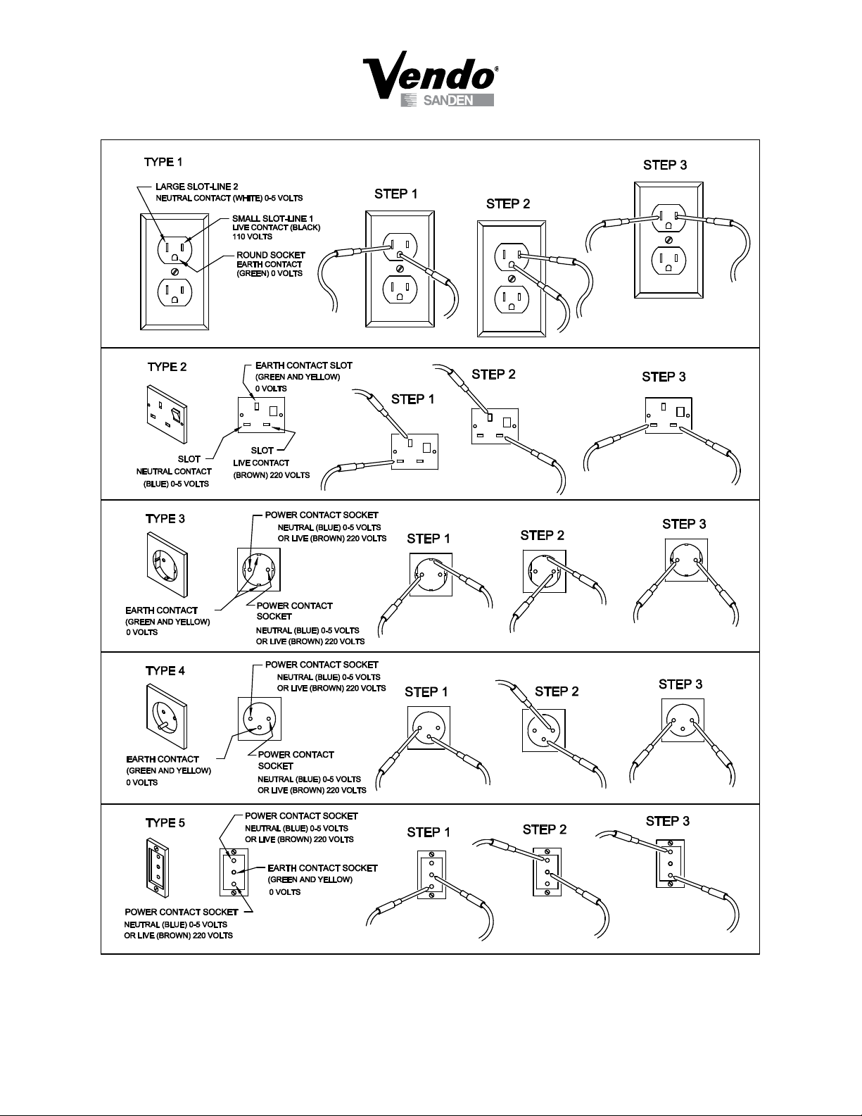
Test the outlets using the following information.
(Refer to Figure 1 on Page S-4.)
S-3
02/2008
S-4
02/2008

SECTION I: VENDOR INSTALLATION (CONTINUED)
For Type 1 and Type 2 outlets, test for Grounding and Polarization as follows:
1. With a test device (volt meter or test light), connect one probe to the receptacle’s
neutral contact and the other to the live contact. The test device should show a
reaction.
2. Connect one probe to the receptacle’s earth contact and the other to the live
contact. The test device should show a reaction.
For Type 3 through Type 5 outlets, test for Grounding as follows:
1. With a test device (volt meter or test light), determine which of the receptacle’s
power contacts is the live contact.
A. Connect one probe to the receptacle’s earth contact.
B. Connect the second probe to the left (or upper) power contact. If a
reaction occurs, this is the live power contact. If a reaction does not occur,
move the second probe to the right (or lower) contact. A reaction should
occur, indicating that this is the live power contact.
2. Connect one probe to the receptacle’s live power contact (as determined in step
1). Connect the second probe to the other power contact (neutral). The test
device should show a reaction.
IF THE ABOVE CONDITIONS ARE NOT MET FOR THE GIVEN OUTLET
TYPE, CONTACT A LICENSED ELECTRICIAN AND HAVE THE
NECESSARY CORRECTIONS MADE.
S-5
02/2008
SECTION II: ELECTRICAL HAZARDS
ALWAYS TEST TO VERIFY PROPER GROUNDING PRIOR TO
INSTALLATION TO REDUCE THE RISK OF ELECTRICAL
SHOCK AND FIRE
WARNING
GENERAL
SandenVendo America, Inc. vending machines are provided with the appropriate power
supply setting for your area. Some models are equipped with step-down transformers, as
required. This enables the vending machine to operate on different main voltages. Refer
to Section I. E. for information to determine the main power requirements. Refer to the
appropriate service manual for details of step-down transformer operations.
The power sources just mentioned are standard for both household and commercial
lighting and appliances. However, careless or improper handling of electrical circuits
can result in injury or death. Anyone installing, repairing, loading, opening, or otherwise
servicing a vending machine should be alerted to this point. Apply all of the normal
precautions observed in handling electrical circuits, such as:
• Refrigeration servicing to be performed by qualied personnel only.
• Unplug the vendor or move power switch to off position before servicing or clearing
product jams.
• Replace electrical cords if there is any evidence of fraying or other damage.
• Keep all protective covers and ground wires in place.
• Plug equipment into outlets that are properly grounded and polarized (where
applicable), and protected with fuses or circuit breakers.
• All electrical connections must be dry and free of moisture before applying power.
A. Grounding Systems
SandenVendo America, Inc. vending machines are provided with the appropriate
service cord for the power supply in your area. The service cord will connect to
the matching electrical outlet. Always ensure that the outlet to be used is properly
grounded before plugging in the vendor. (See pages S-3 through S-5.)
The electrical grounding system also includes the bonding of all metal components
within the vendor. This involves a system of bonding wires identied by green or green
and yellow marking. The system uses serrated head screws, lock washers, and star
washers to ensure the electrical connection between parts. Maintenance of vending
equipment may involve disassembly. Include the above items when reassembling, even
if the vending machine may appear to function normally without them. Omitting any
of these items can compromise a link in the grounding system. See the appropriate
service manual or kit instructions for components and assembly instructions.
S-6
02/2008
SECTION II: ELECTRICAL HAZARDS (CONTINUED)
“POWER ON” SERVICING SHOULD BE ACCOMPLISHED ONLY BY
FULLY-TRAINED PERSONNEL. SUCH SERVICE BY UNQUALIFIED
INDIVIDUALS CAN BE DANGEROUS.
WARNING
B. Servicing with “Power Off”
For maximum safety, unplug the service cord from the wall outlet before opening
the vendor door. This will remove power from the equipment and avoid electrical
and mechanical hazards. Service personnel should remain aware of possible
hazards from hot components even though electrical power is off. See the
appropriate sections of this manual for further information.
C. Servicing with “Power On”
Some service situations may require access with the power on. Power on servicing
should be performed only by fully-qualied service technicians. Particular
caution is required in servicing assemblies that combine electrical power and
mechanical movement. Sudden movement (to escape mechanical action) can
result in contact with live circuits and vice versa. It is therefore doubly important
to maintain maximum clearances from both moving parts and live circuits when
servicing.
Power to lighting and refrigeration system is shut off automatically by the electronic
controller when the outer door is opened.
NOTE: For power-on servicing of the vendor’s lighting system, turn lighting power
on by accessing the Lights test function of the electronic controller (see
programming on inner door).
For power-on servicing of the vendor’s refrigeration system, turn refrigeration
power on by accessing the Compressor test function of the electronic
controller (see programming on inner door).
S-7
02/2008
SECTION III: MECHANICAL HAZARDS
WARNING
RISK OF ENTRAPMENT!
RISK OF SHOCK!
ELECTRICAL!
WARNING
WARNING
THIS VENDING MACHINE INCLUDES MECHANICAL
EQUIPMENT WHICH CAN BE HAZARDOUS IF IMPROPERLY
HANDLED OR SERVICED. USE CAUTION AND CONSULT
THE VENDO SAFETY MANUAL AND VENDO SERVICE
MANUAL FOR ADDITIONAL SAFETY INFORMATION.
A. Servicing of Moving Parts and Assemblies
When servicing assemblies involving moving parts, use extreme caution!!
Keep ngers, hands, loose clothing, hair, tools, or any foreign material clear of
entrapment.
As noted before under the electrical hazards section, Power On servicing should
only be performed by qualied personnel. Refer to and heed the warnings noted
in the electrical hazards section. These warnings refer to the potential hazards
associated with electrical power and moving parts. Always maintain maximum
clearances from electrical and moving parts.
Always install protective covers and guards when reassembling equipment.
S-8
02/2008
SECTION IV: REFRIGERATION HAZARDS
ALWAYS WEAR EYE PROTECTION AND PROTECT YOUR
HANDS, FACE, AND BODY WHEN WORKING NEAR
THE REFRIGERATION SYSTEM
WARNING
GENERAL
Refrigeration systems involve both electrical power and mechanical action. These
systems may present any of the potential dangers shown in the sections on electrical
and mechanical hazards contained in this manual. See Sections II and III for further
information.
A. Compressed Refrigerant
Refrigeration systems involve the compression and evaporation of gases. The
pressures contained represent a potential hazard if suddenly released in conned
areas. Caution is required when performing maintenance tests or repairs. All
testing of sealed refrigeration systems must be done by trained personnel who are
familiar with the systems and pressures involved.
B. Physical Protection
The accidental release of refrigerant gases can result in physical injuries. Always
wear protective glasses and protect your hands, face, and body when working
near the refrigeration system.
SECTION V: TEMPERATURE HAZARDS
GENERAL
Maintenance personnel should be alerted to the potential hazards from hot metal
surfaces. High temperatures may be present throughout the refrigeration system even
though electrical power has been removed.
S-9
02/2008
SECTION VI: SUBSTITUTIONS AND MODIFICATIONS
VENDO EQUIPMENT HAS BEEN PROVIDED WITH APPROPRIATE PROTECTIVE
DEVICES TO PROTECT AGAINST THE POSSIBILITY OF OVERHEATING AND
FIRE AS A RESULT OF EQUIPMENT OR COMPONENT FAILURES.
SUBSTITUTION, MODIFICATION, OR BYPASSING OF SUCH PROTECTIVE
DEVICES CAN CREATE DANGEROUS CONDITIONS. PROTECTIVE CIRCUITS
SHOULD NEVER BE BYPASSED, AND FAILED PROTECTIVE DEVICES MUST
BE REPLACED ONLY WITH FACTORY-AUTHORIZED
PARTS.
WARNING
GENERAL
Unauthorized changes or the substitution of unauthorized parts can compromise the
equipment designs. This can result in unsafe conditions for either the service personnel
or the equipment users. Always refer to the appropriate parts and service manual for
replacement parts and maintenance instructions. If questions arise, contact the Technical
Services Department of the SandenVendo America, Inc. ofce in your area.
When servicing the vending machine, always reassemble all components to their original
location and position. Maintain the correct routing for tubing, electrical wiring, etc..
Replace all clamps, brackets, and guides to their original locations. Replace all tubing,
sleeving, insulating material, and protective covers to their original condition
A. Service Cord Replacement
SandenVendo America, Inc. vending machines are furnished with unique power
supply cords. If replacement becomes necessary, consult the appropriate parts
and service manual and order the correct replacement cord for the model of
vending machine in question. Do not use substitute replacement cords. Only
authorized service personnel with appropriate training should replace the vending
machine service cord. If a question should arise concerning which service cord to
order, contact the Technical Services Department of the SandenVendo America,
Inc. ofce in your area.
S-10
02/2008
SECTION VI: SUBSTITUTIONS AND MODIFICATIONS (CONTINUED)
THIS APPLIANCE MUST BE EARTHED.
IMPORTANT!
WARNING
The wires in the main leads are colored in accordance with the following code:
110v/120v 220v/240v
Green Green and Yellow ............................. Earth
White Blue ................................................... Neutral
Black Brown ................................................ Live
S-11
02/2008
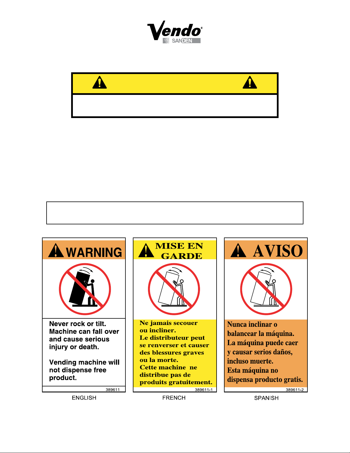
SECTION VII: CONSUMER SAFETY WARNING
VENDOR CAN BE OVERTURNED IF SUFFICIENT FORCE IS
APPLIED AND MAY RESULT IN SERIOUS INJURY OR DEATH.
WARNING
GENERAL
There have been incidents, including fatalities, when vending machines have been
vandalized by being pulled over in an attempt to obtain free product or money.
To warn of the danger involved in tipping, shaking, or rocking the vending machine, a
decal has been designed to be afxed to vending machines. (One such decal is applied
on the vending machine.) SandenVendo America, Inc. will supply sufcient decals to be
placed on all machines, on request. If you have any questions, contact the Technical
Services Department of the SandenVendo America, Inc. ofce in your area.
THE FOLLOWING DECAL SHOULD BE PLACED IN A POSITION
ON THE VENDOR CONTROL PANEL AT EYE LEVEL
S-12
02/2008
SECTION VIII: PARTS, SALES, & SERVICE CENTERS
OF SANDEN COMPANY
AREA ADDRESS PHONE NUMBERS
United States,
Canada
Japan Sanden International Corporation
Europe, Mid-East
Africa, Mid-Asia
Australia,
New Zealand
Singapore,
Hong Kong,
Indonesia,
Phillippines, India
Taiwan Sanden International Taiwan Corp.
Belgium N.V. Vendo Benelux, S.A.
England Vendo UK Ltd.
Italy Vendo Italy S.p.A.
Spain Vendo Iberia, S.A.
SandenVendo America, Inc.
10710 Sanden Drive
Dallas, TX 75238-1335 U.S.A.
31-7 Taito 1-Chome
Taito-ku
Tokyo 110, Japan
Vendo GMBH
Spangerstr. 22, P.O. Box 130940
40599 Dusseldorf
Germany
Sanden International Pty. Ltd.
54 Allingham St., Condell Park
N.S.W. 2200
Australia
Sanden International (Singapore) Pte., Ltd.
Sanden House, 25, Ang Mo Kio St. 65
Singapore 569062
The Republic of Singapore
No, 21-6, Sec 1
Tun Hwa S. Rd., Taipei, Taiwan
Taiwan, ROC
Industrial Research Park N.O.H.
13 Font St. Landry
1120 Brussels
Belgium
Vendo House
Kingsclere Road
Basingstoke, Hants RG21, 5GU
Great Britain
Casella Postale 9
1-15033 Casale Monferrato
Italy
C/ Sant Ferran No. 92
Poligono Industrial la Almeda, Sector P-1
08940 Cornella, (Barcelona), Spain
Tel: (800) 344-7216 ext.
3368
Fax: (800) 541-5684
Tel: (81) 3-3835-1321
Fax: (81) 3-3833-7096
Tel: (49) 211-74-039-0
Fax: (49) 211-7488541
Tel: 61-2-9791-0999
Fax: 61-2-9791-9029
Tel: 65-482-5500
Fax: 65-482-1697
Tel: 886-2-570-6106
Fax: 886-2-577-1959
Tel: 32-2-268-2595
Fax: 32-2-268-2862
Tel: 44-1256-479309
Fax: 44-1256-844469
Tel: 39-142-335111
Fax: 39-142-5623-48
Tel: 343-474-1555
Fax: 343-474-1842
S-13
02/2008
SECTION IX: PARTS, SALES, & SERVICE CENTERS OF
SANDEN COMPANY FOR LATIN AMERICA
AREA ADDRESS PHONE NUMBERS
Mexico Vendo de Mexico
Camino Real de Toluca No. 154
Col. Bellavista
01140 Mexico D.F. Mexico
Central America SandenVendo America, Inc.
10710 Sanden Drive
Dallas, TX 75238-1335 U.S.A.
Chile Pelp Internacional, S.A.
4560 El Rosal
Huechuraba, Santiago, Chile
Brazil Cimaq Industria e Comercio de Maq, Ltda.
Estrada Uniao e Industria, 9.120 Itaipava
25730-730 Petropolis
Rio de Janeiro, Brazil
South America SandenVendo America, Inc.
10710 Sanden Drive
Dallas, TX 75238-1335 U.S.A.
Tel: (525) 515-9745
Fax: (525) 277-0111
Tel: (800) 344-7216 ext.
3368
Fax: (800) 541-5684
Tel: (562) 243-9710
Fax: (562) 740-0504
Tel: (55242) 22-2666
Fax: (55242) 22-3244
Tel: (800) 344-7216 ext.
3368
Fax: (800) 541-5684
S-14
02/2008

NOTES
S-15
02/2008

Glass Front Snack Vendor
VS 411 and VSR 411
GENERAL INFORMATION
SECTION
G-1
08/2005
General information
1.0 Introduction
This service manual covers the VS411 and the VSR411 Snack Vending Machine.
This manual is designed to act as a reference for service technicians.
We recommend that you study this manual as there are many features and uses.
If you do not understand any part of this manual please contact The SandenVendo
America, Inc. Technical Service Department at (800) 344-7216 ext 3368.
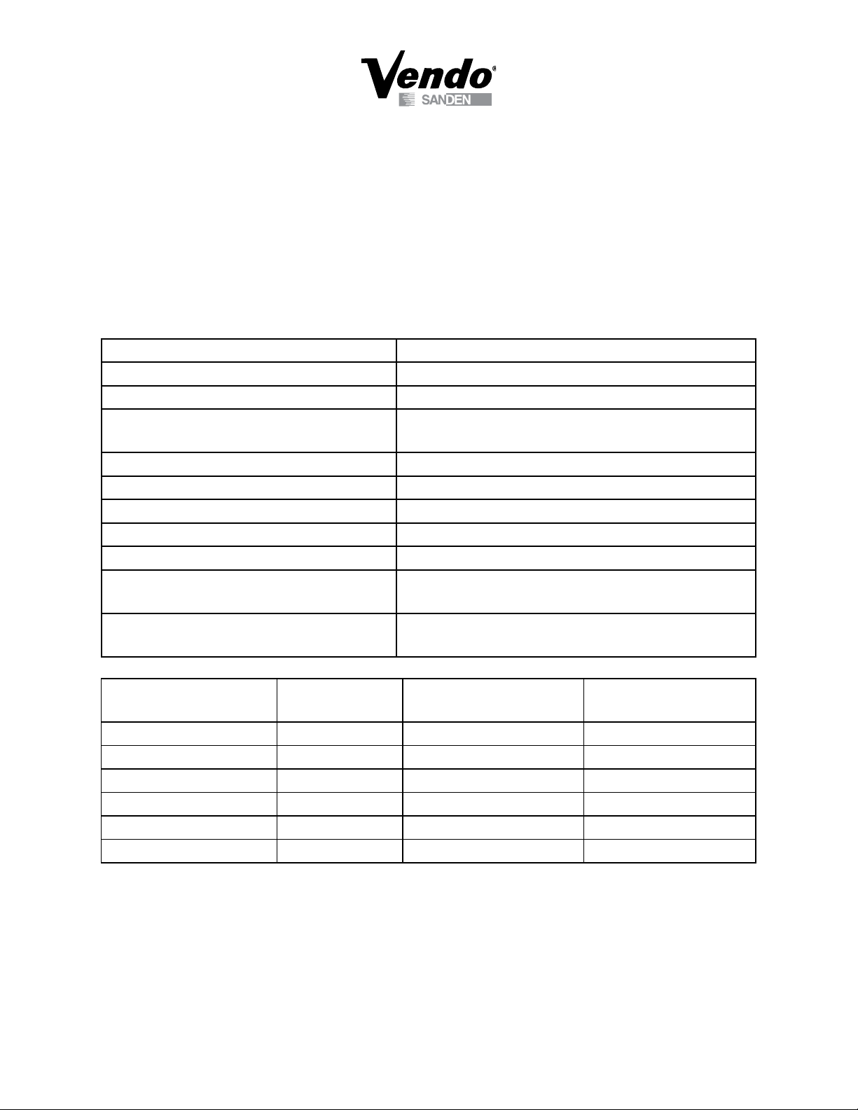
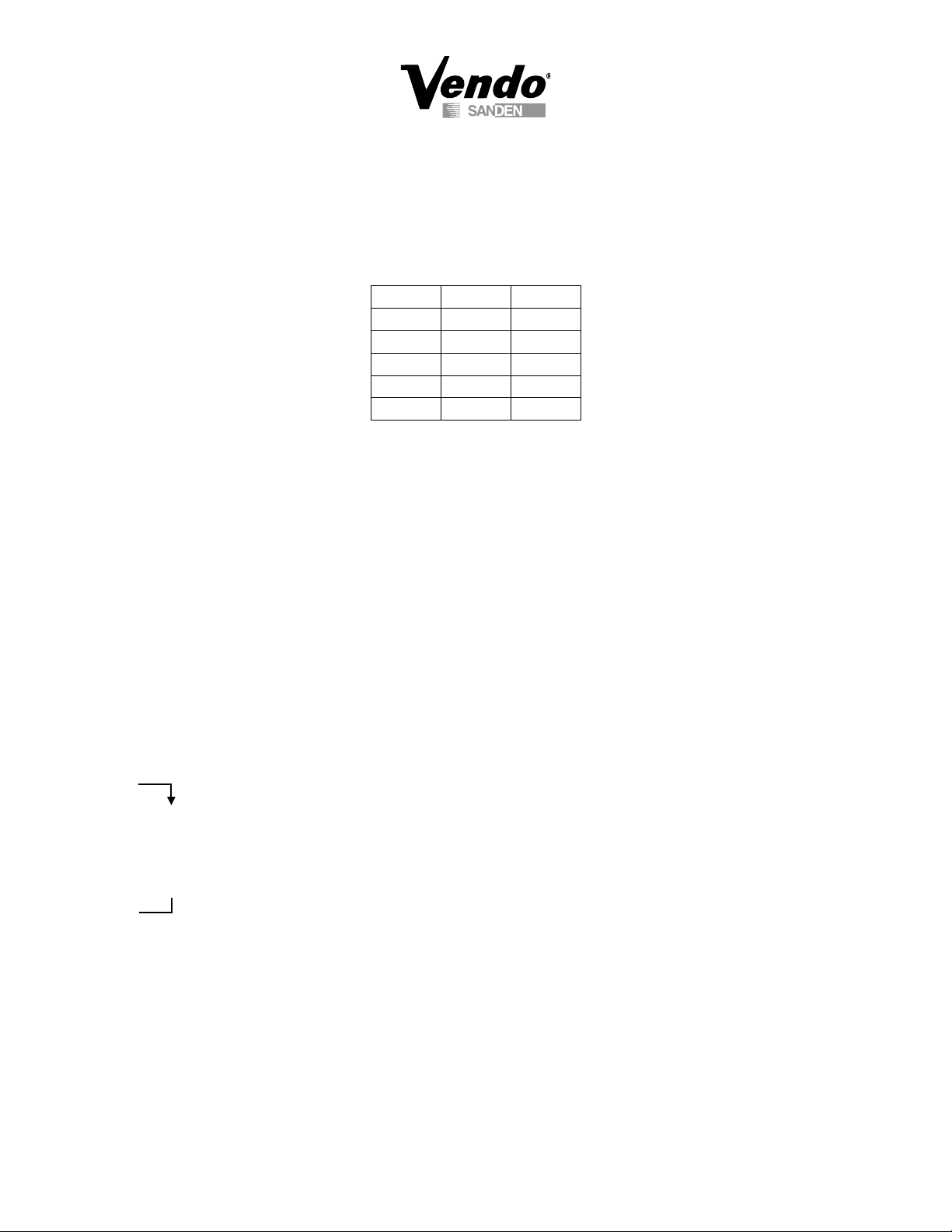
1.1 Machine specications
Product Name Glass Front Snack Vending Machine
Product Type VS-411 & VSR-411
Location Environment Inside only
Outside size inch (mm)
72 x 37 x 28 (1830 x 940 x 720)
(Length x Width x Depth)
Weight lbs (kg) Net weight 661.35 (300)
Adjustment scope for screw inch (mm) .79 (20)
Voltage (v) 115 +10%/-15%
Frequency (Hz) 60
Nominal current (A) VS-411 (0.6) & VSR-411 (8.5)
Product capacity Followed by owner’s needs (note: for normal
product capacity, please see list below)
Refrigeration Temperature Environment Temperature ≤ 104°F (40°C),
Temperature Inside of machine ≤ 77°F (25°C)
Tray position
(Black Color)
Product
tray
# of Products
per Chute
A 4 product tray 8 32
B 4 product tray 10 40
C 8 product tray 10 80
D 8 product tray 12 96
E 8 product tray 14 112
F 8 product tray 18 144
G-2
# of Products
per Tray
08/2005
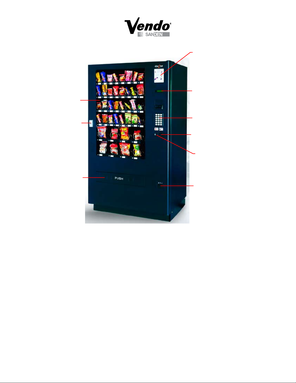
Instruction Window
LCD
Keypad
Coin Return Button
Coin Entry
Vend Hopper
Door Lock
Glass
Coin Return Door
1.2 Principle operation
When coins or bills are inserted, the identication system will identify the bills and coins;
then the amount of money will appear in the LCD window. Press the key pad to choose
the goods you want to purchase. Then machine will drive the selected products to the
vend hopper. If there is still some change left, you can continue purchasing. If you don’t
want to purchase anything more, press the coin return button to get the change. If no
other products are selected within a 30 second period, the change will be automatically
returned.
1.3 Startup
1. Open the door of the machine, connect the power, and turn on the power switch.
2. Fill coin mechanism with change.
3. Fill all the products into the trays one by one (See 1.7 Filling Operation).
4. Install the price label (See 1.8 Price Label Layout).
5. Set up the machine control system as per the customers’ requirements (See the
Programing Section of the manual).
6. Lock the door of the vending machine. The vending machine is ready for use.
G-3
08/2005
1.4 Purchase Product
$
A
C
D
1
4
7
*
F
2
3
5
6
8
9
0
#
B
E
$
1. Insert Money
2. Choose Product 3. Coin Return
4. Take Out Change
5. Remove Product
1
2
3
4
Diagram 1
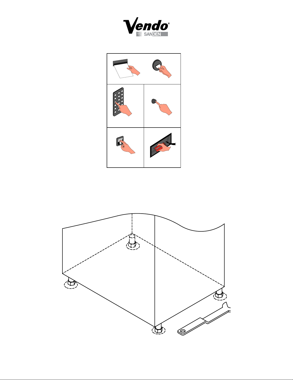
1.5 Installation Requirements
1.5.1 Ensure the machine is level, and adjust the screws on the feet as below (diagram
2). A level machine will ensure that the door automatically stays in any position
when it is open.
Diagram 2
G-4
08/2005
1.5.2 Make sure the machine has enough space in the front and at the door axis side to
1
2
3
4
let the door open enough.
1.5.3 The distance between the wall and the back of the vending machine should be
more than 15cm (5.9 inches) to ensure a good air ow, otherwise the function of
chiller will be affected and may not work properly.
1.5.4 Put the machine on at and stable ground. Prevent water splash on the
machine and avoid leakage that may harm people after raining. Keep away from
heat source. Avoid direct sun light and put in a place where there is good air
conditioning.
1.5.5 The power supply must be 115V/60Hz and the rated supply current should be
more than 16A. The ground wire must connect with ground to prevent shock,
and to prevent electromagnetic interference caused by static electricity. All wire
connections must be made by a professional electrician.
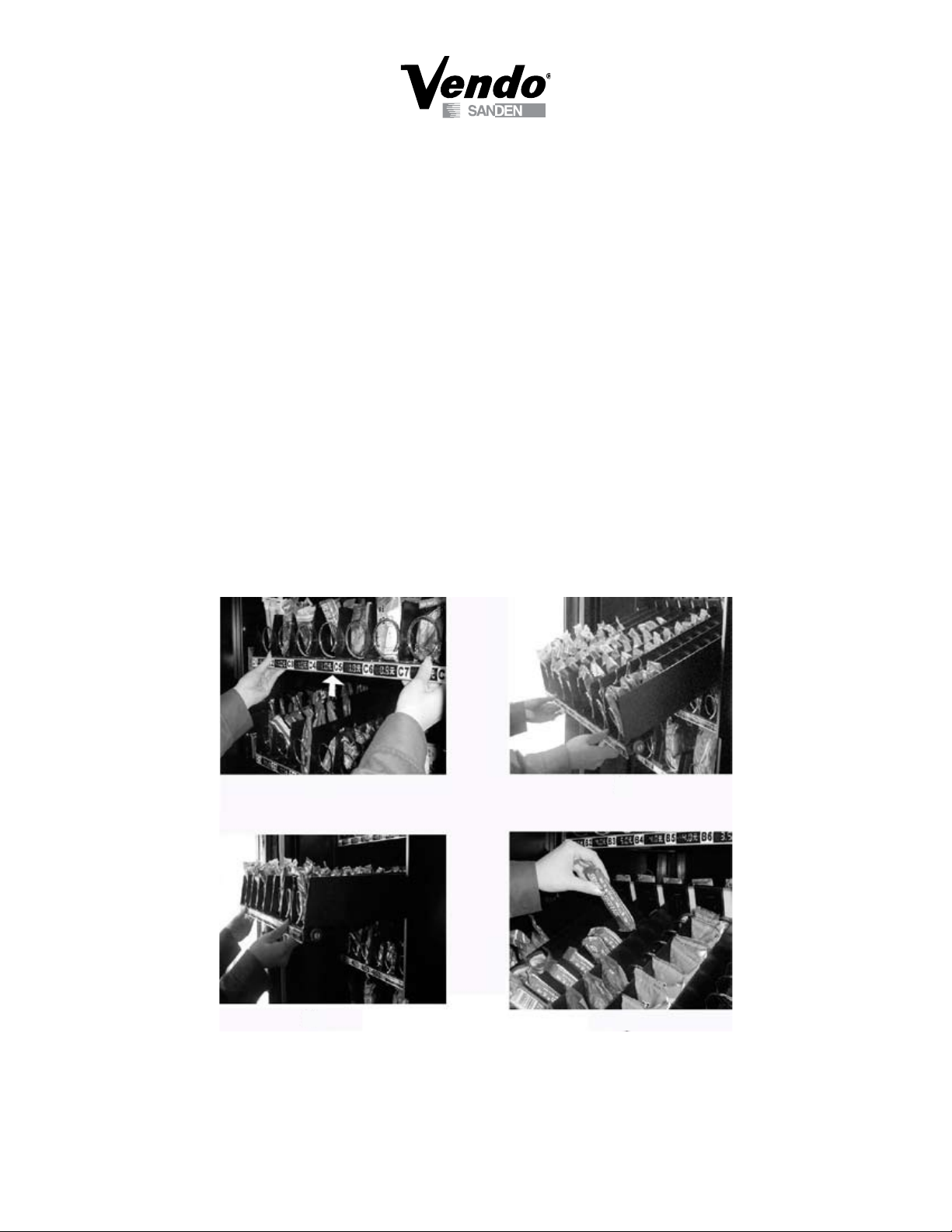
1.6 Filling Operation
Open the door to the maximum position. Lift up the tray approximately 30mm (1.18
inch), and then pull it out to the stop position. There should be only one tray in the lling
products position at a time. When pushing the tray back, it must be pushed back to the
original position as shown in (diagram 3).
Diagram 3
When lling products, don’t force them into the spiral. Products should be put in freely.
If there is not enough space for it to move, it will get jammed, and the consumer won’t
G-5
08/2005
get the product. If you nd the product does not t loosely in the spriral, select a bigger
spiral.
For plastic packaged products, we suggest folding the bottom of the product, before
putting it into the tray in order to prevent product jamming as shown below (diagram 4).
Diagram 4
When lling products, please try to put all products to lean in the same direction.
When lling products, please notice the height of the product to avoid jamming between
two trays.
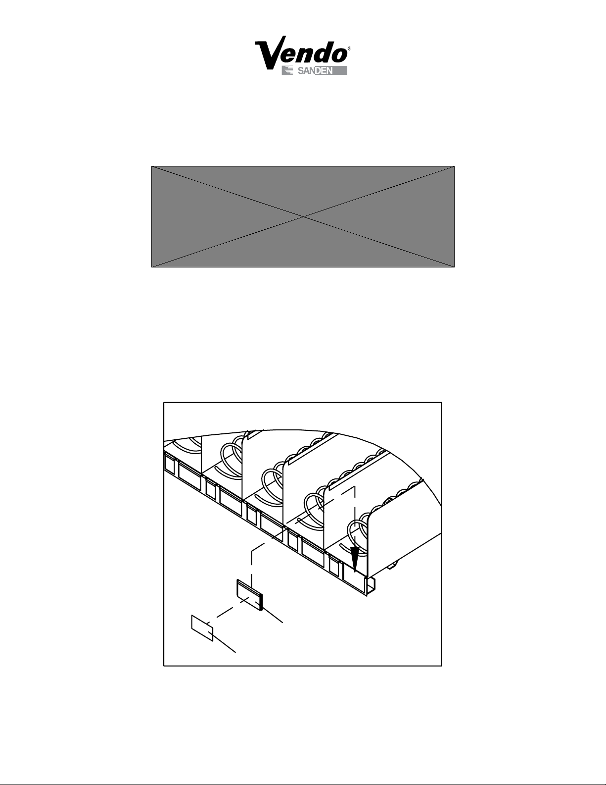
1.7 Price Label Layout
Put the price label into shelf strip insert as shown (diagram 5).
A
4
1
.
0
0
A
5
1
.
0
0
A
6
1
.
0
0
A
7
1
.
0
0
A
8
1
.0
0
Shelf Strip
Price Label
Diagram 5
G-6
08/2005
1.8 Routine Maintenance
1.8.1 Use soft cloth dipped in detergent to clean the bill entry chute. This will help to
prevent dust from affecting the bill identication mechanism.
1.8.2 Use soft cloth dipped in detergent to clean the coin entry chute. This will help to
prevent coins from sticking on the chute affecting the normal working process.
1.8.3 Ensure the tray, vend hopper, and key pad are clean.
1.8.4 Once the power is connected, do not remove the plug, otherwise data will be lost
and it will even damage other electric components.
1.8.5 Do not place goods around the evaporator in the cabinet, as this will affect the
function of the chiller and cause problems.
1.8.6 Liquids are to be prohibited from contacting the electrical parts and the
mechanism on the Bill Validator or Coin Mechanism.
1.8.7 Use soft cloth dipped in detergent to clean the glass and the surface of the
machine.
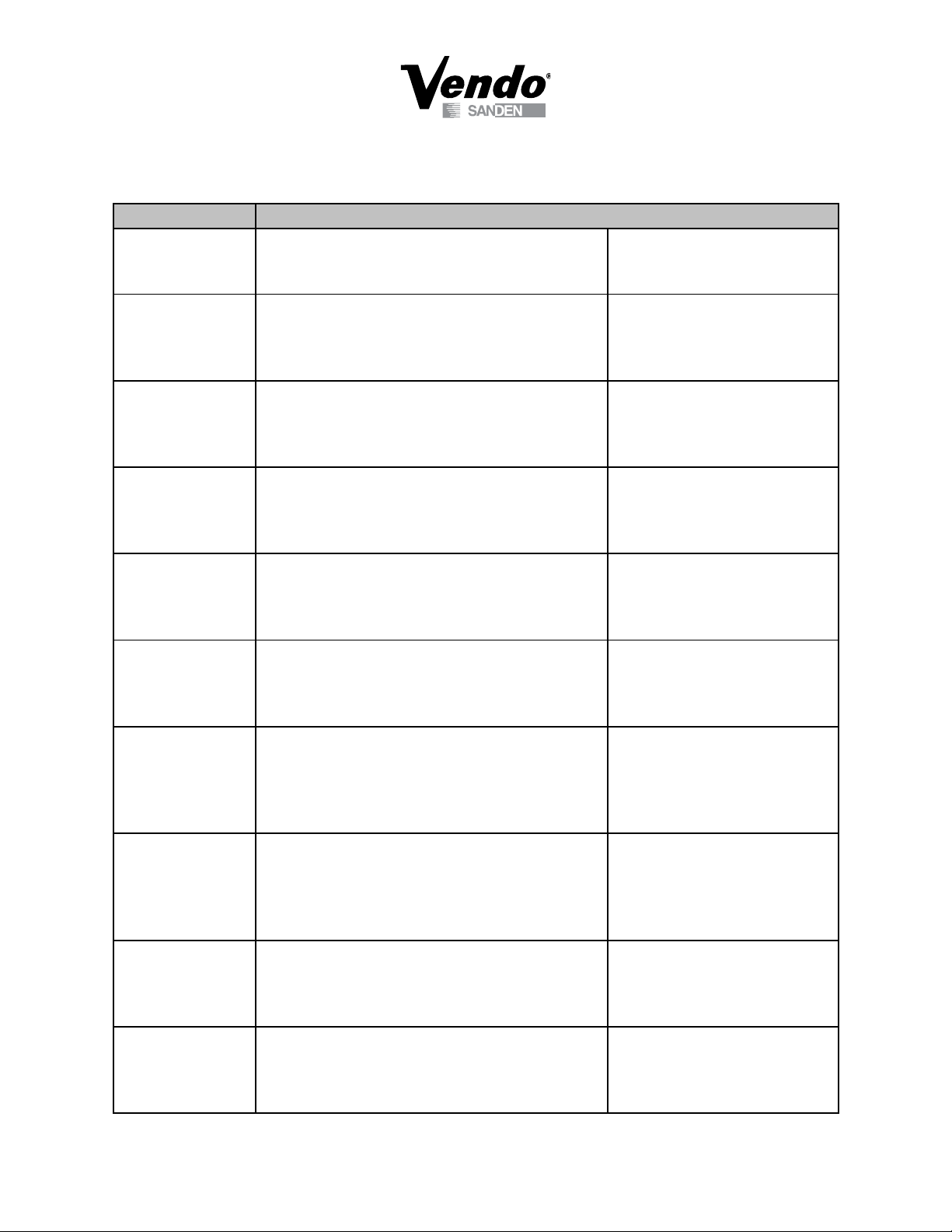
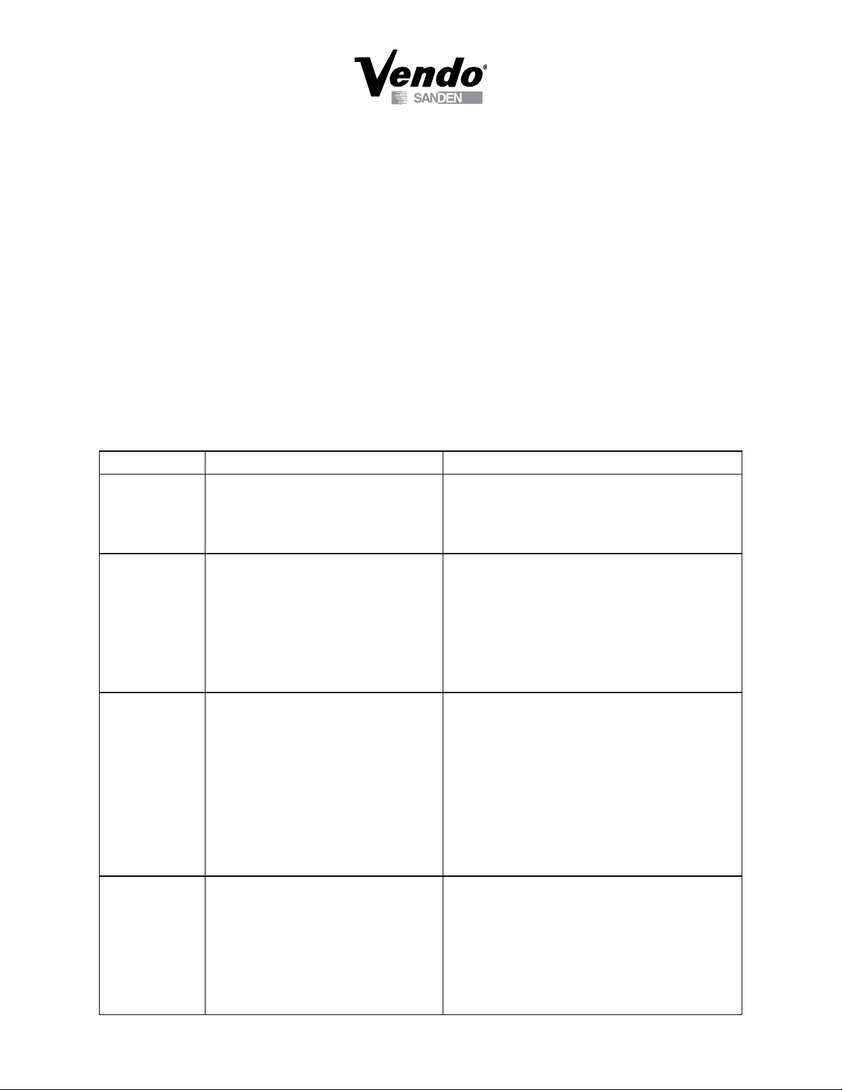
1.9 Troubleshooting
Problem Reasons Solution
Does not
accept bills
Does not
accept coins
Incorrect
change given
Correct change
given, but no
product was
given
1. Changer out of change
2. Foreign material inside of Bill Validator
3. Money is incorrect
4. Plugs are loose
5. Bill Validator is damaged
1. Change is incorrect
2. Indicator of Coin Mechanism (CM) is
not working
3. Coin jam or dust in the CM
4. Jam on electromagnetic distribution
brake
5. Indicator of CM is designating an error
6. Water got into CM
7. CM damaged
1. Coins incorrectly lled
2. Control board didn’t adjust into the
correct position for returning change
3. Coin return pole of CM got jam
4. The address of the CM is not correct
5. Label price and setting price are not
matched
6. CM is damaged
7. Coin return mechanism is in the wrong
position
1. Spiral jamming
2. Spiral didn’t return to the same position
3. Mistakingly chose the empty chute
4. Incorrect product lling
1. Correctly ll up coins
2. Clean the Bill Validator
3. Use correct money
4. Reinstall the connector after turning off the power
5. Change to a new one
1. False coin can not be accepted, use correct
currency
2. Check if the power and plug are loose
3. Open up the machine to clean CM
4. Use small tool to remove the jammed components
5. Check low level transducer, use Alpha to delete all
the faults by adjusting 349 address to 1
6. Take out the CM ,use dryer to dry it
7. Change to a new one
1. After resetting, ll coins correctly
2. Adjust into the correct change status otherwise no
change will return or less change will return.
3. Check the part that got jammed. Check the
reposition status of each coin return pole, (press
button MODE twice, each pole returns to front
automatically)
4. Adjust each position or change
5. Reset price carefully to match
6. Change to a new one
7. Check and correct the coin return mechanism
position
1. Cleanup and reposition it to let the motor turn one
cycle
2. Take out the spiral to adjust it to the original
position
3. Adjust the price of empty chute to “0” or the highest
price or ll the chute
4. Choose correct products for the spiral. If the
dimension of the products is smaller than 2/3 of the
spiral diameter, they will cause a jam
G-7
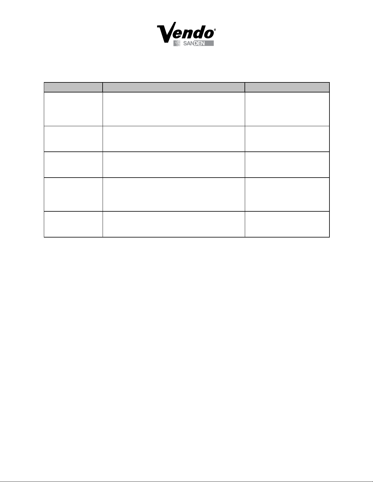
08/2005
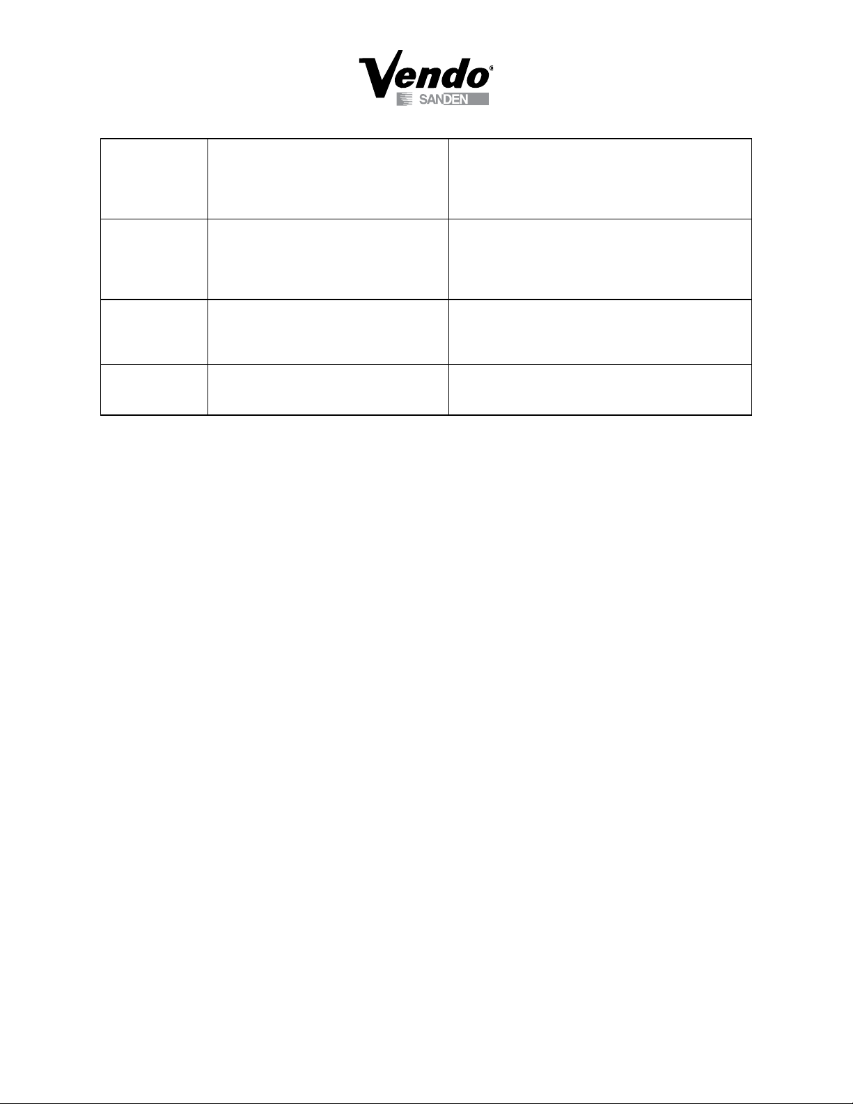
Products in the
chute,
but does not
sell
Refrigeration
Compressor has
no
refrigerating
effect
The door can
not be locked
Products
continue to go
out
1. The price of product is higher than the
inserted money
2. Vend motor failure
1. Air ow hatch got jammed
2. The position of thermostat is not correct
3. Low on refrigerant
1. The machine is not leveled.
2. The distance between Lock and Lock
socket is long.
1. Selling products mechanism has
problems
1. Continue to insert money until it is enough or more
than the product price
2. Test motor by swapping motor connection with
another motor. If that motor works, replace the
defective motor.
1. Clean it up, position the rear of the machine 15cm
(5.9 inch) from the wall.
2. Adjust the controller into the right position
3. Find professional refrigeration maintenance person
to replace or add refrigerant.
1. Level the machine, adjust the screw under the lock
one pitch lower than other three screws
2. Loosen the door lock mounting nut, adjusting it up
and down until you can close the door easily
1. Check the motor position switch whether it works
normally, if it works normally, then it is the control
board’s problem, change to a new one.
G-8
08/2005

NOTES
G-9
08/2005

Glass Front Snack Vendor
VS 411 and VSR 411
PROGRAMMING SECTION
P-1
08/2005
Control Board Programming
1.0 Overview
The Vending Machine Controller (VMC) tted to the 411VS & 411VSR is known as the MCB560. This is
similar in design and operation to the unit tted to the MARS SERIES 2000 BRANDED VENDOR (MDB
board interface).
A maximum of 60 selections are made via a matrixed keypad ("A" – "F", "1" – "9", "*", "0", "#"), where a
product selection is made by pressing one letter and one numeric key.
A B C
D E F
1 2 3
4 5 6
7 8 9
*
The VMC may be programmed using one of the following methods
1) Manual programming is performed with the door open using the mode switch (located on the VMC)
and the selection switches.
2) Automated programming is performed by uploading conguration and/or price information from the
DEX/UCS hard wired interface.
1.1 Programming Guide
All programming is performed using the selection keypad. The board provides two interface modes - sales and service.
Sales mode is accesed by pressing and holding the door switch for 5 seconds when the door is open. The service
mode is accessed by pressing the mode switch on the VMC (the door must remain open while in service mode). Once
in service mode the "#" key is used to scroll through the service modes. The available service modes are listed below.
0 #
1.1.1 Sales Mode
Once in Sales Mode, total sales per machine, per shelf, or per spiral can be viewed.
1.1.2 Service Mode
In Servie Mode, press the number key to scroll through each mode as indicated below. For an overview of
the Service Mode, see page P-17.
1.1.3 Setup/tube Ctl
1.1.4 Set Price
1.1.5 Machine Test
1.1.6 Mis/history/errors Display
1.1.7 Entry Code/password
Additionally, Engineer service modes are accessible by entering the correct 4 digit password. The
additional service modes are listed below.
1.1.8 Space To Sales (Sts) Programming
1.1.9 Display Programming
1.1.10 Machine Resets
1.1.11 Set Time Functions
1.1.12 Set Mis Access
1.1.13 Motor Pairing
The default password is “3142”.
Appendix 1 lists all VMC parameters, and their default settings.
P-2
08/2005
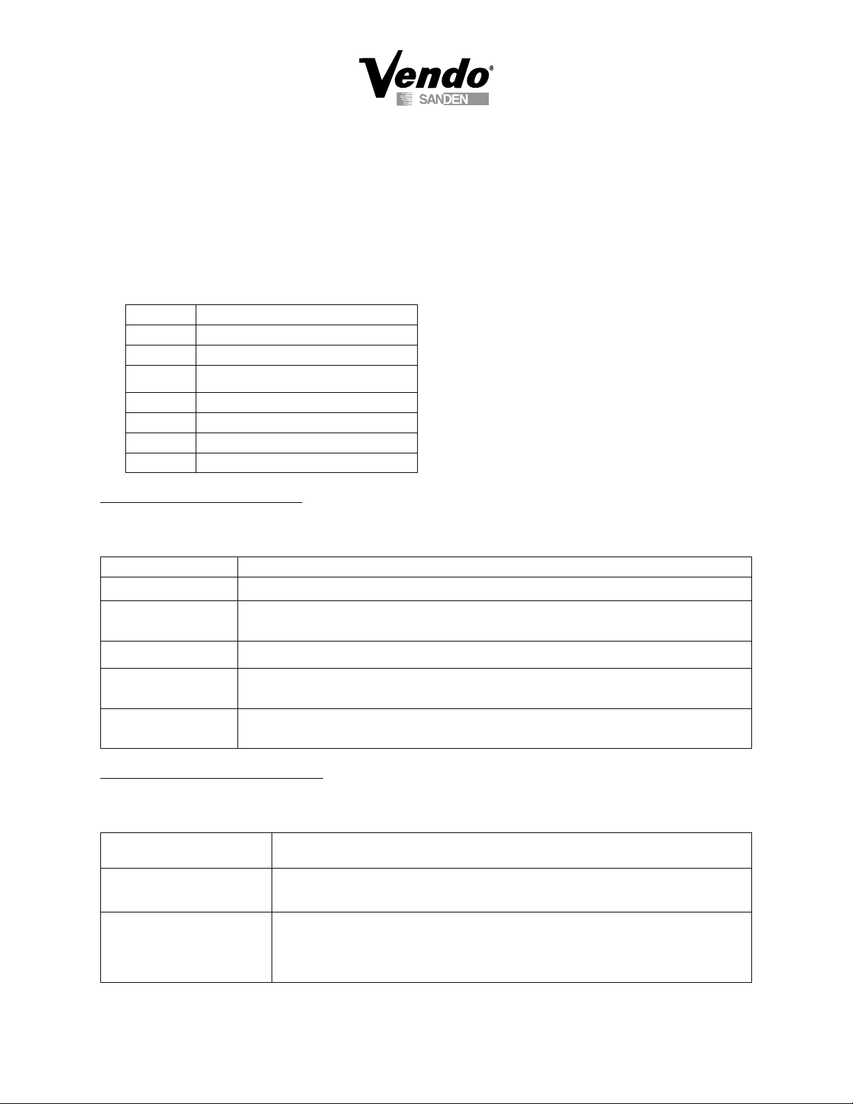
1.1.3 Setup/tube Ctl (Service Mode 1)
This mode is rst accessed when the VMC mode switch is pressed.
This service mode is used to perform the following actions:
Congure the machine
Dispense coins
Select the type of coin mech used
Display the coin tube inventory
Setup the overpay feature
Set/clear the vend detector present ag
Each of these options is set by repeated presses of the same button.
Button Option
A Cash Handling
B Change Handling
D, E,
1, 2
Coin dispense (MDB only)
7 Coin tube inventory display
8 Single/multi price
* Set overpay value
0 Vend detect sensor tted
BUTTON “A”, CASH HANDLING
Pressing button "A" will display the present mode of cash handling. Repeated presses of the button scrolls
through the different types of cash handling.
CASH HANDLING DESCRIPTION
Force Vend
Force Bill/Coin
Change Machine
Neutral
No Change
No escrow return unless a selected product is sold out.
If a bill is stacked or a non tubed coin is accepted, then a selection must be
made.
Bills are always stacked. Escrow Return always returns the credit.
Except that the rst bill is held in escrow, the mode is the same as “Change
Machine”
Change is never paid out. The machine operates with a bill acceptor only or
with a tubeless coin mech.
BUTTON “B”, CHANGE HANDLING
Pressing button "B" will display the present mode of Change Handling (Multi/Normal Vend). Continued
presses of the button, toggles between the different types of change handling.
CHANGE HANDLING
MODE
DESCRIPTION
Change is paid out after the VMC detects the delivery of product (if the Vend
Normal Vend
Detect beam is used) or after the motor leaves home (no Vend Detection
used)
If the remaining credit (after a vend) is >= to the minimum Vend price, the
Multivend
credit will not automatically be returned at the end of the vend. A customer
can add additional credit, buy another product, or retrieve the credit. The
credit is automaticly returned after 20 seconds.
P-3
08/2005
 Loading...