

Page 1
Operating Instruction
VEGASON 51 V … 53 V
Level and Pressure
Page 2

Contents
Safety information ........................................................................... 2
1 Product description
1.1 Function ................................................................................... 4
1.2 Application feature .................................................................. 5
1.3 Adjustment ..............................................................................6
2 Types and versions
2.1 Survey ..................................................................................... 9
2.2 Configuration of measuring systems .................................. 12
3 Technical data
3.1 Data ....................................................................................... 17
3.2 Approvals ............................................................................. 20
3.3 Dimensions ............................................................................. 21
Contents
Safety information
The described module must only be installed
and operated as described in this operating
instruction. Please note that other action can
cause damage for which VEGA does not take
responsibility.
2 VEGASON 51 V … 53 V
Page 3

Contents
4 Mounting and installation
4.1 General installation instructions ........................................... 23
4.2 Measurement of liquids ........................................................ 2 5
4.3 Measurement of solids ......................................................... 28
4.4 Socket extensions ................................................................ 30
4.5 Flow measurement ............................................................... 31
4.6 False echoes ......................................................................... 32
4.7 Installation error .................................................................... 35
5 Electrical connection
5.1 Connection and connection cable ....................................... 38
5.2 Connection of the sensor ..................................................... 3 9
5.3 Connection of an external indicating instrument
VEGADIS 50 ......................................................................... 40
6 Set-up
6.1 Adjustment structure ............................................................ 41
6.2 Adjustment with PC on VEGAMET ...................................... 42
6.3 Adjustment with VEGAMET or MINICOM ........................... 59
6.4 Adjustment with PC on VEGALOG ...................................... 72
VEGASON 51 V … 53 V 3
Page 4
1 Product description
1.1 Function
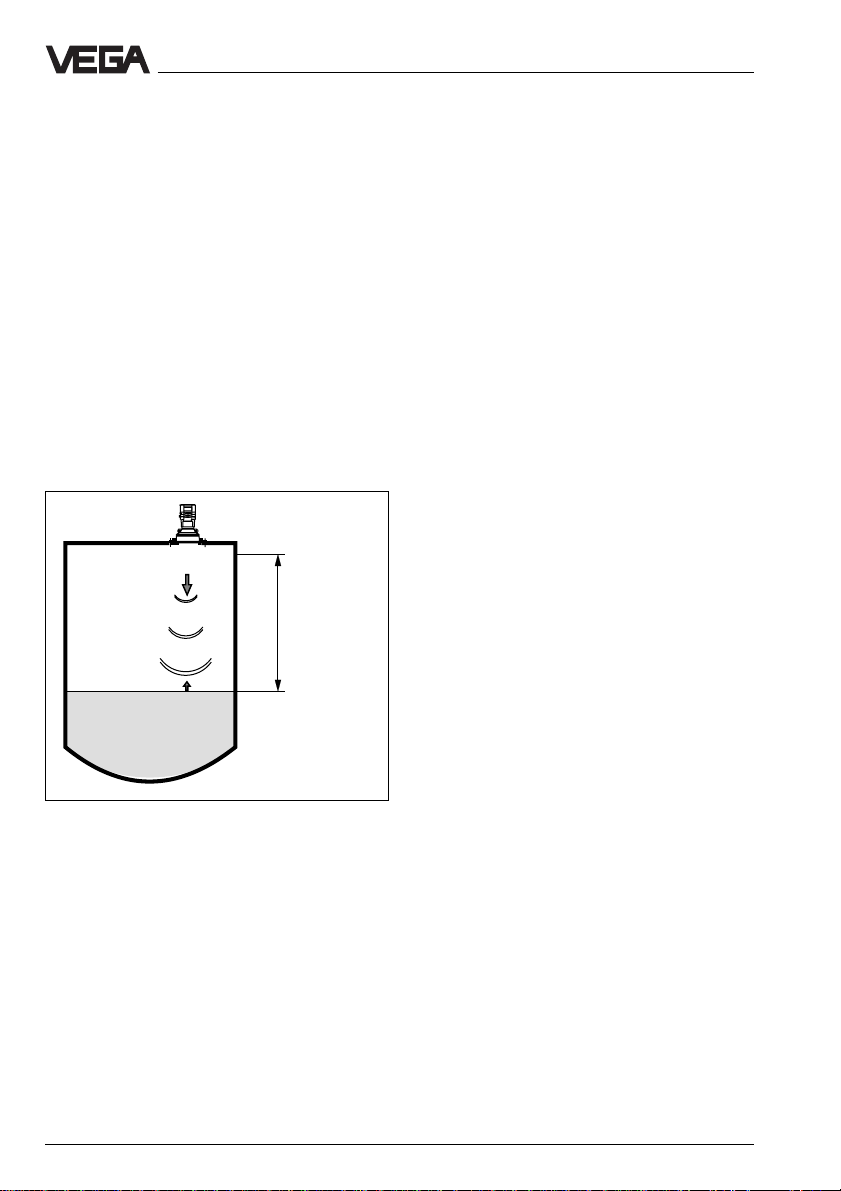
The continuous level measurement with ultrasonic sensors is based on the running time
measurement of ultrasonic pulses.
Measuring principle:
Piezoceramic high-performance transducers
emit focussed ultrasonic pulses reflected
from the surface of solids and liquids. The
meas. signal prepares a precise picture of
the meas. environment out of the running time
and signal shape of the reflected ultrasonic
pulses. The transducers operate as emitter
and receiver. As receiver the transducers are
high sensitivity piezomicrophones.
Meas.
distance
Product description - Function
Out of the physical sound velocity and the
detected actual running time of the emitted
sound impulses, the meas. electronics calculates precisely the distance between transducer and product. The distance is converted into a level proportional meas. signal
and provided acc. to the sensor parameter
adjustment as exact scaled level. The instruments operate with emitting frequencies from
34 kHz to 70 kHz to be prepared for the
different distances and requirements.
As the sound velocity is subjected to a temperature influence, the transducer detects
continuously the ambient temperature so that
the level is provided precisely even with
varying ambient temperature.
emission - reflection - receipt
4 VEGASON 51 V … 53 V
Page 5

Product description - Application feature
Output signal
The level proportional meas. signal is either
processed in the ultrasonic instrument itself
or in the connected signal conditioning instrument and provided as output signal.
In digital technology varying line resistances
or smallest leakage currents have no influence to the accuracy. The digital signal is
always clear.
Individual parameter adjustment of the digital
signal is possible and the signal always reflects the adjusted meas. range of the sensor.
Measured value indication
An indicating instrument for direct, local level
survey is integrated in the series 50 ultrasonic sensors. The indicating instrument
shows with the analogue bargraph immediately the level and with the digital figure value
precisely the level. Additionally to the indication in the sensor, the level can be indicated
with the external indicating instrument
VEGADIS 50 separated up to 25 m from the
sensor.
The external measured value indication like
the integral indication works completely independent from the output signal and individual
parameter adjustment is possible.
1.2 Application feature
Applications
• Level measurement of liquids
• Level measurement of solids
(only short meas. distances) such as
e.g.:
coal, ore, stones, stone dust, cement,
gravel, crushed stones, sand, sugar,
salt, cereals, flour, granules, powder,
dusts, saw dust, wood chips
• Flow measurement on various flumes
• Gauge measurement, distance measurement, object monitoring and conveyor belt monitoring
Two-wire technology
• Supply and output signal on one twowire line (loop powered)
• Output signal and signal processing
completely digital
Rugged and precise
• Unaffected by product features such
as density, conductivity and dielectric
constant figure …
• Suitable for aggressive substances
• Meas. ranges 0,25m…15m
• Precise due to digital measured value
processing and transmission
Adjustment choice
• With adjustment software VEGA Visual
Operating (VVO) on PC
• With detachable adjustment module
MINICOM
• With signal conditioning instrument
VEGAMET
• Measured value indication integrated
in the sensor
• Optionally indication separated from
the sensor
Connection for each process
•G 11/2 A, 11/2" NPT
• G 2 A, 2" NPT
• Compression flange DN 100, ANSI 4"
Approvals
• CENELEC, FM, CSA, ABS, LRS, GL,
LR
VEGASON 51 V … 53 V 5
Page 6
1.3 Adjustment
Each measuring distance is different, hence
each ultrasonic sensor must be given some
basic information on the application and the
environment.
E.g. you inform the sensor which level means
"empty" and which level "full". Beside this
"Empty and full adjustment" also a number of
other adjustments can be carried out with
VEGASON ultrasonic sensors.
The adjustment and parameter adjustment of
the ultrasonic sensors are hence carried out
with:
- the PC
- the signal conditioning instrument
VEGAMET 514 V or VEGAMET 514 V
- the detachable adjustment module
MINICOM
Product description - Adjustment
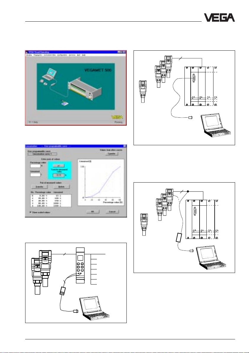
Adjustment with PC
The set-up and adjustment of the ultrasonic
sensors is generally made on the PC with the
adjustment program VVO (VEGA Visual Operating) under Windows®.
The program leads quickly through the adjustment and parameter adjustment via pictures, graphics and process visualizations.
2
2
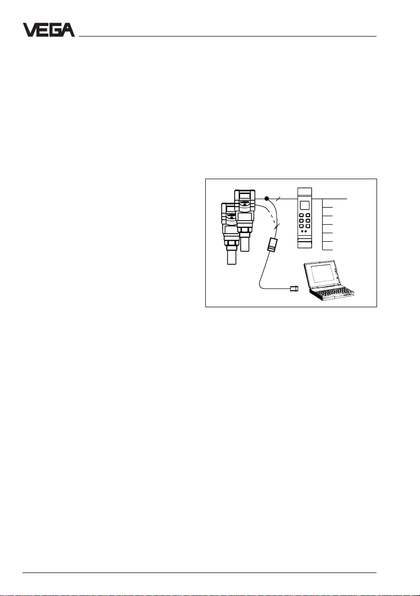
Adjustment with PC on the digital signal and supply
line between the sensors and the signal conditioning
instrument VEGAMET or on the sensor itself (figure:
VEGASON 51 V)
The PC can be connected to any individual
position of the system or the signal line. It is
hence connected with the two-wire PC-interface converter VEGACONNECT 2 to the sensor, the signal line or to the signal conditioning instrument, but also with a standard cable
(RS232) directly to the processing system
VEGALOG.
The adjustment and parameter adjustment
data can be saved with the adjustment software on the PC and protected with passwords. If required the adjustments can be
transferred quickly to other sensors.
6 VEGASON 51 V … 53 V
Page 7
Product description - Adjustment
2
……
The adjustment program recognizes the sensor type
and the place of the connection
Visualized input of a vessel linearization curve
2
1…15
VEGALOG
VEGALOG
571 CPU
571 EA
Adjustment with PC on the processing system
VEGALOG with standard cable RS 232 (on the
processing system up to 15 sensors can be operated
on one two-wire line)
2
……
1 … 15
VEGALOG
VEGALOG
571 CPU
571 EA
2
Adjustment on the digital signal and supply line to the
processing system VEGALOG 571 or directly on the
sensor
Adjustment with PC on signal conditioning instrument
VEGAMET 515 V (two sensors) or 514 V (one sensor)
VEGASON 51 V … 53 V 7
Page 8

Product description - Adjustment
Adjustment with signal conditioning instrument VEGAMET
The ultrasonic sensors with digital output
signal can be operated beside the PC also
with the signal conditioning instrument
VEGAMET.
%
100
+
-
OK
ESC
CONNECT
2
1
on
514 Ex
6-key adjustment field on the instrument front of a
signal conditioning instrument VEGAMET
For adjustment the digital signal conditioning
instruments VEGAMET 514 V and 515 V are
provided with a 6-key adjustment field with
display. Here the parameter adjustment in
clear text can be made.
The adjustment structure corresponds to the
adjustment on the adjustment module
MINICOM.
Adjustment with adjustment module
MINICOM
The adjustment with the small
(3,2 cm x 6,7 cm) 6-key adjustment module
with display can be compared with that of the
signal conditioning instrument. It is possible
to carry out some sensor relevant adjustments directly on the meas. loop which can
naturally also be made with the signal conditioning instrument.
+
ESC
-
Tank 1
m (d)
12.345
Detachable adjustment module MINICOM
The adjustment module can be plugged into
and removed out of the ultrasonic sensor or
the optional external indicating instrument.
ESC
+
-
Tank 1
m (d)
OK
12.345
2
4 … 20 mA
ESC
+
-
Tank 1
m (d)
OK
12.345
4
OK
%
100
+
-
OK
ESC
CONNECT
2
1
on
514 Ex
Adjustment with the detachable adjustment module on
the ultrasonic sensor or on the external indicating
instrument VEGADIS 10.
8 VEGASON 51 V … 53 V
Page 9
Types and versions
2 Types and versions
2.1 Survey
VEGASON series 50 sensors are a newly
developed generation of very compact, small
ultrasonic sensors. With very narrow space
requirements, they are designed for short
meas. distances (0 ... 15 m) and for standard
applications such as storage tanks, gauge
measurement and buffer tanks.
Due to the small housing dimensions and
process connections the compact sensors
monitor very price favourable your levels.
With the integral indication and the many
features of the "big brothers" of VEGASON
series 80, they open the advantages of an
ultrasonic measurement for applications
where the special advantages of a non-contact measurement were not applicable due to
price reasons.
VEGASON 50 ultrasonic sensors dominate
the two-wire technology perfectly. The supply
voltage and the digital output signal are
transmitted via one two-wire line to the connected signal conditioning instrument
VEGAMET or the processing system
VEGALOG.
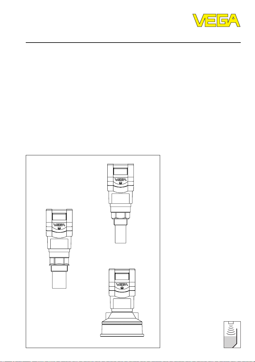
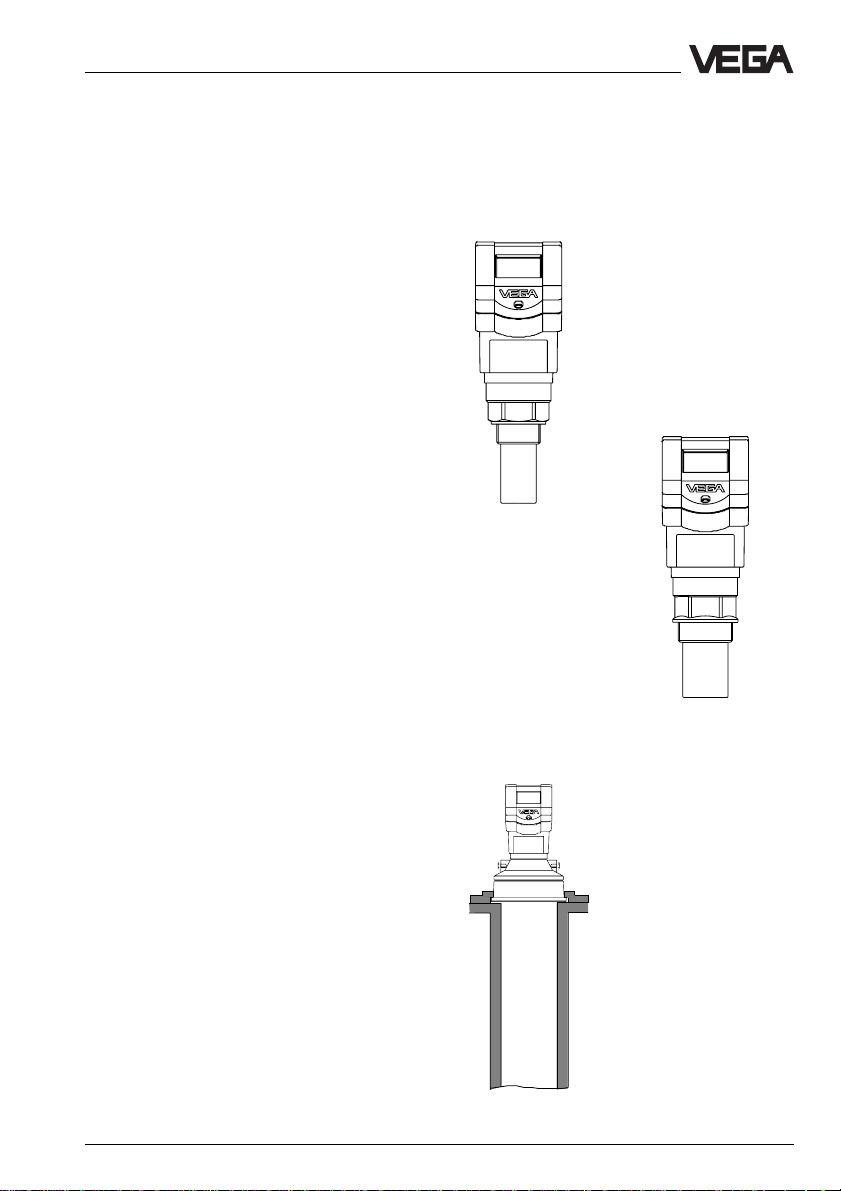
VEGASON 51
with 11/2" thread
VEGASON 52
with 2" thread
VEGASON 53
DN 100 compression flange
(here on a standpipe) or for
mounting with holding strap
VEGASON 51 V … 53 V 9
Page 10
Types and versions - Survey
Survey of the features
• Application in solids
and liquids
• Meas. range 0,25 … 15 m
Signal output
digital meas. signal • • •
Voltage supply
– two-wire technology (voltage
supply and signal output
via one two-wire line) • • –
Process connection
– G11/2 A; 11/2" NPT • – –
– G 2 ; 2" NPT – • –
– DN 100 compression flange – – •
Adjustment
– with PC and adjustment software • • •
– with adjustmet module in sensor • • •
– with adjustmet module in external
indicating instrument • • •
– with signal conditioning
instrument VEGAMET • • •
• Ex-approved in IEC or ATEX
classification EEx ia [ia] IIC T 6
• Integral indication of measured values
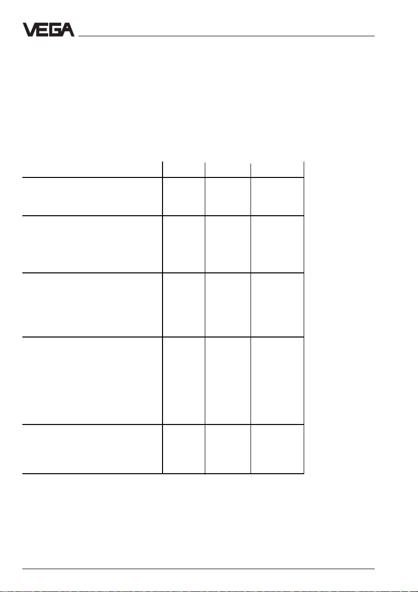
VEGASON …
51 V 52 V 53 V
Meas. range in m
– liquids 0,25 … 4 0,4 … 7 0,6 … 15
– solids 0,3 … 2 0,25…3,5 0,75 … 7
10 VEGASON 51 V … 53 V
Page 11
Types and versions - Survey
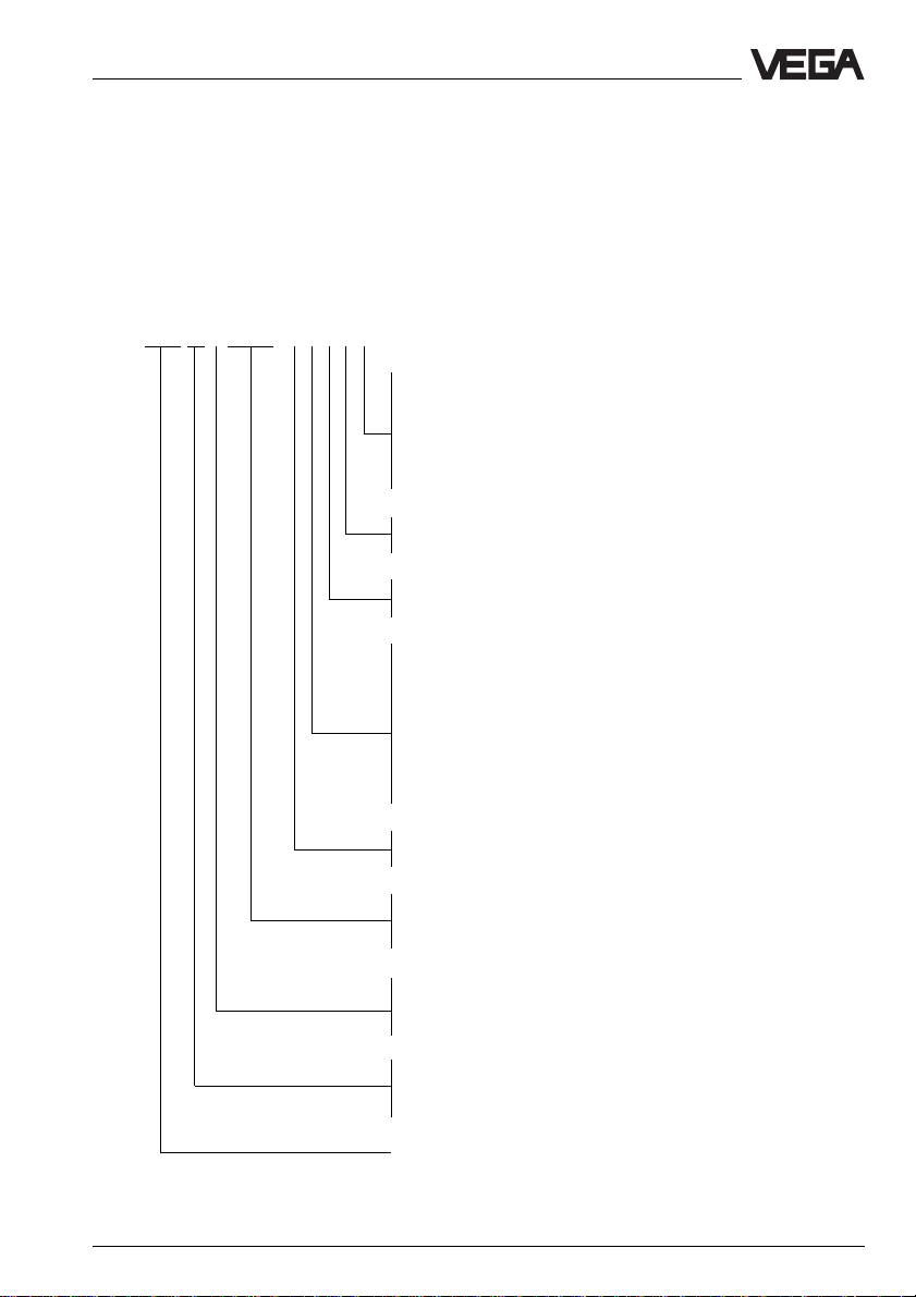
Type code
The second figure of the type designation
e.g. VEGASON 5[1] differentiates the instruments acc. to process connection and meas.
range
VEGASON 51 V E X X . X X X X X (example)
G - Process connection G 11/2 A
N - Process connection 11/2 NPT
X - Process connection DN 100 PN (without compr. flange)
A - Process connection DN 100 PN (PPH compr. flange)
B - Process connection DN 100 PN (1.4571 compr. flange)
C - 1.4301 mounting loop
X - without indication
A - with integral indication
X - without MINICOM adjustment module
B - with MINICOM adjustment module (pluggable)
The figure e.g. VEGASON 51[V] characterizes the output signal:
V stands for a digital output signal.
A - 20 … 72 V DC; 20 … 250 V AC; 4 … 20 mA
B - 20 … 72 V DC; 20 … 250 V AC; 4 … 20 mA; HART
C -Two-wire (loop powered); 4 … 20 mA
D -Two-wire (loop powered); 4 … 20 mA; HART
®
®
E - Supply via signal conditioning instrument
P - 90 … 250 V AC (only in USA)
N - 20 … 36 V DC, 24 V AC (only in USA)
Z - Supply via signal conditioning instrument (only in USA)
U - in USA
X - outside USA
.X - without approval
EX.X - Ex approved CENELEC EEx ia IIC T6
EXS.X - StEx Zone 10
K - Analogue 0 … 20 mA output signal
(two-wire or four-wire technolgoy)
V - Digital output signal (two-wire technology)
Type 51: Meas. range 0,25 … 4 m
Type 52: Meas. range 0,4 … 7 m
Type 53: Meas. range 0,6 … 15 m
Meas. principle (SON for ultrasonics)
VEGASON 51 V … 53 V 11
Page 12

Types and versions - Configuration of measuring systems
2.2 Configuration of measuring systems
A measuring system consists of a sensor
and a processing unit. The processing unit
(signal conditioning instrument VEGAMET or
processing system VEGALOG) processes
the level proportional digital meas. signals
and evaluates these in a number of processing routines.
The levels can then be provided as current,
voltage or switching signals and further processed, e.g. in a weir control.
On the following pages you see the different
instrument configurations called measuring
systems which are shown in the following
partly with a signal processing.
Meas. systems in two-wire technology:
• 2 sensors on one two-wire line
(page 13)
• 2 sensors in Ex on one two-wire line
(page 14)
• 15 sensors on one two-wire line
(page 15)
• 3 sensors in Ex on one two-wire line
(page 16)
Ex
Series 50 sensors require for operation in Exareas the Ex-separator VEGATRENN 548 V
Ex, providing intrinsically safe Ex-circuits.
Note to page 14 and 16:
2)
Sensor lines should be looped in screened cables.
It is suitable to earth the cable screens on both
ends. However it must be noted that no earth
compensation currents flow via the screens.
Earth compensation currents can be avoided with
earthing on both ends by connecting the cable
screen on one earth end (e.g. in the switching
cabinet) via a capacitor (e.g. 1 µF, 100 V) to the
earth potential.
Sensor lines leading to the same separator card,
can be looped together in one screened multiple
wire cable.
Sensor lines leading to other separator cards, must
be looped in separate, screened cables.
12 VEGASON 51 V … 53 V
Page 13
Types and versions - Configuration of measuring systems
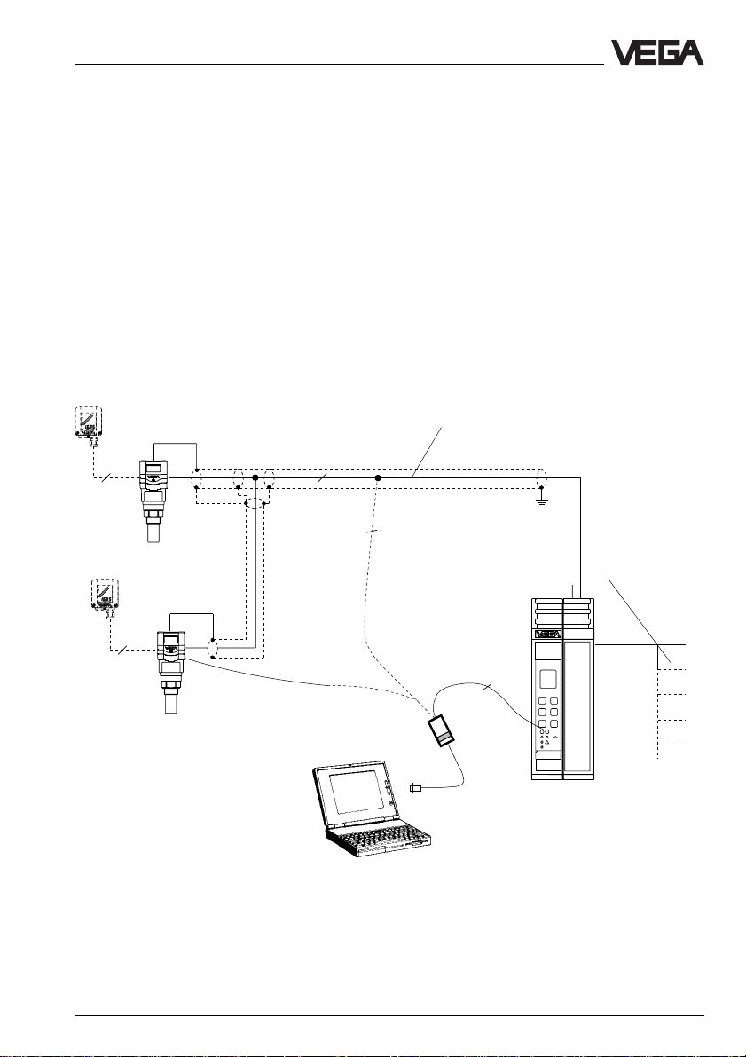
1 … 2 sensors on signal conditioning instrument VEGAMET 515 V
• Two-wire technology, supply from signal conditioning instrument. Output
signals and voltage supply via one two-wire line.
• Digital output signal, two sensors on one line.
• Measured value indication in sensor and in signal conditioning instrument.
• Optionally external indicating instrument.
(can be mounted up to 25 m separated from the sensor in Ex-area).
• Adjustment with PC, signal conditioning instrument or adjustment module
(can be plugged in sensor or in external indicating instrument).
• Max. resistance of the signal line 15 Ω per wire or 1000 m
cable length
VEGADIS 50
Screened line in case of electromagnetic interferences
4
2
2
VEGADIS 50
Current outputs
Voltage outputs
Relays
Digital connection
Fault signals
4
2
VEGACONNECT 2
VEGAMET
515V
Signal conditioning instrument VEGAMET 515 V in
housing type 505
1) Sensor lines should be looped in screened
cables. It is suitable to earth the cable
screens on both ends. However it must be
noted that no earth compensation currents
Processings see also product information
"Signal conditioning instruments series 500"
flow via the screens.
Earth compensation currents can be avoided
with earthing on both ends by connecting the
cable screen on one earth end (e.g. in the
switching cabinet) via a capacitor (e.g. 1 µF,
100 V) to the earth potential.
VEGASON 51 V … 53 V 13
Page 14
Types and versions - Configuration of measuring systems
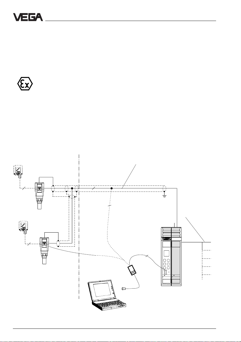
1 … 2 sensors in Ex-area via separator VEGA TRENN 548 V Ex on signal conditioning instrument VEGAMET 515 V
• Two-wire technology, supply from the signal conditioning instrument. Output
signals and voltage supply via one two-wire line (optionally with
VEGASON 53 four-wire technology)
• VEGASON 51 … 52: CENELEC EEx ia IIC T6
VEGASON 53: StEx Zone 10
• Digital output signal, two sensors on one line.
• Measured value indication in the sensor and in the signal conditioning in
strument.
• Optionally external indicating instrument
(can be mounted up to 25 m separated from the sensor in Ex-area).
• Adjustment with PC, the signal conditioning instrument or the adjustment
module (can be plugged into the sensor or the external indicating instru
ment).
• Max. resistance of the signal line 15 Ω per wire or 1000 m cable length note
the permissible values for capacitance and inductance at the connection
cable (see approval certificate of the separators)
VEGADIS 50
4
VEGADIS 50
Ex-area
Not Ex-area
Screened line in case of electromagnetic interferences
2
Current outputs
2
Voltage outputs
Relays
Digital wiring
Fault signals
4
2
VEGACONNECT 2
VEGAMET
VEGATRENN
515V
547
Signal conditioning instrument VEGAMET
515 V with Ex-separator VEGA TRENN
548 V Ex in housing type 506
Processings see also product information
"Signal conditioning instruments series 500"
14 VEGASON 51 V … 53 V
Page 15

Types and versions - Configuration of measuring systems
15 sensors via one two-wire line on the processing system VEGALOG 571
• Two-wire technology, power supply and digital output signals via one twowire line from the processing system VEGALOG 571.
• 15 sensors on one two-wire line.
• Measured value indication integrated in the sensor.
• Optionally external indicating instrument
(can be mounted up to 25 m separated from the sensor in Ex-area).
• Adjustment with PC or adjustment module
(can be plugged into the sensor or external indicating instrument).
• Max. resistance of the signal line 15 Ω per wire or 1000 m cable length.
4
VEGADIS 50
4
4
Screened line in case of electromagnetic
interferences
2
2
2
2
2
2
VEGASON 51 … 53
(15 sensors per two-wire line
can be individually grouped)
1)
2
CPU
VEGALOG
VEGALOG
571 CPU
571 EV
Processing system VEGALOG 571
with input cards in 19"-rack. 15
sensors on one module card and
two-wire line
Processings see also product information
VEGACONNECT 2
Interface cable
RS 232
"Signal conditioning instruments series 500"
1) Sensor lines should be looped in screened
cables. It is suitable to earth the cable
screens on both ends. However it must be
noted that no earth compensation currents
flow via the screens.
Earth compensation currents can be avoided
with earthing on both ends by connecting the
cable screen on one earth end (e.g. in the
switching cabinet) via a capacitor (e.g. 1 µF,
100 V) to the earth potential.
Current outputs
Voltage outputs
Relays
Digital wiring
Fault signals
Connection to all Bussystems
Transistor outputs
VEGASON 51 V … 53 V 15
Page 16
Types and versions - Configuration of measuring systems
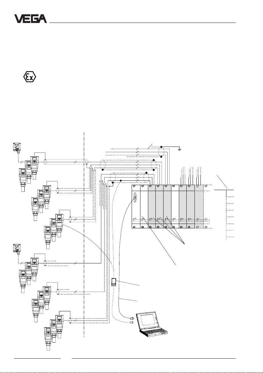
3 sensors per two-wire line via separator VEGA TRENN 548 V Ex on the
processing system VEGALOG 571
• Two-wire technology, power supply and digital output signals via one twowire line from the separator.
• Three sensors on one two-wire line.
• Measured value indication integrated in the sensor.
• Optionally external indicating instrument
(can be mounted up to 25 m separated from the sensor in Ex-area).
• Adjustment with PC or adjustment module
(can be plugged in the sensor or external indicating instrument).
• Max. resistance of the signal line 7,5 Ω per wire or 1000 m cable length,
note the permissible values for capacitance and inductance of the connection cable (see also approval certificates of the separators).
VEGADIS 50
2
Ex-area
Not Ex-area
Screened line in case of electromagnetic
interferences
2
2
2
22
2
2)
(see page 12)
2
2
2
2
2
2
2
2
2
Processing system
CPU
VEGALOG 571
(19" module card)
VEGALOG
VEGALOG
VEGATRENN
571 CPU
VEGATRENN
571 EV
548
VEGACONNECT 2
VEGATRENN
VEGALOG
VEGATRENN
VEGATRENN
571 EV
548
548
548
548
Separator VEGATRENN 548V Ex
(max. 9 sensors per card)
Input card of VEGALOG 571
(max. 15 sensors per card)
Current and
voltage outputs
Digital wiring
Fault signals
Transistor outputs
Connection to all
Bus-systems
Relays
Interface cable RS 232
2
VEGASON 51 … 53
3 sensors per two-wire line, individual
2
grouping
16 VEGASON 51 V … 53 V
Page 17

Technical data
3 Technical data
3.1 Data
Type 51… 52… 53…
Power supply
Supply voltage from signal conditioning instrument VEGAMET or
Current consumption max 22,5 mA
Power consumption max. 80 mW 0,45 VA
Meas. range (relating to the transducer diaphragm)
Liquid 0,25 … 4 m 0,4 … 7 m 0,6 … 15 m
Solid 0,30 … 2 m 0,5 … 3,5 m 0,75 … 7 m
Output signal
Digital meas. signal (VBUS)
Adjustment
- PC with adjustment software software VEGA Visual Operating
- adjustment module MINICOM
processing system VEGALOG 571 (max. 36 V DC)
fuse 0,5 A (slow-blow)
Accuracy (type, values under reference conditions)
1)
Linearity error after adjustment < 0,1 % (relating to max. meas. range)
Average temperature error of sensor
electronics < 0,03 %/10 K of meas. range
Resolution 1 mm
Characteristics
Min. span
(between empty and full adjustment) > 10 mm (recommended > 50 mm)
Ultrasonic frequency 70 kHz 55 kHz 38 kHz
Meas. intervals 1,0 s 1,0 s 0,6 s
Beam angle 5,5° 5,5° 3°
(at -3 dB emitted power)
1) Reference conditions acc. to IEC 770, e.g.:
Temperature: 18 ... 30°C
etc.
VEGASON 51 V … 53 V 17
Page 18

Technical data
Ambient conditions
max. vessel pressure (gauge pressure)
- VEGASON 51 and 52 3 bar
- VEGASON 53 2,5 bar
Ambient temperature
- sensor (electronics) -20°C … +60°C
- process (transducer) -20°C … +80°C (StEx: -20°C … +75°C)
- storage and transport temperature -40°C … +80°C
Protection
- sensor IP 67
- transducer, process IP 68
Protection class II
Overvoltage category III
Ex-technical data (note approval documents)
Classification ia (intrinsically safe in conjunction with a safety
barrier or separator)
Temperature class (permissible ambient
temperature on transducer when used
in Ex-areas)
- T6 45°C
- T5 60°C
- T4 60°C
- T3 60°C
Ex-approved in category or zone
- EC-type approval Zone 1 (II 2 G); Type 53: Zone 21 (II 2 D)
- conformity certificate Zone 1; Type 53: Zone 10
Classification EEx ia IIC T6
Materials
Housing PBT (Valox)
Transducer, process thread PVDF
Compression flange PP or 1.4571
Transducer diaphragm (type 53) 1.4571
Weights (incl. transducer)
- VEGASON 51 1,2 kg
- VEGASON 52 1,6 kg
- VEGASON 53 2,3 kg
18 VEGASON 51 V … 53 V
Page 19

Technical data
Process connections
VEGASON 51 G 11/2 A, 11/2" NPT
VEGASON 52 G 2 A, 2" NPT
VEGASON 53 DN 100 compression flange
Connection lines
Two-wire sensors
- supply and voltage via one two-wire line
line resistance max. 15 Ω per wire or 1000 m cable length
Cross-section area of conductor generally 2,5 mm
Earth connection max. 4 mm
2
2
Cable entry 2 x M20 x 1,5 (cable diameter 5 … 9 mm)
CE-Conformity
VEGASON series 50 ultrasonic sensors meet the protective regulations of EMVG (89/336/
EWG) and NSR (73/23/EWG). The conformity has been judged acc. to the following standards:
EMVG Emission EN 50 081 - 1: 1993
Susceptibility EN 50 082 - 1: 1995
NSR EN 61 010 - 1: 1993
Outputs and processinds
Display indication
Indication optionally integral, scalable analogue and digital
Signal output
Signal output digital output signal in two-wire technology
Two-wire technololy:
The digital output signal (meas. signal) is modulated to the power supply and processed in
the signal conditioning instrument or in the processing system.
VEGASON 51 V … 53 V 19
measured value indication
optionally external measured value indication
powered by the sensor which can be mounted
up to 25 m from sensor
(VBUS)
Page 20

Technical data - Approvals
3.2 Approvals
When using ultrasonic sensors in Ex-areas
the instruments must be suitable and approved for these explosion zones and applications. For the use on ships special type
approval certificates are available.
In hazardous areas (due to gases, vapours,
fog and dusts) only appropriately approved
instruments must be used.
The suitability is checked by the approval
authorities and is certified in approval documents.
VEGASON 51 V Ex and VEGASON 52 V Ex
sensors must be powered for the use in Exzone from one intrinsically safe circuit. This is
ensured by the separator VEGATRENN
548 V Ex.
The separator provides intrinsically (ia) circuits. The resistance of the signal line must
not exceed 15 Ω per wire.
VEGASON 51 V Ex and VEGASON 52 V Ex
sensors are approved for Ex-zone 1.
VEGASON 53 V ExS is approved for Exzone 10 or zone 21.
As proof for the Ex-approval appropriate
confirmity certificates and type approval
certificates of the approval authorities are
attached to the sensors.
Test and approval authorities
VEGASON ultrasonic sensors are tested and
approved by the following monitoring, test
and approval authorities:
- PTB
(Physikalisch Technische Bundesanstalt Physical Technical Approval Authority)
- FM
(Factory Mutual Research)
- ABS
(American Bureau of Shipping)
- LRS
(Lloyds Register of Shipping)
- GL
(German Lloyd)
- CSA
(Canadian Standards Association)
Please note the attached approval documents when you want to use a sensor in Exareas.
20 VEGASON 51 V … 53 V
Page 21
Technical data - Dimensions
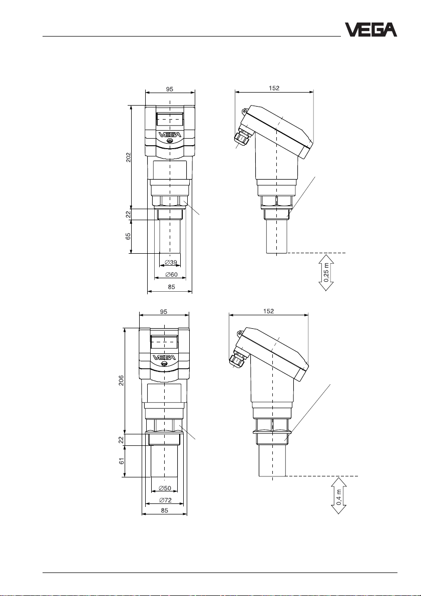
3.3 Dimensions
VEGASON 51
VEGASON 52
2 x M20x1,5
Thread G 11/2 A or 11/2" NPT
Reference pane
Min.-distance
to the product
Thread G 2 A or 2" NPT
SW 60
Reference pane
Min.-distance
to the product
VEGASON 51 V … 53 V 21
Page 22
Technical data - Dimensions
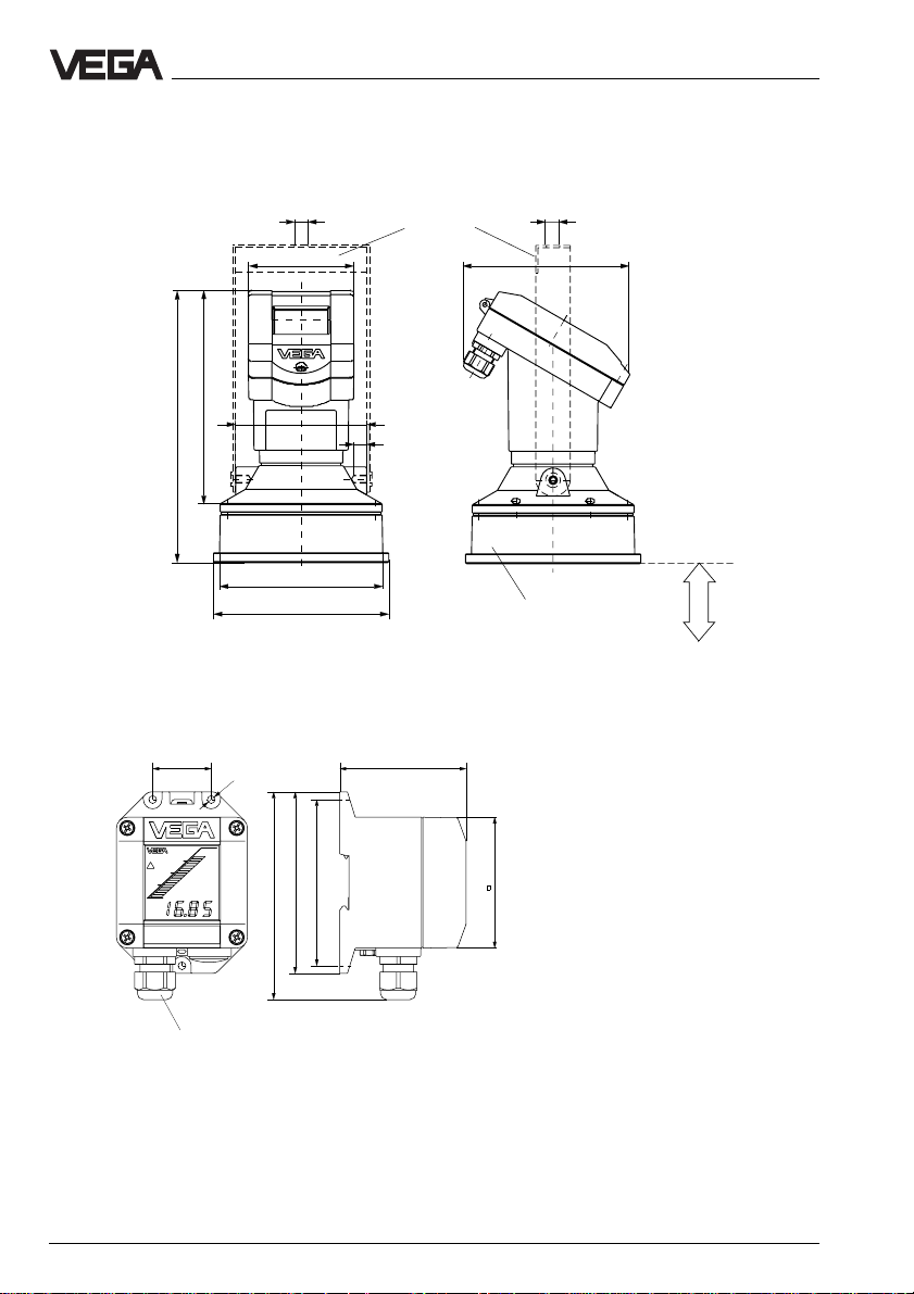
VEGASON 53
ø12
Mounting loop
95
247
193
120
12
M8x10
ø148
ø158
External indicating instrument VEGADIS 50
38
ø5
82
ø12
152
suitable for compression
flange DN 100
Min.-distance
to the product
0,6 m
118
108
135
Pg 13,5
M20 x 1,5
Mounting on carrier rail 35 x 7,5 acc. to EN 50 022 or flat
screwed
85
Note:
The cable diameter of the connection cable
must be 5 … 9 mm.
The seal effect of the cable entry is otherwise
not ensured.
22 VEGASON 51 V … 53 V
Page 23
Mounting and installation - General installation instructions
4 Mounting and installation
4.1 General installation instructions
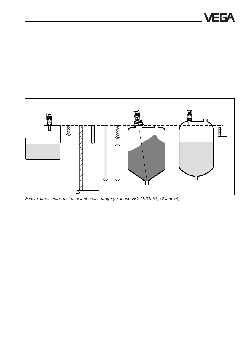
Measuring range
You select your instrument beside other criteria according to the required measuring
range. The reference panes for the min. and
max. distance to the product or the solid is
either the transducer surface (diaphragm) or
on instruments with flange version the instru-
ment flange. Note the information for the reference panes in chapter "Dimensions". The
max. filling is dependent on the required min.
distance of the instrument used (0,25 m to
0,75 m) and the installation place of the instrument or the transducer.
Type 51
Min.
distance
0,25 m 0,4 m
4 m
(type 51)
full
1m
15 m (type 53)
empty
Min.
distance
0,75 m
Type 53 Type 52
Reference pane
Meas. range
Min. distance, max. distance and meas. range (example VEGASON 51, 52 and 53)
Min.
distance
7 m (type 52)
VEGASON 51 V … 53 V 23
Page 24
Mounting and installation - General installation instructions
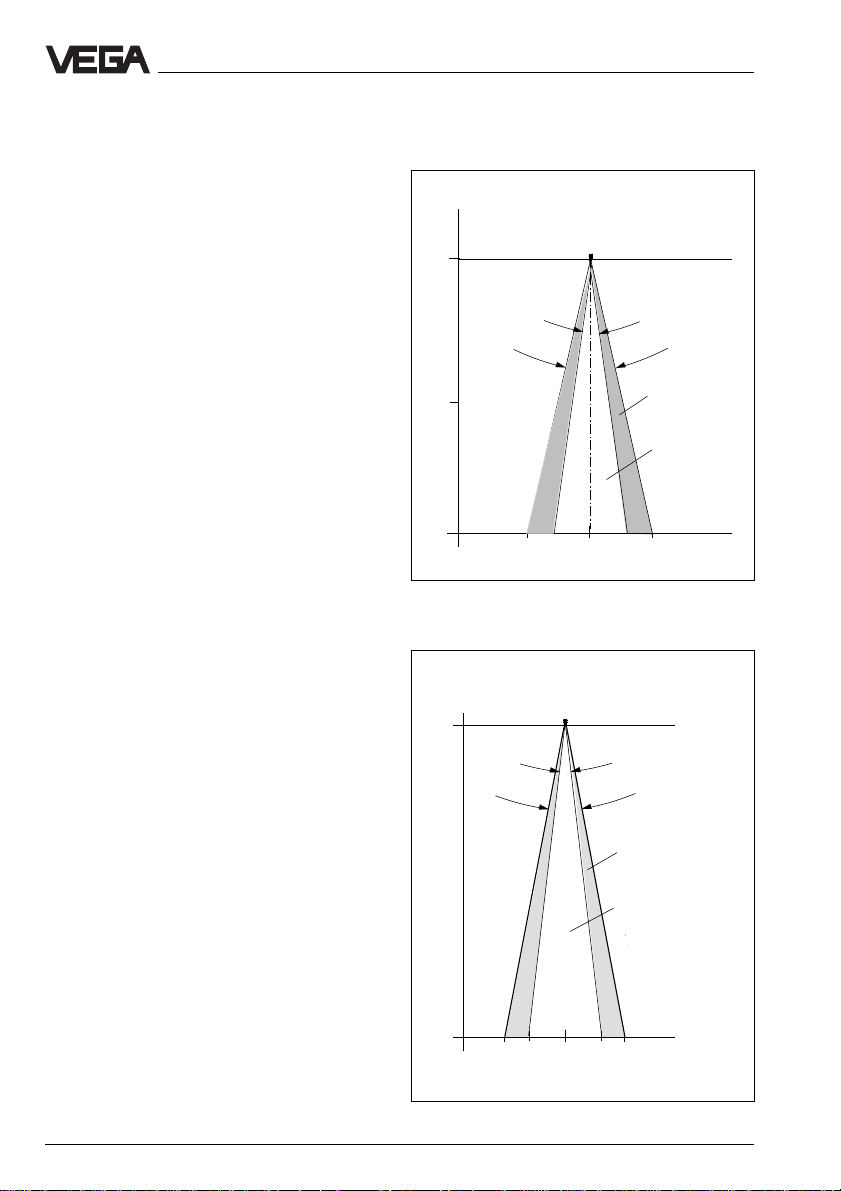
Beam angle and false echoes
The ultrasonic impulses are focussed by the
transducer. The impulses leave the transducer in conical form similar to the beam
pattern of a spotlight. The beam angle is 5,5°
(type 51/52) or 3° (type 53) at -3 dB emitted
power.
Any object in this beam angle causes a false
echo. Within the first few metres of the beam
angle, tubes, struts or other installations
cause strong false echoes. In a distance of
2 m the false echo of a strut has 9-times more
amplitude than at a distance of 6 m.
If possible, provide a vertical directing of the
sensor axis to the product surface and avoid
if possible, struts within the 100%-beam
angle, e.g. by tubes and struts.
Meas. distance
0 m
4 m
7 m
Meas. distance
0 m
VEGASON 51/52
0,4
0
VEGASON 53
0,4
5,5°
12°
50 %
Emitted power
100 %
Emitted power
1,21,2
m
3°
8°
50 %
Emitted power
Emitted power
100 %
15 m
0,4
1,2
0,4
0
m
1,2
24 VEGASON 51 V … 53 V
Page 25
Mounting and installation - Measurement of liquids
4.2 Measurement of liquids
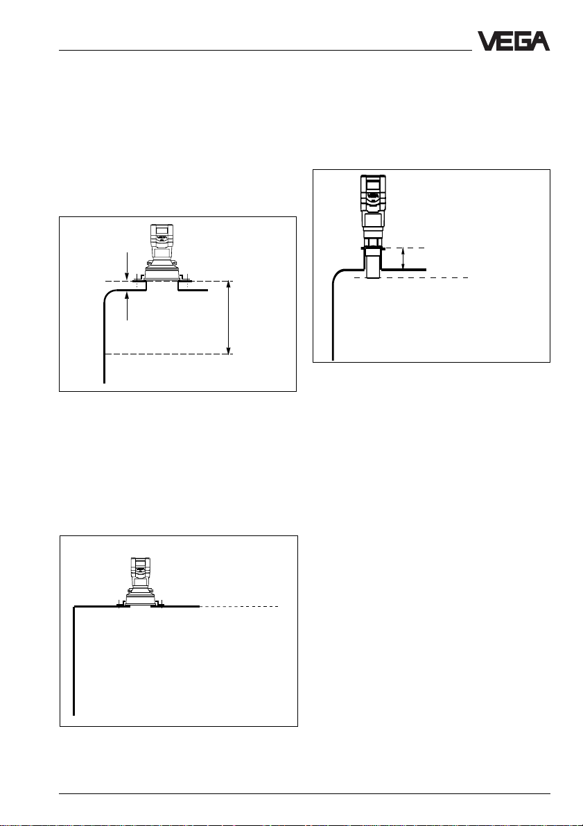
Flat vessel tops
On flat vessels the mounting is mainly made
on a very short DIN-socket piece. Reference
pane on flange versions is the instrument
flange. The transducer should protrude out of
the flange pipe.
Reference pane
You can also mount the sensors with 11/2" or
2" thread to short socket pieces.
< 60 mm
Reference pane
< 60 mm
Flange version on very short DIN-socket piece
Min.
distance
Very suitable is the mounting directly on the
vessel top. A round opening on the vessel is
sufficient to fasten VEGASON 53 sensor with
a compression flange.
Reference pane
Mounting on short 11/2" or 2" socket piece
Flange version (compression flange) on flat vessel
top
VEGASON 51 V … 53 V 25
Page 26
Mounting and installation - Measurement of liquids
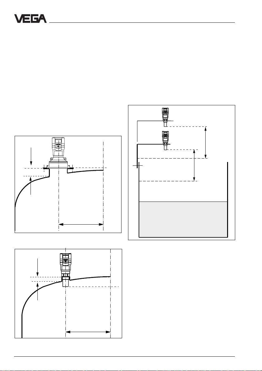
Dished tank ends
On dished tank ends please do not mount
the instrument in the centre but approx. 1/2
vessel radius from the centre. Dished tank
ends can act for the ultrasonic pulses as
paraboloidal refelctors. If the transducer is
placed in the "focus" of the parabolic tank
end, the transducer receives amplified false
echoes. Hence the transducer should be
mounted outside the "focus". Parabolic amplified false echoes are hence avoided.
Reference pane
< 60 mm
1
/2 vessel radius
Open vessels
On open vessels the use of the instruments
on a mounting lever is recommended. Mount
the low-weight sensor to a mounting lever.
Reference pane
Min. meas.
distance
Min. meas.
distance
Flange on dished vessel ends
Open vessels
< 60 mm
Reference pane
1
/2 vessel radius
Mounting boss on a dished tank end
26 VEGASON 51 V … 53 V
Page 27
,,
Mounting and installation - Measurement of liquids
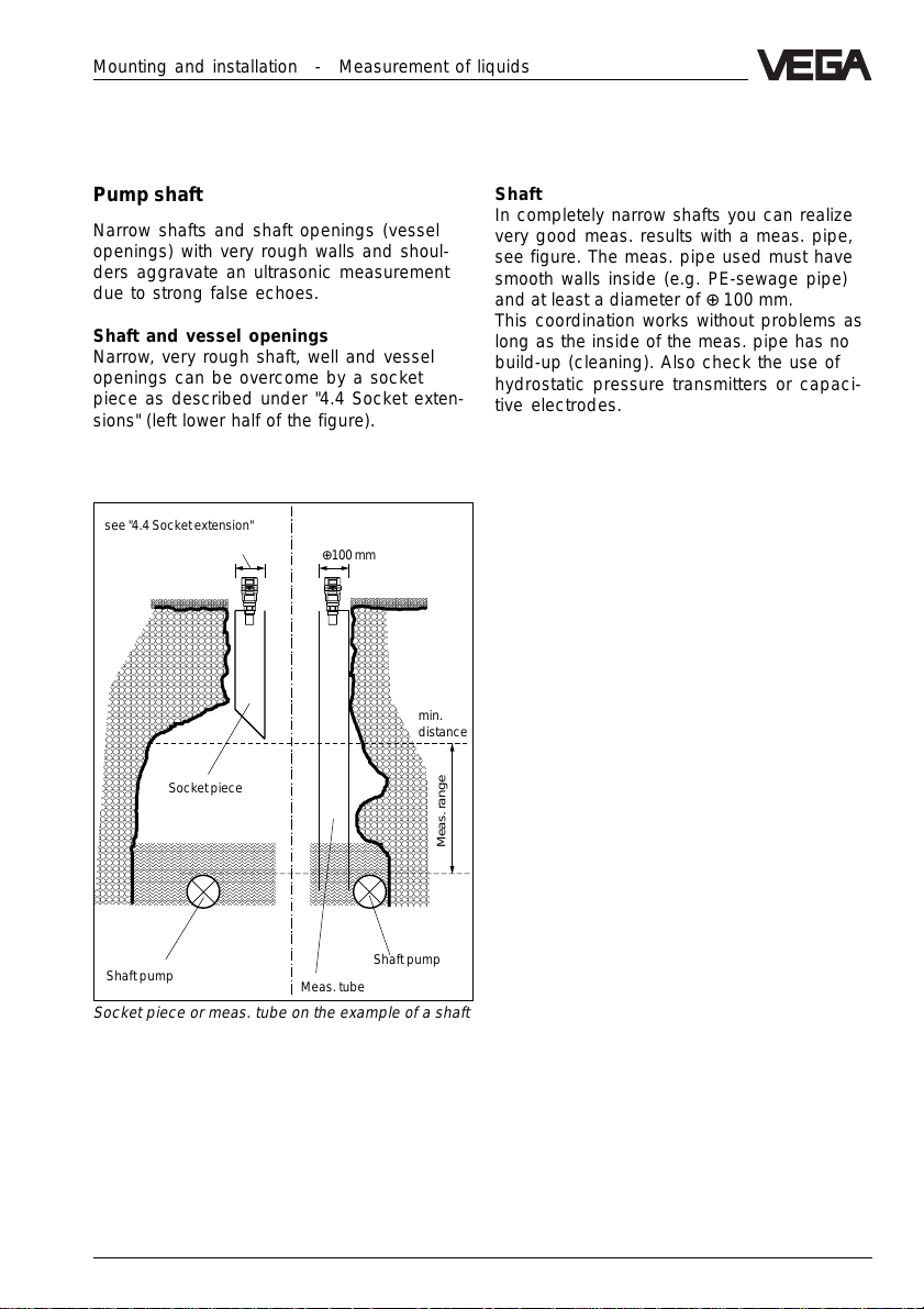
Pump shaft
Narrow shafts and shaft openings (vessel
openings) with very rough walls and shoulders aggravate an ultrasonic measurement
due to strong false echoes.
Shaft and vessel openings
Narrow, very rough shaft, well and vessel
openings can be overcome by a socket
piece as described under "4.4 Socket extensions" (left lower half of the figure).
see "4.4 Socket extension"
⊕100 mm
,,,,,,,,,,,
min.
distance
Socket piece
Shaft
In completely narrow shafts you can realize
very good meas. results with a meas. pipe,
see figure. The meas. pipe used must have
smooth walls inside (e.g. PE-sewage pipe)
and at least a diameter of ⊕ 100 mm.
This coordination works without problems as
long as the inside of the meas. pipe has no
build-up (cleaning). Also check the use of
hydrostatic pressure transmitters or capacitive electrodes.
Meas. range
Shaft pump
Meas. tube
Shaft pump
Socket piece or meas. tube on the example of a shaft
VEGASON 51 V … 53 V 27
Page 28

Mounting and installation - Measurement of solids
4.3 Measurement of solids
Flange mounting
As with liquids, also in solid vessels the instrument can be mounted on a short DINsocket piece. The socket axis must point to
the vessel outlet or should be directed vertically to the product surface and must be
very short (< 100 mm).
Reference pane
Min. distance
Swivelling holder
The accessory program offers a swivelling
holder (mounting loop) for mounting of
VEGASON 53. This facilitates the directing of
the sensor to the product surface.
Reference pane
Min. distance
VEGASON 53 on vessel flange
28 VEGASON 51 V … 53 V
VEGASON 53 on swivelling holder
Page 29

,,,,,,,,,,,,,,,,,,,,,,,,,,,,,,,,,,,,
Mounting and installation - Measurement of solids
Mounting boss
Reference pane
Min. distance
VEGASON 51 or 52 on the mounting boss. The socket
axis should point to the product surface
Material cones
Large material cones are detected with several instruments which you can fasten on
lifting beams.
T ransducer on lifting beam above material cone
VEGASON 52 on mounting boss
VEGASON 51 V … 53 V 29
Page 30

,
,
,
,
,
,
,
,
,
4.4 Socket extensions
The ultrasonic sensor requires a min. distance to the product or solid. Note this min.
distance in your planning.
In exceptions it is possible to reach the required min. distance and hence the desired
filling height with a socket piece. However
the socket piece increases the noise level of
the ultrasonic signal and can interfere the
measurement. Only provide the socket extension when there is no other possibility and
carry out the extension as shown in the following figure.
Socket extensions with liquids
Chamfer the socket carefully and ensure a
smooth inner side of the socket. The socket
should not protrude into the measured product when pollution or measured product
could stick to the socket.
Mounting and installation - Socket extensions
Type 51/52
L
Socket extension with liquids
Type 53
L
45˚45˚
Max. socket length dependent on the socket
diameter
ø L in mm
in mm Type 51 Type 52 Type 53
100 200 300 300
150 300 400 400
200 – 500 500
250 – – 600
,,,,,,,,,,,,,,,
,,,,,,,,,,,,,,,,
,,,,,,,,,,,,,,,,
,,,,,,,,,,,,,,,
,,,,,,,,,,,,,,,
,,,,,,,,,,,,,,,
,,,,,,,,,,,,,,,
,,,,,,,,,,,,,,,
,,,,,,,,,,,,,,,
Socket extension with solids
For solids provide a conical socket extension
with an angle of at least 15° … 20°.
Socket piece should not penetrate into adhesive
products (VEGASON 53)
Choose a possibly large socket diameter
and a possibly small socket length, ensure
that the socket opening is burr free to minimize false echoes.
15°
15°
For measurements in products which do not
cause any build-up, the socket extension in
form of a meas. pipe can be submerged
permanently into the measured product. The
Socket extension with solids
ultrasonic measurement is then only carried
out in the meas. pipe without being interfered
by vessel installations (see page 28 "Pump
shaft").
30 VEGASON 51 V … 53 V
Page 31

Mounting and installation - Flow measurement
4.5 Flow measurement
The short examples on this page should give
just introductory information for your flow
measurement. Planning information is given
by the flume manufacturers and in special
literature.
Rectangular flume
- Installation of the sensor on the upstream
side
- Note distance to the overfall edge
(3…4xh
- Installation centered to the flume
- Edge opening ⊕ 2xh
- Installation perpendicular to the liquid
surface
- Keep min. distance relating to h
- Min. distance of the edge opening of
downstream water ⊕ 50 mm
max
)
from ground
max
max
Khafagi-Venturi flume
- Installation of the sensor on the inlet side
- Note distance to the Khafagi-Venturi flume
(3…4xh
- Installation perpendicular to the liquid
surface
- Keep min. distance relating to the height of
damming h
max
max
3 … 4 x h
90°
)
max
h
max
90°
Overfall edge
< min. distance
h
max
⊕ 2 x h
max
Khafagi-Venturi flume
Sensor
B
Flow measurement on open flumes
Overfall edge
3 … 4 x h
max
90°
⊕ 5 cm
Upstream water
Downstream water
Flow measurement on open flumes
VEGASON 51 V … 53 V 31
Page 32

4.6 False echoes
The installation place of the ultrasonic sensor
must be selected such that no installations or
inflowing material cross the ultrasonic impulses. The following examples and instructions show frequent meas. problems and
how they can be avoided.
Shoulders
Vessel forms with flat shoulder can aggravate
the measurement due to the strong false
echoes. Shields above these flat shoulders
spread the false echoes and ensure reliable
measurement.
Correct Wrong
Shoulders
Inlets, e.g. for material mixing with flat upper
side pointing to the sensor, should be covered by an angle shield. The false echo is
hence gated out.
Correct Wrong
Mounting and installation - False echoes
Vessel installations
Vessel installations such as e.g. a ladder
often cause false echoes. Note when planning your measurement loop that the ultrasonic signals should reach the product without problems.
Correct Wrong
Ladder
Vessel installations
Ladder
Struts
Struts such as vessel installations can cause
strong false echoes which can overlay the
useful echo. Small shields avoid a direct false
echo reflection. The false echoes are diffused
and filtered out by the meas. electronics as
"echo noise".
Correct Wrong
Shields
Shoulder (inlet)
32 VEGASON 51 V … 53 V
Struts
Page 33

,,
,,
,
Mounting and installation - False echoes
,
Flood basin
The max. high water to be expected determines the installation height to keep the min.
distance of the transducer even with highest
high water.
The low water edge should be covered in the
transducer range with a shield.
Correct Wrong
Min. distance
high water
60°
Shield
,,,,,
Low water
,,,,,,
Gating out of an echo
Inflowing material
Do not mount the instrument in or above the
filling stream. Ensure that you detect the
product surface and note the inflowing material.
Correct
Wrong
Inflowing liquid
Build-up
If the sensor is mounted too close to the
vessel wall, build-up on the vessel walls
causes false echoes. Position the sensor in a
sufficient distance to the vessel wall. Also
note chapter "4.1 General installation instructions".
Correct
Wrong
Correct
Wrong
Build-up
Inflowing liquid
VEGASON 51 V … 53 V 33
Page 34

Strong product movements
Heavy turbulences in the vessel, e.g. by
strong stirrers or strong chemical reactions,
aggravate the measurement. A surge or
bypass pipe (figure) of sufficient size allows,
provided that the product causes no buildup in the pipe, always a reliable measurement even with strong turbulences in the
vessel.
Mounting and installation - False echoes
Strong product movements
34 VEGASON 51 V … 53 V
Page 35

,
,
,
,
Mounting and installation - Installation error
4.7 Installation error
Foam generation
Strong foam on the product can cause faulty
measurements. Provide measures to avoid
foam, measure in a bypass pipe or use another meas. principle, e.g. capacitive electrodes of hydrostatic pressure transmitters.
,,,,,,,,,,,,,
,,,,,,,,,,,,,
,,,,,,,,,,,,,
,,,,,,,,,,,,,
Strong heat fluctuations
Strong heat fluctuations, e.g. due to the sun,
cause meas. errors. Provide a shield.
Shield
Foam generation
Wrong directing to the product
If the sensor is not directed to the product
surface, weak measuring signals are caused.
Direct the sensor axis vertically to the product surface to reach optimum meas. results.
Direct sensor vertically to the product surface
Strong heat fluctuations
Min. distance to the product
When the min. distance to the product is not
maintained, the instruments show wrong
measured values (see page 23). Mount the
instruments with the required min. distance.
VEGASON 51 V … 53 V 35
Page 36

Mounting and installation - Installation error
Sensor too close to the vessel wall
Correct Wrong
Sensor too close to the vessel wall
If the sensor is mounted too close to the
vessel wall (dimension A in diagram) strong
false echoes can be caused. Build-up, rivets,
screws and weld joints superimpose their
echoes to the product echo or useful echo.
Hence note a sufficient distance of the sensor
to the vessel wall dependent on the max.
meas. distance (dimension B in diagram). In
case of good reflection conditions (liquids, no
vessel installation) we recommend to provide
the sensor distance according to diagram
curve 1. At a max. meas. distance of e.g.
10 m the distance of the transducer according to curve 1 would be approx. 1 m.
In case of solids with bad reflection conditions provide a distance to the vessel wall
according to diagram curve 2. With very
bad meas. conditions it can be necessary to
increase the distance to the vessel wall or to
gate out the false echoes additionally by a
false echo storage and hence to adapt the
sensor more precisely to the environment.
Distance of the
transducer to the
vessel wall
A
1 m 2 m 3 m 4 m 5 m
Curve 1 (liquids)
5 m
B
Max. meas.
distance
10 m
15 m
Curve 2 (solids)
36 VEGASON 51 V … 53 V
Page 37

Mounting and installation - Installation error
Socket piece too long
When mounting the sensor in a too long
socket piece, strong false echoes are
caused, aggravating the measurement. Note
that the transducer protrudes at least 30 mm
out of the socket piece.
Wrong
Correct
< 60 mm
Reference pane
Correct and wrong length of socket piece
Parabolic effects on dished boiler head
or basket arch vessels
Round or paraboilic tank tops act for the
signals like a paraboilic mirror. If the sensor is
placed to the focus of such a paraboilic tank
top the sensor receives amplified false echoes. The optimum mounting is generally in the
range of the half vessel radius from the centre.
Correct
< 60 mm
~ 1/
2
vessel
radius
Wrong
Wrong
Mounting on a vessel with parabolic tank top
VEGASON 51 V … 53 V 37
Page 38

5 Electrical connection
5.1 Connection and connection cable
Safety information
Ensure that the instrument is unpressurized
before you start work. Always switch off the
power supply before you carry out clamping
work on the ultrasonic sensors. Protect yourself and the instruments.
Electrical connection
Ex-protection
If an instrument is used in hazardous areas
the appropriate regulations, conformity certificates and type approvals of the sensors and
separators or safety barriers must be noted
(e.g. DIN VDE 0165).
Skilled staff
Instruments which are operated in Ex-areas
must only be connected by skilled staff. The
skilled staff must know the installation conditions and note the attached type approval
and conformity certificates.
Connection
A standard two-wire cable with max. 2,5 mm
can be used for connection. Very often the
"electromagnetic pollution" by electronic actuators, energy lines and transmitting stations
is so considerable that the two-wire line
should be screened.
We recommend to use a screening. This
screening prevents against future interferences. It is suitable to earth the cable
screens on both ends. However it must be
noted that no earth compensation currents
flow via the screens.
Earth compensation currents can be avoided
with earthing on both ends by connecting the
cable screen on one earth end (e.g. in the
switching cabinet) via a capacitor (e.g. 1 µF,
100 V) to the earth potential. Use a very low
impedance earth connection (foundation,
plate or mains earth).
Sensors which are used in Ex-areas must
only be operated on intrinsically safe circuits.
The permissible electrical values are stated in
the conformity certificate or the type approval.
Connection cable
Note that the connection cable must be speci-
2
fied for the expected operating temperatures
in your systems. The cable must have an outer
diameter of 5 … 9 mm otherwise the seal effect
of the cable entry will not be ensured.
Cables for intrinsically safe circuits must be
marked blue and must not be used for other
circuits.
Earth conductor terminal
On VEGASON 51/52 sensors the earth conductor terminal is galvanically isolated. On
VEGASON 53 sensor the earth conductor
terminal is galvanically connected to the metal
transducer diaphragm.
Note:
In Ex-applications the cable screen of the
connection cable must only be earthed at one
end.
38 VEGASON 51 V … 53 V
Page 39

Electrical connection - Connection of the sensor
5.2 Connection of the sensor
After having mounted the sensor in the meas.
position according to the instructions in chapter "4 Mounting and installation", loosen the
closing screw on the top of the sensor. The
sensor cover with the optional indication
display can then be opened. Unscrew the
compression screw and shift the screw over
the approx. 10 cm dismantled connection
cable. The compression screw of the cable
entry is protected with a safety lock-in position against automatic loosening.
Supply voltage and digital
meas. signal
+
-
Now loop the cable through the cable entry
into the sensor. Screw the compression
screw to the cable entry and clamp the dismantled wires of the cable to the appropriate
terminal positions.
The terminals operate without terminal screw.
Press the white opening buckets with a small
screwdriver and insert the copper core of the
connection line into the terminal opening.
Check the position of the lines in the terminal
position by slightly pulling on the connection
lines.
T o the indicating instrument in the
sensor cover or to the external indicating instrument VEGADIS 50
Earth terminal
The earth terminal must be
connected to system earth
Spring-loaded terminal
12 C 567843
12 C 5678
Commu-
+-
Tank 1
m (d)
12.345
nication
-
+
4...20 mA
Two-wire technology
Display
ESC
OK
Terminals (max. 2,5 mm
wire cross-section)
Sockets for connection of the
interface adapter
VEGACONNECT
Pluggable
adjustment
module
MINICOM
2
VEGASON 51 V … 53 V 39
Page 40

Electrical connection - Connection of the indicating instrument
5.3 Connection of an external indicating instrument VEGADIS 50
Loosen the 4 screws of the housing cover on
VEGADIS 50.
You can facilitate the connection procedure
by fastening the housing cover during connection with two screws on the right of the
housing (figure).
Terminal strip VEGADIS 50
3
2
1
4
5
to DISPLAY in cover of
VEGADIS 50
8
6
7
Adjustment module
-
Tank 1
m (d)
12.345
321 5678
-
+
OUTPUT
+
DISPLAY
VEGADIS 50
ESC
OK
16.85
Voltage supply
and
digital meas. signal
+
-
12 C 567843
-
+
Tank 1
m (d)
12.345
Sensor terminal box
(open)
+
ESC
-
OK
Screws
40 VEGASON 51 V … 53 V
Page 41

Set-up - Adjustment structure
6 Set-up
6.1 Adjustment structure
Series 50 ultrasonic sensors can be adjusted
with
- PC (adjustment program VVO)
- detachable adjustment module MINICOM
- signal conditioning instrument VEGAMET.
Signal conditioning instrument VEGAMET
The signal conditioning instrument VEGAMET
allows with the 6-key adjustment field with
text display the parameter adjustment in the
same functional spectrum than the adjustment program VVO on the PC.
The adjustment must only be carried out with
one adjustment medium.
Adjustment program VVO
With the adjustment program VVO (VEGA
Visual Operating) on the PC you adjust the
ultrasonic sensors very comfortably. The PC
communicates via the interface adapter
VEGACONNECT 2 or the standard RS232
interface cable digitally with the sensor. The
adjustment can be carried out hence directly
on the sensor, at any position of the signal
line or on the processing system VEGAMET/
VEGALOG.
Note:
The adjustment with the PC via the interface
adapter VEGACONNECT 2 directly on the
sensor or on the signal line only allows the
"
Parameter adjustment
the adjustment with the PC on VEGAMET or
VEGALOG on the following pages. Adjustments for "
direct connection of VEGACONNECT 2 to the
sensor or the signal line. Therefore this is
described separately in this operating instruction.
Configuration
" and corresponds to
" are not possible with
Adjustment module MINICOM
With the adjustment module MINICOM you
adjust in the sensor or in the external indicating instrument VEGADIS 50. The adjustment
module ensures with the 6-key adjustment
field with text display the parameter adjustment in the same functional spectrum like the
adjustment program VVO or the 6-key adjustment field with text display on the signal
conditioning instrument VEGAMET.
The configuration adjustments however are
only possible with the adjustment program
VVO or the 6-key adjustment field with text
display on the signal conditioning instrument
VEGAMET.
Independent whether you carry out the setup of a meas. system (consisting of sensor
and signal conditioning instrument VEGAMET
or sensor and processing system
VEGALOG) with the adjustment software
VVO, with the signal conditioning instrument
or with the adjustment module MINICOM, the
way is always the same:
- Configure first a meas. system in the menu
"
Configuration
- carry out the parameter adjustment of the
sensors in the menu "
" and
Instrument data
".
VEGASON 51 V … 53 V 41
Page 42

Configuration means to coordinate or deter mine once. In the menu Configuration the
signal conditioning instrument is informed
about the general configuration:
- which kind of sensor is connected (radar,
ultrasonic, process pressure…),
- what kind of parameter or application is
concerned (level, gauge, distance…)
- to which input the sensor is connected
- which outputs (current, voltage, relay, fault
signals, indication…) should be coordinated to which input in which way (inverted, threshold value controlled…).
After these adjustments (configuration) had
been carried out, the meas. system goes to
operating condition and the signal conditioning instrument will display a measured value.
Now the sensor parameter adjustment (adjustment, unit, linearisation curve, sensor
adaption…) can be carried out.
Parameter adjustment means to enter values.
Parameters are entered in the signal conditioning instrument as well as in the connected
sensors. For example:
- Min. and max. adjustment
- Meas. range limits
- Physical unit, decimal point
- Linearisation curves
- Integration time
- Meas. environment (solid, liquid,
foam generation, operating range…)
- False echo memory
- Inversion of the measured value etc.
Now all required adjustments for a precisely
adapted sensor are carried out for a reliable
measurement.
Set-up - Adjustment with PC on VEGAMET
6.2 Adjustment with PC on VEGAMET
The PC with the adjustment program VVO
(VEGA Visual Operating) can be connected:
- to the sensor
- to the signal line
- to the signal conditioning instrument
VEGAMET 514V/515V
- to the processing system VEGALOG 571
For connection of a PC to a signal conditioning instrument you require the interface
adapter VEGACONNECT 2. The PC communicates via the interface adapter
VEGACONNECT 2 with the signal conditioning instrument and the sensor.
Hence a digital adjustment signal is superimposed to the signal and supply line between
sensor and signal conditioning instrument. In
chapter "2.2 Configuration of measuring systems" the connection of the PC in different
coordinations is shown.
Before starting the set-up:
Take some time to carry out the set-up stepby-step with the PC and soon you will no
more require the following pages.
In any case you are requested to enter or
enquire something, this is marked in the
following with a dot, such as e.g.:
• Choose …
• Start …
• Click to …
Now start to
• connect the standard plug of
VEGACONNECT 2 (9-pole) with the interface COM 1 or COM 2 of your PC.
42 VEGASON 51 V … 53 V
Page 43

Set-up - Adjustment with PC on VEGAMET
• Plug the two small pin plugs of
VEGACONNECT 2 into the CONNECTsocket of the signal conditioning instrument.
• Now switch on the voltage supply of the
signal conditioning instrument.
After approx. 1…2 minutes (selfcheck) the
meas. system is generally ready for operation and indicates measured values.
• Now start the adjustment software VVO on
your PC.
• Choose in the entrance screen with the
arrow keys or the mouse the item "
ning
" and click to "OK".
In the next window you are asked for the
user identification.
Plan-
The adjustment program, just called VVO,
gets in contact with connected coordination/
sensor...... and indicates after a few seconds
if and with which coordination/sensor a connection exists.
The preadjusted identification can be modified later in the menu "User access".
Note:
If you do not get a sensor connection, please
check:
- is the sensor fed with power supply (min.
20 V)?
- do you use an older VEGACONNECT
instead of the new VEGACONNECT 2 ?
If VVO (adjustment software) gets in contact
with the signal conditioning instrument for the
first time, you are asked if the data should be
transferred from the signal conditioning instrument to the PC.
• Click to "
In the following menu window "
choice
• Enter under the name "
• Also enter under the password
VEGASON 51 V … 53 V 43
VEGA
".
"
VEGA
".
or keep the suggested file name.
Yes
"
DISBUS-group
" you can give a name to the database
Page 44

Set-up - Adjustment with PC on VEGAMET
Configuration
Create new measurement loop
• Click to "OK", and you are in the main menu
window.
Before starting the configuration:
The signal conditioning instruments are
preconfigured dependent on the sensor type
you have ordered with the signal conditioning
instrument.
Generally you will use a preconfigured signal
conditioning instrument.
Hence you normally do not have to make any
adjustments in the menu "
ning on this page and in this case you can
directly choose the menu "Parameter adjustment" (on page 46).
Configuration
" begin-
• Choose the menu "
ment loop/Create new
menu window
loop - Application"
• Choose the parameter "
ment
" (gauge or distance) and the sensor
type ("
pulse echo
• Click to "
Continue
Configuration/Measure-
" and you are in the
"Create new measurement
Level measure-
" for ultrasonic).
"
Nevertheless the most important steps in the
menu "
Configuration
exception your signal conditioning instruments
are not preconfigured, then start with the
subchapter "
continue with the adjustments in the subchapter
"
Parameter adjustment
44 VEGASON 51 V … 53 V
" will be shown. If as an
Configuration
" on this page and
" on page 46.
• Choose "Standard level measurement" and
"
no options
• Click to "
"New application - select meas. loop"
opens.
"
Continue
", and the menu window
Page 45

Set-up - Adjustment with PC on VEGAMET
• Choose one of the two inputs of the signal
conditioning instrument VEGAMET
(VEGAMET 514 V has just one sensor
input) and click to "OK"
After a few seconds the menu window "Create new measurement loop - Sensor configuration" opens.
• Confirm with "OK".
• Click in the menu window "Sensor coordination" again to "OK".
You are again in the menu window "Create
new measurement loop - Sensor configuration"
• Click in the menu window "Create new
measurement loop - Sensor configuration"
to "
Sensor coordination
"
Sensor coordination
• Click to "
• Click to "
• Choose the serial number of the sensor
which you want to coordinate e.g. to input 1.
Sensor search
Input
"
". The menu window
" opens.
"
• Click to "
• Click in the menu window
Continue
"…
"Create new
measurement loop - Measurement loop
designation
" to "
Level
".
VEGASON 51 V … 53 V 45
Page 46

• Enter in the menu window "Create new
measurement loop - Measurement loop
designation" a measurement loop number
and a designation.
Set-up - Adjustment with PC on VEGAMET
Parameter adjustment
In the menu "
justment
adjustments.
Instrument data/Parameter ad-
" you carry out all important sensor
In this menu window you can choose with
which output signals your level should be
provided, e.g. as current, voltage, relay
signal etc.
• Confirm with "OK", and the previous menu
window appears again.
• Click to "
adjustments are transmitted.
Configuration information
In the menu "
tem
Quit
", and wait a moment until the
Configuration/Measuring sys-
" you can check the configuration.
Adjustment
• Choose the menu
"
Instrument data/Parameter adjustment
and then the sensor for which you want to
carry out the parameter adjustment.
When you have configured just one sensor
on the signal conditioning instrument, naturally only one sensor will be offered as
choice.
",
In the heading of the menu window which is
going to open, you now see the previously
entered measurement loop name and the
designation.
• First choose "
• Click in the menu window "Adjustment" to
"
Min / Max - Adjustment
46 VEGASON 51 V … 53 V
Adjustment
"
"
Page 47

Set-up - Adjustment with PC on VEGAMET
You can carry out the min./max. adjustment
"
with medium
definite level) or
considering the definite level, also with empty
vessel).
Generally the adjustment is carried out without medium whereby during adjustment you
are completely independent from the actual
vessel filling.
If you want to carry out the adjustment with
medium, you have to carry out the min. adjustment with emptied (also partly emptied)
vessel and the max. adjustment with filled
(also partly filled) vessel.
It is hence comfortable and quick to carry out
the adjustment without medium as shown in
the example.
" (adjustment by means of a
"without medium"
(without
In the example the 0 % filling corresponds to
a product distance of 3,400 m and the 100 %
filling to a product distance of 0,500 m.
Note:
The sensor can only detect levels within the
defined operating range. For level detection
outside the operating range, the operating
range must be corrected appropriately in the
menu "S
ment
• Confirm your adjustments with "OK" and
• Click in the menu window "Adjustment" to
You are now again in the menu window "
strument data parameter adjustment
ensor optimisation/Meas. environ-
" on page 52/53.
you are now again in the menu window
"
Adjustment
"
Quit
".
".
".
In-
• Choose "
• Choose in the following window if you want
• Enter a distance for the upper and lower
VEGASON 51 V … 53 V 47
no (adjustment without medium)
to make the adjustment in meters (m) or in
feet
(ft).
level and the appropriate filling degree in
%.
"
Page 48

Set-up - Adjustment with PC on VEGAMET
Hence the sensor electronics has two characteristics points (MIN and MAX), out of
which a linear proportionality between product distance and the percentage filling of a
vessel is generated.
However the characteristics points must not
be at 0 % and 100 % but the difference
should be as large as possible (e.g. at 20 %
and at 80 %). The min. product distance of
the characteristics point for min./max. adjustment should be 50 mm. When the characteristics points are too close together, the possible meas. error increases.
It is hence suitable to carry out the adjustment at 0 % and at 100 %.
In the menu "
justment/Conditioning/Linearisation
adjust later another linear dependence between product distance and the percentage
filling degree (see later subpoint
linearisation).
Conditioning
• Click in the menu window "
parameter adjustment
The menu window "
Instrument data/Parameter ad-
" you can
Instrument data
" to "
Conditioning
Conditioning
" opens.
".
• Click to "
In the menu "
0 % and 100 %-values of the parameter and
their unit. Hence you inform the sensor, e.g.
that at 0 % filling there are 45,5 litres and at
100 % filling 1200 litres in the vessel.
The sensor indication then displays with empty
vessel 45,5 litres (0 %) and at full vessel
1200 litres (100 %).
Scaling
Scaling
".
" you enter the actual
48 VEGASON 51 V … 53 V
Page 49

Set-up - Adjustment with PC on VEGAMET
As parameter you can choose
(figures),
and coordinate an appropriate meas. unit
(e.g. l, hl).
The sensor indication displays then the figure
in the chosen parameter and unit.
• Save the adjustments in the menu "
The adjustments are now transmitted to the
sensor and you are again in the menu window "
Linearisation
The relation of level and volume is described
with so called linearisation curves.
If in your vessel there is another than a linear
dependence between level ("percentage
value" of the level) and the volume
("linearised" value of the volume), choose the
menu "
ment/Conditioning
volume, mass, height
with "OK".
Conditioning
".
Instrument data/Parameter adjust-
"
"dimensionless
and
distance"
Scaling
• Click in the menu window "
the menu point "
"
In the menu window "
that "
Linear
the dependence between the percentage
value of the filling volume and the value of the
level is linear.
Beside the two given linearisation curves
"
Cylindrical tank
can also adjust six "
curves
".
• To enter an own vessel geometry or a user
programmable filling curve, click to "
Linearisation
" is preadjusted. This means that
" and "
user programmable
programmble curve
• Click to "
Edit
".
Conditioning
".
Linearisation
Spherical tank
".
" you see
" to
" you
User
VEGASON 51 V … 53 V 49
Page 50

Set-up - Adjustment with PC on VEGAMET
First of all a linear relation (a straight line) is
displayed.
In the field "
Transfer measured value
" the actual
level in percent of the adjusted meas. range
(meas. window) is displayed. You have adjusted the meas. range during the min./max.
adjustment to 0,500 … 3,400 m.
Max.
Min.
100 % (0,500 m) correspond
to 1200 litres
Meas. range
0 % (3,400 m) correspond to
45,5 litres
The user programmable linearisation curve is
generated out of linearisation points, the so
called value pairs. A value pair consists of
"
Linearised”
and "
(percentage value of the filling)
Percentage value
" (percentage value of
the level relating to the meas. range).
If the linearisation points or value pairs of
your vessel are not known to you, you must
gauge the vessel by litres.
Linearisation point 0 is at 0 % filling (
age value [%]
), which corresponds to an
percent-
actual distance to the product surface of
3,400 m in the example (empty vessel) .
The volume value is hence 45,5 litres (rest
filling of the vessel).
Linearisation point 1 is at a filling level of 20 %
(20 % of the meas. distance of 0,500 m …
3,400 m). In our example there are 100 litres
at 20 % filling in the vessel.
Linearisation point 2 is at a filling level of
40 %. At this filling level there are 250 litres in
the vessel.
Linearisation point 3 is at a filling level of
80 %, where 1000 litres are in the vessel.
Linearisation point 4 is at a filling level of
100 % (level distance 0,500 m), where 1200
litres are in the vessel.
Gauging by litres
In the characteristics of the following figure
you see five linearisation points (0, 1, 2, 3,
and 4) or value pairs. Between the
linearisation points there is always a linear
interpolation.
Click to "
Indication in scaled values
", to have
the adjusted meas. unit indicated on the y-
You can enter max. 32 linearisation points
(value pairs) per linearisation curve.
• Quit the menu with "OK".
• Confirm the message with "OK", and your
individual linearisation curve will be saved
in the sensor.
axis (left bottom part of the menu window).
50 VEGASON 51 V … 53 V
Page 51

Set-up - Adjustment with PC on VEGAMET
Back to the menu window "
can enter a measured value integration with
the menu point "
ful for fluctuating product surfaces to avoid
that the measured value indication and output
changes permanently. As a standard feature
an integration time of 0 seconds is adjusted.
• Quit the menu with "OK" and you are now
again in the menu window "Instrument data
parameter adjustment".
• Quit the menu window with "OK".
Outputs
• Choose "
justment
• Choose in the menu window "
Integration time
Instrument data parameter ad-
".
data parameter adjustment
"
Outputs
".
Conditioning
". This is use-
Instrument
" the menu point
" you
• Click to "
• If you have carried out adjustments in this
• If you want to keep the adjustments without
You are again in the menu window "
• Click in the menu window "
Current output
mode of the 0/4…20 mA output signal.
menu window, click to "
saving, click to "
Quit
" to adjust the signal
Save
".
".
Outputs
Outputs
menu point "
choose "
Sensor display
Display of measured value
".
" to the
", and
".
• Choose under "Sensor No." "A" and under
"Parameter" "Scaled".
You are in the menu window "
VEGASON 51 V … 53 V 51
Outputs
".
Page 52

• Choose "
cation should display e.g. litres. In the
example a level of 45 … 1200 litres would
be displayed.
• Enter the meas. distance in metres which
you have entered in the min./max. adjustment and the appropriate litre information
corresponding to the min. and the max.
value.
scaled
", "
Volume
" when the indi-
Set-up - Adjustment with PC on VEGAMET
Sensor optimisation
In the menu "
carry out special optimizing adjustments of
the sensors and can optimize e.g. by means
of the echo curve the installation position of
the sensor.
Meas. environment
• Choose the menu
"
Instrument data/Parameter adjustment
• Choose in the menu window "
data parameter adjustment
"
Sensor optimisation
A
"
• First click to "
Sensor optimisation
Instrument
" the menu point
", and click to "
Meas. environment
" you can
"
Sensor
".
• Click to
• Click in the window "
• Click in the menu window "Display of meas-
You are now again in the menu window "
puts
• Click to
You are again in the menu window "
ment data parameter adjustment
52 VEGASON 51 V … 53 V
"
Save
"
"Quit"
ured value” to "Quit".
"
"
Quit
"
Outputs
" in the menu window
"
Sensor display
".
" to
Out-
Instru-
Page 53

Set-up - Adjustment with PC on VEGAMET
The window "
With the menu point "
can define the measuring range of the sensor
deviating from the "
As a standard feature the measuring range
normally corresponds to the min./max. adjustment.
Generally it will be suitable to choose the
measuring range approx. 5 % larger than the
range determined by the min./max. adjustment.
In the example the min. adjustment was at
0,500 m and the max. adjustment at 3,400 m.
In the example you would adjust the measuring range to 0,4 … 3,5 m.
Meas. environment
Measuring range
Min/Max-Adjustment
" opens
" you
".
• Click in the menu window "
ment
" to "
• In the menu window "
• Confirm with "OK".
After some seconds of saving during which
the adjustments are saved in the sensor, you
are again in the window "
• Click in the menu window "
You are again in the menu window "
optimisation
Echo curve
With the menu point "
look at the course and the strength of the
detected ultrasonic echo.
Measuring condition
you click to the options corresponding to
your application.
ment
" to "
Quit
".
".
Meas. environ-
Measuring conditions
".
Meas. environment
Meas. environ-
Sensor
Echo curve
" you can
"
".
If due to vessel installations, strong false
echoes have to be expected, a correction of
the installation position (if possible) can help
to localize and reduce the size of the false
echo by monitoring the echo curve.
• Save the adjustments with "OK"
VEGASON 51 V … 53 V 53
Page 54

Set-up - Adjustment with PC on VEGAMET
In the following figure you see the echo curve
before correction of the installation angle
(directing to the product surface) with a false
echo which has nearly the same size than the
product echo and which is caused by a strut.
In the next figure you see the echo curve
after optimum directing of the sensor to the
product surface (sensor axis vertically to the
product surface).
With the menu point "
the menu window "
can cause the sensor to mark false echoes.
The sensor electronics then saves the false
echoes in an internal database and treats the
false echoes at a poorer grade than the useful echo.
• Click in the menu window "
optimisation
storage
".
• Click in the menu window "
age
" to "
Learn false echoes
window "Learn false echoes" opens.
False echo storage
Sensor optimisation
Sensor
" to the menu point "
False echo stor-
" in
" you
False echo
". The small
You see that the false echo caused by the
strut is here reduced by approx. 20 dB
against the useful echo and hence can no
more influence the measurement.
• Quit the menu window "Echo curve" with
"
Quit
".
54 VEGASON 51 V … 53 V
• Enter here the checked product distance
and click to "
Hence you cause the sensor to mark all echoes in front of the product echo als false
echoes. This avoids that the sensor detects
erroneously a false echo as level echo.
Create new
".
Page 55

Set-up - Adjustment with PC on VEGAMET
• Click to "
The echo curve and the false echo marking is
displayed.
• Quit the menu with "
You are again in the menu window "
optimisation
With the menu point "
options of the menu "
basic adjustment.
• Quit the menu window "Sensor
You are then in the menu window "
data parameter adjustment
Show echo curve
".
optimisation" with "
"
Quit
" the menu window "
sensor optimisation
"
Quit
".
Sensor
Reset
" you reset all
Sensor optimisation
Quit
" and with
Sensor choice for
"
Instrument
".
" to
• Click to "
Application
"
VEGAMET
your measuring system in the information
windows.
", to get detailled information on
", to "
Input No. A
" and
• Click in the window "Instrument data parameter adjustment" to "Meas. Loop Data".
VEGASON 51 V … 53 V 55
Page 56

• Close the information windows.
• Quit the menu "
• Click in the menu window "Instrument data
parameter adjustment" to "
You are now again in the main menu window.
Change COM-interface
In the menu "
nication
" you can adjust the interface parameters of your PC or change the used COMPort.
Meas. Loop Data
Quit
".
".
Configuration/Program/Commu-
Set-up - Adjustment with PC on VEGAMET
Display of measured value
• Click in the main menu window to the menu
"
Display/Display of measured value
choose the measurement loop (in the example only one is available).
", and
• Choose in the line "Indication value"
"
Scaled
played e.g. in litres and volume percent as
56 VEGASON 51 V … 53 V
well as the actual signal current in the
0/4 ... 20 mA signal line.
" and the measured value is dis-
Page 57

Set-up - Adjustment with PC on VEGAMET
Simulation
• Click to the menu "
and choose the measurement loop
(in the example only one is available).
Diagnostics/Simulation
"
• Click in the turquoise window cutout to
"
Start
".
The menu window "
which is similar to the previous menu window
opens. In this menu window however you can
simulate the filling of the vessel or the signal
current and the indication to an individual
value (measured value simulation).
First of all the actual measured value and the
signal current are displayed.
VEGASON 51 V … 53 V 57
Simulation of outputs
",
The grey scrollbar in the turquoise window
cutout becomes active. With this scollbar you
can modify the measured value in the range
of -10 % … 110 % and hence simulate the
filling or emptying of your vessel.
In the field with the figures above the scrollbar you can enter an individual %-value for
the filling degree.
Page 58

Backup
• Click to
"
Services/Backup/Sensors
Set-up - Adjustment with PC on VEGAMET
"
Saved sensor data can be transferred later
to other sensors. If you have e.g. a system
with several of the same storage vessels and
identical sensors, it is sufficient to configure
one sensor and then transfer to the other
sensors.
In the menu window "
the serial number is displayed. You can save
the sensor individually or in groups with all
adjustments in a directory of your choice on
your PC. In addition you can add a short note
to each backup.
You also save the adjustments of the signal
conditioning instrument VEGAMET:
Backup
" the sensor with
• Choose the menu "
figuration/Sensors
In this menu window you choose in the yellow
window cutout a sensor (or a signal conditioning instrument) which should be
overwritten by the adjustments of another
sensor.
Choose in the field "
serial number of the sensor of which you
want to transfer the adjustments. With "
store to
" you transfer these sensor adjustments to the sensor you have chosen in the
yellow window cutout.
Services/Restore con-
"
Selection of backups
" the
Re-
58 VEGASON 51 V … 53 V
Page 59

Set-up - Adjustment with VEGAMET or MINICOM
6.3 Adjustment with VEGAMET or MINICOM
Beside the PC you can also adjust the ultrasonic sensors VEGASON 51 V … VEGASON
53 V also
- with signal conditioning instrument
- or with the small, detachable
adjustment module MINICOM.
All adjustment options are available for the
adjustment with signal conditioning instru-
ment VEGAMET like with PC. The adjustment
just differs in the demonstration however not
in the function.
With the adjustment module MINICOM all
sensor relevant adjustments (adjustment,
meas. range, meas. conditionins, sensorindication-scaling or false echo memory) are
available.
However not possible are the adjustment
steps relating to the configuration of the signal conditioning instrument VEGAMET or the
processing system VEGALOG and their
signal processing (configuraton of inputs and
outputs, linearisation curves, simulation…).
The adjustment of VEGAMET and MINICOM
is identical. They are adjusted with 6 keys. A
small display shows you beside the measured value, in short words a message on the
menu point or on a figure of a menu adjustment.
The information quantity of the small display
however cannot be compared with the adjustment program VVO, however in conjunction with the following menu plan of
MINICOM and VEGAMET 515 V you will
have no problems with the adjustment. Some
users however will find the work with the
small adjustment field quicker and more
direct to make than with the PC.
The menu plan to VEGAMET 514 V is provided in the operating instruction of
VEGAMET 514 V.
Indication and adjustment surfaces
Signal conditioning instrument VEGAMET
Display,
Branch, i.e. jump to the
lower menu with [OK]
%
100
+
ESC
–
OK
CONNECT
2
1
on
515 V
Interrupt the adjustment or jump to the
upper menu
Analogue
LED-indication
(0 … 100 %)
VEGASON 51 V … 53 V 59
indication of
- measured value
- menu point
- parameter
- value
Acc. to the menu point, change
value or choose out of a list
Choose menu window or shift
flashing cursor
Save the adjusted value or
change to the lower menu
Adjustment module
MINICOM
Page 60

Adjustment structure
Set-up - Adjustment with VEGAMET or MINICOM
Measured
value indi-
TAG1
OK
36.9
TAG2
%
TAG3
%
%
cation
Main
menu
Param.
TAG1
OK
ESC
ESC
ESC
Adjust-
OK
ment
OK
Param.
TAG2
ioning
Scaling
Param.
TAG3
OutputCondit
Lin.
curve
The most important adjustment steps
On page 62 you see the complete menu plan
of the signal conditioning instrument
VEGAMET 515 V as well as the adjustment
module MINICOM. The menu plan of the
signal conditioning instrument VEGAMET
514V is nearly identical (see operating instruction to signal conditioning instruments
VEGAMET 514 V).
Set-up the sensor in the following numbered
sequence. The appropriate numbers are
stated in the menu plans on page 64 … 71.
The items in brackets can be carried out or
adjusted beside the signal conditioning instrument VEGAMET also with the adjustment
module MINICOM.
1. Configuration of the input (generally al-
ready preconfigured)
Menu plan page 66
MST12
Simulation
Integration
time
10
Configuration
Inputs
Menu window
Parameter
Value
Selection of the menu window in the
horizontal menu stage as well as
choice of fixed parameters
Meas.
loop
Outputs
2.) Operating range
Menu plan page 70 (via I on page 66)
3.)
Measuring conditions
Menu plan page 70 (via I on page 66)
4. Min./Max. adjustment
Menu plan page 64
5.) Conditioning/Scaling VEGAMET
Menu plan page 64
6. Outputs
Menu plan page 64
7.) False echo storage (only required if
meas. errors occur during operation)
Menu plan page 70
8.) Indication of the useful and noise level
Menu plan page 71
9. Conditioning/Scaling
of the sensor display
Menu plan page 70
Add’l
functions
Password
off
60 VEGASON 51 V … 53 V
Page 61

Set-up - Adjustment with VEGAMET or MINICOM
Following short explanations to the set-up
steps 1 … 9.
1. Configuration of the input
First of all you have to inform the signal conditioning instrument (only VEGAMET 515 V) to
which input (input 1 or input 2) the sensor is
connected.
2.) Operating range
Without special adjustment, the operating
range corresponds to the meas. range. The
meas. range has already been adjusted with
the min./max. adjustment. Generally it is useful to choose the operating range slightly
bigger (approx. 5 %) than the meas. range.
Example:
Min./max. adjustment: 0,500 … 3,400 m;
adjust operating range to approx.
0,400 … 3,500 m.
Adjustment without medium
Key adjustment Display indication
OK
Max.
Min.
100 %
(0,500 m product distance)
correspond to1200 litres
Meas. range
0,5…3,4 m
0 %
(3,400 m product distance)
correspond to 45 litres
Sensor
m(d)
4.700
Param.
adjust
ment
Adjust
OK
ment
3.) Measuring conditions
see menu plan figure 3 on page 70.
4.) Adjustment
Under the menu point "
the sensor in which meas. range it should
operate.
Adjustment
" you inform
OK
OK
+
The adjustment can be carried out with and
without medium. Generally you will carry out
the adjustment without medium as you can
adjust without filling cycle.
VEGASON 51 V … 53 V 61
Now you can enter with the "+" and "–" key
the distance, which your sensor has to the
product at 0 % filling (example: 5,850 m)
w.out
medium
Adjust
ment
in
(Min. adjustment)
m(d)
0.0 %
at
m (d)
XX.XXX
The distance-indication
flashes slowly
Page 62

Set-up - Adjustment with VEGAMET or MINICOM
Adjustment with medium
with
medium
Max.
Min.
set
set
at %
at %
XXX.X
XXX.X
Fill the vessel e.g. to 10 % and enter in the
menu "
Min. set
" with the "+" and "–" keys
10 %. Then fill the vessel e.g. to 80 % or 100
% and enter in the menu "
Max. set
" with the
"+" and "–" keys 80 % or 100 %.
If you do not know the distance, you have to
sound.
The indication stops flashing
OK
and the adjustment will be
saved.
Hence you have adjusted the min. value.
100.0%
at
m (d)
XX.XXX
(Max. adjustment)
The max. adjustment is made like the min.
adjustment with "+", "–" or "OK" (example:
1,270 m).
5.) Conditioning / Scaling VEGAMET
Under the menu point "
you enter the figure which corresponds to a
0 % and 100 % filling and choose beside the
position of the decimal point a physical unit,
e.g. distance.
Condit
ioning
Scaling
0 %
100 %
corres
corres
ponds
ponds
XXXX
Enter in the menu window "
the value of the 0 %-filling (in the example of
the adjustment with PC these were 45 litres).
Confirm with "OK".
With the key you change to the 100 %
menu. Enter the value of your parameter
corresponding to a 100 %-filling. In the
examble this had been 1200 for 1200 litres.
Confirm with "OK".
If necessary choose a decimal point. However note that only max. 4 digits can be displayed.
In the menu "
prop. to
eter (mass, volume, distance…) and in the
menu "
Unit
" the physical unit (kg, l, ft3, gal, m
…).
Conditioning/Scaling
prop.
Deci-
to
mal
point
XXXX
888.8
Mass
0 % corresponds
" you choose the param-
Unit
Kg
"
"
3
62 VEGASON 51 V … 53 V
Page 63

Set-up - Adjustment with VEGAMET or MINICOM
Linearisation:
Abgleich
Auswertung
Skalie
rung
Lin.
kurve
Linear
Integr
ations
zeit
0 s
A linear dependence between the percentage value of the level distance and the percentage value of the filling volume is
preadjusted.
You can choose in the menu "Lin.curve" between linear, cylindrical tank and spherical
tank. The adjustment of an own linearisation
curve is only possible with the PC and the
adjustment program VVO (see page 48).
6. Outputs
Under the menu "
e.g. the current output should be inverted or
which parameter should be provided by the
sensor indication.
Outputs
" you determine if
8.) Useful and noise level
In the menu
you get an important information via the signal quality of the product echo.
The higher the amount out of "
"
S-N
Ampl.: Means amplitude of the level echo
S-N: Means Signal-Noise, i.e. the level of
The larger the distance of the amplitude
(Ampl.) to the noise level (S-N), the better is
your measurement:
> 18 dB Meeasurement very good
18 … 13 dB Measurement good
13 … 8 dB Measurement satisfactory
8 … 5 dB Measurement sufficient
< 5 dB Measurement very bad
Example:
Ampl. = 68 dB S-N = 53 dB
Ampl.:
XX dB
S-N:
XX
dB
Ampl
." minus
", the more reliable is the measurement.
in dB (useful level)
the background noise (noise level)
68 dB – 53 dB = 15 dB
With 15 dB signal distance there is a high
reliability.
7.) False echo storage
A false echo storage is always useful when
false echo sources such as e.g. struts must
be reduced. With the creation of a false echo
storage you cause the sensor electronics to
note the false echoes and to save them in an
internal database. The sensor electronics
treats these (false) echoes differently than
the useful echo and gates them out.
VEGASON 51 V … 53 V 63
9. Conditioning / Scaling of the sensor
display
The menu point "Conditioning" in the
MINICOM-menu only relates to the
SENSOR-display and will be overwritten
by the adjustments in the signal condi
tioning instrument.
Menu plan page 70
Page 64

Set-up - Adjustment with VEGAMET or MINICOM
MST1-3
xx,x
xx,x
xx,x
TAG No. 1
%
Param.
TAGNo. 1
xx,x
TAG No. 2
%
xx,x
Param.
TAGNo. 2
AC
Adjust
ment
like
TAG-No.1
Signal
condit
ioning
TAG No. 3
%
xx,x
Param.
TAGNo. 3
Outputs
mA
outputs
mA
output
no.1
Prop.
to
Percent
6.
Unit
0,0%
Volt.
outputs
Volt.
output
no.1
Prop.
to
Percent
mA
output
no.2
VEGAMET 515 V - Menu plan
Configuration
B
Volt.
output
no.3
Volts
at
0%
0,000
mA
at
100%
20,000
see page 68-69
Failure
mode
0mA
see page 66-67
Unit
0,0%
mA
Range
0%
+100%
Volt.
output
no.2
VoltRange
0%
+100%
mA
output
no.3
mA
output
4/20mA
mA
at
0%
4,000
Voltage
output
custom
Add´l
functions
Volts
at
100%
10,000
mA
Limita
tion
on
Fail
ure
mode
0V
Voltlimita
tion
on
4.
with
medium
Min-Ab
gleich
bei %
0,0
5.
Scaling
0%
corres
ponds
0
Max-Ab
gleich
bei %
100,0
100%
corres
ponds
1000
w.out
medium
Adjust
ment
bar
Decimalpoint
888,8
Offset
correc
tion
Sensor
unpres
sur´d
OK ?
Offset
corr.
Now!
OK ?
Prop.
to
undefined
0%
at
bar
0,000
Unit
– –
100%
at
bar
1,000
Lin.
curve
linear
Integr
ation
time
0
Density in
kg/ dm3
1,000
Meas.
value
limita
tion
negative
Values
Yes
Fail.
mode
Standard
64 VEGASON 51 V … 53 V
Page 65

Set-up - Adjustment with VEGAMET or MINICOM
Bolt print are the sensor or measured
value information which cannot be
modified in this position.
The menu points in white letters
can be modified with the or
key abd confirmed with the key.
Light grey menu fields are only
displayed if necessary (dependent
on the adjustments in the other
menus).
METDisplay
Prop.
Unit
to
Percent
0,0%
PC/PCS
outputs
OK
DIS
outputs
DISoutp. 1
Prop.
to
Percent
Unit
0,0%
Simulation
Simulation
Now!
OK?
Simulation
%
XX,X
Relay
outputs
Distance
m
X,XX
Fast
change
Yes
High
dust
level
No
With these keys you move in
the menu field to the left, right,
top and bottom.
Special
funct.
Real
value
corr.%
0
DISoutp.7
DISoutp.2
Reset
Level
Reset
OK?
Reset
Now!
OK?
Density
corr.%
0
ESC
OK
Manual
correc
tion
Offset
correc
tion
Offset
correc
tion
OK?
Correc
tion
Now!
OK ?
Real
value
corr.
Real
value
corr.
OK?
Correc
tion
%
0,0
Correc
tion
Now!
OK ?
Deviat
ion
period
Scan
time
s
1
DC/PCS
outp.7
No. of
scans
10
Failure
mode
off
Add´l
func
tions
Switch
ing
delay
ton
s
1
t off
s
1
Relay
output 1
Prop.
to
Percent
Relay
output 2
like relay output 1
Unit
0,0%
Mode
Overfill
protec
PC/DCS
outp.1
Monit.
on
Low&
High
Prop.
to
Percent
Low
%
0,0
Unit
0,0%
High
%
100,0
PC/DCS
outp.2
Deviat
ion
%
1,0
VEGASON 51 V … 53 V 65
Page 66

Set-up - Adjustment with VEGAMET or MINICOM
MST1-3
xx,x
xx,x
xx,x
TAG No. 1
%
A
Config
Inputs
xx,x
Param.
TAGNo. 1
see page 64-65
TAG No. 2
%
xx,x
Param.
TAGNo. 2
Config
meas.
loop
Single
measurement
TAG 1
Level
TAG No. 3
%
xx,x
Param.
TAGNo. 3
Combi
application
Application
level
1)
1)
The parameters in these menu points
can be only modified when a "Reset to
combi application" was carried out
before.
TAG 2
Level
like TAG 1
Sensor
type
Hydrostatic
1)
Mode
pressurized
vessel
1) 1)
VEGAMET 515 V - Menu plan
B
Configuration
Option
no
option
Sensor
coordi
nation
Location A
Input
no.1
Add´l
functions
C
see page 68-69
TAG 1
Level
TAG-ID
TAG No. 1
Location B
Input
no.2
Fault
signal
?
on
Location C
Input
no.3
TAG 2
Top
press.
like TAG 1
T are
Input
from
undefined
Location D
undefined
TAG 3
Total
press.
Location E
undefined
Monitoring
Input
from
undefined
Appli-
Sensor
1.
cation
type
Hydro-
level
static
2)
2) 2)
The parameters in these menu points
can only be modified when a "Reset to
single measurement" was carried out
before.
Edit
ser.no
0000
0000
Input
no. 1
Input
from
local
MET
2)
Serial
no.
xxxx
xxxx
Mode
standard
Input
no.
undefined
Option
no
option
2)
Sensor
coordi
nation
Location A
Input
no.1
Sensor
charac
terist
ics
Min.
meas.
range
0,00
Location D
undefined
Max.
meas.
range
1,00
Location E
undefined
2.
TAG-ID
TAG No. 1
Sensor
optimize
Fault
signal
?
on
Tare
Input
from
undefined
I
continue in the
MINICOM-menu
on page 70
Monitoring
Input
from
undefined
66 VEGASON 51 V … 53 V
Page 67

Set-up - Adjustment with VEGAMET or MINICOM
Config
outputs
Config
curr.
output
Distance
m
X,XX
Fast
change
Yes
High
dust
level
No
Config
volt.
output
Bolt print are the sensor or measured
value information which cannot be
modified in this position.
The menu points in white letters
can be modified with the or
key abd confirmed with the key.
Light grey menu fields are only
displayed if necessary (dependent
on the adjustments in the other
menus).
Config
relay
output
Operat
Fail
ing
safe
relay
relay
Relay
Standard
Rel. 1
Rel. 1
to
Stan-
TAG -
dard
No. 1
OK
Input
no.
undefined
Config
PC/DCS
output
PC/DCS
Meas.
values
Rel. 2
to
TAG No. 2
With these keys you move in
the menu field to the left, right,
top and bottom.
PC/DCS
Relay
status
off
DCS 1
to
TAG No. 1
Rel. 2
Input
no.
Stan-
unde-
dard
fined
PC/DCS
Input
status
off
DCS 7
to
----
Config
VEGADIS
DIS 1
to
TAG No. 1
ESC
OK
DIS 7
to
----
V no2
mA no1
to
TAG No. 1
Input
no. 2
like input
no. 1
mA no2
to
TAG No. 2
V no1
to
TAG No. 1
mA no3
to
TAG No. 3
to
TAG No. 2
V no3
to
TAG No. 3
Input
no. 4
Input
from
local
MET
Input
no. 5
like input
no. 4
Channel
no.
K1
Input
no.
undefined
Autom.
sensor
search
Sensor
search
OK ?
Sensor
search
Now!
OK ?
VEGASON 51 V … 53 V 67
Page 68

Set-up - Adjustment with VEGAMET or MINICOM
MST1-3
xx,x
xx,x
xx,x
A
TAG No. 1
%
xx,x
Param.
TAGNo. 1
see page 64 -65
TAG No. 2
%
xx,x
Param.
TAGNo. 2
Password
off
TAG No. 3
%
xx,x
Param.
TAGNo. 3
Edit
lin.
curves
Info
Input
info
VEGAMET 515 V - Menu plan
VEGAMET
Info
Type
MET515
V
Configura
tion
B
see page 66-67
Programinfo
Program
info
xxxxxx
Serial
number
xxxx
xxxx
Instr.
addr.
1
Meas.
loop
info
TAG 1
TAG No. 1
Min
set at
%
0,0
Softw.
Vers.
01.13
97
C
Add´l
functions
Min
set at
bar
0,000
TAG 2
TAG No. 2
Softw.
Date
47/97
Language
English
like TAG 1
Max
set at
%
100,0
Param.
Vers.
5
TAG 3
TAG No. 3
Max
set at
bar
1,000
Parameter
Level
Curve
no.1
Add
Lin.point
x %
0,0
y V%
0,0
Input
no.1
II
continue in the
MINICOM-menu
on page 71
Edit
curve
no.1
x 0 %
0,0
y 0 V%
0,0
Input
no.2
like input 1
Curve
no.2
x 1 %
100,0
y 1 V%
100,0
Lin. point numbers (0...32)
Curve
no.3
like LIN-curve 1
x 2 %
100,0
y 2 V%
100,0
Input
no.4
Sensortype
Vibration
x32 %
y32 V%
100,0
100,0
Input
from
local
MET
Channel
no.
K1
Input
no.5
like input 4
Input
no.
undefined
Delete
Lin.point
x 0,0
y 0,0
delete
Delete
now ?
Actual
switch
status
68 VEGASON 51 V … 53 V
Page 69

Set-up - Adjustment with VEGAMET or MINICOM
Reset
VEGAMET
Reset
configuration
TAG 1
to Default
Reset
OK?
Reset
Now!
OK?
Dis-
tance
m
X,XX
Fast
change
Yes
High
dust
level
No
Service
only accessible with
service password
TAG 2
to Default
Reset
OK?
Reset
Now!
OK?
Bolt print are the sensor or measured
value information which cannot be
modified in this position.
The menu points in white letters
can be modified with the or
key abd confirmed with the key.
Light grey menu fields are only
displayed if necessary (dependent
on the adjustments in the other
menus).
Reset
sensor
charac
Not available with
VEGASON 51 V … 53 V
to
linked
applicat.
Delete
all
TAG´s?
Reset
OK?
Reset
Now!
OK?
to
single
meas.
Reset
TAG 1
Delete
TAG 1?
Reset
OK?
Reset
Now!
OK?
Reset
TAG 2
Delete
TAG 2?
Reset
OK?
Reset
Now!
OK?
OK
With these keys you move in
the menu field to the left, right,
top and bottom. .
Reset
lin.
curves
Reset
curve
no.1
Reset
OK?
Reset
Now!
OK?
Reset
curve
no.2
Reset
OK?
Reset
Now!
OK?
ESC
OK
Reset
curve
no.3
Reset
OK?
Reset
Now!
OK?
Reset
all
curves
Delete
all
curves
?
Reset
OK?
Reset
Now!
OK?
VEGASON 51 V … 53 V 69
Page 70

MINICOM - Menu plan
Set-up - Adjustment with VEGAMET or MINICOM
Sensor
m(d)
4,700
Parameter
Sensor
optimise
Sensor
Tag
Sensor
2.
Sensor
optimise
Meas.
Enviro
nment
Operating
range
Begin
m (d)
0.50
SON 51
V
1.00
When switching on the power supply, the sensor
type and the software version are displayed for
a few seconds.
I
f
rom the menu of the
signal conditioning
instrument VEGAMET
on page 66
Meas.
Condiat
ions
End
m (d)
6.00
Measur
ing in
gas
Meas.
Dist.
m (d)
4.700
Correc
tion
Now!
OK?
7.
False
echo
memory
Create
new
Meas.
Dist.
m (d)
X.XX
echo
learn
Now!
OK ?
Update
Meas.
Dist.
m (d)
X.XX
Update
Now!
OK ?
Delete
Delete
Now!
OK ?
deleting
3.
Condit
ion
Liquid
Fast
change
No
agitat
ed sur
face
No
Foaming
prod.
No
learning
High
dust
level
No
learning
Large
angle
repose
No
9.
Displ.
adjust
ment
0.0 %
at
m (d)
XX.XXX
100.0%
at
m (d)
XX.XXX
Signal
Condit
ioning
Scaling
0 %
corres
ponds
XXXX
100 %
corres
ponds
XXXX
Decimalpoint
888.8
Prop.
to
Volume
Unit
Kg
70 VEGASON 51 V … 53 V
Outputs
Sensor
Display
Prop.
to
Scaled
Page 71

Set-up - Adjustment with VEGAMET or MINICOM
Basic
Reset
Reset
Now!
OK ?
Reseting
8.
Distance
m (d)
4.700
Ampl.:
XX dB
S-N:
XX
II
from the menu of the
signal conditioning
instrument VEGAMET
on page 68
Distance
m
X,XX
Fast
change
Basic
Reset
Reset
Now!
OK ?
Reseting
Yes
High
dust
level
No
Language
English
Add´l
functions
Info
Password
dB
Input
no. 1
Off
Bolt print are the sensor or measured
value information which cannot be
modified in this position.
The menu points in white letters
can be modified with the or
key abd confirmed with the key.
Light grey menu fields are only
displayed if necessary (dependent
on the adjustments in the other
menus).
Meas.
Unit
m (d)
OK
ESC
OK
With these keys you move in
the menu field to the left, right,
top and bottom.
Sensor
Tag
Sensor
Sensor
type
PULS
52 V
Serial
number
1094
0218
Softw.
Vers.
1.00
Softw.
Date
10.09.
1997
max.
range
m (d)
7.000
Distance
m (d)
4.700
Ampl.:
XX dB
S-N:
XX
dB
VEGASON 51 V … 53 V 71
Page 72

6.4 Adjustment with PC on VEGALOG
For connection of the PC to the processing
system VEGALOG you require a standard
interface RS232 DTE-DTE (Data Terminal
Equipment) interface cable.
With this cable you connect the PC with the
processing system.
DTE DTE
DCD 1 1 DCD
RxD 2 2 RxD
TxD 3 3 TxD
DTR 4 4 DTR
GND 5 5 GND
--- 6 6 ---
--- 7 7 ---
--- 8 8 ---
--- 9 9 ---
Via the signal and supply lines between sensor and processing system also adjustment
signals are transmitted digitally beside the
measured values. The adjustment program
VVO can then communicate with the
processing system and all connected sensors. In chapter "2.2 Configuration of measuring systems" the connection of the PC to the
various meas. systems is shown.
Set-up - Adjustment with PC on VEGALOG
The first set-up steps with the PC in conjunction with the processing system VEGALOG
correspond to the adjustment in chapter "
Adjustment with VEGAMET or MINICOM
6.2
".
• Connect the standard output of your PC
with the standard RS232-interlink cable (9pole) with the processing system
VEGALOG.
• Now switch on the power supply of the
processing system.
After approx. 1…2 minutes (selfcheck) the
meas. system consisting out of processing
system and sensors is normally ready for
operation and the sensors indicate measured
values.
• Now start the adjustment software VVO on
your PC.
Before starting with the set-up:
The many pictures, adjustment steps and
menus may be confusing but just carry out
the set-up with the PC step-by-step and you
will soon no more require the following pages.
When you want to enter or enquire something
this is marked in the following with a dot, e.g.
• Choose …
• Start …
• Click to …
72 VEGASON 51 V … 53 V
• Choose in the initial screen with the arrow
keys or the mouse the point "
Planning
" and
click to "OK".
In the next window you are asked for the
identification.
Page 73

Set-up - Adjustment with PC on VEGALOG
When you connect VVO to a VEGALOG
where data have been already saved, a
message is displayed whether you want to
transfer the saved data from the PC to
VEGALOG or whether the data of VEGALOG
should be transferred to the PC.
• Enter under name "
• Also enter under password
VEGA
".
"
VEGA
".
The adjustment program, called in the following VVO, contacts the connected Meas.
system/sensor …… and shows after a few
seconds if and with which Meas. system/
Sensors a connection exists.
Note:
If you do not get a sensor connection, check
the following:
- is the processing system powered with
supply voltage?
- do you erroneously use a wrong RS232cable instead of the VEGA RS-232-connection cable?
If VVO (adjustment software) contacts the
processing system for the first time, you are
asked if the data should be transferred from
the processing system to the PC.
• Click to "
Yes
"
• Click to "OK", and you are in the main menu
window.
The preadjusted identification can be modified later in the menu "
User access
" (see page 43 right column).
Configuration/Program/
VEGASON 51 V … 53 V 73
Page 74

Configuration
The adjustment of an ultrasonic sensor on a
VEGALOG with the PC generally correponds
to the adjustment of an ultrasonic sensor on
the signal conditioning instrument, like in
chapter "
VEGAMET
The difference is just in the higher configuration requirement of VEGALOG. A number of
possible sensor inputs and signal outputs as
well as various processing routines must be
coordinated. First of all it must be defined
which sensor (input) should be processed
where and how.
Configuration Info
• Choose the menu "
6.2 Adjustment with PC on
".
Configuration/Measur-
ing system
"
Set-up - Adjustment with PC on VEGALOG
• Click in the card info window of your EVcard (input card VBUS) to "
Measuring system
You get a survey of the sensors connected to
the card.
You are in the menu "
system
", where a picture of the connected
VEGALOG is shown on the PC.
• Click to an individual card number and you
get in the window a "
74 VEGASON 51 V … 53 V
Configuration/Measuring
Card-Info
".
Configuration/
".
Page 75

Set-up - Adjustment with PC on VEGALOG
Create new measurement loop
• Choose the menu "
ment loop/New
Configuration/Measure-
".
• Choose "
• Click to "
• Choose "Standard level measurement" and
• Click to "
After a few seconds the menu window "
Level measurement
Echo
"
Continue
"
no options
"
Continue
" and "
Pulse-
"
".
Create new measurement loop - Sensor configuration
" opens.
You are in the menu window "
measurement loop - Application
parameter (level, gauge or distance) and the
sensor type (Pulse-Echo for ultrasonic).
VEGASON 51 V … 53 V 75
Create new
". Choose the
• Click to "
Sensor coordination
"
Page 76

Set-up - Adjustment with PC on VEGALOG
The small menu window "
Sensor coordination
opens.
• Choose the serial number of the sensor
you want to coordinate and confirm with
"OK".
"
The menu window "Create new measurement
loop - Measurement loop designation" opens.
Enter:
– a meas. loop number
– a measurement loop description
– and coordinate to your sensor one or sev-
• Click in the menu window "
Create new
measurement loop - Sensor configuration
to "
Continue
"
• Click in the menu window "Create new
measurement loop - Measurement loop
designation" to "
Level
"
eral output signals.
"
• E.g. configure a current output by clicking
to "
Current output
".
In the menu window "Configure current output" you choose in your VEGALOG a current
output card and coordinate one or several
sensor outputs to the sensor.
76 VEGASON 51 V … 53 V
Page 77

Set-up - Adjustment with PC on VEGALOG
• Click to "Quit" and you are again in the
initial menu.
You have carried out the special additional
configuration adjustments in conjunction with
a VEGALOG.
Congratulation!
• Confirm your adjustment with “OK” and you
are again in the window “
Create new measurement loop - Measurement loop designation”
.
• Confirm your adjustments with "OK".
In the menu "
tem
Now you have to carry out the parameter
adjustment.
The parameter adjustment is nearly identical
with the parameter adjustment in chapter
"6.2 Adjustment with PC on VEGAMET"
Configuration/Measuring sys-
"
you can see that a sensor is configured:
.
VEGASON 51 V … 53 V 77
Page 78

Parameter adjustment
In the menu "
justment
adjustments.
Adjustment
• Choose the menu
"
Instrument data/Parameter adjustment
and then the sensor for which you want to
carry out the parameter adjustment.
In the heading of the opening menu window
you now see the previously adjusted measurement loop name and the measurement
loop description.
When you have only configured one sensor
on the signal conditioning instrument, naturally only one sensor is available.
Instrument data/Parameter ad-
" you carry out all important sensor
Set-up - Adjustment with PC on VEGALOG
",
You can carry out the min./max.-adjustment
"with medium"
definite level) or
considering the definite level, i.e. also with
empty vessel).
Generally you will carry out the adjustment
without medium, so you are completely independent of the actual vessel filling.
When you want to carry out the adjustment
with medium, you have to carry out the min.
adjustment with emptied (also partly emptied) vessel and the max. adjustment with
filled (also partly filled) vessel.
It is hence comfortable and quick to carry out
the adjustment without medium like in the
example.
(adjustment by means of the
"without medium"
(without
• Choose "
• Choose in the following window if you want
• Enter a distance for the upper and lower
In the example the 0 % filling is at a level
• First choose "
• Click in the menu window "Adjustment" to
"
Min / Max - Adjustment
78 VEGASON 51 V … 53 V
Adjustment
"
"
distance of 3,400 m and the 100 % filling at a
level distance of 0,500 m.
no (adjustment without medium)
to carry out the adjustment in metres (m) or
in
Feet
(ft).
level and the appropriate filling degree in
%.
"
Page 79

Set-up - Adjustment with PC on VEGALOG
When the characteristics points are too close
together, the possible meas. error increases.
It is hence suitable when you carry out the
adjustment at 0 % and at 100 %.
• Confirm the adjustments with "OK", and you
are again in the menu window "
• Click in the menu window "Adjustment" to
"
Quit
".
You are now again in the menu window "
strument data parameter adjustment
Hence the sensor electronics has two characteristics points, one at MIN and one at
MAX, out of which a linear proportionality
between level distance and the percentage
filling of a vessel is generated.
The characteristics points however must not
be at 0 % and 100 % however the difference
should be as large as possible (e.g. at 20 %
and at 80 %). The min. distance between the
characteristics points for the min./max. adjustment should be 50 mm.
Adjustment
In-
".
In the menu "
justment/Conditioning/Linearisation
enter later if necessary another linear dependence between the level distance and the
percentage filling degree (see later subpoint
linearisation).
Conditioning
".
• Click in the menu window "
parameter adjustment
The menu window "
• Click to "
In the menu "
and 100 %-values of the parameter and their
unit. Hence you inform the sensor, e.g. that at
0 % filling there are still 45,5 litres and at
100 % filling1200 litres in the vessel.
The sensor indication shows in case of empty
vessel 45,5 litres (0 %) and in case of full vessel 1200 litres (100 %).
Instrument data/Parameter ad-
" you can
Instrument data
" to "
Conditioning
Scaling
Scaling
Conditioning
".
" you enter the actual 0 %
" opens.
".
VEGASON 51 V … 53 V 79
Page 80

Set-up - Adjustment with PC on VEGALOG
Linearisation
The relation of level and filling volume is described with so called linearisation curves.
If in your vessel there is another than a linear
dependence between the level ("
value
" of the level) and the filling volume
("
Linearised
"), choose the menu "
data/Parameter adjustment/Conditioning
percentage
Instrument
"
• Click in the menu window "
As parameter you can choose
(figures),
and coordinate to the parameter the appropriate unit (e.g. litres, hl). The sensor indication then displays the figure in the selected
parameter and unit.
• Save the adjustments in the menu "
The adjustments are now transferred to the
sensor and you are again in the menu window "
• Click in the menu window "Conditioning" to
• Click in the menu window "Instrument data
80 VEGASON 51 V … 53 V
volume, mass, height
with "OK".
Conditioning
"Quit"
parameter adjustment" to "Quit"
".
"dimensionless
and
distance"
Scaling
the menu point "
In the menu window "
that "
Linear
the dependence between the percentage
value of the filling volume and the value of the
level is linear.
Beside the two given linearisation curves
"
"
cylindrical tank
also enter six "
Linearisation
" is preadjusted. This means that
" and "
user programmable curves
Conditioning
".
Linearisation
spherical tank
" to
" you see
" you can
".
Page 81

Set-up - Adjustment with PC on VEGALOG
• Click to "
• Click at the bottom left side to "
First of all a linear relation (straight line) is
displayed.
In the field "
level in percent of the adjusted meas. range
(meas. window) is displayed.
The user programmable curve is generated
with linearisation points, the so called value
pairs. One value pair consists of "
(percentage value of the filling) and "
age value
relating to the meas. range).
If the linearisation points or value pairs of
your vessel are not known to you, you have
to gauge the vessel by litres.
User programmable curve
then to "
Edit
".
" and
Show
scaled values
displayed on the y-axis (bottom left in the
menu window).
", to have the adjusted unit
Transfer measured value
" the actual
Linearised
Percent-
" (percentage value of the level
Gauging by litres
In the characteristics of the following figure
you see five linearisation points or value pairs
(0, 1, 2, 3, and 4). There is always a linear
interpolation between the linearisation points.
Linearisation point 0 is at 0 % filling (
age value [%]
actual distance to the product surface of
3,400 m in the example (empty vessel).
The volume value is 45,5 litres (rest filling of
the vessel).
Linearisation point 1 is at a level of 20 %
(20 % of the meas. distance of
0,500 m … 3,400 m). At 20 % filling there are
in our example 100 litres in the vessel.
Linearisation point 2 is at a level of 40 %. At
this level there are 250 litres in the vessel.
Linearisation point 3 is at a level of 80 %,
where 1000 litres are in the vessel.
Linearisation point 4 is at a level of 100 %
(product distance 0,500 m), where 1200 litres
"
are in the vessel.
You can enter max. 32 linearisation points
(value pairs) per linearisation curve.
), which corresponds to an
percent-
VEGASON 51 V … 53 V 81
Page 82

Set-up - Adjustment with PC on VEGALOG
• Quit the menu with "OK".
• Confirm the message with "OK", and your
individual linearisation curve will be saved
in the sensor.
Again in the menu window "
can enter with the menu point "
time
" a measured value integration. This is
useful for fluctuating product surfaces to
avoid a permanently changing measured
value indication and output.
As a standard feature an integration time of 0
seconds is adjusted.
• Quit the menu with "OK".
• Quit the menu window "Instrument data
parameter adjustment" with "OK".
Outputs
• Choose in the main menu window "
ment data/Parameter adjustment
the menu point "
Outputs
Conditioning
Integration
Instru-
".
" you
", and then
• In the menu window "Outputs" click to "
rent output
the 0/4…20 mA output signal.
• If you have made adjustments in the menu
window
"
Save
• If you want to keep the adjustments unchanged, click to "
You are now again in the menu window
"
Outputs
measured value
cation or probably additional indicating instruments connected to VEGALOG (see also
page 51 right column).
", to adjust the signal mode of
"Current output
".
". With the menu point "
", click to
Quit
".
" you scale the sensor indi-
Display of
Cur-
• Click in the menu window "
"Quit" and you are in the menu window
"
Instrument data parameter adjustment
• Click in the menu window "Instrument data
parameter adjustment" again to "
82 VEGASON 51 V … 53 V
Outputs
Quit
" to
"
".
Page 83

Set-up - Adjustment with PC on VEGALOG
Sensor optimisation
In the menu "
carry out special optimising adjustments on
the sensors and optimise e.g. by means of
the echos curve the installation position of the
sensor.
Meas. environment
• Choose the menu
"
Instrument data/Parameter adjustment
• Choose in the menu window "
data parameter adjustment
"
Sensor optimisation
A
"
• First click to "
Sensor optimisation
" the menu point
", and click to "
Meas. environment
" you can
"
Instrument
Sensor
".
The window "
Meas. environment
" opens.
With the menu point "
can define the operating range of the sensor
deviating from the "
As a standard feature the operating range
corresponds otherwise to the Min-/MaxAdjustment.
Generally it is useful to choose the operating
range approx. 5 % larger than the meas.
range.
VEGASON 51 V … 53 V 83
In the example the meas. range has been
adjusted by the min./max. adjustment to
0,500 ... 3,400 m (min. adjustment 0,500 m,
max. adjustment 3,400 m).
You would then adjust the operating range to
0,400 … 3,500 m.
• Save the adjustments with "OK"
• Click in the menu window "
ment
" to "
Measuring conditions
Operating range
" you
Min/Max-Adjustment
Meas. environ-
".
".
Page 84

Set-up - Adjustment with PC on VEGALOG
• In the menu window "
you click to the options corresponding to
your application.
• Confirm with "OK".
After some seconds of saving you are again
in the window "
• Click in the menu window "
ment
" to "
You are now again in the menu window "
Meas. environment
Quit
".
sor optimisation
Measuring conditions
".
Meas. environ-
Sen-
".
Echo curve
"
With the menu point "
have a look to the course and the strength of
the detected ultrasonic echo.
If you have to expect strong false echoes
due to vessel installations, a correction of the
installation position (if possible) can help by
monitoring the echo curve, to localize and
reduce the size of the false echoes.
Echo curve
" you can
Proceed like in the chapter "Echo curve" on
page 53.
84 VEGASON 51 V … 53 V
Page 85

Set-up - Adjustment with PC on VEGALOG
Meas. loop data
• Click in the window "
rameter adjustment
• Click to "
Application
"
Input No. A
tailed information on your measuring system in the information windows.
Instrument data pa-
" to "
Meas. loop data
",
" and "
VEGLOG
", to get de-
• Close the information windows.
• Quit the menu "
• Click in the menu window "
".
parameter adjustment
You are now again in the main menu window.
Change COM-interface
In the menu "
nication
" you can adjust the interface parameters of your PC or change the used COMport.
Meas. loop data
Instrument data
" to "
Quit
Configuration/Program/Commu-
".
".
Display of measured value
See page 56
VEGASON 51 V … 53 V 85
Simulation
See page 57
Page 86

Backup
• Click to
"
Services/Backup/Signal conditioning
instruments
"
Set-up - Adjustment with PC on VEGALOG
Saved sensor data can be later transferred
to other sensors.
E.g. if you have a system with several of the
same storage tanks and identical sensors, it
is sufficient to configure one sensor, to save
the adjustments and transfer them to the
other sensors.
This is naturally also valid for the processing
system VEGALOG:
• Choose the menu "
Services/Restore con-
figuration/Signal conditioning instruments
"
In the menu window "
with the serial number is displayed. You can
save the data of VEGALOG individually or in
groups with all adjustments in a directory of
your choice on the PC. You can also add
short backup notes.
In the same way you save the adjustments of
the sensors:
Backup
" the VEGALOG
In this menu window you choose in the yellow
window cutout a VEGALOG (or a sensor),
which should be overwritten with the adjustments of another VEGALOG.
Choose in the field "
serial number of the VEGALOG, of which you
want to transfer the adjustments. With "
store to
" you transfer these VEGALOG-adjustments to the VEGALOG, which you have
selected in the yellow window cutout.
Selection of backups
Re-
" the
86 VEGASON 51 V … 53 V
Page 87

Notes
VEGASON 51 V … 53 V 87
Page 88

VEGA Grieshaber KG
Am Hohenstein 113
D-77761 Schiltach
Phone (0 78 36) 50 - 0
Fax (0 78 36) 50 - 201
e-mail vega@vega-g.de
ISO 9001
The statements on types, application, use and operating conditions of
the sensors and processing systems correspond to the actual
knowledge at the date of printing.
Technical data subject to alteration
2.21 763 / March ‘98
 Loading...