

Page 1
Operating Instructions
VEGASON 51K … 53K
Level and Pressure
Page 2

Contents
Safety information ........................................................................ 2
Note Ex area ................................................................................ 2
1 Product description
1.1 Function ................................................................................. 4
1.2 Application features ............................................................. 5
1.3 Adjustment ............................................................................ 5
2 Types and versions
2.1 Type survey .......................................................................... 8
2.2 Configuration of meas. systems ....................................... 10
3 Technical data
3.1 Data ..................................................................................... 17
3.2 Approvals ........................................................................... 21
3.3 Dimensions ......................................................................... 22
Contents
Safety information
Please read this manual carefully, and also take
note of country-specific installation standards
(e.g. the VDE regulations in Germany) as well
as all prevailing safety regulations and accident prevention rules.
For safety and warranty reasons, any internal
work on the instruments, apart from that involved in normal installation and electrical connection, must be carried out only by qualified
VEGA personnel.
2 VEGASON 51K … 53K
Note Ex area
Please note the attached safety instructions
containing important information on installation
and operation in Ex areas.
These safety instructions are part of the operating instructions and come with the Ex approved instruments.
Page 3

Contents
4 Mounting and installation
4.1 General installation instructions ........................................ 24
4.2 Measurement of liquids ..................................................... 25
4.3 Measurement of solids ...................................................... 27
4.4 Socket extensions ............................................................. 29
4.5 Flow measurement ............................................................. 30
4.6 False echoes ...................................................................... 31
4.7 Installation error .................................................................. 33
5 Electrical connection
5.1 Connection and connection cable .................................... 36
5.2 Connection of the sensor .................................................. 37
5.3 Connection of the external indicating instrument
VEGADIS 50 ....................................................................... 38
6 Set-up
6.1 Adjustment structure ......................................................... 39
6.2 Adjustment with PC ............................................................ 39
6.3 Adjustment with the adjustment module MINICOM ........ 40
6.4 Adjustment with the HART®-handheld .............................. 46
7 Diagnosis
7.1 Simulation ............................................................................ 51
7.2 Error codes ........................................................................ 51
VEGASON 51K … 53K 3
Page 4
1 Product description
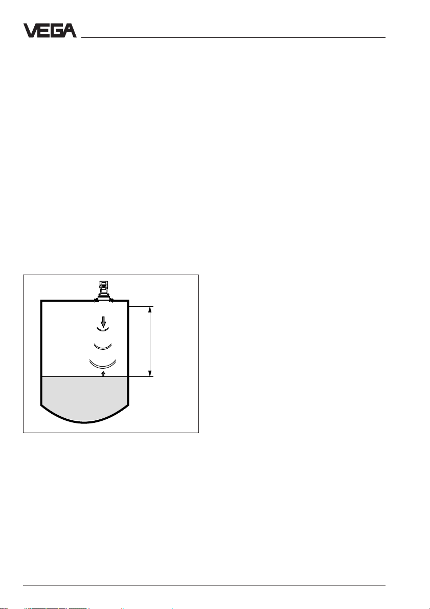
1.1 Function
The continuous level measurement with ultrasonic sensors is based on the running time
measurement of ultrasonic pulses.
Measuring principle
Piezoceramic high performance transducers
emit focused ultrasonic pulses which are
reflected by the surface of solids and liquids.
The measuring electronics prepare a precise
picture of the environment from the running
time and the signal form of the reflected ultrasonic pulses. The transducers work as transmitter and receiver. As receiver the transducers are high sensitivity piezo-microphones.
Meas.
distance
Product description
In order to be prepared for the different
measuring distances and requirements, the
instruments operate with emitting frequencies
of 34 kHz up to 70 kHz.
As the sound velocity is subjected to a temperature influence, the transducer also continuously detects the ambient temperature so
that the level is precisely provided even in
case of varying ambient temperature.
Output signals
The level proportional measuring signal is
provided as 4 … 20 mA-output signal.
The parameter adjustment of the analogue
4 … 20 mA-signal is individually possible and
reflects the measuring range or the adjusted
adjustment range of the sensor.
Measured value indication
If desired, an indicating instrument for direct
lobal survey can be mounted on to the series
50 ultrasonic sensors. The indicating instrument shows the precise level with the analogue bar-graph and with the digital figure. In
addition to the indication in the sensor itself,
you can have the level displayed with the
external indicating instrument VEGADIS 50
up to 25 m away from the sensor.
The external measured value indication oper-
emission - reflection - receipt
The measuring electronics precisely calculate
the distance between transducer and medium from the speed of sound and the actually detected running time of the emitted
sound impulse. The distance is then converted into a level proportional signal and
provided according to the sensor parameter
adjustment as precise scaled level.
4 VEGASON 51K … 53K
ates, like the integral indication, independent
of the 4 … 20 mA-output signal, and individual parameter adjustment is possible.
Page 5
Product description
1.2 Application features
Applications
• Level measurement of all liquids
• Level measurement of solids
(only short measuring distances) such as
e.g.:
coal, ore, stones, stone dust, cement,
gravel, crushed stones, sand, sugar, salt,
cereals, flour, granules, powder, dusts,
saw dust, wood chips
• Flow measurement on different flumes
• Gauge measurement, distance measurement, object monitoring and conveyor belt
monitoring
Two-wire technology
• Supply and output signal on one two-wire
line (Loop powered)
• 4 … 20 mA-output signal
Rugged and precise
• Unaffected by product features such as
density, conductivity, dielectric constant …
• Suitable for aggressive substances
• Measuring ranges 0,25 m … 15 m
Adjustment choice
• With adjustment software VEGA Visual
Operating (VVO) on PC
• With detachable adjustment module
MINICOM
• With the HART®-Handheld
• Measured value indication integrated in the
sensor
• Optional indication separate from the sensor
1.3 Adjustment
Each measuring distance is different, therefore each ultrasonic sensor must be given
some basic information on the application
and the environment, e.g. you need to inform
the sensor which level means “empty“ and
which level “full“. Apart from this “empty and
full adjustment“, a number of other adjustments can also be carried out with
VEGASON ultrasonic sensors.
The adjustment and parameter adjustment of
the ultrasonic sensors are carried out with
- the PC
- the detachable adjustment module MINICOM
- the HART®--Handheld
Adjustment with PC
The set-up and adjustment of the ultrasonic
sensors is generally made on the PC with the
adjustment program VEGA Visual Operating
(VVO) under Windows®.
The program leads quickly through the adjustment and parameter adjustment via pictures, graphics and process visualisations.
2
4 ...20 mA
2
Connection for each process
•G 11/2 A, 11/2" NPT
• G 2 A, 2" NPT
• Compression flange DN 100, ANSI 4"
Approvals
• CENELEC, ATEX, PTB, FM, CSA, ABS,
LRS, GL, LR, FCC
VEGASON 51K … 53K 5
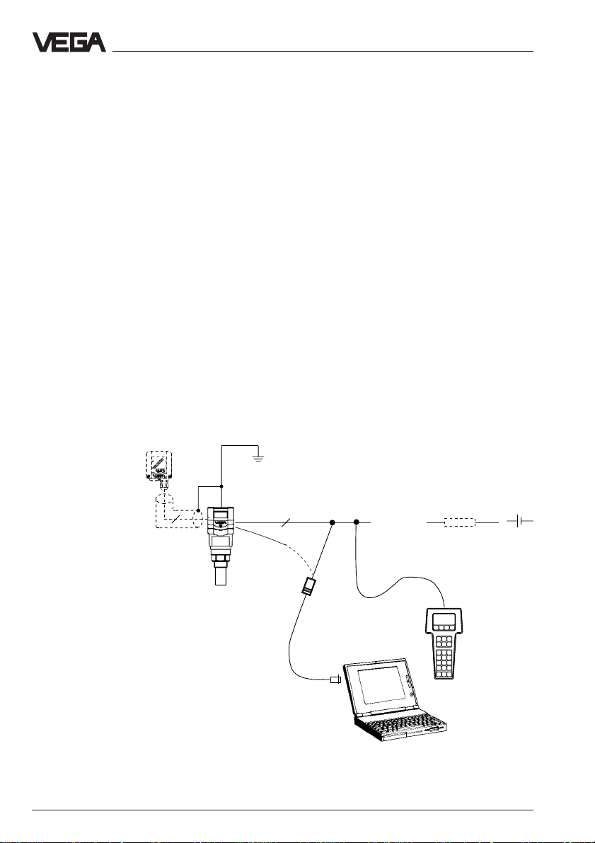
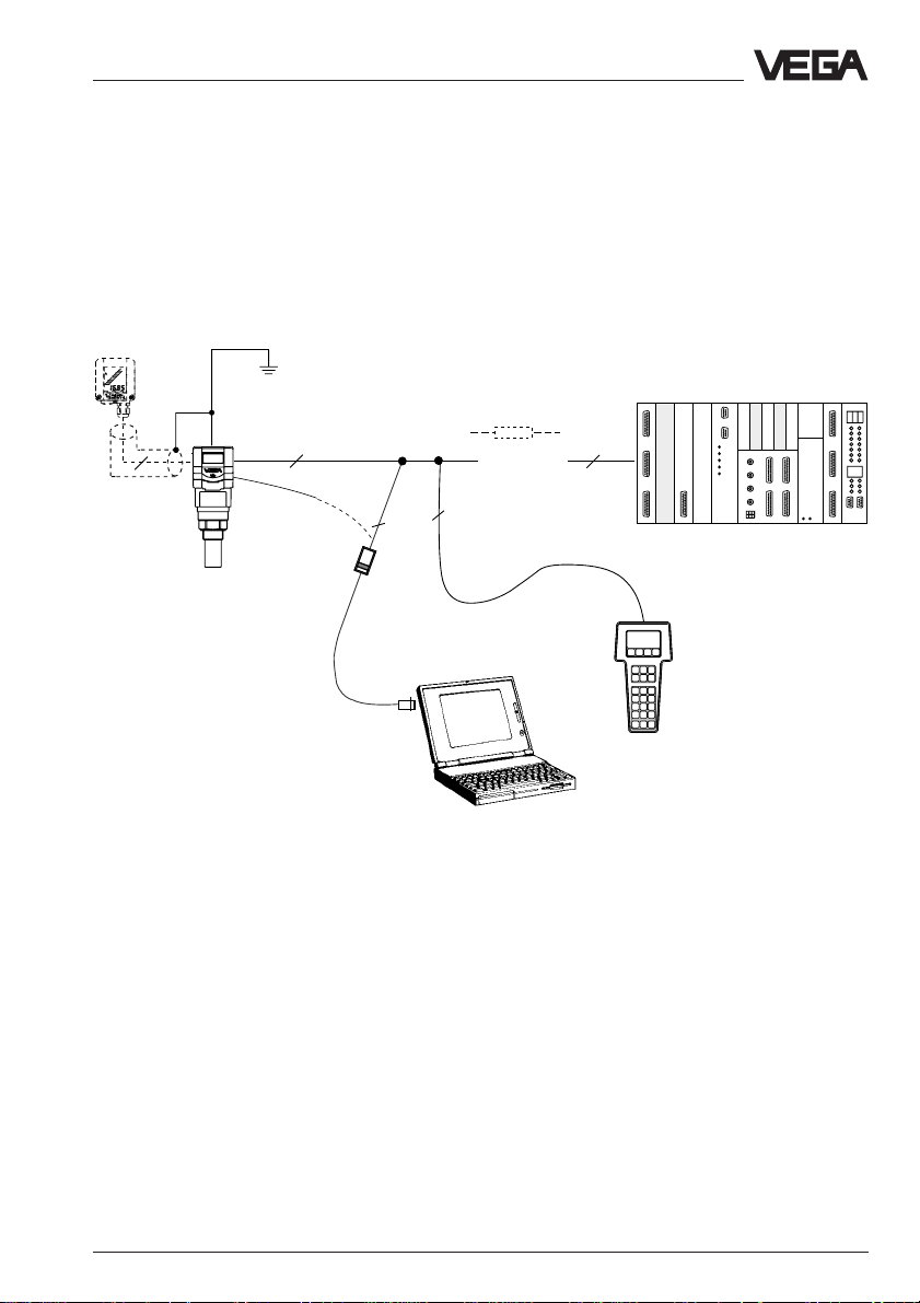
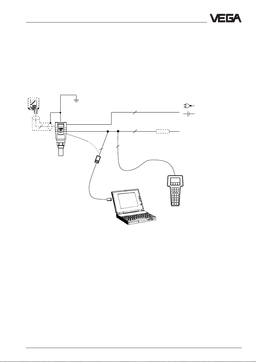
Adjustment with the PC on the analogue 4 … 20 mAsignal and supply line or directly on the sensor (fourwire sensor)
Page 6
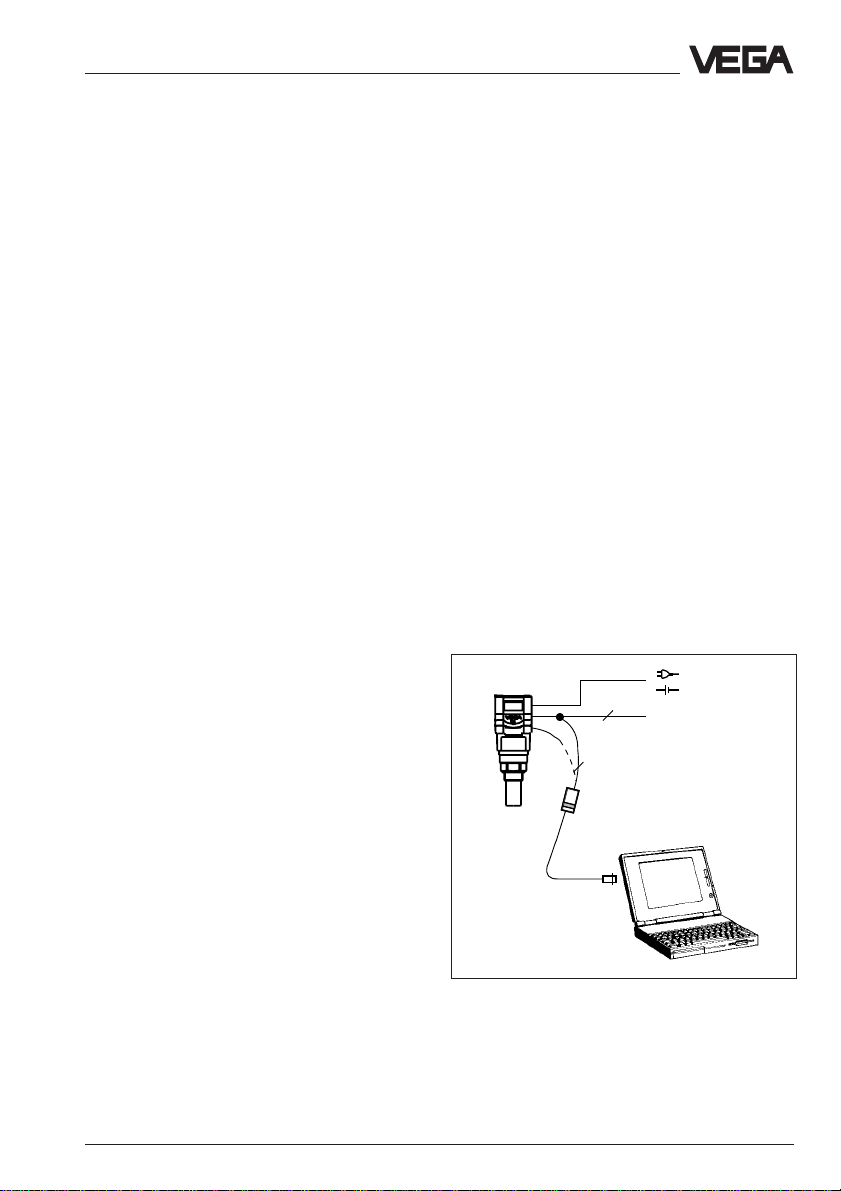
The PC can be connected to any individual
position of the system or the signal line. It is
thereby connected with the two-wire PCinterface converter VEGACONNECT 2 to the
sensor or to the signal line.
The adjustment and parameter adjustment
data can be saved with the adjustment software on the PC and protected with passwords. If required, the adjustment can be
transmitted quickly to other sensors.
The adjustment program recognises the sensor type
Product description
2
DCS
2
Adjustment with the PC on the 4 … 20 mA signal and
supply line to the DCS or directly on the sensor (in
the figure a two-wire sensor)
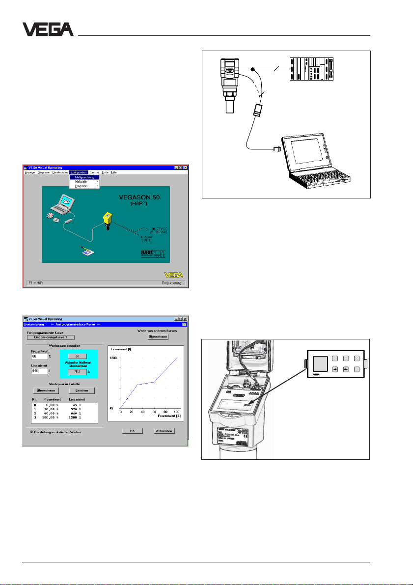
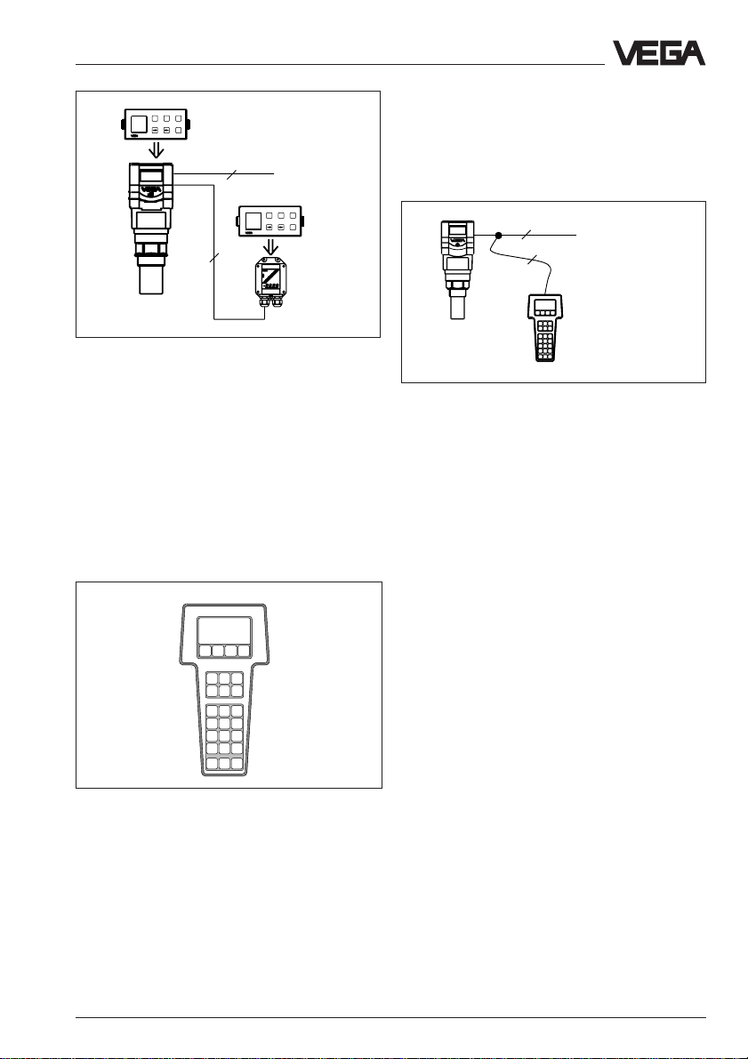
Adjustment with adjustment module
MINICOM
With the (3,2 cm x 6,7 cm) 6-key adjustment
module with display you can carry out the
adjustment in clear text.
The adjustment module can be plugged into
the ultrasonic sensor or into the optional
external indicating instrument.
Tank 1
m (d)
12.345
ESC
+
-
OK
Visualised input of a vessel linearisation curve
Detachable adjustment module MINICOM
By removing the adjustment module unauthorised adjustments are avoided.
6 VEGASON 51K … 53K
Page 7
Product description
ESC
+
-
Tank 1
m (d)
OK
12.345
2
4 ... 20 mA
ESC
+
-
Tank 1
m (d)
OK
12.345
4
Adjustment with the detachable adjustment module.
The adjustment module can be plugged into the
ultrasonic sensor or the external indication instrument
VEGADIS 50.
Adjustment with HART®-Handheld
Series 50 sensors with 4 … 20 mA output
signal can also be adjusted with the HART®Handheld. A special DDD (Data-DeviceDescription) is not necessary as the sensors
can be adjusted with the HART®-standard
menus of the handheld.
For adjustment, just connect the HART®Handheld in any position of the 4 … 20 mAoutput signal line or insert the two communication lines of the HART®-handheld into the
adjustment sockets on the sensor.
2
4 ... 20 mA
2
HART®-handheld on the 4 … 20 mA-signal line
HART Communicator
HART®-handheld
VEGASON 51K … 53K 7
Page 8
2 Types and versions
Types and versions
VEGASON series 50 sensors are a newly
developed generation of very compact, small
ultrasonic sensors. With very narrow space
requirements, they are designed for short
meas. distances (0 … 15 m) and for standard applications such as storage tanks,
gauge measurement and buffer tanks.
Due to the small housing dimensions and
process connections, the compact sensors
monitor your levels very price favourably.
With the integral indication and the many
features of the “big brothers“ of VEGASON
series 80, they offer the advantages of an
ultrasonic level measurement for applications
where the special advantages of a non-contact measurement are not applicable for price
reasons.
VEGASON 50 ultrasonic sensors control the
two-wire technology perfectly. The supply
voltage and the output signal are transmitted
via a two-wire line. An analogue 4 ... 20 mAoutput signal is available as output or measuring signal.
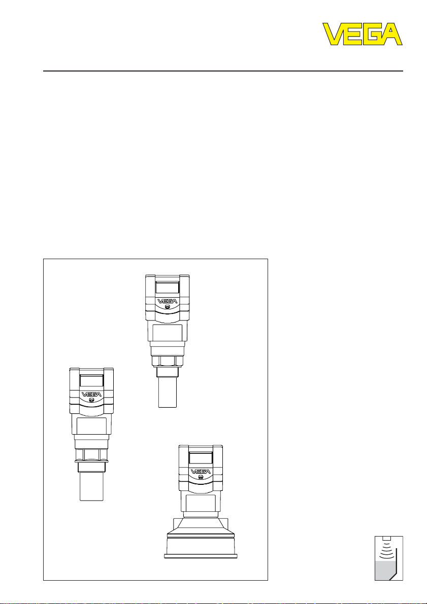
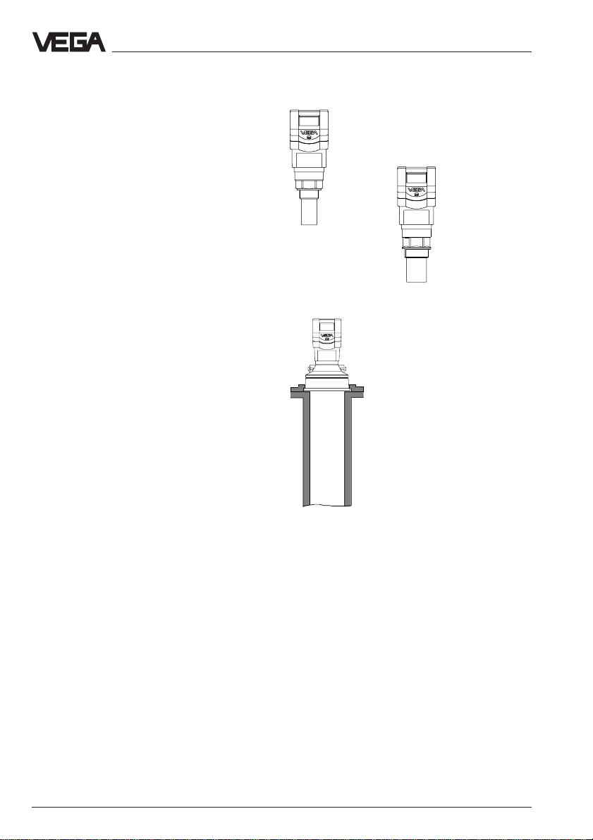
VEGASON 51
with 11/2“ thread
VEGASON 53
for mounting with holding strap or DN
100 compression flange (here on a
standpipe)
VEGASON 52
with 2“ thread
2.1 Type survey
General features
• Application in solids and liquids
• Measuring range 0,25 … 15 m
• Ex-approved in Zone 1 (IEC) or Zone 1 (ATEX) classification
EEx ia [ia] IIC T6
• Integral measured value indication
8 VEGASON 51K … 53K
Page 9
Types and versions
Survey VEGASON …
51K 52K 53K
Signal output
– active (4 … 20 mA) • • •
– passive (4 … 20 mA) • • –
Voltage supply
– two-wire technology (voltage supply and
signal output via a two-wire line) • • –
– four-wire technology (voltage supply separated
from the signal line) • • •
Process connection
1
–G1
/2 A; 11/2“ NPT • – –
– G 2 A; 2“ NPT – • –
– DN 100 compression flange – – •
Adjustment
–PC • • •
– adjustment module in the sensor • • •
– adjustment module in external indicating instrument • • •
– HART®-handheld • • •
Measuring range in m
– liquids 0,25 … 4 0,4 … 7 0,6 … 15
– solids 0,3 … 2 0,25…3,5 0,75 … 7
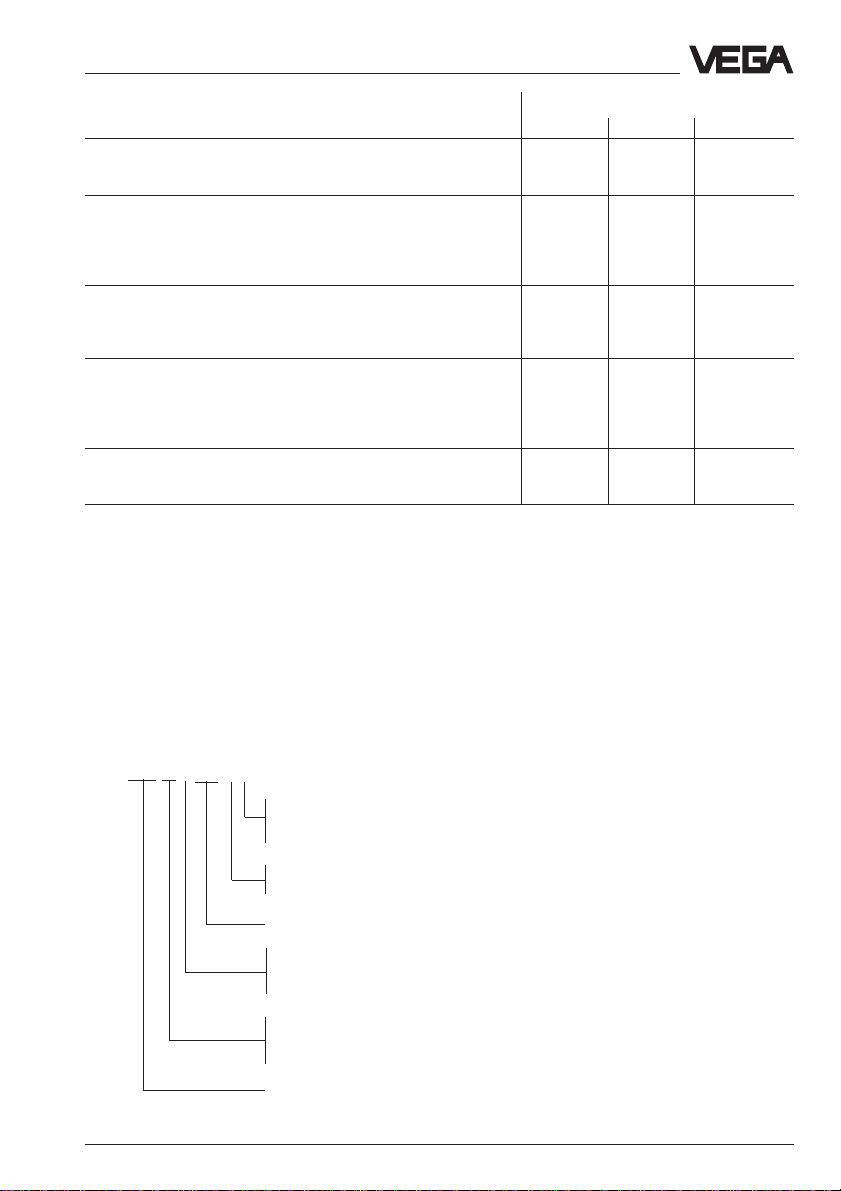
Type code
The second letter of the type designation e.g.
VEGASON 5[1]… differentiates the instruments acc. to process connection and measuring range.
The letter e.g. VEGASON 51[K] characterises
the output signal:
K stands for an analogue 4 … 20 mA output
signal (compact instrument).
VEGASON 51 K E X . X X (example)
P - 90 … 250 V AC (only in USA)
N - 20 … 36 V DC, 24 V AC (only in USA)
Z - supply via signal conditioning instrument (only in USA)
U - only in USA
X - outside the USA
Ex approved
K - Analogue 4 … 20 mA output signal
(two-wire or four-wire technology)
V - Digital output signal (two-wire technology)
Type 51: Measuring range 0,25 … 4 m
Type 52: Measuring range 0,4 … 7 m
Type 53: Measuring range 0,6 … 15 m
Measuring principle (SON for ultrasonic)
VEGASON 51K … 53K 9
Page 10
Types and versions
2.2 Configuration of meas. systems
Meas. systems in two-wire technology:
• 4 … 20 mA drawing without processing
unit,
A meas. system consists of a sensor with a
4 … 20 mA signal output and a unit evaluating or processing the level proportional current signal.
On the following pages you will see the instrument configurations called meas. system
which are shown in the following partly with a
signal processing.
(bottom)
• 4 … 20 mA on active DCS,
(page 12)
• 4 … 20 mA on active DCS (Ex-area),
(page 13)
• 4 … 20 mA on passive DCS,
(page 14)
• 4 … 20 mA on indicating instrument
VEGADIS 371 Ex,
(page 15)
Meas. systems in four-wire technology:
• 4 … 20 mA drawing without signal conditioning instrument, (page
16)
Meas. systems with VEGASON 51K … 53K
• Two-wire technology (loop powered), supply and output signal via a two-wire line
• Output signal 4 … 20 mA (passive)
• Optional external indicating instrument with analogue and digital indication (can be mounted
up to 25 m away from the sensor)
• Adjustment with PC, HART®-handheld or adjustment module MINICOM (can be plugged into
the sensor or in the external indicating instrument VEGADIS 50)
VEGADIS 50
4
2
VEGACONNECT 2
1)
If the resistors of the processing
systems connected to the
4 … 20 mA-signal output are less
than 200 Ω, a resistor of 250 Ω to
350 Ω must be connected to the
connection line during adjustment.
The digital adjustment signal would
be extremely damped or shortcircuited via too small input
resistors of the connected
processing system which means
that the digital communication with
the PC could no longer be
ensured.
10 VEGASON 51K … 53K
4 … 20 mA
1)
HART®-handheld
+
-
Page 11
Types and versions
Measuring system with VEGASON 51K … 53K on active DCS
• Two-wire technology, supply on active DCS.
• Output signal 4 … 20 mA (passive).
• Measured value indication integrated in the sensor.
• Optional external indicating instrument (can be mounted up to 25 m away from the sensor
in Ex-area).
• Adjustment with PC, HART®-handheld or adjustment module (can be plugged in the sensor
or in the external indicating instrument).
VEGADIS 50
1)
4
2
VEGACONNECT 2
4 … 20 mA
2)
passive
2
2
2
DCS
HART®-handheld
1)
If the resistors of the processing systems
connected to the 4 … 20 mA-signal output are less
than 200 Ω, a resistor of 250 Ω to 350 Ω must be
connected to the connection line during adjustment.
The digital adjustment signal would be extremely
damped or short-circuited via too small input
resistors of the connected processing system
which means that the digital communication with
the PC could no longer be ensured.
2)
4 … 20 mA passive means that the sensor takes,
depending on the level a current of 4 … 20 mA.
The sensor therefore reacts electrically like a
resistor (consumer) on the DCS.
VEGASON 51K … 53K 11
Page 12
Types and versions
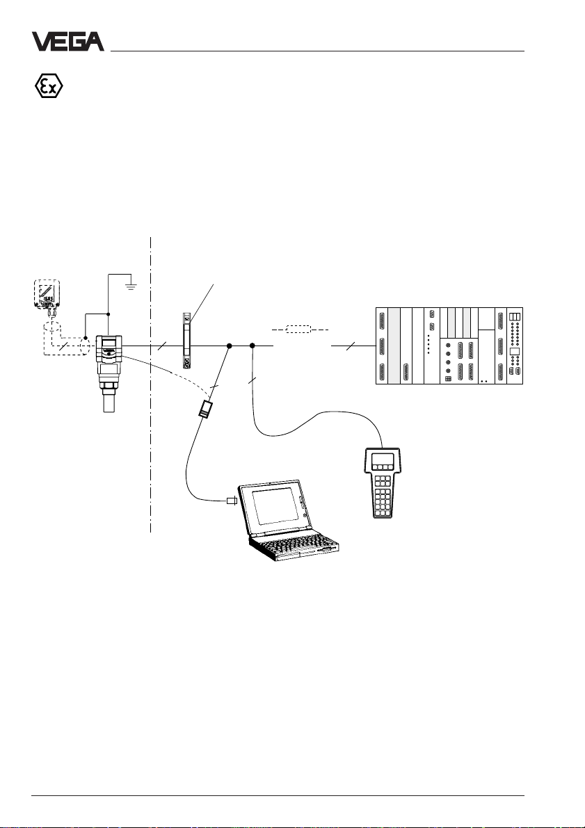
Measuring system with VEGASON 51K … 53K via separator in Ex-area on
active DCS
• Two-wire technology (loop powered), supply via the signal line on the DCS; output signal
4 … 20 mA (passive)
• Separator converts the not-intrinsically safe DCS-circuit into an intrinsically safe circuit, the
sensor can therefore also be used in Ex-zone 1
• Optional external indicating instrument with analogue and digital indication (can be mounted
up to 25 m away from the sensor)
• Adjustment with PC, HART®-handheld or adjustment module MINICOM (can be plugged in
the sensor or in the external indicating instrument VEGADIS 50)
Ex-area
VEGADIS 50
4
1)
If the resistors of the processing systems
Not Ex-area
2
Separator (e.g. Stahl)
(see "3.2 Approvals“)
2
2
VEGACONNECT 2
1)
4 … 20 mA
2)
passive
2
DCS active
HART®-handheld
connected to the 4 … 20 mA-signal output are less
than 200 Ω, a resistor of 250 Ω to 350 Ω must be
connected to the connection line during adjustment.
The digital adjustment signal would be extremely
damped or short-circuited via too small input
resistors of the connected processing system
which means that the digital communication with
the PC could no longer be ensured.
2)
4 … 20 mA passive means that the sensor takes a
current of 4 … 20 mA depending on the level. The
sensor, therefore, reacts electrically like a resistor
(consumer) on the DCS. The DCS operates
actively, i.e. as current or voltage supply.
12 VEGASON 51K … 53K
Page 13
Types and versions
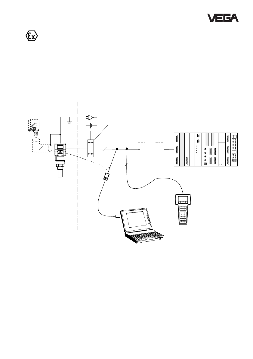
Measuring system with VEGASON 51K … 53K vi a separator (Smart-Transmitter) on passive DCS
• Two-wire technology (loop powered), intrinsically ia-supply via the signal line from the separator for operation of the sensor in Ex-Zone 1
• Output signal sensor 4 … 20 mA passive
Output signal separator 4 … 20 mA active
• Optional external indicating instrument with analogue and digital indication (can be mounted
up to 25 m away from the sensor)
• Adjustment with PC, HART®-handheld or adjustment module MINICOM (can be plugged in
the sensor or in the external indicating instrument VEGADIS 50)
VEGADIS 50
4
Ex-area
Not Ex-area
-
+
Separator (e.g. VEGATRENN 149 Ex see
"3.2 Approvals“)
1)
2
2
VEGACONNECT 2
2
4 … 20 mA
2)
(active)
DCS (passive)
HART®-handheld
3)
1)
If the resistors of the processing systems
connected to the 4 … 20 mA-signal output are less
than 200 Ω, a resistor of 250 Ω to 350 Ω must be
connected to the connection line during adjustment.
The digital adjustment signal would be extremely
damped or short-circuited via too small input
resistors of the connected processing system
which means that the digital communication with
2)
4 … 20 mA active means that the separator
delivers level dependent a current of 4 … 20 mA.
The separator therefore reacts electrically against
the DCS like a current source.
3)
4 … 20 mA passive means that the sensor takes,
a current of 4 … 20 mA, depending on the level.
The sensor therefore reacts electrically like a
resistor (consumer) on the DCS.
the PC could no longer be ensured.
VEGASON 51K … 53K 13
Page 14
Types and versions
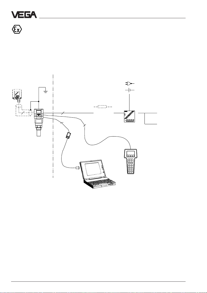
Measuring system with VEGASON 51K … 53K on the indicating instrument
VEGADIS 371 Ex with current and relay output
• Two-wire technology (loop powered), intrinsically safe ia-supply via the signal line from the
indicating instrument VEGADIS 371 Ex for operation of the sensor in Ex-zone 1
• Optional external indicating instrument with analogue and digital indication (can be mounted
up to 25 m away from the sensor)
• Adjustment with PC, HART®-handheld or adjustment module MINICOM (can be plugged in
the sensor or in the external indicating instrument VEGADIS 50)
Ex-area
VEGADIS 50
4
Not Ex-area
2
2
VEGACONNECT 2
4 ... 20 mA
2
1)
(passive)
-
+
VEGADIS
371 Ex
(see "3.2 Approvals“)
HART®-handheld
Relay
0/4 … 20 mA
1)
If the resistors of the processing systems
connected to the 4 … 20 mA-signal output are less
than 200 Ω, a resistor of 250 Ω to 350 Ω must be
connected to the connection line during adjustment.
The digital adjustment signal would be extremely
damped or short-circuited via too small input
resistors of the connected processing system
which means that the digital communication with
the PC could no longer be ensured.
14 VEGASON 51K … 53K
Page 15
Types and versions
Measuring system with VEGASON 51K … 53K in four-wire technology
• Four-wire technology, supply and output signal via two separate two-wire lines
• Output signal 4 … 20 mA active
• Optional external indicating instrument with analogue and digital indication (can be mounted
up to 25 m away from the sensor)
• Adjustment with PC, HART®-handheld or adjustment module MINICOM (can be plugged in
the sensor or in the external indicating instrument VEGADIS 50)
• Max. resistance on the signal output (load) 500 Ω
VEGADIS 50
2
-
4
2
2
2
VEGACONNECT 2
1)
> 200 Ω
+
4 … 20 mA
2)
(active)
HART®-handheld
1)
If the resistors of the processing systems
connected to the 4 … 20 mA-signal output are less
than 200 Ω, a resistor of 250 Ω to 350 Ω must be
connected to the connection line during adjustment.
The digital adjustment signal would be extremely
damped or short-circuited via too small input
resistors of the connected processing system
which means that the digital communication with
the PC could no longer be ensured.
2)
4 … 20 mA active means that the sensor delivers
a current of 4 … 20 mA (source) depending on the
level. The sensor, therefore, reacts electrically
against a processing system (e.g. indication) like a
current source.
VEGASON 51K … 53K 15
Page 16
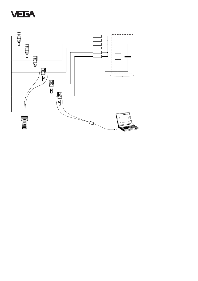
Several sensors on a voltage source
250 Ω
250 Ω
250 Ω
250 Ω
250 Ω
250 Ω
Types and versions
C
R = 0…2 Ω
All sensors are dispatched with the same
communication address zero. If several sensors are operated on one voltage source, a
resistors avoid the adjustment signals of the
actually operated sensor from also being
short-circuited.
communication on the signal line with the PC
or with the HART®-handheld is no longer
possible, as in this case all sensors are addressed digitally at the same time.
With the PC and the adjustment software
VEGA Visual Operating (VVO) or with the
HART®-handheld, the sensors can be ad-
justed from the address zero to the address
To avoid this, 250 Ω … 350 Ω resistors must
be connected directly on the voltage source
in the sensor supply line. The inner resistance of the voltage source must be very
small. The digital communication signal (PC
or HART®-handheld) used on the sensor line,
1 … 15. If a sensor is adjusted to the ad-
dress 1 … 15, the sensor no longer delivers
a 4 … 20 mA-signal, but is frozen to 4 mA
(power supply). Nevertheless, the sensor will
continue to provide the measured value digit-
ally. This mode is called multidrop operation.
is then no longer transmitted to the other
sensors. You can then communicate with the
PC or HART®-handheld on the signal line of
the appropriate sensor without the participation of all other sensors in the communication
even though all sensors react to the address
zero. The low inner resistor (alternating load
resistor by filter capacitor) of the voltage
source short-circuits the signals before they
can cross over to the other sensor lines. The
16 VEGASON 51K … 53K
Page 17
Technical data
3 Technical data
3.1 Data
Power supply
Supply voltage
- four-wire sensor 230 V AC (20 … 250 V AC), 50/60 Hz
- two-wire sensor 24 V DC (16 … 36 V DC); Sicherung 0,2 A TR
Diagram of the min. supply voltage dependent on the
V
sensor current (two-wire sensor)
36
29
16
14
24 V DC (20 … 72 V DC)
fuse 0,2 A TR
Range of the required and permissible terminal voltage
Ex-voltage limit
0
422
mA
Current consumption
- two-wire sensor max. 22,5 mA
- four-wire sensor max. 140 mA
Power consumption
- two-wire sensor max. 80 mW, 0,45 VA
- four-wire sensor max. 1,2 W, 2,50 VA
Load
- four-wire sensor max. 500 Ω
- two-wire sensor see diagram
Ω
Load diagram of the two-wire sensor
(loop resistor of processing unit, e.g. DCS and supply line)
1000
900
800
700
680
600
500
HART®-
400
load
300
250
200
100
0
16 20 25 30 35
min. voltage limit
by using the
HART®-load
17 18 19 29
VEGASON 51K … 53K 17
max. voltage
limit with
Ex-sensors
max. voltage limit
with not-Ex-sensors
V
36
Page 18

Technical data
Type 51… 52… 53…
Measuring range (relating to the transducer surface)
Liquid 0,25 … 4 m 0,4 … 7 m 0,6 … 15 m
Solid 0,30 … 2 m 0,5 … 3,5 m 0,75 … 7 m
Output signal
Analogue 4 … 20 mA-current signal
Adjustment
- PC with adjustment software VEGA Visual Operating
- adjustment module MINICOM
- HART®-handheld
Accuracy (typical values under reference conditions)
1)
Class accuracy (deviation in characteristics
including repeatability and hysteresis
acc. to the limit point method) < 0,1 % relating to max. measuring range
Temperature drift (relating to 20°C) < 0,015 %/10 K of measuring range
Accuracy of the 4 … 20 mAoutput signal 0,025 % (D/A-converter)
Resolution 1 mm
Characteristics
Min. span
(between empty and full adjustment) > 20 mm (recommended > 50 mm)
Ultrasonic frequency 70 kHz 55 kHz 34 kHz
Intervals 1,0 s 1,0 s 1,0 s
Beam angle
(at -3 dB emitted power) 5,5° 5,5° 3°
Response time
2)
2 … 20 s
(dependent on the factory setting)
Materials
Housing PBT (Valox)
Transducer, process connection thread PVDF
Compression flange PP or 1.4571
Transducer diaphragm (type 53) 1.4571
Weights
Weight incl. transducer
- VEGASON 51 1,2 kg
- VEGASON 52 1,6 kg
- VEGASON 53 2,3 kg
1)
Reference conditions acc. to IEC 770, e.g.: Temperature 18°C … 30°C etc.
2)
The response time is the time the sensor requires to provide the level correctly with a quick level change
(with max. 10 % deviation).
18 VEGASON 51K … 53K
Page 19
Technical data
Ambient conditions
Max. vessel pressure (gauge pressure)
- VEGASON 51 and 52 3 bar
- VEGASON 53 1 bar
Ambient temperature
- sensor (electronics) -20°C … +60°C
- process (transducer) -40°C … +80°C (StEx: -20°C … +75°C)
- storage and transport temperature -40°C … +80°C
Protection
- sensor IP 67
- transducer, process IP 68
Protection class
- two-wire sensor II
- four-wire sensor I
Overvoltage category III
Self-heating
at 40°C ambient temperature
- to sensor 45°C
- to transducer, process 55°C
Ex-technical data
Classification ia intrinsically safe (in conjunction with a safety
barrier or separator)
Temperature class (permissible ambient
temperature on the transducer when used
in Ex-areas)
- T6 42°C
- T5 58°C
- T4 60°C
- T3 60°C
Ex-approved in category or zone
- ATEX Zone 1 (II 2 G)
- IEC, CENELEC, PTB Zone 1 (II 2 G)
Classification mark EEx ia IIC T6
Process connections
VEGASON 51 G 11/2 A, 11/2" NPT
VEGASON 52 G 2 A, 2" NPT
VEGASON 53 DN 100 compression flange
Connection lines
Two-wire sensors supply and voltage via one two-wire line,
load dependent on the supply voltage
Four-wire sensor supply and signal separately, load of the
Cross-section area of conductor generally 2,5 mm
4 … 20 mA-signal line max. 500 Ω
Earth connection max. 4 mm
2
2
Cable entry, Pg 2 x M20 x 1,5 (cable diameter 5 … 9 mm)
VEGASON 51K … 53K 19
Page 20

Technical data
CE-conformity
VEGASON series 50 ultrasonic sensors meet the protective regulations of EMVG
(89/336/EWG) and NSR (73/23/EWG). The conformity has been judged acc. to the following
standards:
EMVG Emission EN 50 081 - 1: 1993
NSR EN 61 010 - 1: 1993
Susceptibility EN 50 082 - 2: 1995
Outputs and processings
Display indication
Indication - optional integrated in the sensor, scalable
Signal output
Signal output
- two-wire technology 4 … 20 mA (load dependent on supply
- four-wire technology 4 … 20 mA (load max. 500 Ω)
Resolution of the 20 mA-signal 0,025 % of operating range
Failure of the 20 mA-signal < 0,025 % of operating range
analogue and digital meas. value indication
- optional external meas. value indication,
powered by the sensor and up to 25 m away
from the sensor (also the adjustment module
MINICOM can be inserted)
voltage, see load diagram page 17)
Two-wire technology:
The analogue 4 … 20 mA-output signal (measuring signal) is transmitted together with the
power supply via a two-wire line.
Four-wire technology:
Separate power supply.
The analogue 4 … 20 mA-output signal (measuring signal) is looped by a line separated
from the supply voltage.
20 VEGASON 51K … 53K
Page 21

Technical data
3.2 Approvals
When using ultrasonic sensors in Ex-areas or
navigation, the instruments must be suitable
and approved for the explosion zones and
application areas. The suitability is checked
by approval authorities and certified by approval documents.
VEGASON 50 ultrasonic sensors are approved for Ex-zone 1. Please note the attached approval documents when using a
sensor in Ex-area.
Test and approval authorities
VEGASON ultrasonic sensors are tested and
approved by the following monitoring, test
and approval authorities:
- PTB
(Physikalisch Technische Bundesanstalt Physical Technical Test Authority)
- FM
(Factory Mutual Research)
- ABS
(American Bureau of Shipping)
- LRS
(Lloyds Register of Shipping)
- GL
(German Lloyd)
- CSA
(Canadian Standards Association)
Ex-area zone 1
Series 50 senors require special safety barriers and separators for operation in Ex-area
zone 1. The safety barriers and separators
provide intrinsically safe (ia) circuits. The
followes shows a choice of instruments with
which the series 50 sensors work reliably.
The signal line resistance must not exceed
15 Ω per wire.
Separators and signal conditioning instrument:
- VEGADIS 371 Ex
- A puissance 3 PROFSI 37-24070A
- VEGAMET 614 Ex
- Apparatebau Hundsbach
AH MS 271-B41EEC 010
Separators:
- VEGATRENN 149 Ex…
- Stahl 9303/15/22/11
- CEAG GHG 124 3111 C1206
Separators, safety barriers:
- Stahl 9001/01/280/110/10
- CEAG GHG 11 1 9140 V0728
- Type 9130 (VEGA)
- Stahl 9001/51/280/110/14
- MTL 787 S+
- CEAG CS 3/420-106
VEGASON 51K … 53K 21
Page 22

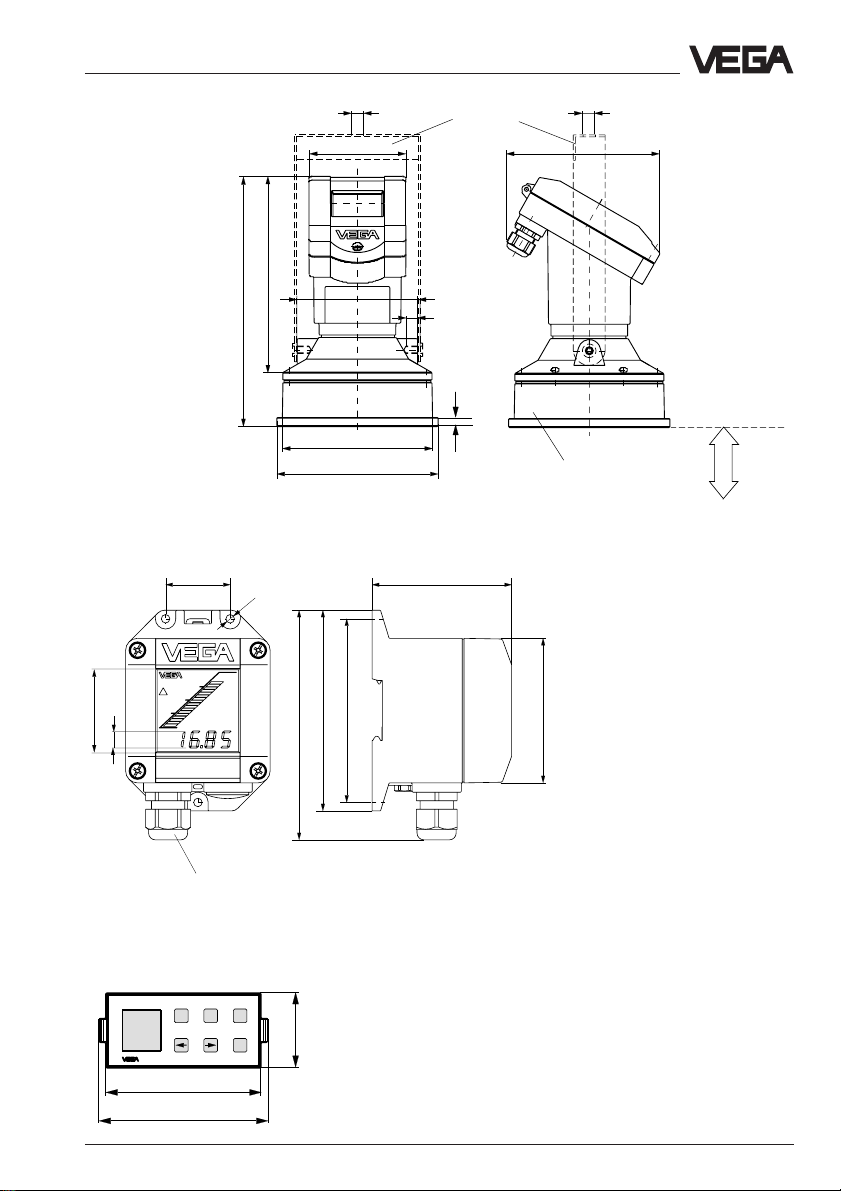
3.3 Dimensions
VEGASON 51
Technical data
95
152
VEGASON 52
206
202
22
65
2 x M20x1,5
Thread G 11/2 A or 11/2“
NPT
Reference plane
ø39
ø60
85
95
Min.-distance
to the medium
152
0,25 m
Thread G 2 A or 2" NPT
22
61
ø50
ø72
85
SW 60
Min.-distance
to the medium
Reference plane
0,4 m
22 VEGASON 51K … 53K
Page 23
Technical data
193
ø158
152
95
247
ø148
12
M8x10
ø12
ø12
120
0,6 m
VEGASON 53
External indicating instrument VEGADIS 50
38
5
ø
82
Mounting loop
suitable for compression
flange DN 100
Min.-distance
to the medium
48
10
135
118
108
85
Note:
Cable diameter of the connection cable min.
5 mm and max. 9 mm.
Otherwise the seal effect of the cable entry is
not ensured.
-
Pg 13,5
+
ESC
OK
Carrier rail mounting 35 x 7,5 acc. to EN 50 022 or flat
screwed
Adjustment module MINICOM
Tank 1
m (d)
12.345
32,5
Adjustment module for insertion into
VEGASON series 50 sensors or into the external indicating instrument VEGADIS 50
67,5
74
VEGASON 51K … 53K 23
Page 24
4 Mounting and installation
Mounting and installation
4.1 General installation instructions
Measuring range
You select your instrument according to the
required measuring range, as well as other
criteria. The reference planes for the min. and
on instruments with flange version, the instrument flange. (Note the information for the
reference planes in chapter "Dimensions“).
The max. filling is dependent on the required
min. distance of the instrument used (0,25 m
to 1,4 m) and the installation place of the
instrument or the transducer.
max. distance to the product or the solid is
either the transducer surface (diaphragm) or,
Typ e 5 1
Min.
distance
0,25 m 0,4 m
Min. distance, max. measuring range and span (example VEGASON 51, 52 and 53)
Full
1m
max. meas. range
4 m (type 51), 7 m (type 52), 15 m (type 53)
Empty
Min.
distance
0,75 m
Typ e 5 3 Typ e 52
Reference plane
Span
Min.
distance
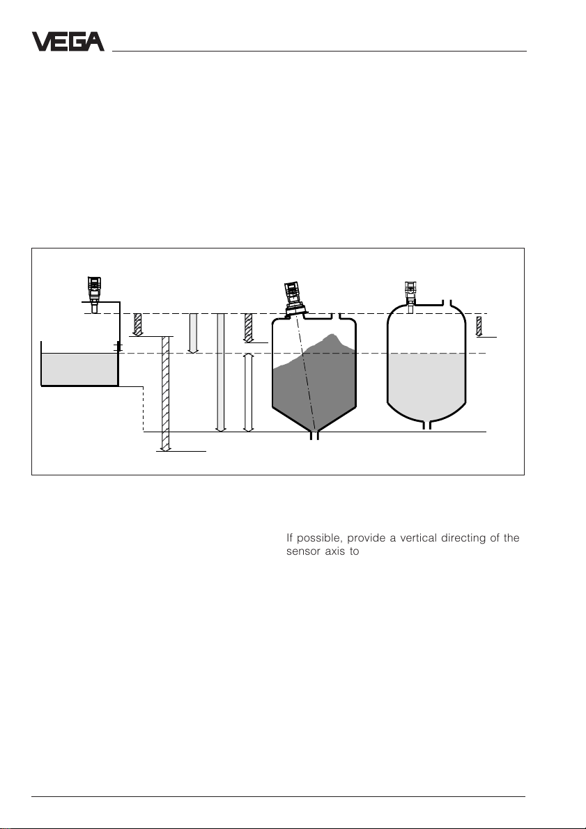
Beam angle and false echoes
If possible, provide a vertical directing of the
sensor axis to the product surface and
The ultrasonic impulses are focussed by the
transducer. The impulses leave the trans-
avoid, if possible, struts within the 100 %-
beam, e.g. by tubes and struts.
ducer in conical form similar to the beam
pattern of a spotlight. The beam angle is 5,5°
(VEGASON 51/52) or 3° (VEGASON 53) at
-3 dB emitted power.
Any object in this beam angle causes a false
echo. Within the first few metres of the beam
angle, tubes, struts or other installations
cause strong false echoes. At a distance of 6
m the false echo of a strut has 9-times more
amplitude than at a distance of 18 m.
24 VEGASON 51K … 53K
Page 25

Mounting and installation
Meas. distance
0 m
4 m
7 m
Meas. distance
0 m
VEGASON 51/52
0,4
VEGASON 53
4.2 Measurement of liquids
Flat vessel top
On flat vessels the mounting is mainly made
on a very short DIN-socket piece. Reference
5,5˚
12˚
50 %
emitted power
100 %
emitted power
0
1,21,2
0,4
3˚
8˚
emitted power
50 %
m
plane on flange versions is the instrument
flange. The transducer should protrude out of
the flange pipe.
Reference plane
≤ 60 mm
Min.
distance
Flange version on very short DIN-socket piece
Ideal is the mounting directly on the vessel
top. A round opening on the vessel is sufficient to fasten the VEGASON 53 sensor with
a compression flange.
emitted power
100 %
Reference plane
15 m
0,4
1,2
0,4
0
m
1,2
Flange version (compression flange) on flat vessel
top
VEGASON 51K … 53K 25
Page 26

You can also mount the sensors with 11/2“ or
2“ thread to short socket pieces.
≤ 60 mm
Reference plane
≤ 60 mm
Mounting and installation
Reference
plane
1
/2 vessel radius
Mounting on short 11/2“ or 2“ socket piece
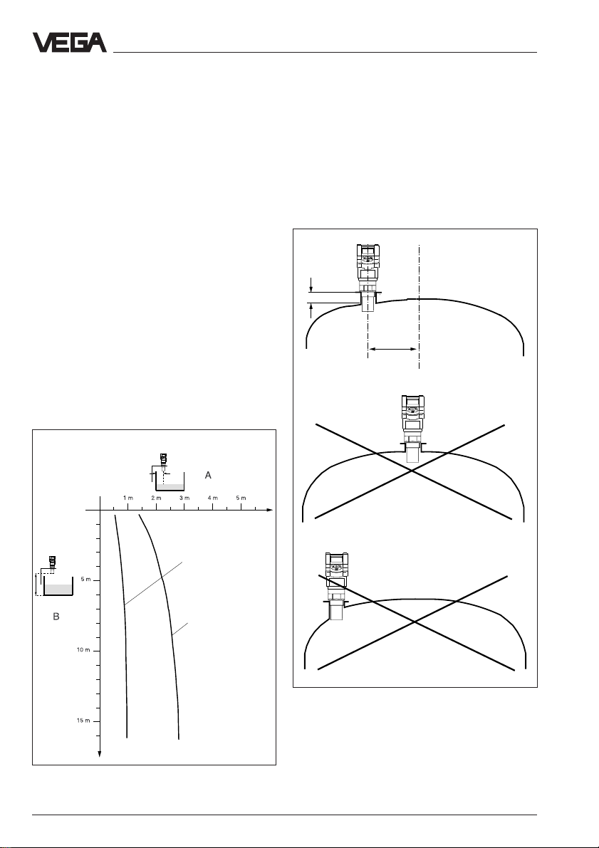
Dished tank ends
On dished tank ends, please do not mount
the instrument in the centre but approx. 1/2
vessel radius from the centre. Dished tank
ends can act as paraboloidal reflectors for
the ultrasonic pulses. If the transducer is
placed in the "focus" of the parabolic tank
end, the transducer receives amplified false
echoes. The transducer should be mounted
outside the "focus". Parabolic amplified echoes are thereby avoided.
≤ 60 mm
Reference plane
1
/2 vessel radium
Flange on dished vessel ends
Open vessles
On open vessels the use of the instruments
on a mounting lever is recommended. Mount
the low-weight sensor to a mounting lever.
Reference plane
Min. meas.
distance
Open vessels
Mounting boss on dished tank ends
26 VEGASON 51K … 53K
Page 27

;;;;;;;;;;;;;
Mounting and installation
Pump shaft
Narrow shafts and shaft openings (vessel
openings) with very rough walls and shoulders aggravate an ultrasonic measurement
due to strong false echoes.
Shaft and vessel openings
Narrow, very rough shaft, well and vessel
openings can be overcome by a socket
piece as described under "4.4 Socket extensions“ (left lower half of the figure).
see also “4.4 Socket
extension“
Socket piece
> 100 mm
min.
distance
Measuring
Shaft
You can realise very good meas. results with
a meas. pipe in continous narrow shafts, see
figure. The meas. pipe used must have
smooth walls inside (e.g. PE-sewage pipe)
and a diameter of ≥100 mm. This coordination
works without problems as long as the inside
of the meas. pipe has no build-up (cleaning).
Also check the use of hydrostatic pressure
transmitters or capacitive electrodes.
4.3 Measurement of solids
Flange mounting
As with liquids, the instrument can also be
mounted on a short DIN-socket piece in solid
vessels. The socket axis must point to the
vessel outlet or should be directed vertically
to the product surface and must be very
short (< 100 mm).
Reference plane
range
Shaft pump
Meas. tube
Socket piece or meas. tube on the example of a shaft
VEGASON 51K … 53K 27
Shaft pump
VEGASON 53 on vessel flange
Min. distance
Page 28

Swivelling holder
The accessory programme offers a swivelling holder (mounting loop) for mounting of
the VEGASON 53. This facilitates the directing of the sensor to the product surface.
Reference plane
Min. distance
VEGASON 53 on swivelling holder
Mounting and installation
Reference plane
Min. distance
VEGASON 51 or 52 on the mounting boss. The socket
axis should point to the product surface
Material cones
Large material cones are detected with several instruments which can be fastened on
lifting beams.
Mounting boss
Reference plane
Max.
Transducer on lifting beam above material cone
VEGASON 52 on mounting boss
28 VEGASON 51K … 53K
Page 29

Mounting and installation
;
;
;
;
;
;
;
;
4.4 Socket extensions
The ultrasonic sensor requires a min. distance to the product or solid. Note this min.
distance in your planning.
In exceptions it is possible to reach the required min. distance and hence the desired
filling height with a socket piece. However,
the socket piece increases the noise level of
the ultrasonic signal and can interfere with the
measurement. Only provide the socket extension when there is no other possibility, and
carry out the extension as shown in the following figure.
Socket extension with liquids
Chamfer the socket carefully and ensure a
smooth inner side of the socket. The socket
should not protrude into the measured product when pollution or measured product
could stick to the socket.
;;;;;;;;;;;;;;;
;;;;;;;;;;;;;;;
;;;;;;;;;;;;;;;
;;;;;;;;;;;;;;;
;;;;;;;;;;;;;;;
;;;;;;;;;;;;;;;
;;;;;;;;;;;;;;;;
;;;;;;;;;;;;;;;
For measurements in products which do not
cause any build-up, the socket extension, in
form of a meas. pipe, can be permanently
submerged into the measured product. The
ultrasonic mesurement is then only carried
out in the meas. pipe without being interfered
with by vessel installations (see page 28
"Pump shaft“).
Type 51/52
LL
45˚
ø
Socket extension with liquids
Typ e 5 3
45˚
ø
Max. socket length dependent on the socket
diameter
øL in mm
in mm Type 51 Type 52 Type 53
100 200 300 300
150 300 400 400
200 – 500 500
250 – – 600
Socket piece should not be submerged into the
adhesive product (figure: VEGASON 53)
Choose as large a socket diameter as possi-
Socket extension with solids
For solids provide a conical socket extension
with an angle of at least 15° … 20°.
ble and as small a socket length as possible.
Ensure that the socket opening is burr free to
minimise false echoes.
15˚
15˚
Socket extension with solids
VEGASON 51K … 53K 29
Page 30

Mounting and installation
4.5 Flow measurement
The short examples on this page only give
introductory information for your flow measurement. Planning information is given by the
flume manufacturers and in special literature.
Rectangular flume
- Installation of the sensor on the upstream
side
- Note distance to the overfall edge
(3 … 4 x h
- Installation centered to the flume
- Edge opening ≥ 2 x h
- Installation perpendicular to the liquid sur-
face
- Keep min. distance relating to h
- Min. distance of the edge opening of down-
stream water ≥ 50 mm
max
90°
)
from ground
max
max
≥ max.
distance
h
max
Khafagi-Venturi flume
- Installation of the sensor on the inlet side
- Note distance to the Khafagi-Venturi flume
(3 … 4 x h
- Installation perpendicular to the liquid surface
- Keep min. distance relating to the height of
damming h
Khafagi-Venturi flume
max
max
3 … 4 x h
90°
Sensor
)
max
h
max
B
≥ 2 x h
Overfall edge
max
Flow measurement on open flumes
Overfall edge
3 … 4 x h
max
90°
≥ 5 cm
Upstream water
Downstream water
Flow measurement on open flumes
30 VEGASON 51K … 53K
Page 31

Mounting and installation
4.6 False echoes
The placing of the ultrasonic senor must be
chosen so as to ensure that no mountings or
in-flowing filling material crosses with the
ultrasonic impulses. The following examples
and instructions show the most frequent
measuring problems and how to avoid them.
Vessel protrusions
Vessel forms with flat protrusions can, due to
their strong false echoes, greatly effect the
measurement. The placing of shields over
these flat protrusions scatter the false echoes
and guarantee a definite measurement.
Correct Wrong
Vessel protrusions (slope)
Intake pipes, i.e. for the mixing of materials with the flat top turned towards the sensor should be covered with an angular shield
with which the false echoes are then scattered.
Vessel mountings
Vessel mountings such as, for example, a
ladder often cause false echoes. When projecting the measuring point, please ensure
the free access of the ultrasonic signals to
the medium.
Correct Wrong
Ladder
Vessel mountings
Ladder
Vessel struts
Vessel struts, as with other vessel mountings,
can cause strong false echoes which superimpose the useful echoes. Small shields
effectively hinder a direct false echo reflection. The false echoes are scattered and
diffused in the area and are then filtered out
as "echo noise" by the measuring electronics.
Correct Wrong
Correct Wrong
Vessel struts
Vessel protrusions (intake pipe)
VEGASON 51K … 53K 31
Shields
Page 32
Mounting and installation
;;
;;
;;
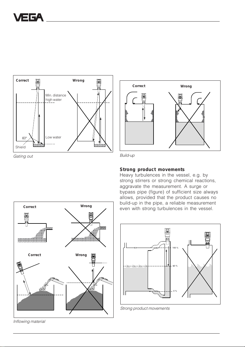
Flood basin
The max. height of water to be expected
determines the installation height to keep the
min. distance of the transducer even with
highest high water. The low water edge
should be covered with a shield in the transducer range.
Correct Wrong
Min. distance
high water
60°
Shield
Low water
Gating out of an echo
Inflowing material
Do not mount the instrument in or above the
filling stream. Ensure that you detect the
product surface and note the inflowing material.
Correct
Wrong
Mounting on the vessel
If the sensor is mounted too close to the
vessel wall, build-up and adhesion of the
filling material to the vessel wall cause false
echoes. Please position the sensor at a sufficient distance from the vessel wall. Please
also note chapter "4.1 General installation
instructions".
Correct
Build-up
Wrong
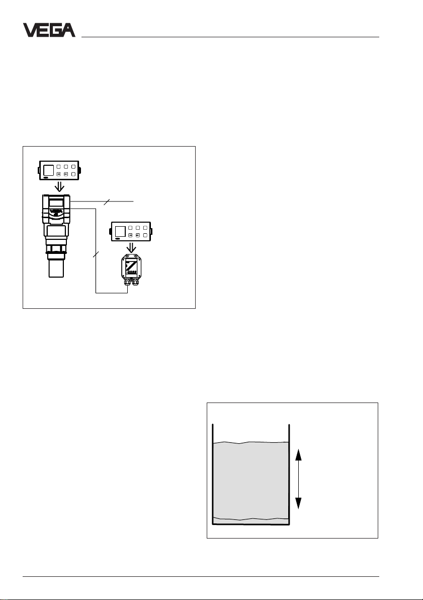
Strong product movements
Heavy turbulences in the vessel, e.g. by
strong stirrers or strong chemical reactions,
aggravate the measurement. A surge or
bypass pipe (figure) of sufficient size always
allows, provided that the product causes no
build-up in the pipe, a reliable measurement
even with strong turbulences in the vessel.
Correct
Wrong
Strong product movements
Inflowing material
32 VEGASON 51K … 53K
Page 33
Mounting and installation
;
;
;
;
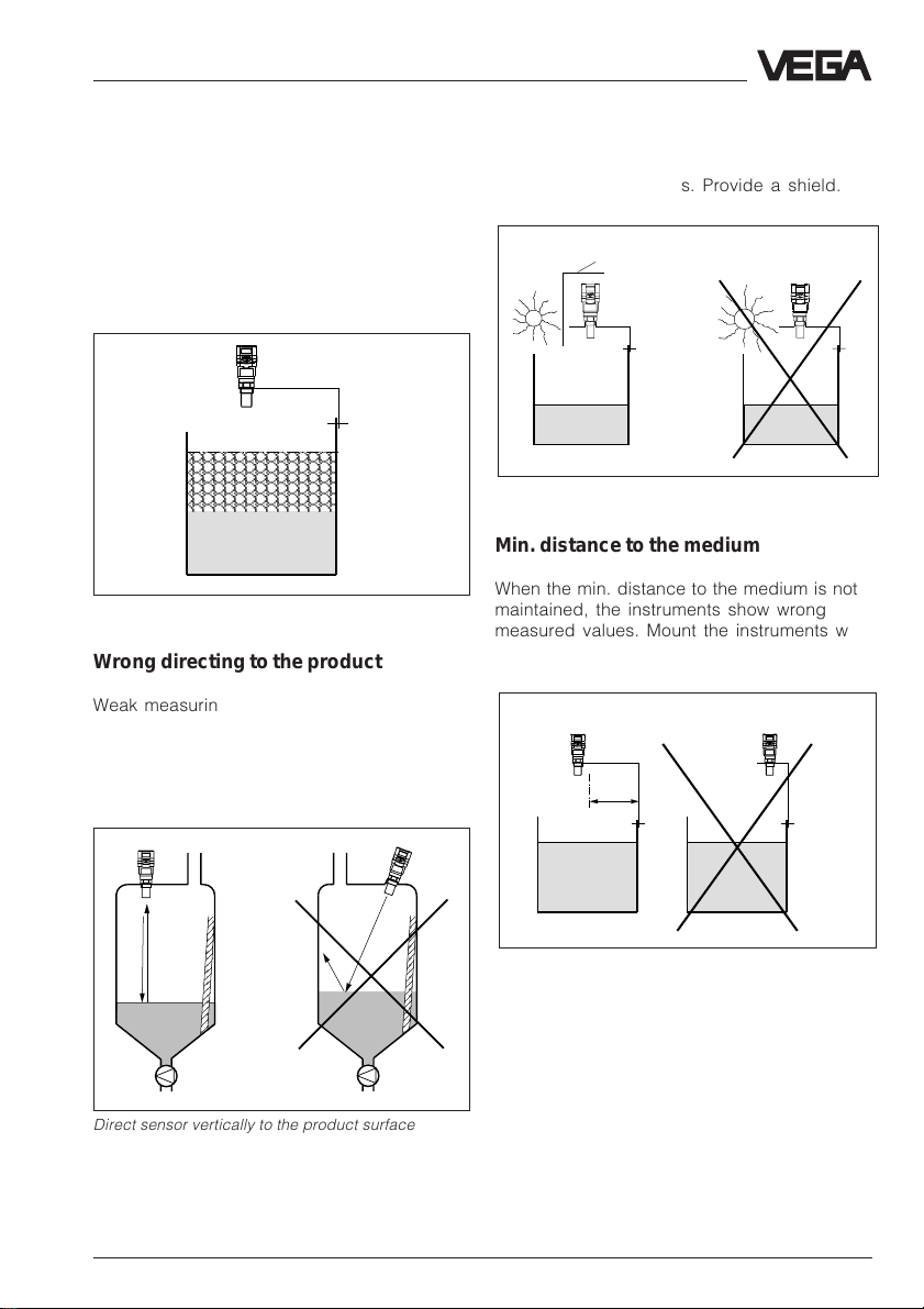
4.7 Installation error
Foam generation
Strong foam on the product can cause faulty
measurements. Provide measures to avoid
foam, measure in a bypass pipe or use another meas. principle, e.g. capacitive electrodes or hydrostatic pressure transmitters.
;;;;;;;;;;;;;
;;;;;;;;;;;;;
;;;;;;;;;;;;;
;;;;;;;;;;;;;
Foam generation
Wrong directing to the product
Weak measuring signals are caused if the
sensor is not directed to the product surface.
Direct the sensor axis vertically to the product surface to achieve optimum measuring
results.
Strong heat fluctuations
Strong heat fluctuations, e.g. due to the sun
cause measuring errors. Provide a shield.
Shield
Strong heat fluctuations
Min. distance to the medium
When the min. distance to the medium is not
maintained, the instruments show wrong
measured values. Mount the instruments with
the required min. distance.
Correct Wrong
Sensor too close to the vessel wall
Direct sensor vertically to the product surface
VEGASON 51K … 53K 33
Page 34
Mounting and installation
Sensor too close to the vessel wall
if the sensor is mounted too close to the vessel wall (dimension A in diagram) strong false
echoes can be caused. Build-up, rivets,
screws and weld joints superimpose their
echoes on the product echo or useful echo.
Please ensure the sufficient distance of the
sensor to the vessel wall depending on the
maximum measuring distance (dimension B
in diagram). In case of good reflection conditions (liquids, no vessel installation) we recommend the provision of the sensor distance
according to diagram curve 1. At a max.
meas. distance of, for example 10 m the
distance of the transducer, according to
curve 1, should be approx. 1 m. In case of
solids with bad reflection conditions provide
a distance to the vessel wall according to
diagram curve 2. With very bad meas. conditions it could be necessary to increase the
distance to the vessel wall or to gate out the
false echoes additionally by a false echo
storage and thereby adapt the sensor more
precisely to the environment.
Distance of the
transducer to the
vessel wall
Parabolic effects on dished boiler head
or basket arch vessels
Round or parabolic tank tops act like a parabolic mirror for the signals. If the sensor is
placed to the focus of such a parabolic tank
top the sensor receives amplified false echoes. The optimum mounting is generally in the
range of half the vessel radius from the centre.
Correct
> 60 mm
~ 1/
2
vessel
radius
Wrong
Curve 1 (liquids)
Curve 2 (solids)
Mounting on a vessel with parabolic tank top
Max. meas.
distance
34 VEGASON 51K … 53K
Wrong
Page 35
Mounting and installation
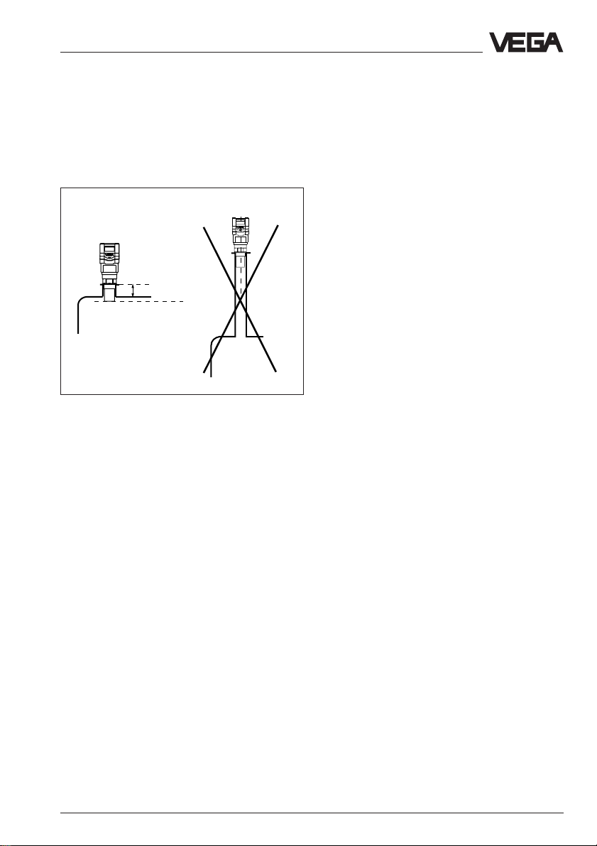
Socket piece too long
When mounting the sensor in a socket piece
which is too long, strong false echoes are
caused, aggravating the measurement.
Please ensure that the transducer protrudes
at least 30 mm out of the socket piece.
Wrong
Correct
> 60 mm
Reference plane
Correct and wrong length of socket piece
VEGASON 51K … 53K 35
Page 36

5 Electrical connection
Electrical connection
5.1 Connection and connection cable
Safety information
Ensure that the instrument is unpressurised
before you start work. Always switch off the
power supply before you carry out clamping
work on the ultrasonic sensors. Protect yourself and the instruments, especially when
using sensors which do not operarate with
low voltage.
Skilled staff
Instruments which are not operated with
protective low voltage or DC voltage must
only be connected by skilled staff.
Connection
A standard two or four-wire cable (sensors
with separate supply) with max. 2,5 mm2 can
be used as connection. Very often the "electromagnetic pollution“ by electronic actuators,
energy lines and transmitting stations is so
considerable that the two-wire line or fourwire line should be screened.
We recommend the use of screening. This
screening prevents future interferences. Only
earth the cable screens on both ends (on the
sensor and on the processing system) when
you have determined, by measurement, that
no or only lowest earth compensating currents flow via the screens. Use a very low
impedance earth connection (foundation,
plate or mains earth).
Ex-protection
If an instrument is used in hazardous areas,
the necessary regulations, conformity and
type approvals for systems in Ex-areas must
be noted (e.g. DIN 0165).
Intrinsically safe circuits with more than one
active instrument (instrument delivering
electrical energy) must not be connected.
Please note the special installation conditions
(DIN 0165).
Connection cable
Note that the connection cables are specified
for the expected operating temperatures in
your systems. The cable must have an outer
diameter of 5 … 9 mm to ensure the seal effect
of the cable entry. Cables for intrinsically safe
circuits must be marked blue and must not be
used for other circuits.
Earth conductor terminal
On VEGASON 51/52 sensors the earth conductor terminal is galvanically isolated. The
sensors are shockproof. On the VEGASON
53 sensor the earth conductor terminal is
galvanically connected to the metal transducer diaphragm.
36 VEGASON 51K … 53K
Page 37

Electrical connection
5.2 Connection of the sensor
After having mounted the sensor in the meas.
position according to the instructions in chapter 4 "Mounting and installation“, loosen the
closing screw on the top of the sensor. The
sensor cover with the optional indication
display can then be opened. Unscrew the
compression screw and shift the screw over
the approx. 10 cm dismantled connection
cable. The compression screw of the cable
entry is protected with a safety lock-in position against automatic loosening.
Supply voltage
4 … 20 mA (passive)
+
-
1)
To the indicating instrument in the
sensor cover or to the external indicating instrument VEGADIS 50
Now loop the cable through the cable entry
into the sensor. Screw the compression
screw on the cable entry and clamp the dismantled wires of the cable to the appropriate
terminal positions.
The terminals operate without terminal screw.
Press the white opening buckets with a small
screwdriver and insert the copper core of the
connection line into the terminal opening.
Check the position of the lines in the terminal
position by slightly pulling on the connection
lines.
Supply voltage
+
-
4 … 20 mA (active)
+
-
2)
Terminals
(max. 2,5 mm
12 C 567843
12 C 5678
Commu-
+-
nication
4...20 mA
+
-
Tank 1
m (d)
12.345
Tw o-wire technology
Display
ESC
OK
wire cross-section)
Sockets for connection of
the HART®-handheld or
the VEGACONNECT
pluggable
adjustment
module
MINICOM
(loop powered)
1)
4 … 20 mA passive means that the sensor takes a
current of 4 … 20 mA (consumer), depending on
the level.
2
12 C 567843
12 C 567843
Commu-
(+) (-)
L1 N
Tank 1
m (d)
12.345
nication
-
+ -
4...20 mA
+
Display
ESC
OK
Four-wire technology
(separate supply)
2)
4 … 20 mA active means that the sensor provides
a current of 4 … 20 mA (current source),
depending on the level.
Opening
buckets
VEGASON 51K … 53K 37
Page 38

Electrical connection
5.3 Connection of the external indicating instrument VEGADIS 50
Loosen the 4 screws of the housing cover on
VEGADIS 50.
You can facilitate the connection procedure
by fastening the housing cover during connection with one screw on the right of the
housing (figure).
OUTPUT
(to sensor)
3
2
1
4
5
8
6
7
DISPLAY
(in the cover of
the indicating
instrument)
VEGADIS 50
Adjustment
module
Tank 1
m (d)
12.345
+
ESC
-
OK
Screws
Voltage
supply
-
+
4 … 20 mA
active
12 C 567843
Commu-
(+) (-)
L1 N
Tank 1
m (d)
12.345
nication
+-
4...20 mA
+
-
Four-wire sensor
(separate supply)
4 … 20 mA
passive
+
-
to VEGADIS 50
12 C 567843
12 C 5678
Commu-
+-
Display
ESC
OK
4...20 mA
Tank 1
m (d)
12.345
nication
Display
+
ESC
-
OK
Tw o-wire sensor
(loop powered)
38 VEGASON 51K … 53K
Page 39

Set-up
6 Set-up
6.1 Adjustment structure
Series 50 ultrasonic sensors can be adjusted
with
- PC (adjustment program VVO)
- with the detachable adjustment module
MINICOM
- with the HART®-handheld.
The adjustment must only be carried out with
one adjustment medium. If, for example you
try the parameter adjustment with the
MINICOM and the HART®-handheld, the
adjustment will not be successful.
Adjustment program VVO
With the adjustment program VVO
Visual Operating System) on the PC you can
adjust the ultrasonic sensors very comfortably. The PC communicates via the interface
adapter VEGACONNECT 2 with the sensor. A
digital adjustment signal is therefore superimposed on the signal and supply line. The
adjustment can be carried out directly on the
sensor or on any individual position of the
signal line.
Adjustment module MINICOM
With the adjustment module MINICOM you
adjust in the sensor or in the external indicating instrument VEGADIS 50. The adjustment
module enables via the text display with 6key field the adjustment in the same functions
volume as with the adjustment program VVO.
(VEGA
6.2 Adjustment with PC
The instructions for the adjustment with the
PC and the adjustment program VVO can be
found in the manual "VEGA Visual Operating
(VVO)" which is supplied with the latest adjustment software.
Beside the adjustment of ultrasonic sensors,
the manual "VEGA Visual Operating (VVO)"
also describes the setup of all other VEGA
sensors with the PC.
PC on the sensor
For connection of the PC to the sensor you
need the interface adapter VEGACONNECT
2. Insert VEGACONNECT 2 into the
CONNECT-socket provided in the sensor.
PC on the signal line
Connect the two-wire line of VEGACONNECT
2 to the signal or supply line of the sensor.
When the resistors of the systems (DCS,
current source etc.,) connected to the signal/
supply line are less than 250 Ω, a resistor of
250 … 350 Ω must be connected to the signal/supply line during adjustment. The digital signals modulated to the signal line would
be considerably damped via the small system resistors or "shortcircuited" which means
that the communication with the PC would be
interfered with.
HART®-handheld
VEGASON 50 K ultrasonic sensors, like other
HART®-protocol capable instruments, can be
adjusted with the HART®-handheld. A manufacturer specific DDD (Data-Device-Description) is not required. The ultrasonic sensors
are adjusted with the HART®-standard
menus. All main functions are, therefore,
accessible.
Some functions which are rarely used such
as, for example the scaling of the A/D-converter for the signal output, or the adjustment
with medium, are not possible or are blocked
by the HART®-handheld. These functions
must be carried out with the PC or the
MINICOM.
VEGASON 51K … 53K 39
Page 40
Set-up
6.3 Adjustment with the adjustment module MINICOM
As with the PC, you can also adjust the sensor with the small detachable adjustment
module MINICOM. The adjustment module is
thereby plugged into the sensor or into the
external indicating instrument (optional).
ESC
+
-
Tank 1
m (d)
OK
12.345
2
4 ... 20 mA
ESC
+
-
Tank 1
m (d)
OK
12.345
4
For the adjustment with the adjustment module all sensor versions (adjustment options)
as with the PC and the adjustment program
VVO are available. The adjustment with
MINICOM, however, is different.
Error codes:
E Hardware failure, electronics defect
E013 No valid measured value
- Sensor in the feeding phase
- Loss of the useful echo
E017 Adjustment span too small
E036 Sensor program not operating
- Sensor must have a new program-
ming (service)
- Fault signal also appears during
programming
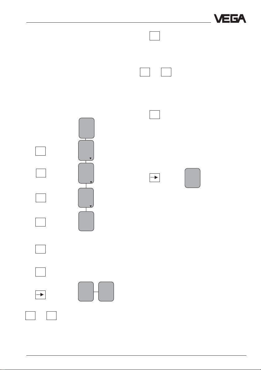
Adjustment steps
On pages 56 and 57 you can find the complete menu plan of the adjustment module
MINICOM.
Set-up the sensor in the numbered sequence:
1. Adjustment
2. Conditioning
3. Outputs
4. Operating range
5. Meas. conditions
6. Measurement in gases only necessary
when measuring gas compositions other
than air.
7. False echo memory (only required when
meas. errors occur during operation).
8. Indication of the useful and noise level
Short explanations to the set-up steps 1 … 8
follow:
You carry out all adjustment steps with the 6
keys of the adjustment module. A small dis-
1. Adjustment
play shows you, apart from the measured
value, a short message on the menu point or
on the figure of a menu adjustment.
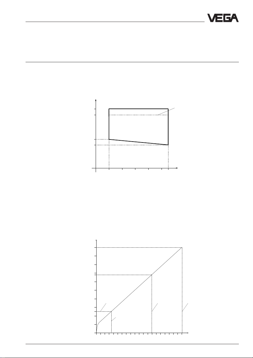
The information volume of the small display
Max.
100 % (1,270 m) corresp. to
1200 l
however cannot be compared with that of the
adjustment program VVO, but you will soon
get used to it and will be able to carry out
your adjustments quickly and directly with
Span (4,58 m)
the small MINICOM.
Min.
40 VEGASON 51K … 53K
0 % (5,850 m) corresp. to
45 l
Page 41
Set-up
Under the menu point "
Adjustment
“ you inform the sensor with which meas. range it
should operate.
You can carry out the adjustment without and
with medium. Generally you will carry out the
adjustment without medium as you can then
adjust without filling cycle.
Adjustment without medium
(adjustment independent of the actual level)
Key Display
Sensor
m(d)
4.700
Parameter
OK
OK
OK
OK
+
The distance indication flashes
and you can choose "feet“ and
adjust
ment
Adjust
ment
w.out
medium
Adjust
ment
in
m(d)
(Min. adjustment)
"m“.
OK
+ –
or
Confirm the adjustment with
"OK“.
m(d)
0.0%
bei
m (d)
XX.XXX
Adjust
ment
in
With "+“ and "–“ you adjust the
percentage value for the min.
value or the lower level l (example 0,0 %).
OK
The adjusted percentage
value is written in the sensor
and the distance corresponding to the percentage value
flashes.
+ –
or
With the "+“ or "–“-key you can
co-ordinate a product distance (example 5,85 m) to the
previously adjusted percentage value. When you do not
know the distance, you have
to sound.
OK
The adjusted product distance is written in the sensor
and the indication stops flashing.
You have thereby adjusted the lower product
distance as well as the percentage filling
value corresponding to the lower product
distance.
100.0%
at
m (d)
XX.XXX
(Max-adjustment)
The max. adjustment (upper product distance) is made in the same way (example:
100 % and 1,270 m).
Note:
The difference between the adjustment values of the lower product distance and the
upper product distance should be as big as
possible, preferably at 0 % and 100 %. If the
values are very close together, e.g. lower
product distance at 40 % (3,102 m) and
upper product distance at 45 % (3,331 m),
the measurement will be inaccurate.
A level characteristic is generated from the
two points. Even with smallest deviations
between actual product distance and adjusted product distance, the slope of the
characteristics will be considerably influenced. Thereby small failures multiply with
the adjustment when the adjustment points
are too close together to more considerable
errors at the output of the 100 %-value or the
0 %-value.
VEGASON 51K … 53K 41
Page 42

Set-up
Adjustment with medium
with
medium
Max.
Min.
adjust
adjust
at %
at %
XXX.X
XXX.X
Fill the vessel, for example to 10 % and enter
10 % in the menu "
Min. adjust
“ with the "+“
and "–“ keys. Then fill the vessel, e.g. to 80 %
or 100 % and enter 80 % or 100 % in the
menu "
Max. adjust
“ with the "+“ and "–“ keys.
2. Conditioning
Signal
condit
ioning
Scal
ing
0 %
100 %
Deci-
prop.
corres
corres
ponds
XXXX
mal
point
888.8
Signal conditioning
ponds
XXXX
Under the menu point "
you choose the product distance at 0 % and
at 100 % filling. Then you enter the parameter
and the physical unit as well as the decimal
point.
Enter in the menu window "
0 % corresponds
the value of the 0 %-filling. In the example of
the adjustment with the PC and the adjustment software VVO this would be 45 for 45 l.
Unit
to
Mass
Kg
“
With the "—>“ key you change to the 100 %
menu. Enter here the figure of your parameter corresponding to a 100 %-filling. In the
example 1200 for 1200 l.
• Confirm with "OK“.
If necessary choose a decimal point. However note that only max. 4 digits can be displayed. In the menu "
Prop. to
“ you choose
the parameter (mass, volume, distance…)
and in the menu "
Unit
“ the physical unit (kg, l,
ft3, gal, m3 …).
Linearisation:
Adjust
ment
Signal
condit
ioning
Scal
ing
Lin.
curve
Linear
Integr
ation
time
0 s
A linear dependence between percentage
value of the product distance and the percentage value of the filling volume is
preadjusted. With the menu "Lin.curve“ you
can choose between linear, spherical tank
and cylindrical tank. The adjustment of one's
own linearisation curve is only possible with
the PC and the adjustment program VVO.
3. Outputs
Under the menu "
“
for example the current output should be
inverted or which parameter should be provided by the sensor display.
Outputs
“ you determine if,
• Confirm with "OK“.
42 VEGASON 51K … 53K
Page 43

Set-up
4. Operating range
Without special adjustment, the operating
range corresponds to the measuring range.
The measuring range has already been adjusted with the min./max. adjustment. Generally it is useful to choose a slightly bigger
(approx. 5 %) operating range than the
measuring range.
Example:
Set min./max. adjustment to: 0,300 … 5,850
m; operating range to approx. 0,250 … 6,000
m.
5. Meas. conditions
(see menu plan no. 5)
6. Measurement in gases
Adjustment is only necessary when the
measurement is made in gases (Co2, He,
etc.) deviating from air. In case of measurement in gases sound the distance of the
sensor to the product surface and enter in
the menu point "Measurement in gases“. The
sensor can then consider the modified sound
velocity in gases as opposed to air and provide correct levels.
7. False echo storage
A false echo storage is always useful when
false echo sources such as struts must be
reduced. With the creating of a false echo
storage, you authorise the sensor electronics
to note the false echoes and save them in an
internal database. The sensor electronics
treat these (false) echoes differently from the
useful echo and gates them out.
8. Useful and noise level
In the menu
you get important information on the signal
quality of the level echo. The higher the
"S-N“-value, the more reliable the measurement (menu plan MINICOM).
Ampl.: Means amplitude of the level echo in
S-N: Means Signal-Noise, i.e. the useful
The higher the "S-N“-value (distance of the
amplitude useful level to noise level), the
better the measurement:
> 50 dB Measurement excellent
40 … 50 dB Measurement very good
20 … 40 dB Measurement good
10 … 20 dB Measurement satisfactory
5 … 10 dB Measurement sufficient
< 5 dB Measurement poor
Example:
Ampl. = 68 dB
S-N = 53 dB
68 dB – 53 dB = 15 dB
53 dB signal distance means very good
reliability.
This means that the noise level is only
68 dB – 53 dB = 15 dB.
Ampl.:
XX dB
S-N:
XX
dB
dB (useful level)
level minus the level of the background noise
VEGASON 51K … 53K 43
Page 44

Menu plan of the adjustment module MINICOM
Set-up
Sensor
m(d)
4.700
Param
eter
adjust
ment
Sensor
optimi
sation
Sensor
Tag
Sensor
Meas.
enviro
nement
Operating
range
Begin
m (d)
0.50
SON 52
K
1.00
4.
When switching on, the sensor type and the
software version are displayed for a few seconds.
End
6.00
m (d)
Meas.
condit
ions
Condit
ion
liquid
5.
Fast
change
No
Measur
ing in
tube
Meas.
dist.
m (d)
4.700
Correction
Now!
Agitat
ed sur
face
No
OK?
6.
Foaming
prod.
No
High
dust
level
No
Large
angle
repose
No
Measur
ing in
tube
No
Vielfachechos
No
1. 2. 3.
Adjust
ment
w.out
medium
Adjust
ment
in
m(d)
with
medium
Min.
adjust
at %
XXX.X
0.0 %
at
m (d)
XX.XXX
Max.
adjust
at %
XXX.X
100.0%
at
m (d)
XX.XXX
Auswertung
Scaling
0 %
corres
ponds
XXXX
Lin.
curve
Linear
100 %
corres
ponds
XXXX
Integr
ation
time
Dezimal
point
888.8
0 s
prop.
to
Mass
Unit
Kg
Outputs
mAoutput
mAoutput
4-20mA
Failure
mode
22mA
Sensor
displ.
prop.
to
Distance
44 VEGASON 51K … 53K
Page 45

Set-up
With these keys you move in
the menu field to the left, right,
top and bottom
ESC
7. 8.
OK?
OK?
Distance
m (d)
4.700
Update
Meas.
dist.
m (d)
X.XX
Update
Now!
OK?
Learning!
Simulation:Simulation:
Simulation:
Simulation:Simulation:
One hour after the last simulation
adjustment the sensor returns automatically to normal operating condition.
Error codes:Error codes:
Error codes:
Error codes:Error codes:
E Hardware failure
E013 No va li d mea sure d val ue
E017 Adju st ment span too small
%
E036 No operating sensor program
False
echo
memory
Create
new
Meas.
dist.
m (d)
X.XX
Create
new
Now!
Learning!
Simulation
Simulation
Now!
Simulation
XXX.X
Add'l
functions
Ampl.:
XX dB
S-N:
XX
Delete
Delete
Now!
OK?
Deleting!
dB
Info
Sensor
Tag
Sensor
Reset
to de
fault
Reset
Now!
OK?
Reset
runs!
Sensor
type
SON52
K
- Sensor in feeding phase
- Loss of the useful echo
- Sensor must have a new
programming (service)
- Fault signal also appears during
programming
Language
English
Serial
number
1094
0213
Meas.
unit
Softw.
Vers.
0.40
Distance
m
X,XX
Heavy
dust
No
Fast
change
Yes
m (d)
Softw.
date
15.09.
1997
OK
max.
range
m (d)
7.000
Menu points in bold print provide
sensor and measured value
information and cannot be modified
in this position.
Light grey menu fields are only
displayed if required (depending on
the adjustments in other menus).
White menu points can be modified with the "+“ or "–“-key and
saved with the "OK“-key .
Distance
m (d)
4.700
Ampl.:
XX dB
S-N:
XX
dB
VEGASON 51K … 53K 45
Page 46

6.4 Adjustment with the HART®-handheld
With each HART®-handheld you can set-up
the VEGASON series 50K ultrasonic sensors
like all other HART®-capable sensors. A special DDD (Data Device Description) is not
necessary.
Just connect the HART®-handheld to the
signal line, after having connected the sensor
to power supply.
+
-
Set-up
Ri < 250 Ω
Note:
If the resistor of the power supply is less than
250 Ohm, a resistor must be looped into the
signal/connection line during adjustment.
250 Ω
Connection to a VEGA-signal conditioning instrument
When you operate a HART®-capable sensor
on a VEGA-signal conditioning instrument,
you have to connect the sensor via a resistor
according to the following table during the
HART®-adjustment, to reach together with the
inner resistor of the instruments the value of
250 Ohm required for the HART®-instrument.
The digital adjustment and communication
signals would be short-circuited via too small
resistors of the supply current source of the
processing system which means that the
sensor communication could not be ensured.
+
-
Ri < 250 Ω
VEGA-signal conditioning instr. Rx
VEGAMET 513, 514, 515, 602 50 … 100 Ohm
VEGAMET 614 no additional
VEGADIS 371 res istor
required
VEGAMET 601 200 … 250 Ohm
VEGASEL 643 150 … 200 Ohm
VEGAMET 513 S4, 514 S4
515 S4, VEGALOG EA-card 100 … 150 Ohm
46 VEGASON 51K … 53K
Page 47

Set-up
VEGALOG VEGAMET
Rx
The most important adjustment steps
On the following pages you see a menu plan
for the HART®-handheld in conjunction with
VEGASON 51K … 53K sensors. The most
important adjustment steps are marked in the
menu plan with the letters A … E. When entering parameters first of all the key "
must be pressed. The adjustment is thereby
saved in the handheld, but not in the sensor
itself.
Generic: SENSOR
PV URV
5.850 m
0.300 m
HELP DEL ESC ENTER
After having pressed "
ENTER
(here in the example for the min.-adjustment).
Generic: SENSOR
1 PV LRV 5.850 m
2 PV URV 0.300 m
HELP SEND HOME
After pressing "
SEND
“, a warning is displayed, which informs you that you are about
to modify the configuration and for that,
safety reasons, you should switch your system over to manual operation.
ENTER
4.2
(5.2)
“, press "
“
SEND
Generic: SENSOR
WARN-Loop should be
removed from
automatic control
ABORT OK
Press "OK“ and the adjustment will now be
transferred to the sensor. After a short time
you are asked to switch you system over
from manual to automatic operation. Confirm
with "OK“.
Generic: SENSOR
NOTE- Loop may be returned to automatic control
“
OK
You see the actual carried out adjustment.
Generic: SENSOR
1 PV LRV 5.850 m
2 PV URV 0.300 m
HELP HOME
VEGASON 51K … 53K 47
Page 48
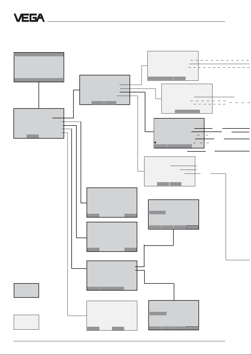
HART®-menu plan VEGASON 51K… 53K
Set-up
Switch on:
Hart Communicator
Self Test
in Progress
Firmware Rev: F2.2
Module Rev: 3.6
01992-96 FRSI
after approx.
20 s
Generic: SENSOR
Online(Generic)
1 Device setup
2 PV 2.281 m
3 PV AO 15.059 mA
4 PV LRV 7.000 m
5 PV URV 0.000 m
SAVE
Generic: SENSOR
Device setup
1 Process variables
2 Diag/Service
3 Basic setup
4 Detailed setup
5 Review
SAVE HOME
Generic: SENSOR
PV
2.281 m
HELP EXIT
Generic: SENSOR
AA1
15.264 mA
1
2
3
Generic: SENSOR
Process variables
1 Snsr 2.281 m
2 AI % rnge 69,140 %
3 AO 1 15.059 mA
HELP SAVE HOME
Generic: SENSOR
Diag/Service
1 T est device
2 Loop test
3 Calibration
4 D/A trim
SAVE HOME
Generic: SENSOR
Basic setup
1Tag
2 PV Unit
3 Range values
4 Device information
5 PV xfer fnctn
HELP SAVE HOME
6 PV Damp
Generic: SENSOR
Detailed setup
1 Sensors
2 Signal condition
3 Output condition
4 Device information
SAVE HOME
Generic: SENSOR
PV LRV
7.000 m
5.850 m
HE LP DE L ESC ENTER
1.1
1.4
not necessary
}
4.1
(5.1)
1.2
1.3
not necessary
linear
1.3.6
1.4.3
AA
A
AA
(max.
meas.
distance)
1.3.1
1.2.2
}
1.3.2
1.3.4
HELP EXIT
4
5
Generic: SENSOR
PV URV
0.000 m
0.300 m
HELP DEL ESC ENTER
4.2
(5.2)
BB
B
BB
(min.
meas.
distance)
Important and
necessary menu
windows
Less important
menu windows
Generic: SENSOR
1 PV LRV 7.000 m
2 PV URV 0.000 m
HELP HOME
Generic: SENSOR
1 PV LRV 7.000 m
2 PV URV 0.000 m
HELP HOME
Continue as under figure 4
48 VEGASON 51K … 53K
Page 49
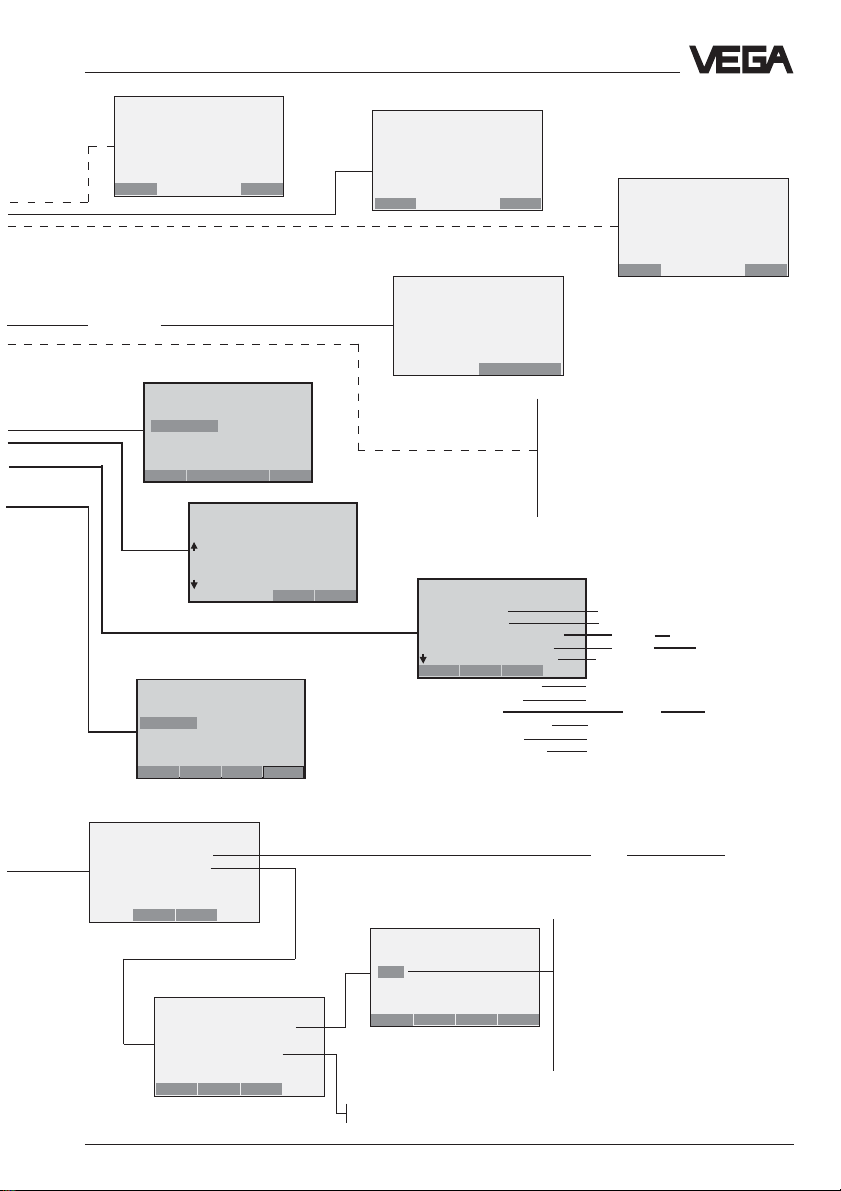
Set-up
Generic: SENSOR
PV
2.281 m
HELP EXIT
1.1.1
Generic: SENSOR
PV % rnge
70.390 %
HELP EXIT
1.1.2
Generic: SENSOR
A01
15.264 mA
1.1.3
Switch off
control
Generic: SENSOR
Tag
EE
E
EE
SENSOR
SENSOR
HELP DEL ESC ENTER
CC
C
CC
Generic: SENSOR
Device information
1 Distributor
2 Model
3Dev id
4Tag
5 Date 01/01/97
HELP SAVE HOME
Generic: SENSOR
Output condition
1 Analog output
2 HART output
Generic: SENSOR
PV Snsr unit
m
m
bbl
in
cm
ESC ENTER
1.4.3
1.3.1
1.3.6
1.3.2
Generic: SENSOR
Choose analog output
level
14mA
2 20mA
3 Other
4End
ABORT ENTE R
Generic: SENSOR
Tag
Sensor
Sensor
HE L P DE L ESC ENTER
6 Write protect None
7 Descriptor
8 Message
9 PV Snsr s/n
Final asmbly num
Revision #'s
1.2.2
The following menu windows are not
supported by the sensor. Saving of adjustments carried out here is not possible.
The adjustment of actual "empty“ or "full“
measured values should be carried out in
the menu window 4.1 and 4.2. Enter there
the meas. distance with empty vessel as
zero and the meas. distance with full
vessel as end.
HELP EXIT
Individual current values for test
purposes (measured value simulation).
See also menu window 1.4.3.1.
on the next page
1.3.4
1.3.4.1
1.3.4.2
1.3.4.5
1.3.4.6
1.3.4.7
1.3.4.9
1.3.4.10
1.3.4.11
1.4.3.1
1.3.4.3
1.3.4.4
1.3.4.8
Sensor serial number
like menu 1.3.1
DD
D
DD
see
next
page
see
next
page
SAV E HOME
Generic: SENSOR
HART output
1 Poll addr 0
2 Num req preams 0
3 Burst mode
4 Burst option
HELP SAVE HOME
VEGASON 51K … 53K 49
1.4.3.2
Generic: SENSOR
Poll addr
0
0
HELP DEL ESC ENTER
Off: Sensor signals measured values only on request
On: Sensor signals measured values unrequested
1.4.3.2
Multidrop:
The sensor also provides te 4 … 20 mA
signal, as well as a digital (HART®)-level
signal :
• If the poll address is zero, the sensor
takes a level dependent 4…20 mAcurrent and delivers a digital (HART®)level signal.
• If the poll address is 1…15, the sensor
still delivers a digital (HART®)-level
signal, however the sensor current is
frozen to 4 mA. The 4…20 mA-signal is
then no longer available.
Page 50
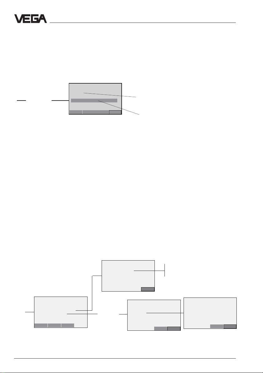
Continuation HART®-menu plan – VEGASON 51K…53K
DD
D
from 1.3.4
DD
Generic: SENSOR
Message
..SOL
..FEN04.58M
1.3.4.8
Initialisation word
(enter at last)
Set-up
from
1.4.3.
HE L P DE L ESC ENTER
Generic: SENSOR
Analogue output
1 A01 13,467mA
2 A0 Alrm typ
3 Loop test
4 D/A trim
5 Scaled D/A trim
HELP SAVE HOME
newly entered and initialisation word to enquire with
ENTER and SEND
Available initialisation words:Available initialisation words:
Available initialisation words:
Available initialisation words:Available initialisation words:
..SOL Meas. condition solid
..LIQ Meas. condition liquid
..FED Delete false echo memory
..FEN04.58M False echo e.g. at 4.58 m create new
..FEN48.67FT False echo e.g. at 48.67 ft create new
..FEU03.68M Extend false echo memory:
..FEU36.05FT add a new false echo to the false echo memory at 36.05 ft
1.4.3.1
Warning:
Switch off
control!
add a new false echo to the false echo memory at 3.68 m
Note:
After the adjustment of the initialisation word, press
"ENTER“ and then "SEND“.
Confirm the message to change over to manual
operation with "OK“ and the message to switch over
to automatic operation again with "OK“.
Only then is the adjustment written in the sensor and
effective.
Generic: SENSOR
A0 Alrm typ
High
1.4.3.1.2
Low: Not selectable r (3,6 mA)
High: In case of failure current output
Exit
Generic: SENSOR
Choose analogue output
level
14 mA
2 20 mA
3 Other
4End
1.4.3.1.3
Abort Enter
goes to < 21,5 mA
Generic: SENSOR
Fld dev output is
fixed at 4.000 mA
1.4.3.1.3.1
ABORTOK
50 VEGASON 51K … 53K
Page 51
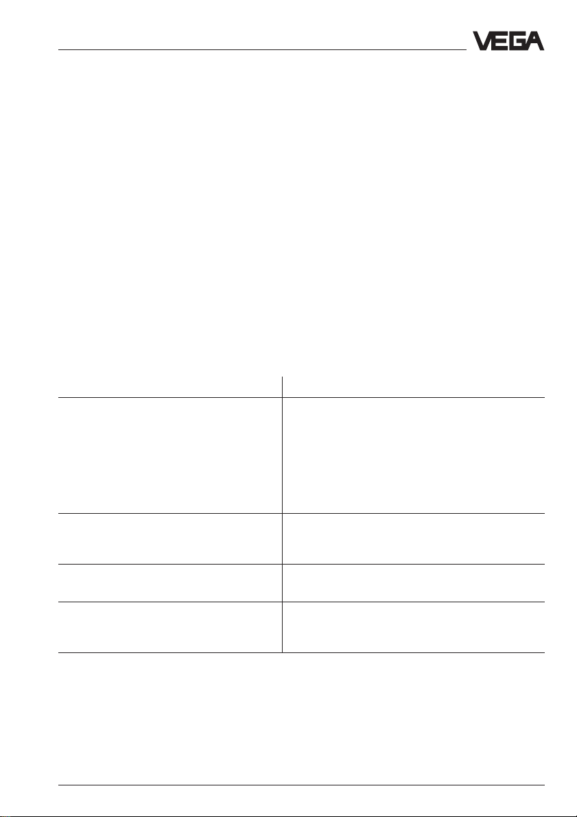
Diagnose
7 Diagnosis
7.1 Simulation
To simulate a certain filling, you can call up
the function "Simulation" on the adjustment
module MINICOM, in the software program
VVO or in the HART® handheld.
With this function, you simulate a and hence a
real sensor current vessel filling level. Please
note that connected instruments, such as
e.g. a PLC, react according to their adjustments and will probably activate alarms or
system functions.
7.2 Error codes
Error codes Corrective measure
E013 No valid measured value Message is displayed during the warm-up
- Sensor in the warm-up phase phase
- Loss of the useful echo If the message remains, a false echo storage
(menu "Sensor optimisation") must be carried out
with the adjustment modul MINICOM or better
with the PC and VVO.
If the meassage is still displayed, you have to
carry out a readjustment.
E017 Adjustment span too small Carry out a readjustment.
E036 Sensor software does not run Sensor requires a software (service).
E040 Hardware failure/Electronics defec- Check all connection cables.
tive Transducer defective.
VEGASON 51K … 53K 51
Make sure that the difference between
min. and max. adjustment is at least 10 mm .
Message appears during a software update.
Contact our service department.
Page 52

VEGA Grieshaber KG
Am Hohenstein 113
D-77761 Schiltach
Telefon (07836) 50-0
Fax (07836) 50-201
E-Mail info@de.vega.com
www.vega.com
ISO 9001
The statements on types, application, use and operating conditions of
the sensors and processing systems correspond to the actual
knowledge at the date of printing.
Technical data subject to alteration.
21758-EN-020313
 Loading...