

Page 1
Operating Instruction
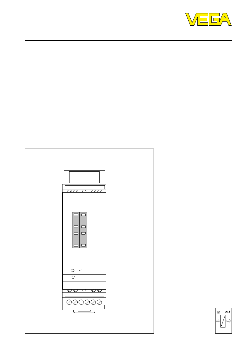
VEGASEL 643
12 43
Level and Pressure
–
–
max.
5
6
++
–
–
min.
5
3
++
on
VEGASEL 643
56 78
9 1011121314
out
in
Page 2

Contents
Safety information ........................................................................................ 2
1 Product description
1.1 Function and configuration ................................................................. 3
1.2 Approvals ............................................................................................ 3
1.3 Types and versions ............................................................................. 4
1.4 Technical data and dimensions .......................................................... 4
2 Mounting and installation instructions .......................................... 7
3 Electrical connection
3.1 Wiring instruction ................................................................................ 8
3.2 Wiring plan .......................................................................................... 8
4 Set-up
4.1 Indicating and operating elements ................................................... 10
4.2 Set-up sequence .............................................................................. 11
4.3 Switch point adjustment.................................................................... 11
Contents
5 Diagnosis
5.1 Maintenance ..................................................................................... 13
5.2 Repair ............................................................................................... 13
5.3 Failure removal ................................................................................. 13
Safety information
The described module must only be inserted and operated as described in this operating instruction. Please
note that other action can cause damage for which VEGA
does not take responsibility.
2 VEGASEL 643
Page 3
Product description
1 Product description
1.1 Function and configuration
VEGASEL 643 auxiliary level switch is a build-in instrument with terminal socket, suitable for carrier rail
mounting (DIN 46 277). Together with a sensor or a
VEGAMET… signal conditioning instrument it is used
for level detection.
Typical applications are two-point controls, e.g. pump
controls (ON/OFF) and monitoring functions such as
overfill protection and protection against dry running of
pumps.
The auxiliary level switch is provided with two passive
inputs, a current and a voltage input as well as additionally with an active current input. Hence VEGASEL
643 can be connected for control either with a
VEGAMET… or a sensor (4 … 20 mA).
12 43
–
–
max.
5
6
++
–
–
min.
5
3
++
on
VEGASEL 643
56 78
91011121314
Sensor
(4 … 20 mA)
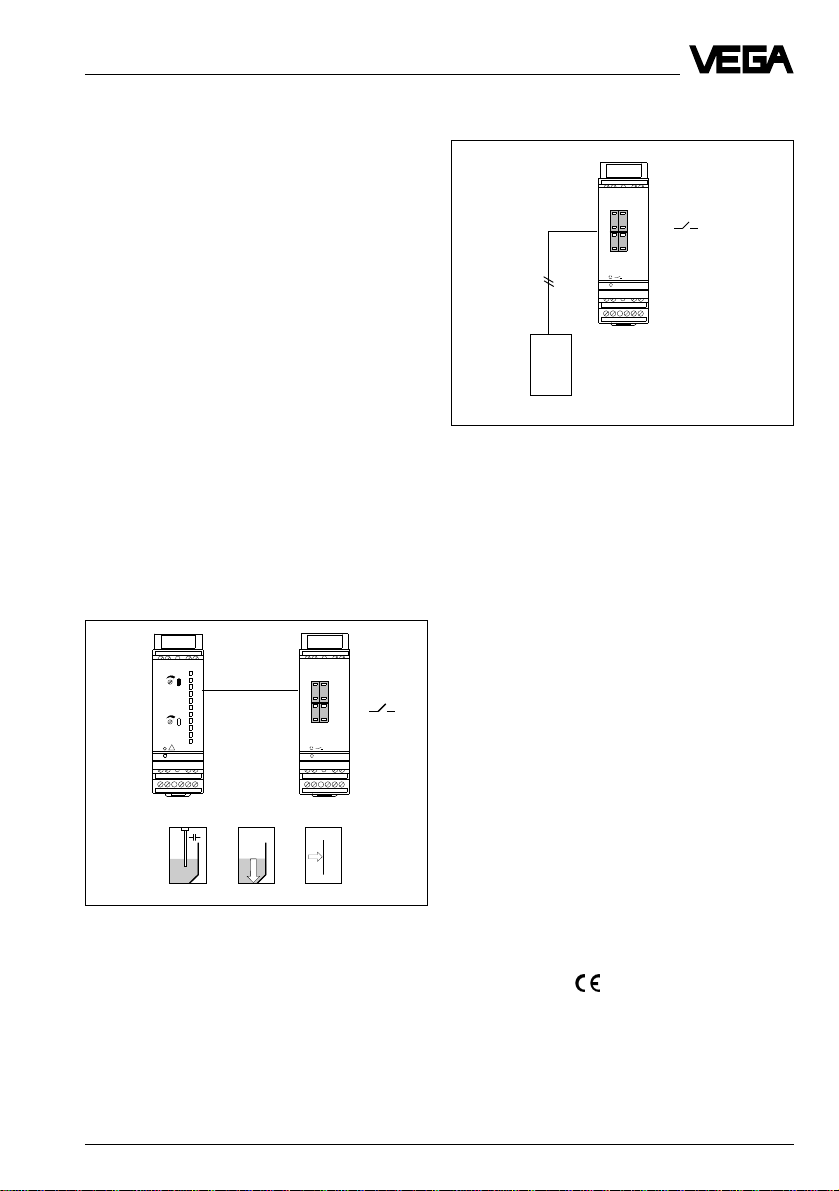
Fig. 1.2 VEGASEL 643 with sensor
Function
VEGASEL 643, controlled by a VEGAMET…
- The continuous current or voltage course of the
VEGAMET… signal processing instrument is
processed into a switching command.
12 43
100
%
0/4 … 20 mA
50
0 … 10 V
0
!
on
VEGAMET 602EX
56 78
91011121314
Fig. 1.1 VEGASEL 643 on a VEGAMET
VEGASEL 643 with a 4 … 20 mA sensor
- VEGASEL 643 auxiliary level switch powers via the
active current input the sensors and processes its
continuous 4 … 20 mA current signal into a switching command.
12 43
–
–
max.
5
6
or
++
–
–
min.
5
3
++
on
VEGASEL 643
56 78
91011121314
p
p
In both cases a relay output is available for processing.
Configuration
With a VEGASEL 643 an available measuring system,
consisting of sensor and VEGAMET signal conditioning instrument can be extended by a level detection.
Or an own measuring system can be created with a
4 … 20 mA sensor.
1.2 Approvals
If measuring systems are created according to the
following approvals, the respective legal documents
and their regulations have to be observed. These
documents are supplied with the respective measuring system.
WHG-approval, VbF-approval
VEGASEL 643 auxiliary level switch together with a
measuring system (sensor and VEGAMET) as part of
an overfill protection acc. to WHG (test certificate
applied) or acc. to the regulations for combustible
liquids (test certificate applied).
CE-conformity
see „1.4 Technical data“.
VEGASEL 643 3
Page 4
Product description
off
on
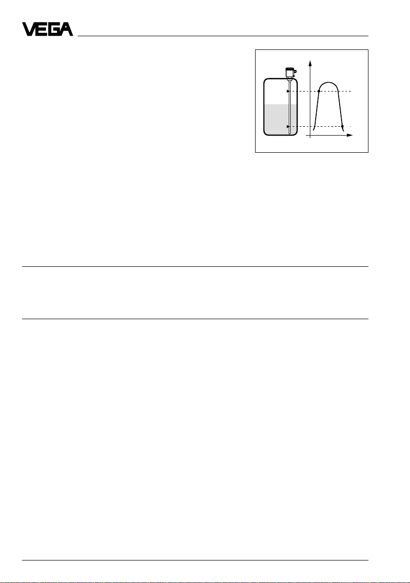
1.3 Types and versions
VEGASEL 643
Two-point auxiliary level switch with selectable mode; mode A (overfill
protection) or mode B (protection against dry running of pumps)
adjustable switching hysteresis
Inputs: - passive current input 0/4 … 20 mA
- active current input (connections of a sensor
4 … 20 mA)
- passive voltage input 0/2 … 10 V
Outputs: 1 relay (spdt)
Approvals: as part of an overfill protection acc. to WHG and
VbF
Application: level detection, overfill protection,
protection against dry running of pumps
Max.
Min.
Fig. 1.2 Two-point auxiliary level switch
VEGASEL 643
1.4 Technical data and dimensions
General data
Power supply
Operating voltage 20 … 250 V AC, 50/60 Hz
Power consumption max. 1,7 W (4,5 VA)
Fuse T 1 A, 250 V
Measuring data inputs
Input 1 1 current input
Kind of input active two-wire input analog
Range 4 … 20 mA
Application connection of sensors (4 … 20 mA)
Sensor supply voltage 16 … 24 V DC
Switching threshold adjustable via coded key
Min. hysteresis 1 %
Current limitation appr. 25 mA, permanently shortcircuit proof
Temperature error 0,05 %/10 K of range
Switch point error 0,5 % of adjusted switch point
Connection cable 2 wire (standard line)
Resistor per conductor max. 35 Ω
Interlock diode for connection of a measuring instrument
20 … 72 V DC
max. load 15 Ω
Level
Time t
Input 2 1 additional current input
Kind of input passive two-wire input analog
Range 0/4 … 20 mA
Inner resistor Ri = 50 Ω
Application direct connection to active current output of e.g.
VEGAMET 601, 602 Ex
Switching threshold adjustable via coded key
Min. hysteresis 1 %
Temperature error 0,05 %/10 K of range
Switch point error 0,5 % of adjusted switch point
4 VEGASEL 643
Page 5

Product description
Input 3 1 voltage input
Kind of input passive two-wire input analog
Range 0/2 … 10 V DC
Inner resistor Ri ≥ 100 kΩ
Application direct connection to active voltage output of
Switching threshold adjustable via coded key
Min. hysteresis 1 %
Temperature error 0,05 %/10 K of range
Switch point error 0,5 % of adjusted switch point
Connection cable 2-wire (standard line)
Resistor per conductor max. 100 Ω
Electrical connection
Screw terminal max. 1,5 mm
Electrical protective measures
Protection
- instrument IP 30
- terminal socket IP 20
Protection II
Overvoltage category II
Mechanical data
Series module instrument with terminal socket incl.
Mounting carrier rail mounting acc. to DIN 46 277, Bl. 3
Dimensions unassembled W = 36 mm, H = 118,5 mm, D = 134 mm
Weight appr. 170 g
e.g. VEGAMET 601, 602 Ex
2
transparent cover, cover of the sensor terminals,
coded pin, two connection bridges
Ambient conditions
Permissible ambient temperature -20°C … +60°C
Storage and transport temperature -40°C … +70°C
Relay output
Number 1 output
Contact 1 spdt (open 12 - 13, closed 12 - 14)
AgCdO and Au plated
Turn-on voltage min. 10 mV DC
max. 250 V AC, 60 V DC
Switching current min. 10 µA DC
max. 2 A AC, 1 A DC
Breaking capacity max. 125 VA, 54 W
Indicating elements
LED in front plate green on: operating voltage on
yellow on: relay energized
Functions
Mode overfill protection (A)
protection against dry running of pumps (B)
Adjustments of the inputs 0 … 20 mA or 4 … 20 mA
0 … 10 V or 2 … 10 V
VEGASEL 643 5
Page 6

Product description
Operating elements
Front plate 2 coded key
Laterally on top 1 DIL-switch for adjustment
Electrical separating measures
Reliable separation acc. to VDE 0106, part 1 between power supply, meas. data inputs
- limit voltage 250 V
- isolation resistance 3 kV
CE-conformity
VEGASEL signal conditioning instruments meet the protective regulations of EMVG (89/336/EWG) and NSR
(73/23/EWG). The conformity has been judged acc. to the following standards:
EMVG Emission EN 50 081 - 1
Immission EN 50 082 - 2
NSR EN 61 010
Carrier rail 35 x 7,5 or
35 x 15 acc. to EN 50 022
Transparent cover
0 … 99 %
- mode A/B (overfill protection/protection against dry
running of pumps)
- adjustment possibility of the inputs
0 … 20 mA or 4 … 20 mA
0 … 10 V or 2 … 10 V
and level relais
12 4
3
118,5
54,5
134
VEGA
56 78
9 1011121314
36
6 VEGASEL 643
Page 7

Mounting and installation instructions
2 Mounting and installation instructions
Mounting
Each series 600 signal conditioning instrument consists of a terminal socket for carrier rail mounting DIN
46 277 and a module instrument.
The supply voltage can be connected to terminals 9
and 10.
For neighbouring series 600 signal conditioning
instruments it is possible to provide and loop the
connection L1 and N directly via the supplied bridges.
The same is valid for the connection VEGAMETvoltage output 0 … 10 V to VEGASEL-voltage input
0 … 10 V /terminals 7 and 8).
Note, danger!
Never use the bridges with single instrument or at the
end of an instrument row. They may come in touch
with the operating voltage or cause a shortcircuit.
Coding
The terminal socket must be provided with pins and
the signal conditioning instrument with appropriate
gaps (mechanical coding) to avoid interchanging of
the individual signal conditioning instruments.
An instrument coding ensures that interchanging
among the signal conditioning instruments is avoided
by differently positioned coded keys.
Instrument coding
VEGASEL 643 (pin 4)
Direct connection for
voltage input 0 … 10 V
Direct connection for
supply voltage
12 4
A o
B o
C o
1 o
2 o
3 o
o
o
o
7 o
8 o
9 o
o
o
o
3
VEGA
0…10 V
N
L1
56 78
9 1011121314
VEGASEL 643 7
Page 8

3 Electrical connection
Electrical connection
3.1 Wiring instruction
The following wiring plan and the extension examples
1 and 2 are valid for standard as well as for Ex-versions of the signal conditioning instruments. Please
note the following instructions:
- the relay contact is shown in unpressurized
condition
- if strong electromagnetic interferences are expected, we recommend to use screened cable for
the signal lines
- the screening must only be earthed at one sensor
side
- in case of overvoltages we recommend the use of
VEGA-overvoltage arresters
- the connection must be made according to the
appropriate national installation standards (e.g. in
Germany according to VDE-regulations).
3.2 Wiring plan
Sensor
+
+–
10 V
78
111213 14
–
43
–
+
12
VEGASEL 643
910
L1
N
+
–
Supply voltage
active current input for connection of a sensor (4 … 20 mA)
passive current input for
connection of a signal conditioning instrument
(VEGAMET…)
passive voltage input for
connection to the voltage
output of a signal conditioning
instrument (VEGAMET…)
Relay output
8 VEGASEL 643
Page 9

Electrical connection
Extension example 1
Instrument 1: VEGASEL 643 actively switched
Instrument 2 up to max. instrument 5: VEGASEL 643 passively switched
Note:
The voltage inputs (7, 8) must not be used when the current inputs are switched.
Sensor (4 … 20 mA)
active
–
+
12 43
+
VEGASEL
passive
–
Current
inputs
–
+
12
VEGASEL
–
+
Current
inputs
43
+
12
–
VEGASEL
+
passive
–
43
Current
inputs
Instrument 1 Instrument 2 .................... up to max. . instrument 5
Extension example 2
Instrument 1: VEGAMET 601 or 602 Ex
Instrument 2 up to max. instrument 10: VEGASEL 643 each switched to passive voltage input (parallel switching)
Note:
Current inputs (3, 4) must not be used when the voltage inputs are switched.
Sensor
10 V
+
+
–
43
–
87
Voltage input
–
+
12
10 V
VEGASEL
+
–
43
+
87
–
Voltage input
–
+
12
VEGAMET
10 V
+
+
–
43
–
87
Voltage input
–
+
12
VEGASEL
Instrument 1 Instrument 2 .................... up to max. . instrument 10
According to the extension examples it is possible to control several signal conditioning instruments with one
sensor and hence to detect different levels.
This kind of switching can be extended each up to 5 or 10 instruments.
VEGASEL 643 9
Page 10

4 Set-up
4.1 Indicating and operating elements
Set-up
1
2
3
4
5
6
VEGASEL 643
Top view, laterally
12 43
–
–
max.
5
6
++
–
–
min.
5
3
++
on
56 78
9 1011121314
7
8
9
10
11
12
1 Key for value falling
2 Coded key for max. switch point
3 Key for value raising
4 Coded key for min. switch point
5 Status indication of the output
6 LED-supply voltage
7 Separating wall
8 Terminals current input
9 Terminals voltage input
10 Terminals supply and relay output
11 Bar code, series number
12 DIL-switch block
13 Screws
14 Ventilation opening
15 Transparent cover
13
10 VEGASEL 643
14
15
Page 11

Set-up
Coded key
Coded keys (2 and 4) are located in the front plate by
which the switch point (with single point level
switches) as well as the switching hysteresis (with
double point level switches) can be adjusted.
The figures are given in % and relate to the current or
voltage input. By pushing the buttons „+“ or „–“ you
can adjust the requested values raising or falling in
1 % or 10 %-steps.
Signal lamps
Green (6)
- Supply voltage on, ready for operation
Yellow (5)
- Status indication of the relay output
(LED lights = relay energized,
LED extinguished = relay de-energized)
DIL-switch (13)
Laterally on top. When the signal conditioning instrument is mounted, covered by the terminal socket.
Description of the individual functions
2..10V
4..20mA
0..
A
B
Adjustment possibility
- Current input 0 … 20 mA or 4 … 20 mA
voltage output 0 … 10 V or 2 … 10 V
- Mode A or B
A = overfill protection, B = protection against dry
running of pumps
• Mount the terminal socket.
• Wire the input terminals of the terminal socket acc.
to the above mentioned conditions.
• Cover the input terminals with the separating
chamber.
• Switch the output of the auxiliary level switch acc. to
the technical requirements.
• Adjust on the DIL-switch (11) the range of the
inputs.
• When connecting a sensor to the active current
input (terminals 1 and 2) set the DIL-switch to
4 … 20 mA.
• Select on the DIL-switch (11) the desired mode.
• Adjust the switch points acc. to “section 4.3”.
• Mount the module unit to the terminal socket.
• Switch on the supply voltage, the green LED (6)
lights.
4.3 Switch point adjustment
Single point control
With a single point control it is possible to generate at
one point of the input signal (0…10 V or 0/4…20 mA) a
switching signal.
Coded key
max. 80
min. 79
t
12 13 14
12 13 14
Hysteresis
1 %
Mode A
Mode B
79/80
%
100
0
Procedure
4.2 Set-up sequence
• Adjust the switch point on both coded keys.
• As example min. = 79 %, max. = 80 %, with this
The following list states the essential set-up steps in
short
Pre-requirement:
adjustment there is a hysteresis of 1 %.
• Possible adjustment range 1 % … 99 %.
• The auxiliary level switch is hence ready for operation. Please cover with the transparent cover (15).
VEGASEL 643 auxiliary level switch is connected with
a measuring system (sensor and VEGAMET…) or
directly with a sensor (4 … 20 mA).
VEGASEL 643 11
Page 12

Set-up
Double point control
With a double point control it is possible to generate
switching signals at two different points of the input
signal (0/2 … 10 V or 0/4 … 20 mA).
Procedure
%
100
60
20
0
Mode A
Mode B
• Adjust the coded key with different values.
• Possible adjustment range 1 % … 99 %.
• As example min. = 20 %, max. = 60 %, with this
adjustment there is a hysteresis of 40 %.
• The auxiliary level switch is hence ready for operation. Please cover with the transparent cover (15).
Note:
Adjust the percentage values with the coded keys
which relate to the input signal.
Example 1
- Voltage input 0 … 10 V
- Two-point control
- Switch points min. = 20 %, max. = 60 %
0 … 10 V corresponds to 0 % … 100 %, ∆ = 10 V
20 % of 10 V = 2 V
60 % of 10 V = 6 V
Switch point 20 % corresponds to 2 V
Switch point 60 % corresponds to 6 V
Coded key
max. 60
min. 20
t
12 13 14
12 13 14
^ Hysteresis
40 %
Example 2
- Voltage input 2 … 10 V
- Two-point control
- Switch points min. = 20 %, max. = 60 %
2 … 10 V corresponds to 0 % … 100 %,
∆ = 10 V – 2 V = 8 V
20 % of 8 V = 1,6 V
60 % of 80 V = 4,8 V
Switch point 20 % corresponds to 1,6 V + 2 V = 3,6 V
Switch point 60 % corresponds to 4.8 V + 2 V = 6,8 V
Example 3
- Current input 0 … 20 mA
- Two-point control
- Switch points min. = 20 %, max. = 60 %
0 … 20 mA corresponds to 0 % … 100 %, ∆ = 20 mA
20 % of 20 mA = 4 mA
60 % of 20 mA = 12 mA
Switch point 20 % corresponds to 4 mA
Switch point 60 % corresponds to 12 mA
Example 4
- Current input 4 … 20 mA
- Two-point control
- Switch points min. = 20 %, max. = 60 %
4 … 20 mA corresponds to 0 % … 100 %,
∆ = 20 mA – 4 mA = 16 mA
20 % of 16 mA = 3,2 mA
60 % of 16 mA = 9,6 mA
Switch point 20 % corresponds to 3,2 mA + 4 mA =
7,2 mA
Switch point 60 % corresponds to 9,6 mA + 4 mA =
13,6 mA
The calculation and information examples are valid in
the same way for the single point control.
12 VEGASEL 643
Page 13

Diagnosis
5 Diagnosis
5.1 Maintenance
The instrument is maintenancefree.
5.2 Repair
For safety and guarantee reasons repairs on the
instrument must only be carried out by VEGA-staff.
In case of a defect please return the respective instrument along with a short description of the fault to our
repair department.
Occurring faults, possible reasons and their removals
are stated under „5.3 Failure removal“.
5.3 Failure removal
Failure Removal / Measure
Instrument does not
function, the green
mains control lamp
extinguishes Check the supply voltage and the mains connection by means of the „Connection
Instrument does not
switch correctly Check the position of the coded keys. The switch points for min. and max. must not
instructions“. When the instrument still does not function, contact our service
department.
be set to the same values. Correct if necessary the values.
Instrument does not
switch when using the
active input Check the connected measuring data input
VEGASEL 643 13
- Check wiring, see „3.3 Wiring plan and extension examples“
- Check voltage or current values on their nominal range, see „1.4 Technical data“.
- The auxiliary level switch is internally provided with an interlock diode. A measuring
instrument connected to terminal 2 and 3 is hence automatically switched into the
circuit of the measuring line (switching in series).
Hence it is possible to check the measuring line. The measuring instrument
indicates the actual current.
Load of the measuring
mA
instrument
max. 15 Ω
12 43
Page 14

Notes
14 VEGASEL 643
Page 15

Notes
VEGASEL 643 15
Page 16

VEGA Grieshaber KG
Am Hohenstein 113
D-77761 Schiltach
Phone (0 78 36) 50 - 0
Fax (0 78 36) 50 - 201
Fax (0 78 36) 50 - 203
ISO 9001
Technical data subject to alterations 2.19 955 / Sept. 1996
 Loading...