

Page 1

Operating Instructions
Radar sensor for continuous level
measurement of water and wastewater
VEGAPULS WL 61
4 … 20 mA/HART - two-wire
Document ID: 38061
Page 2
Quick start
Mounting
Connect electrically
Quick start
The quick start enables a quick setup with many applications. You
can nd further information in the respective chapters of the operating
instructions manual.
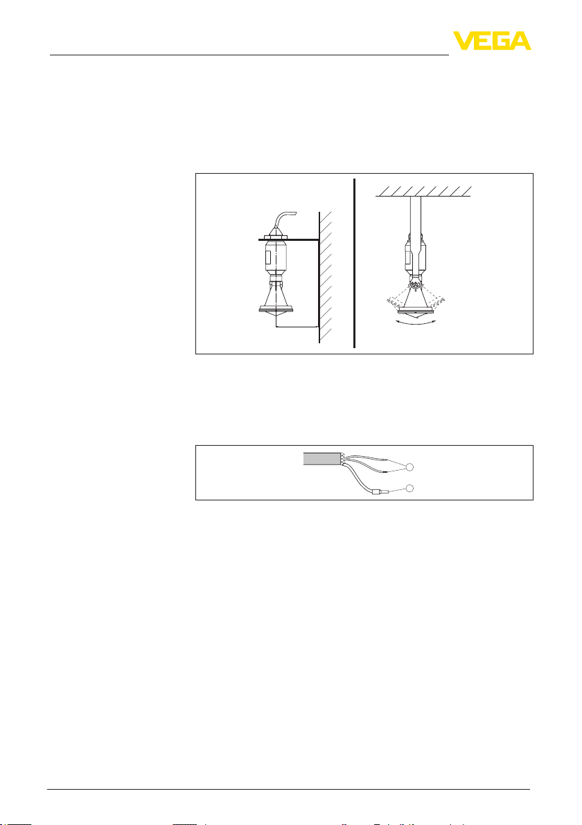
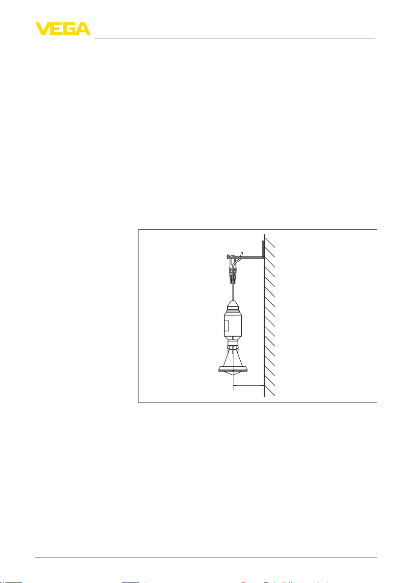
1. Distance antenna to vessel wall > 200 mm
2. Orientation with mounting strap
> 200 mm
(7.87
")
Fig. 1: Distance antenna to vessel wall, orientation with mounting strap
For further information see chapter "Mounting".
1. Make sure that the power supply corresponds to the specications on the type label.
2. Connect the instrument according to the following illustration:
Set parameters
Parameterization example
2
1
2
Fig. 2: Wire assignment x-connected connection cable
1 brown (+) and blue (-) to power supply or to the processing system
2 Shielding
For further information see chapter "Connecting to power supply".
1. Connect interface adapter
2. Start PACTware and then start the "VEGA project assistant".
3. Start the setup assistant in the DTM window and carry out the
predetermined steps.
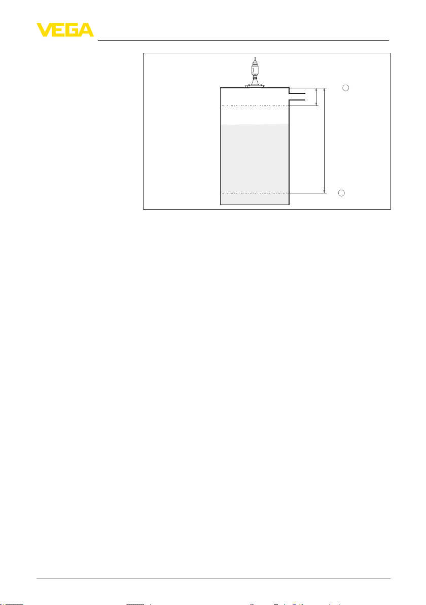
The radar sensor measures the distance from the sensor to the
product surface. For indication of the real level, an allocation of the
measured distance to the percentage height must be carried out.
38061-EN-121011
VEGAPULS WL 61 • 4 … 20 mA/HART - two-wire
Page 3
Further steps
Quick start
100%
2
")
0,5 m
(19.68
")
5 m
(196.85
0%
1
Fig. 3: Parameterization example
1 Min. level = max. meas. distance
2 Max. level = min. meas. distance
For this adjustment, the distance is entered for min. and max. level.
If these values are not known, an adjustment with distances, for
example, of 10 % and 90 % is also possible. Starting point for these
distance specications is always the seal surface of the ange.
1. In the menu "Additional settings", menu item "Damping" you have
to adjust the requested damping of the output signal.
2. Select the output characteristics in the menu item "Current out-
put".
The quick start is then nished. For further information see chapter
"Set up with PACTware".
38061-EN-121011
VEGAPULS WL 61 • 4 … 20 mA/HART - two-wire
3
Page 4

Contents
Contents
1 About this document
1.1 Function ............................................................................. 6
1.2 Target group ....................................................................... 6
1.3 Symbolism used ................................................................. 6
2 For your safety
2.1 Authorised personnel ......................................................... 7
2.2 Appropriate use .................................................................. 7
2.3 Warning about incorrect use ............................................... 7
2.4 General safety instructions ................................................. 7
2.5 CE conformity ..................................................................... 8
2.6 NAMUR recommendations ................................................ 8
2.7 Radio license for Europe .................................................... 8
2.8 Environmental instructions ................................................. 8
3 Product description
3.1 Conguration .................................................................... 10
3.2 Principle of operation ........................................................ 11
3.3 Packaging, transport and storage ..................................... 11
3.4 Accessories and replacement parts ................................. 12
4 Mounting
4.1 General instructions ......................................................... 13
4.2 Mounting versions ............................................................ 13
4.3 Mounting preparations, mounting strap ............................ 16
4.4 Instructions for installation ................................................ 17
5 Connecting to power supply
5.1 Preparing the connection ................................................. 23
5.2 Wiring plan ....................................................................... 23
5.3 Switch-on phase ............................................................... 23
6 Set up with VEGADIS 62
6.1 Connection ....................................................................... 25
6.2 Adjust the sensor .............................................................. 25
6.3 Scale the indication .......................................................... 26
7 Setup with PACTware
7.1 Connect the PC ................................................................ 28
7.2 Parameter adjustment with PACTware .............................. 29
7.3 Saving the parameter adjustment data ............................. 31
8 Set up with other systems
8.1 DD adjustment programs ................................................. 32
8.2 Communicator 375, 475 ................................................... 32
9 Diagnosis, Asset Management and service
9.1 Maintenance .................................................................... 33
9.2 Measured value and event memory ................................. 33
9.3 Asset Management function ............................................. 34
9.4 Rectify faults ..................................................................... 37
9.5 Software update ............................................................... 41
9.6 How to proceed in case of repair ...................................... 41
38061-EN-121011
4
VEGAPULS WL 61 • 4 … 20 mA/HART - two-wire
Page 5

10 Dismounting
10.1 Dismounting steps ............................................................ 43
10.2 Disposal ........................................................................... 43
11 Supplement
11.1 Technical data .................................................................. 44
11.2 Radio astronomy stations ................................................. 49
11.3 Dimensions ...................................................................... 49
Contents
Safety instructions for Ex areas
Please note the Ex-specic safety information for installation and operation in Ex areas. These safety instructions are part of the operating
instructions manual and come with the Ex-approved instruments.
38061-EN-121011
VEGAPULS WL 61 • 4 … 20 mA/HART - two-wire
Editing status: 2012-09-27
5
Page 6
1 About this document
1 About this document
1.1 Function
This operating instructions manual provides all the information you
need for mounting, connection and setup as well as important instructions for maintenance and fault rectication. Please read this information before putting the instrument into operation and keep this manual
accessible in the immediate vicinity of the device.
1.2 Target group
This operating instructions manual is directed to trained qualied
personnel. The contents of this manual should be made available to
these personnel and put into practice by them.
1.3 Symbolism used
Information, tip, note
This symbol indicates helpful additional information.
Caution: If this warning is ignored, faults or malfunctions can result.
Warning: If this warning is ignored, injury to persons and/or serious
damage to the instrument can result.
Danger: If this warning is ignored, serious injury to persons and/or
destruction of the instrument can result.
Ex applications
This symbol indicates special instructions for Ex applications.
List
•
The dot set in front indicates a list with no implied sequence.
Action
→
This arrow indicates a single action.
1 Sequence
Numbers set in front indicate successive steps in a procedure.
Battery disposal
This symbol indicates special information about the disposal of batteries and accumulators.
38061-EN-121011
6
VEGAPULS WL 61 • 4 … 20 mA/HART - two-wire
Page 7

2 For your safety
2 For your safety
2.1 Authorised personnel
All operations described in this operating instructions manual must
be carried out only by trained specialist personnel authorised by the
plant operator.
During work on and with the device the required personal protective
equipment must always be worn.
2.2 Appropriate use
VEGAPULS WL 61 is a sensor for continuous level measurement.
You can nd detailed information on the application range in chapter
"Product description".
Operational reliability is ensured only if the instrument is properly
used according to the specications in the operating instructions
manual as well as possible supplementary instructions.
2.3 Warning about incorrect use
Inappropriate or incorrect use of the instrument can give rise to
application-specic hazards, e.g. vessel overll or damage to system
components through incorrect mounting or adjustment.
2.4 General safety instructions
This is a state-of-the-art instrument complying with all prevailing
regulations and guidelines. The instrument must only be operated in a
technically awless and reliable condition. The operator is responsible
for the trouble-free operation of the instrument.
During the entire duration of use, the user is obliged to determine the
compliance of the necessary occupational safety measures with the
current valid rules and regulations and also take note of new regulations.
The safety instructions in this operating instructions manual, the national installation standards as well as the valid safety regulations and
accident prevention rules must be observed by the user.
For safety and warranty reasons, any invasive work on the device
beyond that described in the operating instructions manual may be
carried out only by personnel authorised by the manufacturer. Arbitrary conversions or modications are explicitly forbidden.
The safety approval markings and safety tips on the device must also
be observed.
Depending on the instrument version, the emitting frequencies are in
the C or K band range. The low emitting frequencies are far below the
internationally approved limit values. When used correctly, there is no
danger to health.
38061-EN-121011
VEGAPULS WL 61 • 4 … 20 mA/HART - two-wire
7
Page 8

2 For your safety
2.5 CE conformity
The device fullls the legal requirements of the applicable EC guidelines. By axing the CE marking, we conrm successful testing of the
product.
You can nd the conformity certicate in the download section of our
homepage.
2.6 NAMUR recommendations
NAMUR is the automation technology user association in the process
industry in Germany. The published NAMUR recommendations are
accepted as the standard in eld instrumentation.
The device fullls the requirements of the following NAMUR recommendations:
NE 43 – Signal level for malfunction information from measuring
•
transducers
NE 53 – Compatibility of eld devices and indicating/adjustment
•
components
NE 107 - Self-monitoring and diagnosis of eld devices
•
For further information see www.namur.de.
2.7 Radio license for Europe
The instrument meets the LPR (Level Probing Radar) radio standard
EN 302729-1/2. It is approved for unrestricted use inside and outside
of closed vessels in countries of the EU and EFTA that have implemented this standard: Austria, Belgium, Bulgaria, Germany, Denmark,
Estonia, France, Greece, Great Britain, Ireland, Island, Italy, Liechtenstein, Lithuania, Latvia, Luxembourg, Malta, Netherlands, Norway,
Poland, Portugal, Romania, Sweden, Switzerland, Slovakia, Slovenia,
Spain, Czech Republik and Cyprus.
Not included in the CE conrmity declaration are the countries implementing this radio standard at a later date: Finland and Hungary.
For operation outside of closed vessels, the following conditions must
be fullled:
The installation must be carried out by trained qualied personnel
•
The instrument must be stationary mounted and the antenna
•
directed vertically downward
The mounting location must be at least 4 km away from the radio
•
astronomy stations listed in the supplement, unless special permission was granted by the responsible national approval authority
When installed within 4 to 40 km of one of the radio astronomy sta-
•
tions listed in the supplyment, the instrument must not be mounted
higher than 15 m above the ground.
2.8 Environmental instructions
Protection of the environment is one of our most important duties.
That is why we have introduced an environment management system
with the goal of continuously improving company environmental pro-
38061-EN-121011
8
VEGAPULS WL 61 • 4 … 20 mA/HART - two-wire
Page 9

2 For your safety
tection. The environment management system is certied according
to DIN EN ISO 14001.
Please help us full this obligation by observing the environmental
instructions in this manual:
Chapter "Packaging, transport and storage"
•
Chapter "Disposal"
•
38061-EN-121011
VEGAPULS WL 61 • 4 … 20 mA/HART - two-wire
9
Page 10
3 Product description
Type label
3 Product description
3.1 Conguration
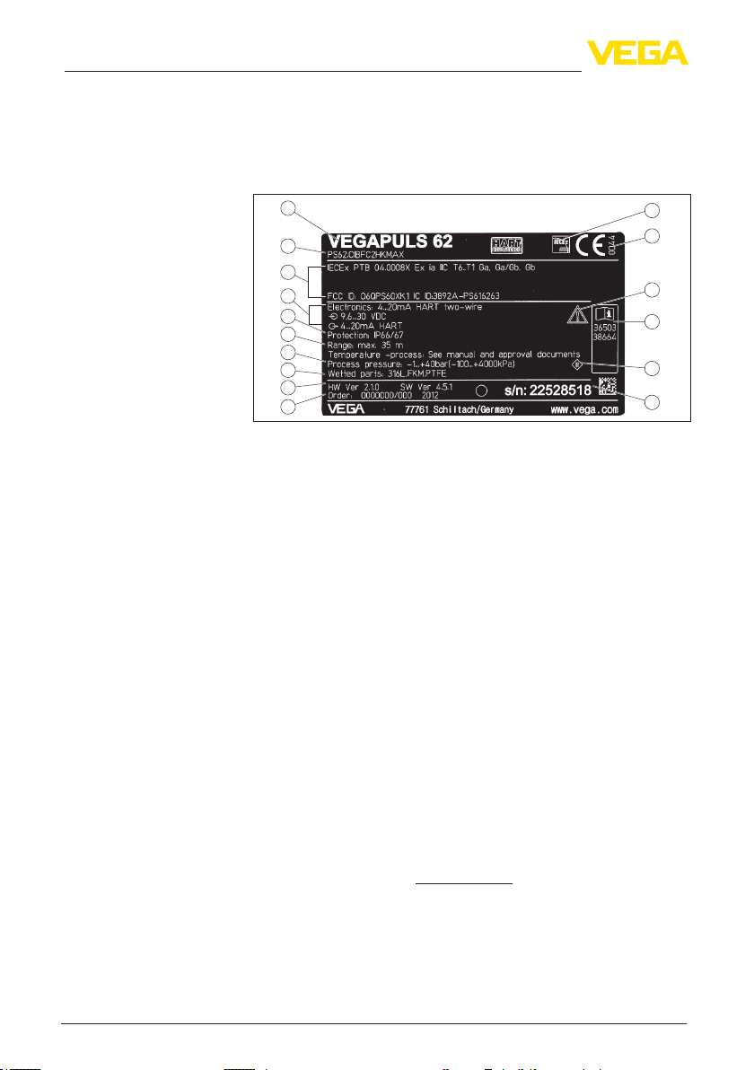
The type label contains the most important data for identication and
use of the instrument:
1
2
3
4
5
6
7
8
9
10
Fig. 4: Layout of the type label (example)
1 Instrument type
2 Product code
3 Approvals
4 Power supply and signal output, electronics
5 Protection rating
6 Measuring range
7 Process and ambient temperature, process pressure
8 Material, wetted parts
9 Hardware and software version
10 Order number
11 Serial number of the instrument
12 Symbol of the device protection class
13 ID numbers, instrument documentation
14 Note to observe the instrument documentation
15 Notied authority for CE marking
16 Approval directive
16
15
14
13
12
11
Serial number
Scope of this operating
instructions manual
10
With the serial number of the instrument on the type label you have
access to the following data on our homepage:
Article number of the instrument (HTML)
•
Delivery date (HTML)
•
Order-specic instrument features (HTML)
•
Operating instructions at the time of shipment (PDF)
•
Order-specic sensor data for an electronics exchange (XML)
•
Test certicate "Measuring Accuracy" (PDF)
•
For this purpose, move to www.vega.com and "VEGA Tools".
This operating instructions manual applies to the following instrument
versions:
Hardware from 1.0.0
•
Software from 4.4.0
•
VEGAPULS WL 61 • 4 … 20 mA/HART - two-wire
38061-EN-121011
Page 11

3 Product description
Scope of delivery
Application area
Functional principle
Packaging
The scope of delivery encompasses:
Radar sensor
•
Compression ange (option)
•
Mounting strap with xing material (optional)
•
Documentation
•
– this operating instructions manual
– Ex-specic "Safety instructions" (with Ex versions)
– if necessary, further certicates
3.2 Principle of operation
The radar sensor VEGAPULS WL 61 is the ideal sensor for all applications in the water and waste water industry. It is particularly suitable
for level measurement in water treatment, in pump stations as well as
storm water overow tanks, for ow measurement in open umes and
for gauge measurement.
The antenna of the radar sensor emits short radar pulses with a
duration of approx. 1 ns. These pulses are reected by the product
and received by the antenna as echoes. The transit time of the radar
pulses from emission to reception is proportional to the distance and
hence to the level. The determined level is converted into an appropriate output signal and outputted as measured value.
3.3 Packaging, transport and storage
Your instrument was protected by packaging during transport. Its
capacity to handle normal loads during transport is assured by a test
according to DIN EN 24180.
The packaging of standard instruments consists of environmentfriendly, recyclable cardboard. For special versions, PE foam or PE
foil is also used. Dispose of the packaging material via specialised
recycling companies.
Transport
Transport inspection
Storage
38061-EN-121011
VEGAPULS WL 61 • 4 … 20 mA/HART - two-wire
Transport must be carried out under consideration of the notes on the
transport packaging. Nonobservance of these instructions can cause
damage to the device.
The delivery must be checked for completeness and possible transit
damage immediately at receipt. Ascertained transit damage or concealed defects must be appropriately dealt with.
Up to the time of installation, the packages must be left closed and
stored according to the orientation and storage markings on the
outside.
Unless otherwise indicated, the packages must be stored only under
the following conditions:
Not in the open
•
Dry and dust free
•
Not exposed to corrosive media
•
Protected against solar radiation
•
Avoiding mechanical shock and vibration
•
11
Page 12

3 Product description
Storage and transport
temperature
Interface adapter
External indicating and
adjustment unit with
HART protocol
Storage and transport temperature see chapter "Supplement -
•
Technical data - Ambient conditions"
Relative humidity 20 … 85 %
•
3.4 Accessories and replacement parts
The interface adapter VEGACONNECT enables the connection of
communication-capable instruments to the USB interface of a PC. For
parameter adjustment of these instruments, an adjustment software
such as PACTware with VEGA-DTM is required.
You can nd further information in the operating instructions "Interface
adapter VEGACONNECT" (Document-ID 32628).
VEGADIS 62 is suitable for measured value indication and adjustment
of sensors with HART protocol. It is looped into the 4 … 20 mA/HART
signal cable.
You can nd further information in the operating instructions "VE-
GADIS 62" (Document-ID 36469).
12
38061-EN-121011
VEGAPULS WL 61 • 4 … 20 mA/HART - two-wire
Page 13
Suitability for the process
conditions
Straining clamp
4 Mounting
4 Mounting
4.1 General instructions
Make sure that all parts of the instrument exposed to the process, in
particular the active measuring component, process seal and process
tting, are suitable for the existing process conditions. These include
above all the process pressure, process temperature as well as the
chemical properties of the medium.
You can nd the specications in chapter "Technical data" and on the
type label.
4.2 Mounting versions
Most simply mount the instrument via the straining clamp. For this
purpose, the connection cable is provided with a strain relief wire of
Kevlar.
In order to avoid faulty measured values, make sure that the sensor
does not oscillate.
Fig. 5: Mounting via a straining clamp
Mounting bracket
38061-EN-121011
VEGAPULS WL 61 • 4 … 20 mA/HART - two-wire
For a rigid mounting, a mounting bracket with opening for thread
G1½, e.g. from the VEGA product range, is recommended. The
mounting of the sensor in the bracket is carried out via a G1½ counter
nut of plastic. Take note of chapter "Mounting instructions" for the
distance to the wall.
> 200 mm
(7.87")
13
Page 14
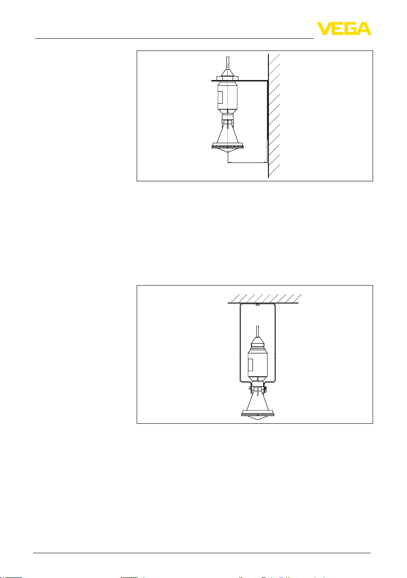
4 Mounting
> 200 mm
(7.87
Fig. 6: Mounting via a mounting bracket
")
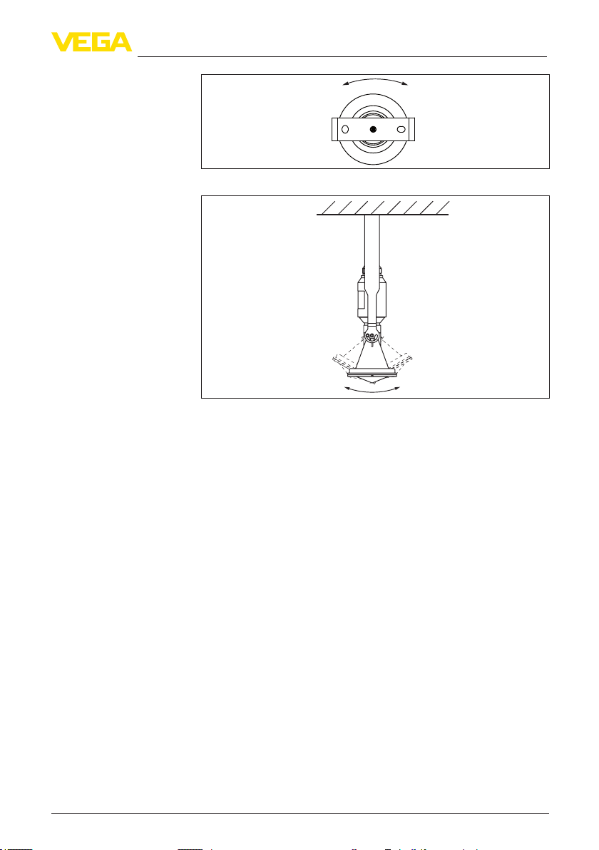
Mounting strap
The optional mounting strap enables sensor mounting on e.g. a ceiling, wall or bracket. It is available in the following versions:
Length 300 mm for ceiling mounting
•
Length 170 mm for wall mounting
•
The instrument is normally mounted vertically on the ceiling.
This ensures swivelling of the sensor up to 180° for optimum orienta-
tion.
Fig. 7: Vertical mounting on the ceiling via the mounting strap with length
300 mm
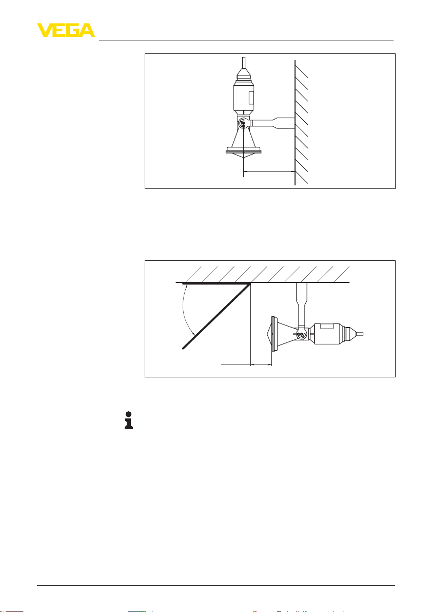
As an alternative, mounting can be carried out vertically on the wall.
38061-EN-121011
14
VEGAPULS WL 61 • 4 … 20 mA/HART - two-wire
Page 15
4 Mounting
> 200 mm
(7.87")
Fig. 8: Vertical mounting on the wall via the mounting strap with length 170 mm
Some measuring points have only very little space between ceiling and water surface. In such cases, for example in closed storm
overow basins, horizontal mounting of the sensor is recommended.
The radar impulses must be directed via a 45° reector - for example
a stainless steel sheet - to the water surface.
45°
Fig. 9: Horizontal mounting with a mounting strap of length 170 mm with reector provided by the customer
Information:
With this mounting arrangement, the reference plane mentioned in
chapter "Technical data" no longer applies. There is an oset that
must be taken into account for the adjustment. Note the distance
measured at min. level with the reector, for example 2.5 m. Enter
this value as min. adjustment/measuring range begin. Determine the
dierence between the min. and max. level, for example 1 m. The distance for the max. adjustment results from 2.5 m - 1 m = 1.5 m. Enter
this value as max. adjustment/measuring range end.
38061-EN-121011
VEGAPULS WL 61 • 4 … 20 mA/HART - two-wire
> 50 mm
(1.97")
15
Page 16
4 Mounting
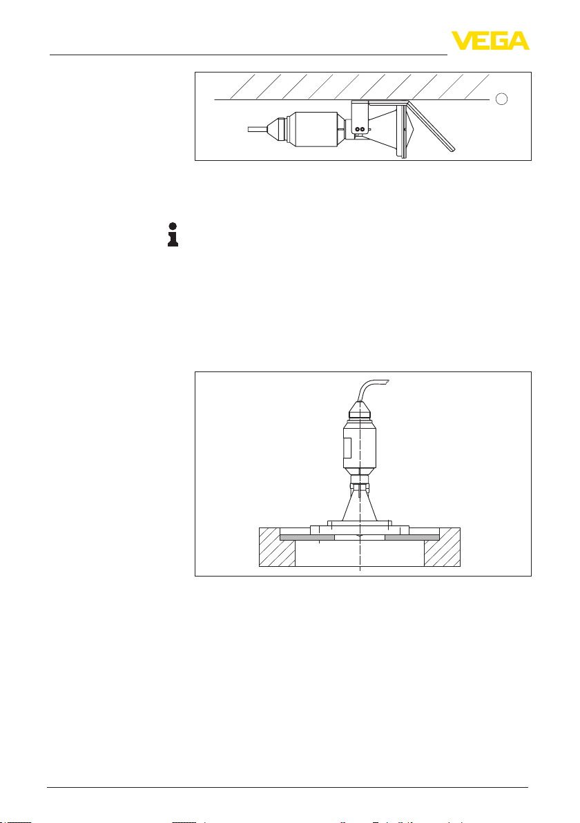
1
Fig. 10: Horizontal mounting with the optional mounting strap with integrated
reector
1 Reference plane
Information:
With this combination (by default), the oset is already taken into account. The lower side of the mountng seal is the reference plane.
Flange
For mounting the instrument on a socket or a manhole cover, an unassembled combination compression ange is optionally available for
DN 80 (ASME 3" or JIS 80), also as a retrotting part. As an alternative, the instrument can be already supplied with a tight, x-mounted
adapter ange from DN 100 (ASME 4" or JIS 100).
You can nd drawings of these mounting options in chapter "Dimen-
sions".
Fig. 11: Mounting by means of an adapter ange, for example, on a manhole lid.
4.3 Mounting preparations, mounting strap
The optional mounting strap is supplied unassembled. It must be
screwed to the sensor before setup with the attached screws. Max.
torque, see chapter "Technical data". Required tools: Allen wrench
size 4.
There are two dierent ways of screwing the strap to the sensor.
Depending on the selected method, the sensor can be rotated in
the strap innitely variable through 180° or in three steps 0°, 90° and
180°.
38061-EN-121011
16
VEGAPULS WL 61 • 4 … 20 mA/HART - two-wire
Page 17
Tight installation of the
plastic horn antenna
4 Mounting
Fig. 12: Rotation in the centre with ceiling mounting
Fig. 13: Adjustment of the angle of inclination in case of wall mounting
4.4 Instructions for installation
For tight installation of the version with plastic horn antenna with compression or adapter ange, the following conditions must be fullled:
1. Use suitable at seal, e.g. of EPDM with Shore hardness 25 or 50
2. Make sure the number of ange screws corresponds to the number of ange holes
3. Tighten all screws with the torque stated in the technical data
Polarisation plane
38061-EN-121011
VEGAPULS WL 61 • 4 … 20 mA/HART - two-wire
The emitted radar impulses of the radar sensor are electromagnetic
waves. The polarisation plane is the direction of the electrical wave
component. By turning the instrument in the connection ange or
mounting strap, the polarisation can be used to reduce the eects of
false echoes.
The position of the polarisation level is marked by marking bars on the
instrument.
17
Page 18
4 Mounting
1
Fig. 14: Position of the polarisation level
1 Marking bar
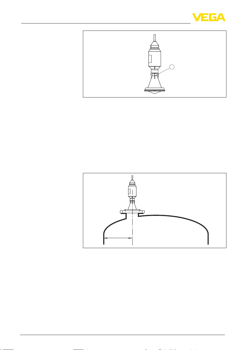
Installation position
When mounting the sensor, keep a distance of at least 200 mm
(7.874 in) to the vessel wall. If the sensor is installed in the center of
dished or round vessel tops, multiple echoes can arise. These can,
however, be suppressed by an appropriate adjustment (see chapter
"Setup").
If you cannot keep this distance you should carry out a false echo
storage before setup. This applies mainly if buildup on the vessel wall
is expected. In this case, we recommend repeating a false echo storage later with existing buildup.
> 200 mm
(7.87
")
Fig. 15: Mounting of the radar sensor on round vessel tops
In vessels with conical bottom it can be advantageous to mount the
sensor in the center of the vessel, as measurement is then possible
down to the lowest point of the vessel bottom.
18
38061-EN-121011
VEGAPULS WL 61 • 4 … 20 mA/HART - two-wire
Page 19

Fig. 16: Mounting of the radar sensor on vessels with conical bottom
4 Mounting
Inowingmedium
Socket
Do not mount the instrument in or above the lling stream. Make sure
that you detect the product surface, not the inowing product.
Fig. 17: Mounting of the radar sensor with inowing medium
Approximate values of the socket heights are shown in the following
illustration. The socket end should be smooth and burr-free, if possible also rounded. After mounting, you have to carry out a false signal
memory during the parameter adjustment.
38061-EN-121011
VEGAPULS WL 61 • 4 … 20 mA/HART - two-wire
19
Page 20

4 Mounting
Sensor orientation
Vessel installations
300 mm / 11.8
"
"
500 mm / 19.69
600 mm / 23.6
"
800 mm / 31.5
h
"
"
"
"
d
h
d
80 mm / 3.15
100 mm / 4
125 mm / 5"
150 mm / 6
Fig. 18: Deviating socket dimensions
Direct the sensor as perpendicular as possible to the product surface
to achieve optimum measurement results.
Fig. 19: Orientation of the sensor
The mounting location of the radar sensor should be a place where no
other equipment or xtures cross the path of the microwave signals.
Vessel installations, such as e.g. ladders, limit switches, heating spirals, struts, etc., can cause false echoes and impair the useful echo.
Make sure when planning your measuring site that the radar sensor
has a "clear view" to the measured product.
In case of existing vessel installations, a false echo storage should be
carried out during setup.
If large vessel installations such as struts or supports cause false
echoes, these can be attenuated through supplementary measures.
Small, inclined sheet metal baes above the installations scatter the
radar signals and prevent direct interfering reections.
20
38061-EN-121011
Fig. 20: Cover smooth proles with deectors
VEGAPULS WL 61 • 4 … 20 mA/HART - two-wire
Page 21

4 Mounting
Foam generation
Flow measurement with
rectangularume
Through the action of lling, stirring and other processes in the vessel,
compact foams that considerably damp the emitted signals may form
on the product surface.
If foams are causing measurement errors, the biggest possible radar
antennas, the electronics with increased sensitivity or low frequency
radar sensors (C band) should be used.
As an alternative, sensors with guided microwave can be used. These
are unaected by foam generation and are best suited for such applications.
The short examples give you introductory information on the ow
measurement. Detailed planning information is available from ume
manufacturers and in special literature.
3 ... 4 h
90°
2 3
Fig. 21: Flow measurement with rectangular ume: d
sensor (see chapter "Technical data"); h
ume
1 Overow orice (side view)
2 Headwater
3 Tail water
4 Overfall orice (view from bottom water)
1
max
≥ 50 mm
min
d
h
≥ 2 mm x h
90°
max
max
4
= min. distance of the
min.
= max. lling of the rectangular
max.
In general, the following points must be observed:
Install the sensor on the headwater side
•
Installation in the centre of the ume and vertical to the liquid
•
surface
Distance to the overfall orice
•
Distance of orice opening above ground
•
Min. distance of the orice opening to bottom water
•
Min. distance of the sensor to max. storage level
•
38061-EN-121011
VEGAPULS WL 61 • 4 … 20 mA/HART - two-wire
21
Page 22

4 Mounting
Flow measurement with
KhafagiVenturiume
3 ... 4 x h
d
max
90°
h
max
2
1
Fig. 22: Flow measurement with Khafagi-Venturi ume: d = Min. distance to sensor; h
= max. lling of the ume; B = tightest constriction in the ume
max.
1 Position sensor
2 Venturi ume
B
In general, the following points must be observed:
Installation of the sensor at the inlet side
•
Installation in the centre of the ume and vertical to the liquid
•
surface
Distance to the Venturi ume
•
Min. distance of the sensor to max. storage level
•
22
38061-EN-121011
VEGAPULS WL 61 • 4 … 20 mA/HART - two-wire
Page 23

Safety instructions
5 Connecting to power supply
5 Connecting to power supply
5.1 Preparing the connection
Always keep in mind the following safety instructions:
Connect only in the complete absence of line voltage
•
If overvoltage surges are expected, overvoltage arresters should
•
be installed
Voltage supply
Connection cable
Wire assignment, connection cable
Power supply and current signal are carried on the same two-wire
cable. The voltage supply range can dier depending on the instrument version.
The data for power supply are specied in chapter "Technical data".
Provide a reliable separation between the supply circuit and the
mains circuits according to DIN VDE 0106 part 101.
Keep in mind the following additional factors that inuence the operat-
ing voltage:
Output voltage of the power supply unit can be lower under nomi-
•
nal load (with a sensor current of 20.5 mA or 22 mA in case of fault
message)
Inuence of additional instruments in the circuit (see load values in
•
chapter "Technical data")
The instrument is connected with standard two-wire cable without
screen. If electromagnetic interference is expected which is above the
test values of EN 61326-1 for industrial areas, screened cable should
be used.
For instruments with housing and cable gland, use cable with round
cross-section. A cable outer diameter of 5 … 9 mm (0.2 … 0.35 in)
ensures the seal eect of the cable gland. If you are using cable with
a dierent diameter, exchange the seal or use a suitable cable gland.
We generally recommend the use of screened cable for HART multidrop mode.
5.2 Wiring plan
1
Fig. 23: Wire assignment x-connected connection cable
1 brown (+) and blue (-) to power supply or to the processing system
2 Shielding
5.3 Switch-on phase
After connecting the instrument to power supply or after a voltage
recurrence, the instrument carries out a self-check for approx. 30 s:
38061-EN-121011
VEGAPULS WL 61 • 4 … 20 mA/HART - two-wire
2
23
Page 24

5 Connecting to power supply
Internal check of the electronics
•
Indication of the instrument type, hardware and software version,
•
measurement loop name on the display or PC
Indication of the status message "F 105 Determine measured
•
value" on the display or PC
The output signal jumps to the set error current
•
As soon as a plausible measured value is found, the corresponding
current is outputted to the signal cable. The value corresponds to the
actual level as well as the settings already carried out, e.g. factory
setting.
24
38061-EN-121011
VEGAPULS WL 61 • 4 … 20 mA/HART - two-wire
Page 25

6 Set up with VEGADIS 62
6 Set up with VEGADIS 62
6.1 Connection
The VEGADIS 62 is an indicating and adjustment unit without external
energy for looping into 4 … 20 mA/HART circuits.
The parameter adjustment of the sensor is carried out via HART communication. During the parameter adjustment, the VEGADIS 62 acts
as a Secondary Master with respect to the sensor.
=
~
2
1
Fig. 24: Connection of VEGADIS 62 to the sensor
1 Sensor
2 VEGADIS 62
3 HART resistance > 150 Ω (necessary with low impedance power supply)
4 Voltage supply/Processing
The following adjustment volume of the connected HART sensor is
available:
Min./Max. adjustment
•
zero/span adjustment (live adjustment)
•
Damping
•
43
6.2 Adjust the sensor
Proceed as follows for the min./max. adjustment of the sensor:
1. Press "OK" to reach the adjustment menu.
2. Select the submenu "Measurement" and conrm with "OK".
3. Move to the menu item "Unit". There the instrument unit of the
sensor is displayed, for example "m".
4. Move to the menu item "MB begin", there the max. measuring
distance is displayed, for example the default setting 15 m.
38061-EN-121011
VEGAPULS WL 61 • 4 … 20 mA/HART - two-wire
25
Page 26

6 Set up with VEGADIS 62
5. Edit value via "OK" and adjust the requested value, for example,
5 m.
6. Save value with "OK", VEGAPULS WL 61 displays briey "Wait",
then the value is taken over into the sensor.
7. Move to the menu item "MB end", there the min. measuring distance is displayed, for example the default setting 0 m.
8. Proceed accordingly for "MB end", enter for example the value
1 m and store.
The min./max. adjustment is nished.
After "[ESC]", the display shows the actually measured distance as
digital value in m and the level on the bargraph.
Keep in mind that the displayed values are anticyclical. With increas-
ing distance, the 4 … 20 mA value gets smaller and vice versa.
26
6.3 Scale the indication
Proceed as follows for indication of the level as digital value in %:
1. Press "OK" to reach the adjustment menu.
2. Select the submenu "Measurement" and conrm with "OK".
3. Select the menu item "Unit"
38061-EN-121011
4. Select the unit "USER" and conrm with "OK".
VEGAPULS WL 61 • 4 … 20 mA/HART - two-wire
Page 27

6 Set up with VEGADIS 62
Information:
The symbol for HART extinguishes, the HART communication is
switched o.
5. Select the submenu "Indication" and conrm with "OK".
6. Select the menu item "Unit" and conrm with "OK".
7. Select the unit "%" and conrm with "OK".
The conversion to level indication in % is nished. The unit in the
menu "Measurement" must remain at "USER".
After "[ESC]", the display shows the level as digital value in % and on
the bargraph. The indication values are now synchronous.
38061-EN-121011
VEGAPULS WL 61 • 4 … 20 mA/HART - two-wire
27
Page 28

7 Setup with PACTware
7 Setup with PACTware
7.1 Connect the PC
Via interface adapter to
the signal cable
2 4
LOCK
USB
TWIST
3
OPEN
1
5
Fig. 25: Connecting the PC to the signal cable
1 Sensor
2 HART resistance 250 Ω (optional depending on processing)
3 Connection cable with 2 mm pins and terminals
4 Processing system/PLC/Voltage supply
5 Interface adapter, for example VEGACONNECT 4
Note:
With power supply units with integrated HART resistance (internal
resistance approx. 250 Ω), an additional external resistance is not
necessary. This applies, e.g. to the VEGA instruments VEGATRENN
149A, VEGAMET 381, VEGAMET 391. Common Ex separators are
also usually equipped with a sucient current limitation resistance. In
such cases, the interface converter can be connected parallel to the
4 … 20 mA cable (dashed line in the previous illustration).
28
38061-EN-121011
VEGAPULS WL 61 • 4 … 20 mA/HART - two-wire
Page 29

Via interface adapter to
the VEGAMET signal conditioning instrument
Prerequisites
7 Setup with PACTware
3
1
2
1
2
2
TWIST
LOCK
1
OPEN
4
USB
%
on
VEGAMET 381
Fig. 26: Connection of the PC to the VEGAMET signal conditioning instrument
1 Sensor
2 Connection cable with 2 mm pins
3 Signal conditioning instrument, e.g. VEGAMET 381
4 Interface adapter, for example VEGACONNECT 4
7.2 Parameter adjustment with PACTware
For parameter adjustment of the sensor via a Windows PC, the conguration software PACTware and a suitable instrument driver (DTM)
according to FDT standard are required. The up-to-date PACTware
version as well as all available DTMs are compiled in a DTM Collection. The DTMs can also be integrated into other frame applications
according to FDT standard.
Note:
To ensure that all instrument functions are supported, you should
always use the latest DTM Collection. Furthermore, not all described
functions are included in older rmware versions. You can download
the latest instrument software from our homepage. A description of
the update procedure is also available in the Internet.
Further setup steps are described in the operating instructions manual "DTM Collection/PACTware" attached to each DTM Collection and
which can also be downloaded from the Internet. Detailed descriptions are available in the online help of PACTware and the DTMs.
38061-EN-121011
VEGAPULS WL 61 • 4 … 20 mA/HART - two-wire
29
Page 30

7 Setup with PACTware
Fig. 27: Example of a DTM view
Adjustment
Since a radar sensor is a distance measuring instrument, the distance
from the sensor to the product surface is measured. For indication of
the real level, an allocation of the measured distance to the percentage height must be carried out. To perform the adjustment, enter the
distance with full and empty vessel, see the following example:
100%
5 m
")
(196.85
0%
2
1
Fig. 28: Parameterization example
1 Min. level = max. meas. distance
2 Max. level = min. meas. distance
0,5 m
")
(19.68
38061-EN-121011
30
VEGAPULS WL 61 • 4 … 20 mA/HART - two-wire
Page 31

7 Setup with PACTware
If these values are not known, an adjustment with the distances of for
example 10 % and 90 % is possible. Starting point for these distance
specications is always the seal surface of the thread or ange. By
means of these settings, the real level will be calculated.
The real product level during this adjustment is not important, because the min./max. adjustment is always carried out without changing the product level. These settings can be made ahead of time
without the instrument having to be installed.
Standard/Full version
All device DTMs are available as a free-of-charge standard version
and as a full version that must be purchased. In the standard version,
all functions for complete setup are already included. An assistant for
simple project conguration simplies the adjustment considerably.
Saving/printing the project as well as import/export functions are also
part of the standard version.
In the full version there is also an extended print function for complete
project documentation as well as a save function for measured value
and echo curves. In addition, there is a tank calculation program as
well as a multiviewer for display and analysis of the saved measured
value and echo curves.
The standard version is available as a download under www.vega.
com/downloads and "Software". The full version is available on CD
from the agency serving you.
7.3 Saving the parameter adjustment data
We recommend documenting or saving the parameter adjustment
data via PACTware. That way the data are available for multiple use or
service purposes.
38061-EN-121011
VEGAPULS WL 61 • 4 … 20 mA/HART - two-wire
31
Page 32

8 Set up with other systems
8 Set up with other systems
8.1 DD adjustment programs
Device descriptions as Enhanced Device Description (EDD) are
available for DD adjustment programs such as, for example, AMS™
and PDM.
The les can be downloaded at www.vega.com/downloads under
"Software".
8.2 Communicator 375, 475
Device descriptions for the instrument are available as DD or EDD for
parameter adjustment with the Field Communicator 375 or 475.
The les can be downloaded unter www.vega.com/downloads and
"Software".
32
38061-EN-121011
VEGAPULS WL 61 • 4 … 20 mA/HART - two-wire
Page 33

9 Diagnosis, Asset Management and service
9 Diagnosis, Asset Management and service
9.1 Maintenance
If the device is used correctly, no maintenance is required in normal
operation.
9.2 Measured value and event memory
The instrument has several memories which are available for diagnosis purposes. The data remain even with voltage interruption.
Measured value memory
Event memory
Echo curve memory
Up to 60,000 measured values can be stored in the sensor in a ring
memory. Each entry contains date/time as well as the respective
measured value. Storable values are for example:
Distance
•
Filling height
•
Percentage value
•
Lin. percent
•
Scaled
•
Current value
•
Meas. reliability
•
Electronics temperature
•
When the instrument is shipped, the measured value memory is
active and stores distance, measurement certainty and electronics
temperature every 3 minutes.
The requested values and recording conditions are set via a PC with
PACTware/DTM or the control system with EDD. Data are thus read
out and also reset.
Up to 500 events are automatically stored with a time stamp in the
sensor (non-deletable). Each entry contains date/time, event type,
event description and value. Event types are for example:
Modication of a parameter
•
Switching on and o times
•
Status messages (according to NE 107)
•
Error messages (according to NE 107)
•
The data are read out via a PC with PACTware/DTM or the control
system with EDD.
The echo curves are stored with date and time and the corresponding
echo data. The memory is divided into two sections:
Echo curve of the setup: This is used as reference echo curve for
the measurement conditions during setup. Changes in the measurement conditions during operation or buildup on the sensor can thus
be recognized. The echo curve of the setup is stored via:
PC with PACTware/DTM
•
Control system with EDD
•
Indicating and adjustment module
•
38061-EN-121011
VEGAPULS WL 61 • 4 … 20 mA/HART - two-wire
33
Page 34

9 Diagnosis, Asset Management and service
Further echo curves: Up to 10 echo curves can be stored in a ring
buer in this memory section. Further echo curves are stored via:
PC with PACTware/DTM
•
Control system with EDD
•
9.3 Asset Management function
The instrument features self-monitoring and diagnostics according
to NE 107 and VDI/VDE 2650. In addition to the status messages in
the following tables there are more detailed error messages available
under the menu item "Diagnostics" via the indicating and adjustment
module, PACTware/DTM and EDD.
Status messages
The status messages are classied in the following categories:
Failure
•
Function check
•
Out of specication
•
Maintenance requirement
•
and explained by pictographs:
41 2 3
Fig. 29: Pictograms of the status messages
1 Failure - red
2 Function check - orange
3 Out of specication - yellow
4 Maintenance - blue
Failure: Due to a malfunction in the instrument, a failure message is
outputted.
This status message is always active. It cannot be deactivated by the
user.
Function check: The instrument is in operation, the measured value
is temporarily invalid (for example during simulation).
This status message is inactive by default. It can be activated by the
user via PACTware/DTM or EDD.
Outofspecication: The measured value is unstable because the
instrument specication is exceeded (e.g. electronics temperature).
This status message is inactive by default. It can be activated by the
user via PACTware/DTM or EDD.
Maintenance: Due to external inuences, the instrument function
is limited. The measurement is aected, but the measured value is
still valid. Plan in maintenance for the instrument because a failure is
expected in the near future (e.g. due to buildup).
This status message is inactive by default. It can be activated by the
user via PACTware/DTM or EDD.
38061-EN-121011
34
VEGAPULS WL 61 • 4 … 20 mA/HART - two-wire
Page 35

9 Diagnosis, Asset Management and service
Failure
The following table shows the error codes and text messages in the
status message "Failure" and gives information on the cause and how
to eliminate it. Keep in mind that some specications are only valid for
four-wire instruments and the electronics of VEGAPULS WL 61 cannot be exchanged by the user.
Code
Text message
F013
no measured
value available
F017
Adjustment
span too small
F025
Error in the
linearization
table
F036
No operable
software
F040
Error in the
electronics
F080 – General software error – Separate operating voltage
F105
Determine
measured
value
F113
Communica-
tion error
F125
Unpermissi-
ble electronics
temperature
F260
Error in the
calibration
Cause Rectication
– Sensor does not detect an
echo during operation
– Antenna system contami-
nated or defective
– Adjustment not within
specication
– Index markers are not con-
tinuously rising, for examle
unlogical value pairs
– Failed or interrupted soft-
ware update
– Hardware defect – Exchanging the electronics
– The instrument is still in the
start phase, the measured
value could not yet be
determined
– EMC interferences
– Transmission error with the
external communication
with 4-wire power supply
unit
– Temperature of the elec-
tronics in the non-specied
section
– Error in the calibration car-
ried out in the factory
– Error in the EEPROM
– Check or correct installation
and/or parameter adjust-
ment
– Clean or exchange process
component or antenna
– Change adjustment accord-
ing to the limit values (difference between min. and
max. ≥ 10 mm)
– Check linearization table
– Delete table/Create new
– Repeat software update
– Check electronics version
– Exchanging the electronics
– Send instrument for repair
– Send instrument for repair
briey
– Wait for the warm-up phase
– Duration depending on
the version and parameter
adjustment up to approximately 3 min.
– Remove EMC inuences
– Exchange 4-wire power
supply unit or electronics
– Check ambient temperature
– Isolate electronics
– Use instrument with higher
temperature range
– Exchanging the electronics
– Send instrument for repair
38061-EN-121011
VEGAPULS WL 61 • 4 … 20 mA/HART - two-wire
35
Page 36

9 Diagnosis, Asset Management and service
Function check
Outofspecication
Code
Text message
F261
Error in the
conguration
F264
Installation/
Setup error
F265
Measurement
function disturbed
Cause Rectication
– Error during setup
– False signal suppression
faulty
– Error when carrying out a
reset
– Adjustment not within the
vessel height/measuring
range
– Max. measuring range of
the instrument not sucient
– Sensor no longer carries
out a measurement
– Operating voltage too low
– Repeat setup
– Repeat reset
– Check or correct installation
and/or parameter adjust-
ment
– Use an instrument with big-
ger measuring range
– Check operating voltage
– Carry out a reset
– Separate operating voltage
briey
The following table shows the error codes and text messages in the
status message "Function check" and provides information on causes
as well as corrective measures.
Code
Text message
C700
Simulation ac-
tive
Cause Rectication
– A simulation is active – Finish simulation
– Wait for the automatic end
after 60 mins.
The following table shows the error codes and text messages in the
status message "Out of specication" and provides information on
causes as well as corrective measures.
Code
Text message
S600
Unpermissible electronics
temperature
S601
Overlling
Cause Rectication
– Temperature of the elec-
tronics in the non-specied
section
– Danger of vessel overlling – Make sure that there is no
– Check ambient temperature
– Isolate electronics
– Use instrument with higher
temperature range
further lling
– Check level in the vessel
Maintenance
36
The following table shows the error codes and text messages in the
status message "Maintenance" and provides information on causes
as well as corrective measures.
VEGAPULS WL 61 • 4 … 20 mA/HART - two-wire
38061-EN-121011
Page 37

9 Diagnosis, Asset Management and service
Code
Text message
M500
Error with the
reset delivery
status
M501
Error in the
non-active
linearization
table
M502
Error in the
diagnosis
memory
M503
Reliability too
low
M504
Error on an
device interface
M505
No echo avail-
able
Cause Rectication
– With the reset to delivery
status, the data could not
be restored
– Hardware error EEPROM – Exchanging the electronics
– Hardware error EEPROM – Exchanging the electronics
– The echot/noise ratio is the
small for a reliable meas-
urement
– Hardware defect – Check connections
– Level echo can no longer
be detected
– Repeat reset
– Load XML le with sensor
data into the sensor
– Send instrument for repair
– Send instrument for repair
– Check installation and
process conditions
– Clean the antenna
– Change polarisation direc-
tion
– Use instrument with higher
sensitivity
– Exchanging the electronics
– Send instrument for repair
– Clean the antenna
– Use a more suitable
antenna/sensor
– Remove possible false
echoes
– Optimize sensor position
and orientation
9.4 Rectify faults
Reaction when malfunctions occur
Procedure for fault recti-
cation
Check the 4 … 20 mA
signal
38061-EN-121011
VEGAPULS WL 61 • 4 … 20 mA/HART - two-wire
The operator of the system is responsible for taking suitable measures to rectify faults.
The rst measures are:
Evaluation of fault messages, for example via the indicating and
•
adjustment module
Checking the output signal with 4 … 20 mA instruments
•
Treatment of measurement errors
•
Further comprehensive diagnostics options oer a PC with the software PACTware and the suitable DTM. In many cases, the reasons
can be determined in this way and faults can be rectied.
Connect a handmultimeter in the suitable measuring range according
to the wiring plan. The following table describes possible errors in the
current signal and helps to remove them:
37
Page 38

9 Diagnosis, Asset Management and service
Error Cause Rectication
4 … 20 mA signal
not stable
4 … 20 mA signal
missing
Current signal greater than
22 mA or less
than 3.6 mA
– Level uctua-
tions
– Electrical con-
nection faulty
– Voltage supply
missing
– Operating volt-
age too low or
load resistance
too high
– Electronics
module in the
sensor defective
– Set damping according to the
instrument via the indicating and
adjustment module or PACTware/
DTM
– Check connection according to
chapter "Connection steps" and
if necessary, correct according to
chapter "Wiring plan".
– Check cables for breaks; repair if
necessary
– Check, adapt if necessary
– Exchange the instrument or send it
in for repair
Treatment of measurement errors with liquids
The below tables show typical examples of application-related measurement errors with liquids. The measurement errors are dierentiated
according to the following:
Constant level
•
Filling
•
Emptying
•
The images in column "Error pattern" show the real level with a broken line and the level displayed by the sensor as a continuous line.
Level
1
2
0
1 Real level
2 Level displayed by the sensor
time
Instructions:
Wherever the sensor displays a constant value, the reason could
•
also be the fault setting of the current output to "Hold value"
In case of a too low level indication, the reason could be a line
•
resistance that is too high
38061-EN-121011
38
VEGAPULS WL 61 • 4 … 20 mA/HART - two-wire
Page 39

9 Diagnosis, Asset Management and service
9.4 Measurement error with constant level
Fault description Error pattern Cause Rectication
1. Measured value
shows a too low or too
high level
Level
0
– Min./max. adjustment not
correct
– Wrong linearization curve – Adapt linearization curve
time
– Installation in a bypass tube or
standpipe, hence running time
error (small measurement error
close to 100 %/large error close
– Adapt min./max. adjustment
– Check parameter "Application"
with respect to vessel form,
adapt if necessary (bypass,
standpipe, diameter)
to 0 %)
2. Measured value
jumps towards 0 %
3. Measured value
jumps towards 100 %
Level
– Multiple echo (vessel top,
product surface) with amplitude
higher than the level echo
0
Level
time
– Due to the process, the ampli-
tude of the product echo sinks
– Check parameter "Application",
especially vessel top, product
type, dished end, high dielectric
gure, adapt if necessary
– Carry out false signal suppres-
sion
– A false signal suppression was
0
not carried out
time
– Amplitude or position of a
false echo has changed (e.g.
condensation, buildup); false
signal suppression no longer
– Determine the reason for the
changed false echo, carry out
false signal suppression, e.g.
with condensation
matches
9.4 Measurementerrorduringlling
Fault description Error pattern Cause Rectication
4. Measured value remains unchanged
during lling
5. Measured value remains in the bottom
section during lling
6. Measured value remains momentarily
unchanged during lling and then jumps to
the correct level
Level
– False echoes in the close range
too big or product echo too
small
0
– Strong foam or spout genera-
time
tion
– Max. adjustment not correct
Level
– Echo from the tank bottom
larger than the product echo,
for example, with products with
0
Level
0
εr < 2.5 oil-based, solvents
time
– Turbulence on the product
surface, quick lling
time
– Eliminate false echoes in the
close range
– Check measurement situation:
Antenna must protrude out of
the socket, installations
– Remove contamination on the
antenna
– Minimize interfering instal-
lations in the close range by
changing the polarization
direction
– Create a new false signal sup-
pression
– Adapt max. adjustment
– Check application parameters
Medium, Vessel height and
Floor form, adapt if necessary
– Check application parameters,
change if necessary, e.g. in
dosing vessel, reactor
38061-EN-121011
VEGAPULS WL 61 • 4 … 20 mA/HART - two-wire
39
Page 40

9 Diagnosis, Asset Management and service
Fault description Error pattern Cause Rectication
7. Measured value
jumps towards 0 %
during lling
8. Measured value
jumps towards 100 %
during lling
9. Measured value
jumps sporadically to
100 % during lling
10. Measured value
jumps to ≥ 100 % or
0 m distance
Level
– Amplitude of a multiple echo
(vessel top - product surface) is
larger than the level echo
0
time
– The level echo cannot be distin-
guished from the false echo at
a false echo position (jumps to
multiple echo)
Level
– Due to strong turbulence and
foam generation during lling,
the amplitude of the product
0
Level
0
Level
echo sinks. Measured value
time
jumps to the false echo
– Varying condensation or con-
tamination on the antenna
time
– Level echo is no longer
detected in the close range
due to foam generation or false
echoes in the close range. The
sensor goes into overll protection mode. The max. level (0 m
distance) as well as the status
message "Overll protection"
are outputted.
– Check parameter "Application",
especially vessel top, product
type, dished end, high dielectric
gure, adapt if necessary
– Remove/reduce false echo:
minimize interfering installations by changing the polarization direction
– Chose a more suitable installa-
tion position
– Carry out false signal suppres-
sion
– Carry out a false signal sup-
pression or increase false
signal suppression with condensation/contamination in the
close range by editing
– Check measuring site: Antenna
must protrude out of the socket
– Remove contamination on the
antenna
– Use a sensor with a more suit-
able antenna
9.4 Measurement error during emptying
Fault description Error pattern Cause Rectication
11. Measured value remains unchanged in
the close range during
emptying
12. Measured value
jumps towards 0 %
during emptying
40
Level
– False signal larger than the
level echo
– Level echo too small
0
time
Level
– Echo from the tank bottom
larger than the product echo,
for example, with products with
0
εr < 2.5 oil-based, solvents
time
VEGAPULS WL 61 • 4 … 20 mA/HART - two-wire
– Remove false echoes in the
close range. Check: Antenna
must protrude out of the socket
– Remove contamination on the
antenna
– Minimize interfering instal-
lations in the close range by
changing the polarization
direction
– After removing the false ech-
oes, the false signal suppression must be deleted. Carry out
a new false signal suppression
– Check application parameters
Medium type, Vessel height and
Floor form, adapt if necessary
38061-EN-121011
Page 41

9 Diagnosis, Asset Management and service
Fault description Error pattern Cause Rectication
13. Measured value
jumps sporadically towards 100 % during
emptying
Level
0
– Varying condensation or con-
tamination on the antenna
time
– Carry out false signal suppres-
sion or increase false signal
suppression in the close range
by editing
– With bulk solids, use radar sen-
sor with purging air connection
Reaction after fault recti-
cation
24 hour service hotline
Depending on the reason for the fault and the measures taken, the
steps described in chapter "Setup" must be carried out again or must
be checked for plausibility and completeness.
Should these measures not be successful, please call in urgent cases
the VEGA service hotline under the phone no. +49 1805 858550.
The hotline is also available outside the normal working hours on
seven days a week around the clock.
Since we oer this service worldwide, the support is in the English
language. The service itself is free of charge, the only costs involved
are the normal call charges.
9.5 Software update
The following components are required to update the sensor software:
Sensor
•
Voltage supply
•
Interface adapter VEGACONNECT 4
•
PC with PACTware
•
Current sensor software as le
•
You can nd the actual sensor software as well as detailed information of the procedure under "www.vega.com/downloads" and
"Software".
Caution:
Instruments with approvals can be bound to certain software versions. Therefore make sure that the approval remains eective with a
software update.
You can nd detailed information on www.vega.com/downloads and
"Approvals".
9.6 How to proceed in case of repair
You can nd a repair form as well as detailed information on how to
proceed under www.vega.com/downloads and "Forms and certi-
cates".
By doing this you help us carry out the repair quickly and without having to call back for needed information.
If a repair is necessary, please proceed as follows:
Print and ll out one form per instrument
•
Clean the instrument and pack it damage-proof
•
38061-EN-121011
VEGAPULS WL 61 • 4 … 20 mA/HART - two-wire
41
Page 42

9 Diagnosis, Asset Management and service
Attach the completed form and, if need be, also a safety data
•
sheet outside on the packaging
Please contact for the return shipment the agency serving you. You
•
can nd the agency on our home page www.vega.com.
42
38061-EN-121011
VEGAPULS WL 61 • 4 … 20 mA/HART - two-wire
Page 43

10 Dismounting
10 Dismounting
10.1 Dismounting steps
Warning:
Before dismounting, be aware of dangerous process conditions such
as e.g. pressure in the vessel, high temperatures, corrosive or toxic
products etc.
Take note of chapters "Mounting" and "Connecting to power supply"
and carry out the listed steps in reverse order.
10.2 Disposal
The instrument consists of materials which can be recycled by specialised recycling companies. We use recyclable materials and have
designed the electronics to be easily separable.
Correct disposal avoids negative eects on humans and the environment and ensures recycling of useful raw materials.
Materials: see chapter "Technical data"
If you have no way to dispose of the old instrument properly, please
contact us concerning return and disposal.
WEEE directive 2002/96/EG
This instrument is not subject to the WEEE directive 2002/96/EG and
the respective national laws. Pass the instrument directly on to a specialised recycling company and do not use the municipal collecting
points. These may be used only for privately used products according
to the WEEE directive.
38061-EN-121011
VEGAPULS WL 61 • 4 … 20 mA/HART - two-wire
43
Page 44

11 Supplement
11 Supplement
11.1 Technical data
General data
Materials, wetted parts
Ʋ Adapter ange PP
Ʋ Seal, adapter ange FKM (COG VI500), EPDM (COG AP310)
Ʋ Antenna PBT-GF 30
Ʋ Focussing lense PP
Materials, non-wetted parts
Ʋ Compression ange PP
Ʋ Mounting strap 316L
Ʋ Fixing screws, mounting strap 316L
Ʋ Fixing screws, adapter ange 304
Ʋ Housing plastic PBT (Polyester)
Ʋ type label support on cable PE hard
Process tting, mounting thread on the housing
Ʋ Flange DIN from DN 80, ANSI from 3", JIS from DN 100 10K
Ʋ Pipe thread, cylindrical (ISO 228 T1) G1½
Instrument weight, depending on process tting
Weight suspension cable 0.1 kg/m (0.07 lbs/ft)
Max. torque for mounting strap on sensor
housing
Max. torque ange screws
Ʋ Compression ange DN 80 5 Nm (3.689 lbf ft)
Ʋ Adapter ange DN 100 7 Nm (5.163 lbf ft)
0.7 … 3.4 kg (1.543 … 7.496 lbs)
4 Nm
Input variable
Measured variable The measured variable is the distance between the pro-
44
cess tting of the sensor and the product surface. The
reference plane is the lower side of the ange.
VEGAPULS WL 61 • 4 … 20 mA/HART - two-wire
38061-EN-121011
Page 45

11 Supplement
Fig. 44: Data of the input variable
1 Reference plane
2 Measured variable, max. measuring range
3 Antenna length
4 Useful measuring range
3
2
4
1
Max. measuring range 15 m (49.21 ft)
Output variable
Output signal 4 … 20 mA/HART
Fullled HART specication 7.0
Signal resolution 0.3 µA
Failure signal current output (adjustable) mA-value unchanged 20.5 mA, 22 mA, < 3.6 mA
Max. output current 22 mA
Starting current ≤ 3.6 mA; ≤ 10 mA for 5 ms after switching on
Load see load diagram under Power supply
Damping (63 % of the input variable),
0 … 999 s
adjustable
HART output values according to HART 7.0
1)
Ʋ PV (Primary Value) Distance to the level
Ʋ SV (Secondary Value) Level as percentage value
Ʋ TV (Third Value) Linearised percentage value
Ʋ QV (Fourth Value) Scaled measured value
Resolution, digital < 1 mm (0.039 in)
Accuracy (according to DIN EN 60770-1)
Process reference conditions according to DIN EN 61298-1
Ʋ Temperature +18 … +30 °C (+64 … +86 °F)
Ʋ Relative humidity 45 … 75 %
Ʋ Air pressure 860 … 1060 mbar/86 … 106 kPa (12.5 … 15.4 psig)
1)
Default values, can be assigned individually
38061-EN-121011
VEGAPULS WL 61 • 4 … 20 mA/HART - two-wire
45
Page 46

11 Supplement
Installation reference conditions
Ʋ Min. distance to installations > 200 mm (7.874 in)
Ʋ Reector Plane plate reector
Ʋ False reections Largest false echo 20 dB smaller than the useful echo
Deviation with liquids See following diagrams
10 mm (0.394 in)
2 mm (0.079 in)
- 2 mm (- 0.079 in)
- 10 mm (- 0.394 in)
Fig. 45: Deviation under reference conditions
1 Reference plane
2 Antenna edge
3 Recommended measuring range
0
0,5 m (1.6 ft)
1
2
3
Reproducibility ≤ ±1 mm
Variablesinuencingmeasurementaccuracy
SpecicationsapplytotheHARTsignalandthecurrentoutput
Temperature drift - Digital output ±3 mm/10 K relating to the max. measuring range or
max. 10 mm
Additional deviation through strong, high
< ±50 mm
frequency electromagnetic elds acc. to
EN 61326
Specicationsapplyalsotothecurrentoutput
Temperature drift - Current output ±0.03 %/10 K relating to the 16 mA span max. ±0.3 %
Deviation on the current output by ana-
< ±15 µA
logue/digital conversion
Deviation on the current output due to
< ±150 µA
strong, high frequency electromagnetic
elds acc. to EN 61326
Characteristics and performance data
Measuring frequency K-band (26 GHz technology)
Measuring cycle time approx. 450 ms
Step response time
2)
≤ 3 s
38061-EN-121011
2)
Time span after a sudden distance change of max. 0.5 m until the output signal reaches for the rst time 90% of
the nal value (IEC 61298-2).
46
VEGAPULS WL 61 • 4 … 20 mA/HART - two-wire
Page 47

11 Supplement
Tracking speed of the measuring window
1 m/min
max.
Beam angle
Emitted HF power
Ʋ Average spectral transmission power
3)
4)
10°
-34 dBm/MHz EIRP
density
Ʋ Max. spectral transmission power
+6 dBm/50 MHz EIRP
density
Ʋ Max. power density in a distance of
< 1 µW/cm²
1 m
Ambient conditions
Ambient, storage and transport tempera-
-40 … +80 °C (-40 … +176 °F)
ture
Process conditions
For the process conditions, please also note the specications on the type label. The lower value
always applies.
Vessel pressure -1 … 2 bar (-100 … 200 kPa/-14.5 … 29.0 psig)
Process temperature (measured on the
-40 … +80 °C (-40 … +176 °F)
process tting)
Vibration resistance
Ʋ With adapter ange 2 g at 5 … 200 Hz according to EN 60068-2-6 (vibration
with resonance)
Ʋ with mounting strap 1 g at 5 … 200 Hz according to EN 60068-2-6 (vibration
with resonance)
Shock resistance 100 g, 6 ms according to EN 60068-2-27 (mechanical
shock)
Electromechanical data - version IP 66/IP 68 (2 bar)
Cable entry IP 68 cable gland
Connection cable
Ʋ Conguration two wires, one Kevlar cable, braiding, cover
Ʋ Wire cross-section 0.5 mm² (AWG 20)
Ʋ Standard length 6 m (19.69 ft)
Ʋ Max. length 550 m (1804 ft)
Ʋ Min. bending radius 25 mm (0.984 in) with 25 °C (77 °F)
Ʋ Diameter approx. 8 mm (0.315 in)
Ʋ Wire isolating and cable cover PUR
Ʋ Colour - standard Black
Ʋ Colour - Ex-version Blue
Ʋ Fire protection classication UL94-V0
3)
Outside the specied beam angle, the energy of the radar signal has a level which is reduced by 50 % (-3 dB)
4)
EIRP: Equivalent Isotropic Radiated Power
38061-EN-121011
VEGAPULS WL 61 • 4 … 20 mA/HART - two-wire
47
Page 48

11 Supplement
Integrated clock
Date format Day.Month.Year
Time format 12 h/24 h
Time zone Ex factory CET
Measurement electronics temerature
Resolution 1 °C (1.8 °F)
Accuracy ±1 °C (1.8 °F)
Voltage supply
Operating voltage
Ʋ Non-Ex instrument 9.6 … 36 V DC
Ʋ Ex-ia instrument 9.6 … 30 V DC
Interpolation protection Integrated
Permissible residual ripple - Non-Ex, Ex-ia instrument
Ʋ for 9.6 V< U
Ʋ for 18 V< U
< 14 V ≤ 0.7 Ve (16 … 400 Hz)
N
< 36 V ≤ 1.0 Ve (16 … 400 Hz)
N
Load see diagram
Ω
1200
927
750
500
250
9,6
Fig. 46: Voltage diagram
1 HART load
2 Voltage limit Ex-ia instrument
3 Voltage limit non-Ex/Ex-d instrument
4 Operating voltage
1
12 18
16
14 2015,12224262830323436
Electrical protective measures
Protection rating IP 66/IP 68 (2 bar)
Overvoltage category III
Protection class III
3
2
4
V
Approvals
Instruments with approvals can have dierent technical data depending on the version.
For that reason the associated approval documents of these instruments must be carefully noted.
They are part of the delivery or can be downloaded under www.vega.com and "VEGA Tools" as
well as under "Downloads" and "Approvals".
48
VEGAPULS WL 61 • 4 … 20 mA/HART - two-wire
38061-EN-121011
Page 49

11 Supplement
11.2 Radio astronomy stations
The following table shows the geographic position of the radio astronomy stations in Europe:
Country Name of the Station Geographic Latitude Geographic Longitude
Finland Metsähovi 60°13'04'' N 24°23'37'' E
Tuorla 60°24'56'' N 24°26'31'' E
France Plateau de Bure 44°38'01'' N 05°54'26'' E
Floirac 44°50'10'' N 00°31'37'' W
Germany Eelsberg 50°31'32'' N 06°53'00'' E
Hungary Penc 47°47'22'' N 19°16'53'' E
Italy Medicina 44°31'14" N 11°38'49" E
Noto 36°52'34" N 14°59'21" E
Sardinia 39°29'50" N 09°14'40" E
Poland Krakow- Fort Skala 50°03'18" N 19°49'36" E
Russia Dmitrov 56°26'00" N 37°27'00" E
Kalyazin 57°13'22" N 37°54'01" E
Pushchino 54°49'00" N 37°40'00" E
Zelenchukskaya 43°49'53" N 41°35'32" E
Spain Yebes 40°31'27" N 03°05'22" W
Robledo 40°25'38" N 04°14'57" W
Switzerland Bleien 47°20’26" N 08°06’44" E
Sweden Onsala 57°23’45" N 11°55’35" E
UK Cambridge 52°09'59" N 00°02'20" E
Darnhall 53°09'22" N 02°32'03" W
Jodrell Bank 53°14'10" N 02°18'26" W
Knockin 52°47'24" N 02°59'45" W
Pickmere 53°17'18" N 02°26'38" W
11.3 Dimensions
The following dimensional drawings represent only an extract of the possible versions. Detailed
dimensional drawings can be downloaded at www.vega.com/downloads under "Drawings".
38061-EN-121011
VEGAPULS WL 61 • 4 … 20 mA/HART - two-wire
49
Page 50

11 Supplement
VEGAPULS WL 61, basic version
(0.73")
18,5 mm
G1 1/2
ø 8 mm
ø 75 mm
(2.95")
ø 115 mm
(4.53")
(0.32")
42,5 mm
ø 72 mm
(2.84")
(1.67")
19 mm
(0.75")
(0.59")
15 mm
(11.81")
300 mm
Fig. 47: VEGAPULS WL 61, basic version
50
38061-EN-121011
VEGAPULS WL 61 • 4 … 20 mA/HART - two-wire
Page 51

VEGAPULS WL 61, version with mounting strap
2,5 mm
(0.10")
170 mm
(6.69")
(0.34")
8,5 mm
125 mm
(4.92")
11 Supplement
(11.81")
300 mm
(3.86")
98 mm
(0.75")
19 mm
9 mm
(0.47")
12 mm
9 mm
(0.35")
(0.35")
12 mm
(0.47")
(3.35")
85 mm
Fig. 48: VEGAPULS WL 61, version with mounting strap in 170 or 300 mm length
38061-EN-121011
VEGAPULS WL 61 • 4 … 20 mA/HART - two-wire
75 mm
(2.95")
107 mm
(4.21")
115 mm
(4.53")
(0.59")
15 mm
51
Page 52

11 Supplement
VEGAPULSWL61,versionwithmountingstrapandreector
60 mm
(2.36")
(6.85")
174 mm
(0.69")
17,5 mm
(2.8")
71 mm
ø 9 mm
(0.35")
110 mm
(4.33")
160 mm
(6.30")
Fig. 49: VEGAPULS WL 61, version with mounting strap and reector
107,5 mm
(4.23")
117,5 mm
(4.63")
392 mm (15.43")
115,5 mm (4.55")
218 mm (8.58")
45°
38061-EN-121011
52
VEGAPULS WL 61 • 4 … 20 mA/HART - two-wire
Page 53

VEGAPULSWL61,versionwithcompressionange
(0.41")
10,5 mm
ø 21 mm
(0.83")
(4.96")
126 mm
11 Supplement
(0.75")
19 mm
ø 156 mm (6.14")
ø 200 mm (7.87")
Fig. 50: VEGAPULS WL 61, compression ange DN 80/3"/JIS80
38061-EN-121011
VEGAPULS WL 61 • 4 … 20 mA/HART - two-wire
53
Page 54

11 Supplement
VEGAPULSWL61,versionwithadapterange
138 mm (5.43")
(1.22")
31 mm
1
(0.59")
15 mm
(0.79")
20 mm
ø 98 mm (3.86")
8 mm
(0.32")
2
Fig. 51: VEGAPULS WL 61, adapter ange DN 100/4"/JIS 100 as well as DN 150/6"/JIS 150
1 Adapter ange
2 Seal
54
VEGAPULS WL 61 • 4 … 20 mA/HART - two-wire
38061-EN-121011
Page 55

11 Supplement
11.4 Industrial property rights
VEGA product lines are global protected by industrial property rights. Further information see
www.vega.com.
Only in U.S.A.: Further information see patent label at the sensor housing.
VEGA Produktfamilien sind weltweit geschützt durch gewerbliche Schutzrechte.
Nähere Informationen unter www.vega.com.
Les lignes de produits VEGA sont globalement protégées par des droits de propriété intellectuelle. Pour plus d'informations, on pourra se référer au site www.vega.com.
VEGA lineas de productos están protegidas por los derechos en el campo de la propiedad industrial. Para mayor información revise la pagina web www.vega.com.
Линии продукции фирмы ВЕГА защищаются по всему миру правами на интеллектуальную
собственность. Дальнейшую информацию смотрите на сайте www.vega.com.
VEGA系列产品在全球享有知识产权保护。
进一步信息请参见网站<www.vega.com>。
11.5 Trademark
All the brands as well as trade and company names used are property of their lawful proprietor/
originator.
38061-EN-121011
VEGAPULS WL 61 • 4 … 20 mA/HART - two-wire
55
Page 56

INDEX
INDEX
A
Accessories
– External indicating and adjustment unit 12
– Interface adapter 12
Application area 11
C
Check signal 37
Connection cable 23
D
DD (Device Description) 32
E
Echo curve memory 33
EDD (Enhanced Device Description) 32
Error messages 34
Event memory 33
F
Fault rectication 37
Flow measurement
– Khafagi-Venturi ume 22
– Rectangular ume 21
Foam generation 21
Functional principle 11
H
HART resistor 28
I
Inowing medium 19
Installation
– Angle 13
– Bracket 14
– Straining clamp 13
Installation position 18
P
Packaging 11
Polarisation plane 17
R
Repair 41
S
Sensor orientation 20
Service hotline 41
Socket 19
Status messages 34
Storage 11
T
Type label 10
V
Vessel installations 20
Voltage supply 23
M
Measured value memory 33
Measurement error 38
Mounting
– Flange 16
N
NAMUR NE 107
– Failure 35
– Function check 36
– Maintenance 36
– Out of specication 36
56
38061-EN-121011
VEGAPULS WL 61 • 4 … 20 mA/HART - two-wire
Page 57

Notes
38061-EN-121011
VEGAPULS WL 61 • 4 … 20 mA/HART - two-wire
57
Page 58

Notes
58
38061-EN-121011
VEGAPULS WL 61 • 4 … 20 mA/HART - two-wire
Page 59

Notes
38061-EN-121011
VEGAPULS WL 61 • 4 … 20 mA/HART - two-wire
59
Page 60

Printing date:
All statements concerning scope of delivery, application, practical use and operating conditions of the sensors and processing systems correspond to the information
available at the time of printing.
Subject to change without prior notice
© VEGA Grieshaber KG, Schiltach/Germany 2012
VEGA Grieshaber KG
Am Hohenstein 113
77761 Schiltach
Germany
Phone +49 7836 50-0
Fax +49 7836 50-201
E-mail: info.de@vega.com
www.vega.com
38061-EN-121011
 Loading...