

Page 1

Supple
mentary information
Recurring function
for VEGAPULS series 60
test
Document ID:
36553
Page 2

1 Conte
nts
Conten
1 About this document
2 Prerequisites
3 Sequence of the recurring function test
4 Test protocol - Recurring function test
ts
2.1 Authorised personnel . . . . . . . . . . . . . . . . . . . . . . . .
2.2 Required tools . . . . . . . . . . . . . . . . . . . . . . . . . . . . .
2.3 Required comparative data . . . . . . . . . . . . . . . . . . . .
2.4 Required plant situation . . . . . . . . . . . . . . . . . . . . ..
3.1 Restart of the sensor . . . . . . . . . . . . . . . . . . . . . . . .
3.2 Verification of the current output . . . . . . . . . . . . . . . .
3.3 Verification of the instrument parameters . . . . . . . . . .
3.4 Verification of echo data . . . . . . . . . . . . . . . . . . . . . .
3.5 Sensor reaction to a level change . . . . . . . . . . . . . . .
3.6 Result of the recurring function test . . . . . . . . . . . . . .
5
5
5
5
7
9
10
11
13
14
2 Recurring
36553-EN-100225
function test • for VEGAPULS series 60
Page 3
out this document
1 Ab
Why a function test?
Scope
1 Abou
t this document
The recurring function test serves to check the safety function and
reveal possible undetected, dangerous failures (λ
). The functional
du
capability of the measuring system has to be tested in adequate time
intervals. It is the user's responsibility to select an appropriate type of
testing. The time intervals are subject to the PFD
-value according to
avg
the specifications in the Safety Manual (SIL).
With high demand rate, a recurring function test is not requested in
IEC 61508. The functional efficiency of the measuring system is
demonstrated by the frequent use of the system. In double channel
architectures it is a good idea to verify the effect of the redundancy
through recurring function tests at appropriate intervals.
This supplementary information applies to measuring systems consisting of radar sensor VEGAPULS series 60 in two-wire and four-wire
4 … 20 mA/HART versions:
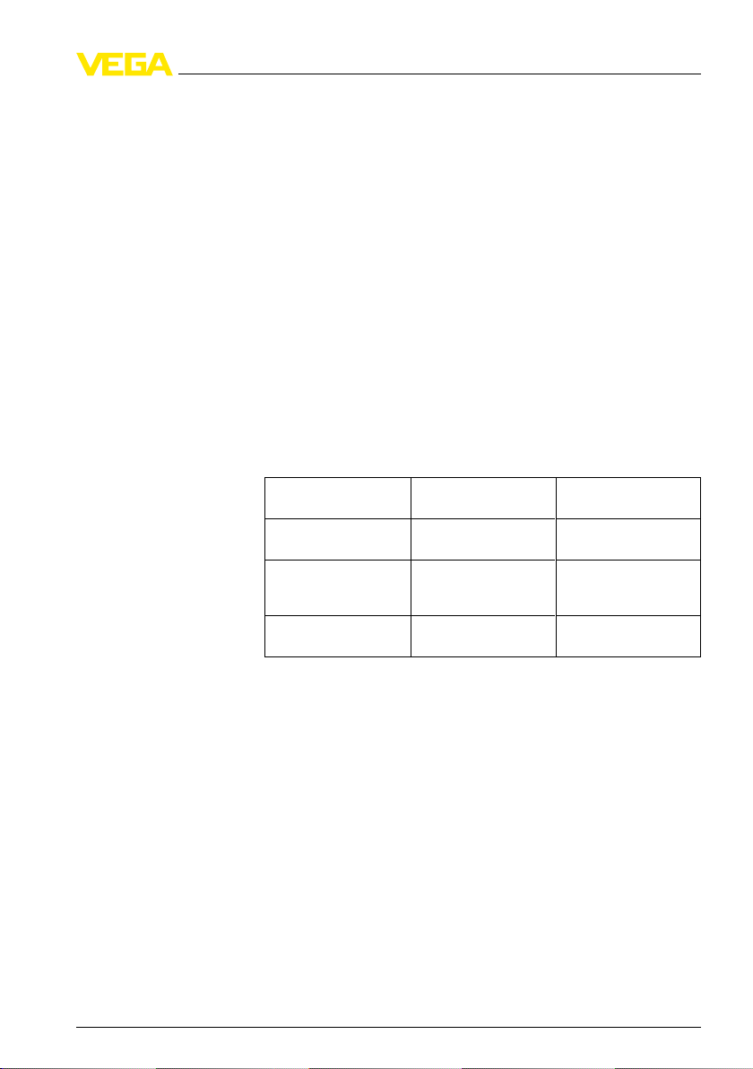
VEGAPULS 61, 62, 63, 65, 66, 67, 68
Valid hardware and software versions:
Serial number of the
electronics
VEGAPULS 61, 62, 63,
65, 66
VEGAPULS 61, 62, 63
with increased sensitivity
VEGAPULS 67, 68 > 14165303 from version 3.25 up to
> 13978716 from version 3.22 up to
> 14165303 from version 3.25 up to
Sensor software
version 3.80
version 3.80
version 3.80
Fault detection rate λ
96 %
36553-EN-100225
Recurring
function test • for VEGAPULS series 60 3
With this supplementary information you can carry out a recurring
function test of VEGAPULS series 60 level sensors without dismounting the instrument or moving the product level to the switching
point.
With this procedure, 88 % or 96 % of all dangerous undetected
instrument failures (λ
) are detected (DC
du
Proof
).
The described function test fulfils the requirements according to SIL.
If you have already created a sensor documentation during setup, you
du
can check the sensor at a detection rate of 96 % of all dangerous
undetected failures.
The remaining dangerous undetected failures are 11 FIT.
9
FIT = Failure In Time (1 FIT = 1 failure/10
h)
Page 4
1 A bou
t this document
Make sure that also a later sensor documentation is possible. This
sensor documentation of a recurring function test must be at least 6
months old.
Fault detection rate λ
88 %
If you created no sensor documentation during setup, you can check
du
the sensor only at a detection rate of 88 % of all dangerous undetected
failures.
The remaining dangerous undetected failures are in this case 32 FIT.
9
FIT = Failure In Time (1 FIT = 1 failure/10
Ple
ase note the Ex-specific safety information for installation and
h)
operation in Ex areas. These safety instructions are part of the scope
of delivery and come with the Ex-approved instruments.
War
ning:
The recurring function test influences connected devices. Take note
that downstream devices may be activated during the test.
Informa
tion:
Proceed according to the specified, recommended sequence of these
instructions to isolate possible device failures systematically.
Informa
tion:
Document the recurring function test, for example, in the test protocol
in the supplement. To facilitate the recording and for further function
tests, we recommend to copy the empty test protocol before
completing it.
This supplementary information manual can be downloaded from our
download section.
e recurring function test cannot replace the prescribed test
Th
according to WHG (Water Resources Act).
4 Recurring
36553-EN-100225
function test • for VEGAPULS series 60
Page 5
2 Prer
equisites
2 Prere
quisites
2.1 Authorised personnel
All operations described in this operating instructions manual must be
carried out only by trained specialist personnel authorised by the plant
operator.
During work on and with the device the required personal protective
equipment must always be worn.
2.2 Required tools
l This test instruction
l PACTware
l Actual VEGA DTM Collection
l Device-DTM of the corresponding sensor (part of the VEGA DTM
Collection)
l Communication-DTM (part of the VEGA DTM Collection)
l Interface adapter VEGACONNECT
l mA-meter or PLC resp. DCS (accuracy ≤±0.2 %)
l Operating instructions manual of the sensor
l Safety Manual
2.3 Required comparative data
The setup data should be used for verification of the settings.
The following setup data are required:
l Sensor documentation of the setup with all parameters or a sensor
documentation created at least 6 months ago
l Documentation of all parameter changes since the setup
36553-EN-100225
Recurring
the sensor documentation of the setup or a sensor documentation
If
created at least 6 months ago is not available, then the described
recurring function test (λ
96 %) cannot be carried out completely. In
du
this case, only the test at a detection rate of 88 % of all dangerous,
undetected failures is possible.
2.4 Required plant situation
Caution:
e sure that there are no considerable process-relating changes in
Mak
your plant during the recurring function test. This means also that the
level in the vessel should not change significantly by filling or emptying
during the test. Make sure that also temperature changes, stirrers,
current reactions in the vessel, etc. can cause level changes.
function test • for VEGAPULS series 60 5
Page 6
0
dB
1
2
2 P rereq
uisites
tion:
Informa
Document the recurring function test, for example, in the test protocol
in the supplement.
The following conditions must be fulfilled when performing the
recurring function test:
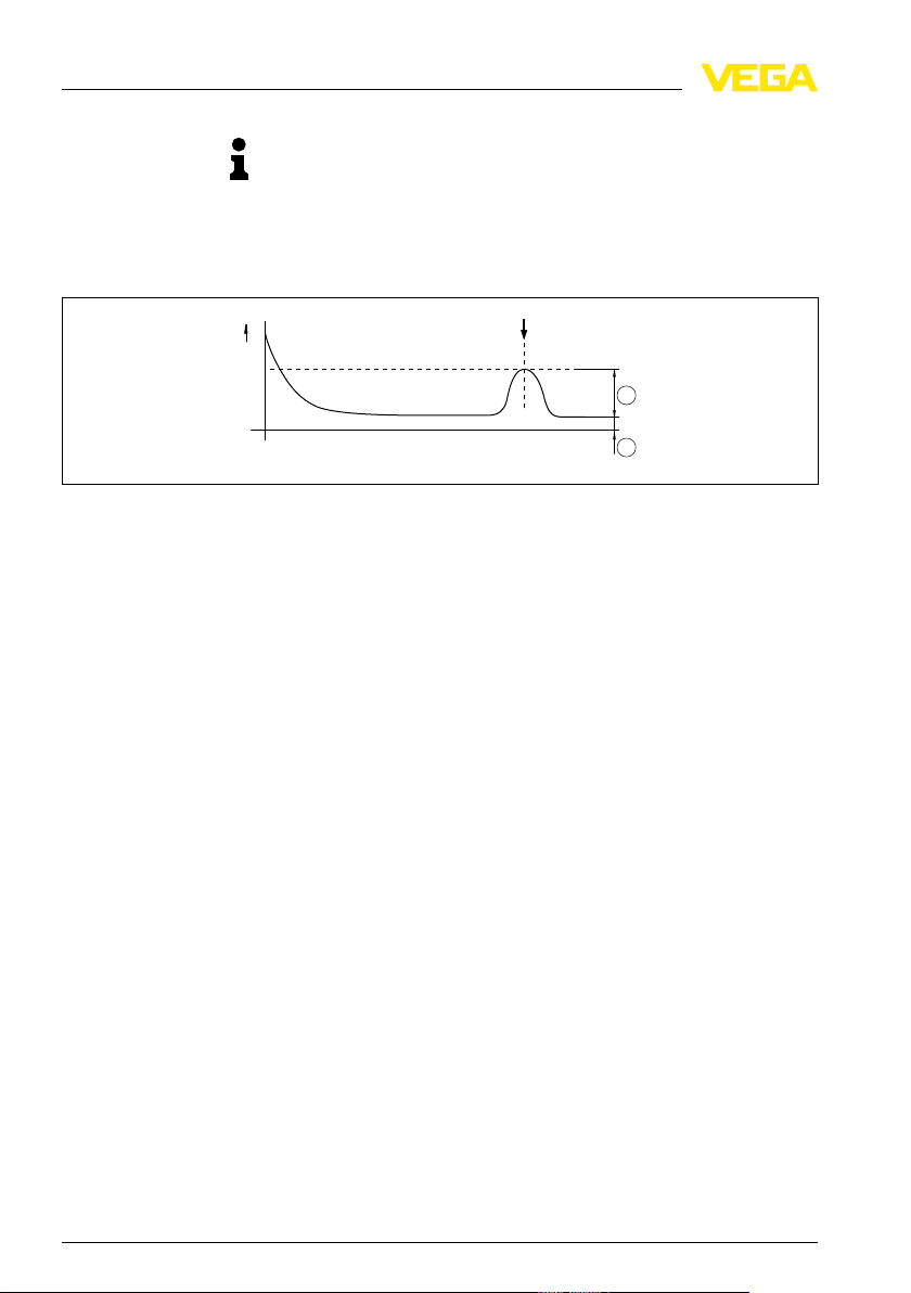
Fig. 1: Level
1 Amplitude of the useful echo above the noise level (signal/noise ratio)
2 Noise level
echo - VEGAPULS
l The level must be in the following areas:
- Min. distance to the level: Lower antenna edge +200 mm
- Level above the vessel bottom ≥ 250 mm
- Reliability at least 20 dB (amplitude of the useful logarithmic
echo above the noise level). The reliability can be verified
during the test.
l The process conditions must be nearly constant (level, process
pressure, process temperature).
l The medium must be the same as during setup or the medium
must at least belong to the same product group
- Solvents/Liquid gases/Hydrocarbons/Oils (DK value < 3)
- Chemical mixtures (DK value 3 … 10)
- Water/Acids/Bases (DK value > 10 or conductive)
36553-EN-100225
6 Recurring
function test • for VEGAPULS series 60
Page 7

ence of the recurring function test
3 Sequ
Function test not successful
3 Sequen
ce of the recurring function test
Carry out the recurring function test in the following sequence:
l 3.1 Restart the sensor
l 3.2 Verification of the current output
l 3.3 Verification of the instrument parameters (only with sensor
documentation)
l 3.4 Verification of the echo data (only with sensor documentation)
l 3.5 Sensor reaction to a level change
Informa
tion:
Document the recurring function test, for example, in the test protocol
in the supplement.
If one of the test points was not terminated successfully, there is
probably an undetected dangerous failure. The recurring function test
has failed.
In this case, proof of functional safety can only be provided by moving
the level to the switching point.
3.1 Restart of the sensor
With this test point, it is possible to check of the sensor ouputs the
same value within the prescribed min. accuravy after a restart.
ning:
War
The recurring function test influences connected devices. Take note
that downstream devices may be activated during the test.
Before the restart
36553-EN-100225
Recurring
function test • for VEGAPULS series 60 7
Carry out a restart of the sensor. Proceed as follows:
1 Start PACTware and the corresponding sens or DTM.
Make sure that the conditions to the plant situation are maintained.
See "Required plant situation".
(range of the actual level or the reliability at least 20 dB)
2 Set the indication to "Current".
3 The level is subject to plant or process-relevant fluctuations.
Control the indicated current values over an adequate period.
Make sure that a damping is probably adjusted on the sensor.
4 Note the upper and lower limit values of the measured value.
5 Measure the output current of the sensor.
Preferrably use the indication of the input current value in the
processing system.
Page 8

1
2
3
mA
3 Sequenc
e of the recurring function test
you do not have this possibility, connect an mA-meter according
If
to the following illustration.
You require the mA-meter for the verification of the current output
in the next test point. The accuracy of the mA-meter should be
better than 0.2 %. Select the smallest measuring range covering
4 … 20 mA.
After switching on again
Fig. 2: Connection
1 Level sensor
2 Processing system
3 mA-meter
6 Switch off the power supply.
7 Switch the voltage supply on again after approx. 10 s.
If the software signals a communication error during or after
switching off the power supply, you have to acknowledge it.
After connecting the sensor to power supply respectively after the
voltage recurrence, the instrument carries out a self-check for approx.
30 seconds:
l Internal check of the electronics
l The output signal jumps to the set error current
Then the current corresponding to the level is outputted to the cable.
1 The level is subject to plant or process-relevant fluctuations.
Control the indicated current values over an adequate period.
2 Note the upper and lower limit values of the measured value.
3 Compare the actually noted current values with the previously
noted values.
The two values must correspond within the safety accuracy of 2 %
(±0.32 mA).
If the two differential values are within the safety accuracy, then the
test of the restart was successful.
Continue with the next test point.
of the mA-meter
36553-EN-100225
8 Recurring
function test • for VEGAPULS series 60
Page 9

ence of the recurring function test
3 Sequ
Simulation 4 mA
Simulation 20 mA
3.2 Verificat
In this test point you simulate certain level values via the current
output. With this you can test the reaction of the sensor with different
current output values and the switching behaviour.
Warning:
The recurring function test influences connected devices. Take note
that downstream devices may be activated during the test.
1 Select in the DTM under the menu "Service" the menu item
"Simulation".
2 Select "Current" as measured variable for the simulation.
3 Activate the simulation.
4 Set the simulation value to 4 mA.
Take note that downstream devices may be activated.
5 Accept the simulation value.
Wait approx. 30 s.
The simulation is running and a corresponding current is being
outputted.
6 Note the displayed value (4 mA simulation) of the mA-meter.
The value must correspond with the simulated value within the
safety accuracy of 2 % (±0.32 mA).
Continue with the simulation if the two values correspond.
1 Set the simulation value of the current simulation to 20 mA.
Take note that downstream devices may be activated.
2 Accept the simulation value.
Wait approx. 30 s.
The simulation is running and a corresponding current is being
outputted.
3 Note the displayed value (20 mA simulation) of the mA-meter.
The value must correspond with the simulated value within the
safety accuracy of 2 % (±0.32 mA).
The verification of the current output was successful if the two values
correspond.
ion of the current output
36553-EN-100225
Recurring
Caution:
ate the simulation.
Deactiv
Continue with the next test point.
function test • for VEGAPULS series 60 9
Page 10

3 Sequenc
e of the recurring function test
Create a current sensor
documentation
3.3 Verificat
For this test point, the sensor documentation of the setup or the last
sensor documentation (at least 6 months old) is required. If a
parameter was changed since then, you also require the protocol or
the sensor documentation of this parameter change.
If this sensor documentation is not available, then the described
recurring function test cannot be carried out completely. In this case,
only the test with a detection rate of 88 % of all dangerous, undetected
failures is possible.
In this case, you continue with the test point "Sensor reaction on level
change" or create an actual sensor documentation and carry out the
function test after at least 6 months. The actual parameter adjustment
must be checked for correctness in the respect.
A sensor documentation was generated directly after the setup or at
least 6 months ago. For assessment of the instrument parameters, this
sensor documentation of the setup, the actual sensor documentation
of the last parameter change or the sensor documentation generation
and checked 6 months ago must be taken into consideration.
Create now a sensor documentation with the current instrument
parameters. Proceed as follows:
1 Select the function "Print" in the DTM.
2 For complete sensor documentation, you have to select all
instrument parameters (except laboratory parameters).
A multiple-page pdf documentation containing all relevant sensor
data is then generated.
3 Save this documentation as pdf document and, where appropriate,
print out the documentation to be on the safe side.
4 Compare the instrument parameters of this actual sensor
documentation with the sensor documentation of the setup or the
last parameter change.
Deviating parameters must be documented, justified and checked
on correctness.
If the actual sensor documentation corresponds to the stored sensor
documentation or if the modified parameters are correct, then the
verification of the instrument parameters was successful.
Continue with the next test point.
ion of the instrument parameters
36553-EN-100225
10 Recurring
function test • for VEGAPULS series 60
Page 11

ence of the recurring function test
3 Sequ
Calculation of the correction factor
3.4 Verificat
ion of echo data
For this test point, you require the sensor documentation of the setup
or a sensor documentation created at least 6 months ago.
If none of these sensor documentations is available, the described
recurring function test (λ
96 %) cannot be carried out.
du
Only the test at a detection rate of 88 % of all dangerous undetected
failures is possible. In this case, just skip this test point.
In this case, continue with the test point "Sensor reaction on level
change".
Use the two pdf files of the sensor documentation again for
assessment of the level echo.
Under chapter "Echo curve" you will find a short chart containing the
"Echo data". The data of this chart are relevant for the assessment.
Compare the values of the two echo data charts. The echo curve itself
cannot be compared.
Proceed as follows:
1 Compare the distance [m] of the two level echoes (actual/setup).
2 Divide the distance [m] of the current level through the distance [m]
of the level echo during setup.
Round this ratio "V" mathematically to one decimal point.
3 Search in the following chart the correction value (dB) belonging to
the calculated ration "V".
4 Calculate with the correction value the corrected value of the
amplitude.
This corrected value of the amplitude [dB] of the actual level echo
can be higher, but only max. 6 dB lower than the amplitude of the
level echo during setup.
36553-EN-100225
Recurring
Ratio "V" Correction value (dB)
0.5 -6
0.6 -4.5
0.7 -3
0.8 -2
0.9 -1
1.0 -0
function test • for VEGAPULS series 60 11
Page 12

3 Sequenc
e of the recurring function test
Ratio "V" Correction
1.1 +0.8
1.2 +1.5
1.3 +2.3
1.4 +3
1.5 +3.5
1.6 +4
1.7 +4.6
1.8 +5
1.9 +5.6
2.0 +6
value (dB)
Example
During setup, the level echo had 32 dB. The distance [m] to the
medium was 12.9 m.
The actual level echo has 25 dB. The distance [m] to the medium is
15.8 m.
Division of the current distance [m] by the distance [m] during setup:
15.8 m : 12.9 m = 1.224
Round mathematically to one position after the decimal point: 1.224 -->
1.2
Correction value for the ratio (1.2): + 1.5
Calculation of thecorrectedvalueoftheamplitude:25 dB + 1.5 = 26.5 dB
The result of the example (26.5 dB) is thus within the permissible
tolerance range of - 6 dB (32 dB - 6 dB = 26 dB)
In this example, the test point would be successfully fulfilled.
The following criteria must correspond when comparing the echo data:
l If there are false echoes in front of the level echo (highest useful
echo probability), they must have a useful echo probability of 0 %.
l The amplitude [dB] (with correction factor) of the actual level echo
(highest useful echo probability) corresponds to the respective
value of the level echo from the setup (tolerance max. -6 dB). This
means that the actual level echo can be higher, but only max. 6 dB
lower than the level echo during setup.
12 Recurring
36553-EN-100225
function test • for VEGAPULS series 60
Page 13

ence of the recurring function test
3 Sequ
all the above conditions are fulfilled, the measurement works
If
correctly and the verification of the echo data was successful.
Continue with the next test point.
3.5 Sensor reaction to a level change
With this test point, you monitor the reaction of the sensor during a
level change.
1 Set the indication of the sensor DTM to "Distance".
2 Change the filling of your vessel.
It doesn't matter if you fill or empty the vessel.
The filling speed is also not relevant.
The level change must be at least 50 mm.
3 Take note of the sensor reaction.
Does the measured value [m(d)] move in the correct direction
during emptying/filling?
The displayed measured value (distance) is the distance between
seal surface of the sensor and the product surface.
● The measured value will decrease during filling.
● The measured value will increase during emptying.
When the level value changes analogue to the level change, the
measurement works correctly and the assessment of the sensor
reaction was successful.
If all function tests were successful, the recurring function test is
finished.
36553-EN-100225
Recurring
you used an mA-meter for the recurring function test, switch off the
If
sensor and remove the mA-meter from the sensor cable after finishing
the recurring function test.
function test • for VEGAPULS series 60 13
Page 14

3 Sequenc
e of the recurring function test
Function test successful
Function test not suc-
cessful
3.6 Res
ult of the recurring function test
If all test points could be terminated successfully, then the recurring
function test was successful.
Fulfilled test points
3.1 / 3.2 / 3.3 / 3.4 / 3.5 Fault detection rate λ
3.1 / 3.2 / 3.5 (sensor documentation
of the setup or a sensor documentation which is at least 6 months old, is
not available)
Fault detection rate λdu88 %
du
96 %
The test must be repeated in regular intervals. The time periods
depend on the PFD
value according to the sepcifications in the
avg
Safety Manual (SIL).
If one of the test points (3.1 / 3.2 / 3.5) could not be terminated
successfully, there is probably an undetected dangerous failure. The
recurring function test has failed.
In this case, proof of functional safety can only be provided by moving
the level to the switching point.
14 Recurring
36553-EN-100225
function test • for VEGAPULS series 60
Page 15

est protocol - Recurring function test
4 T
4 Test
protocol - Recurring function test
If you copy this protocol, please note the date of the function test, the
measurement loop and the sensor serial number on each page.
Specifications VEGAPULS
Tester
Measurement loop name (sensor-TAG)
Sensor type
Serial number of the sensor
Software version
Required plant situation (according to chapter 2.4) □ maintained
Safety-instrumented system (SIS) □ yes
SIL activated □ yes
Medium or product group
Date of the setup (sensor documentation)
Date of the last function test (if carried out)
Test 3.1 - Restart of the sensor
Measured value before switching off Current value min. in mA Current value max. in mA
Measured value after switching on
again
Difference of the current values Current value min. in mA Current value max. in mA
Duration of the inspection in s
Test result
Min. and max. values
Current value min. in mA Current value max. in mA
□ Deviation ≤ 2 %
(test point successful)
□ Deviation > 2 %
(test point not successful)
Test 3.2 - Verification of the current output
Lower simulation value (4 mA) Indication mA-meter in mA
Intermediate result ≤ 2 % (≤0.32 mA) □ Corresponds □ Does not correspond
Upper simulation value (20 mA) Indication mA-meter in mA
Intermediate result ≤ 2 % (≤0.32 mA) □ Corresponds □ Does not correspond
Test result - Total □ Corresponds □ Does not correspond
36553-EN-100225
Recurring
function test • for VEGAPULS series 60 15
Page 16

est protocol - Recurring function test
4 T
□ Sensor
setup available
or
□ Sensor documentation (at least 6
months old) is available
documentation of the
File name:
□ Parameters correspond
□ Parameters do not correspond -
however checked on correctness
□ Parameters do not correspond -
File name:
File name:
deviation not acceptable
□ Sensor documentation of the
setup not available
□ Parameters checked on correct-
ness and saved (recheck after 6
File name:
months necessary)
Test result □ All parameters correct or
□ Parameters not correct
checked on correctness
Tester:
Test 3.4 - Verification of the echo data
No false echoes or echoes with
□ Corresponds □ Does not correspond
useful echo probability 0 %
Corresponding amplitude □ In the tolerance range □ Not in the tolerance range
Test result □ Corresponds □ Does not correspond
Test 3.5 - Verification of the sensor reaction
Reduction of the level □ Distance value [m] increases □ Other reaction
Increase of the level □ Distance value [m] decreases □ Other reaction
Test result □ Corresponding sensor reaction □ Sensor reaction does not corre-
spond
● Summary 96 % (λ
)
du
Date Signature
Test 3.1 / 3.2 / 3.3 / 3.4 / 3.5 □ All five test points passed □ One or several test points did not
pass
● Summary 88 % (λ
)
du
Date Signature
16 Recurring
function test • for VEGAPULS series 60
36553-EN-100225
Page 17

est protocol - Recurring function test
4 T
● Summary 88 % (λ
Test 3.1 / 3.2 / 3.5 □ All three test points passed □ One or several test points did not
)
du
pass
Date ___________________________________
Signature ___________________________________
36553-EN-100225
Recurring
function test • for VEGAPULS series 60 17
Page 18

est protocol - Recurring function test
4 T
18 Recurring
36553-EN-100225
function test • for VEGAPULS series 60
Page 19

est protocol - Recurring function test
4 T
36553-EN-100225
Recurring
function test • for VEGAPULS series 60 19
Page 20

VEGA Grieshaber KG
ISO 9001
Am Hohenstein 113
77761 Schiltach
Germany
Phone +49 7836 50-0
Fax +49 7836 50-201
E-mail: info@de.vega.com
www.vega.com
Printing date:
statements concerning scope of delivery, application,
All
practical use and operating conditions of the sensors and
processing systems correspond to the information avail-
able at the time of printing.
© VEGA Grieshaber KG, Schiltach/Germany 2010
Subject to change without prior notice 36553-EN-100225
 Loading...