

Page 1
Operating Instruction
VEGAPULS 56V
Level and Pressure
Page 2

Contents
Safety information ........................................................................ 2
Note Ex-area ................................................................................ 2
1 Product description
1.1 Function ................................................................................ 4
1.2 Application features ............................................................. 6
1.3 Adjustment ........................................................................... 7
1.4 Antennas ............................................................................... 9
2 Types and versions
2.1 Type survey ........................................................................ 10
2.2 Configuration of measuring systems ................................. 12
3 Technical data
3.1 Data .................................................................................... 19
3.2 Dimensions ......................................................................... 26
3.3 Approvals ........................................................................... 29
Contents
Safety information
The described module must only be installed
and operated as described in this operating
instruction. Please note that other action can
cause damage for which VEGA does not take
responsibility.
2 VEGAPULS 56V
Note Ex-area
Please note the attached approval documents
(yellow binder) and especially the included
safety data sheet.
Page 3

Contents
4 Mounting and installation
4.1 General installation instructions ......................................... 30
4.2 Measurement of liquids ...................................................... 32
4.3 Measurement in a standpipe (surge or bypass pipe)....... 33
4.4 False echoes ...................................................................... 40
4.5 Installation fault .................................................................. 42
5 Electrical connection
5.1 Connection and connection cable..................................... 44
5.2 Connection of the sensor ................................................... 44
5.3 Connection of the external indicating instrument
VEGADIS 50 ....................................................................... 47
6 Set-up
6.1 Adjustment structure .......................................................... 48
6.2 Adjustment with the PC on VEGAMET ............................... 49
6.3 Adjustment with MINICOM or VEGAMET .......................... 61
6.4 Adjustment with the PC on VEGALOG .............................. 74
VEGAPULS 56V 3
Page 4

1 Product description
Level measurement on high temperature
processes or on mediums with high temperature was formerly very difficult or even impossible. If in addition the measurement
should be made under high pressure, up to
now there was no measuring system available. Apart from a non-contact measurement
with good measuring accuracy.
In distillation and stripper columns, up to now
levels (e.g. of sump, plate and head products) could generally only be measured by
pressure sensors or differential pressure
measurements. The installation required for
such pressure measuring systems (pressure
lines, pressure transmitters…) is considerable and expensive, often amounting to several times the value of the sensor itself. Due
to missing of suitable alternatives, instrumentation departments have not only to arrange
with this fact but also with high maintenance
costs (cleaning of measuring pipes, errors
by condensation, build-up on the diaphragm…) and often had to accept inadequate accuracy (temperature errors, density fluctuations, installation faults …).
The requirements of the petrochemical industry for a non-contact level sensor are the
following:
• independent of temperature and pressure
• process temperature up to 350°C
• process pressure up to 64␣ bar
• high resistance wetted parts for universal
use
• accuracy 0,1␣ %
• rugged metal housing
• Ex-approved (available in EEx d and
EEx ia)
• Loop-powered as well as digitally connectable
Product description
Sensors which would not have been possible
without the new results in the material and
production technology. An especially developed ceramics is used as coupling material.
This ceramic is chemically and thermically
very high resistant.
The sensor materials in contact with the process are all highly resistant. This refers not so
much to the flange material of high-alloy
stainless steel (1.4571 or superior), as to the
specially developed ceramic (Al2O3) and its
gland. The ceramic rod receives from the
high frequency module the radar signals and
the cone-shaped end works as emitter and
receiver. The seal between stainless steel
flange and ceramic rod is made with a Tantalum seal ring.
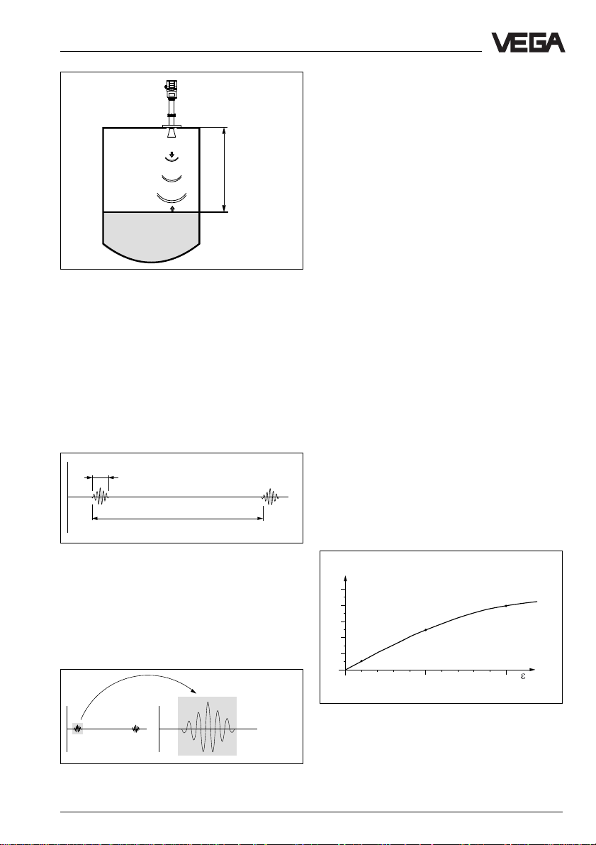
1.1 Function
Radio detecting and ranging: Radar.
VEGAPULS radar sensors are used for noncontact and continuous distance measurement. The measured distance corresponds
to a filling height and is provided as level.
Measuring principle:
emission – reflection – receipt
Smallest 5,8␣ GHz radar signals are emitted
from the antenna of the radar sensor as short
pulses. The radar impulses reflected by the
sensor environment and the product are
received by the antenna as radar echoes.
The running period of the radar impulses
from emission to receipt is proportional to the
distance and hence to the level.
This initial position defines the development
aims for a high-temperature radar level
measuring system of VEGAPULS 56 series.
A special new development of high-temperature radar sensors for level measurement in
temperatures up to 350°C and pressures up
to 64␣ bar.
4 VEGAPULS 56V
Page 5
Product description
Meas. distance
emission - reflection - receipt
The radar impulses are emitted by the antenna system as impulse packets with a
pulse duration of 1 ns and pulse breaks of
278 ns; this corresponds to a pulse package
frequency of 3,6␣ MHz. In the impulse breaks
the antenna system operates as receiver.
Signal running periods of less than one millionth of a second must be processed and
the echo pictures must be evaluated in a
fraction of a second.
1 ns
Hence it is possible for the VEGAPULS 56
radar sensors to process the slow-motion
pictures of the sensor environment precisely
and in detail in cycles of 0,5 up to 1 second
without using very time consuming frequency
analysis (e.g. FMCW) necessary for other
radar principles.
Virtually all products can be measured
Radar signals physically react similar to visible light. According to the quantum theory
they penetrate empty space. Hence they are
not bound such as e.g. sound to a conductive product (air) and spread like with light
velocity. The radar signals react to two electrical primary quantities:
- the electrical conductivity of a substance.
- the dielectric constant of a substance.
All products which are electrically conductive
reflect radar signals very well. Even only
slightly conductive products ensure a sufficient signal reflection for a reliable measurement.
All products with a dielectric constant ε
more than 2,0 reflect radar impulses sufficiently (note: air has a dielectric constant
figure ε
of 1).
r
of
r
278 ns
Pulse sequence
%
VEGAPULS radar sensors can reach this in a
special procedure of time transformation
which spreads more than 3,6 million echo
pictures per second in a slow motion picture,
then freezes and processes them.
50
40
30
20
10
5 %
5
0
2
0
25 %
4 6 8 12 14 16 18
10
40 %
20
r
Reflected radar power dependent on the dielectric
t
t
constant figure of the measured product
Time transformation
VEGAPULS 56V 5
Page 6
Product description
The signal reflection increases with the conductivity or with the dielectric constant of the
medium. Hence virtually all mediums can be
measured.
Due to standard flanges from DN 50 to
DN 250, ANSI 2“ to ANSI 10“ the sensor
antenna systems are adapted to the various
measured products and process environments. High-quality materials withstand also
extremely chemical and physical conditions.
The sensors deliver reliable, precise and
longterm stable, reproducible analogue or
digital level signals.
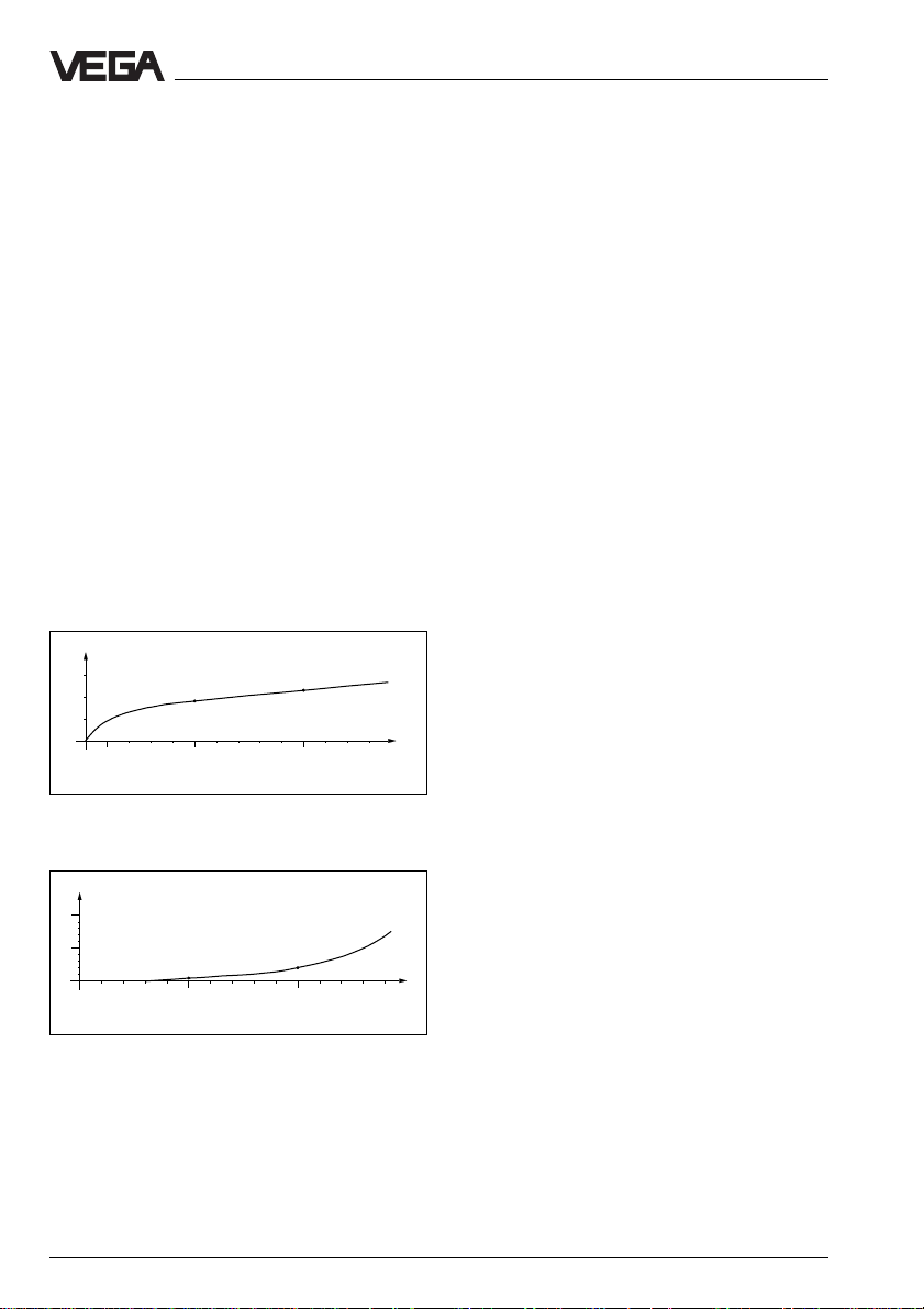
Continuous and reliable
Unaffected by temperature, pressure and
atmosphere type, VEGAPULS radar sensors
detect quickly and precise levels of different
mediums.
%
0,03
0,02
0,01
0
100 500 1000 1300 ˚C
0
0,018 %
Temperature influence:
Temperature error absolutely zero (e.g. at 500°C
0,018 %)
%
10
5
0
10
0
0,8 %
20 30 40 60
50
0,023 %
3 %
70 80 90 110 120 130 140
100
bar
1.2 Application features
Applications
• level measurement of liquids and solids
• measurement also in vacuum
• all slightly conductive materials and sub-
stances with a dielectric constant ε
can be measured
• measuring ranges 0 … 20 m
Two-wire technology
• supply and output signal on one two-wire
line
• digital output signal
Rugged and abrasion proof
• non-contact
• high resistance materials
Exact and reliable
• resolution 1 mm
• unaffected by noise, vapours, dusts, gas
compositions and inert gas layering
• unaffected by varying density and temperature of the medium
• measurement with pressures up to 64 bar
and medium temperatures up to 350°C
Communicative
• individually connectable, with 15 sensors
on one two-wire line (digital output signal)
• integral measured value indication
• optionally indication up to 25 m separated
from the sensor
• connection to all BUS-systems: Interbus␣ S,
Modbus, Siemens 3964R, Profibus DP,
Profibus FMS, ASCII
• Adjustment from the DCS-stage
Ex-approvals
• CENELEC, FM, ABS, LRS, GL, LR, ATEX,
PTB, FCC
> 2,0
r
Pressure influence:
Error with pressure increase very low (e.g. at 50␣ bar
0,8 %)
VEGAPULS 56 enable level measurements
where radar sensors could not be used
before.
6 VEGAPULS 56V
Page 7
Product description
1.3 Adjustment
Each measuring distance is different, hence
each radar sensor must be given some
basic information on the application and the
environment.
The adjustment and parameter adjustment of
the radar sensors are carried out with
- the PC
- the detachable adjustment module
MINICOM
- the signal conditioning instrument
VEGAMET
Adjustment with PC
The set-up and adjustment of the radar
sensors is generally made on the PC with the
adjustment program VVO (VEGA Visual
Operating) under Windows
The program leads quickly through the adjustment and parameter adjustment via pictures, graphics and process visualisations.
®
.
2
2
2
2
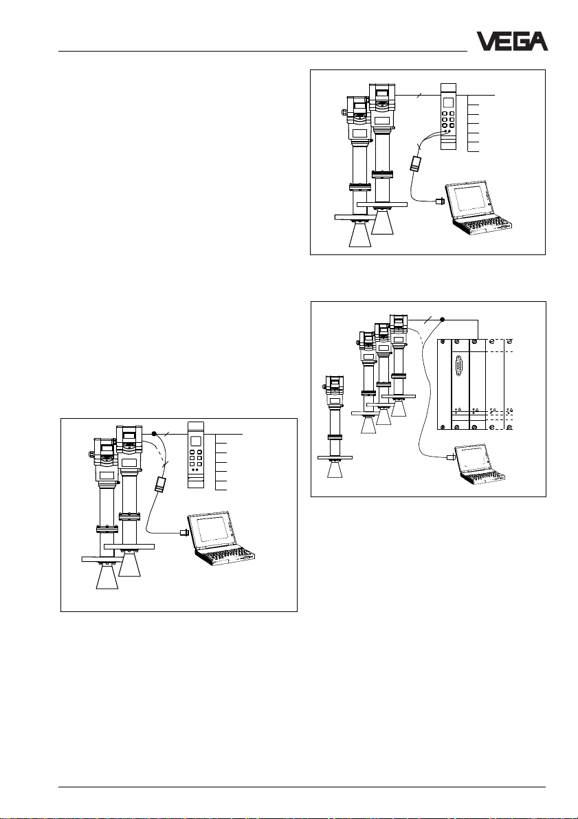
One or two sensors on the signal conditioning instrument; adjustment with the PC on the signal conditioning instrument
2
......
VEGALOG
VEGALOG
571 CPU
571 EA
1 ... 15
1␣ …␣ 15 sensors on the processing system VEGALOG. Adjustment with the PC on the digital signal and
supply line to the processing system or on the sensor directly
With the standard cable (RS␣ 232) the PC is
directly connected to the processing system
VEGALOG.
Adjustment with PC on the digital signal and supply
line between sensors and signal conditioning instrument VEGAMET
The adjustment and parameter adjustment
data can be saved with the adjustment soft-
ware on the PC and protected by passThe PC can be connected to any individual
position of the system or the signal line. It is
words. If required the adjustments can be
transmitted quickly to other sensors.
hence connected with the two-wire PC-interface converter VEGACONNECT␣ 2 to the sensor or to the signal line.
VEGAPULS 56V 7
Page 8
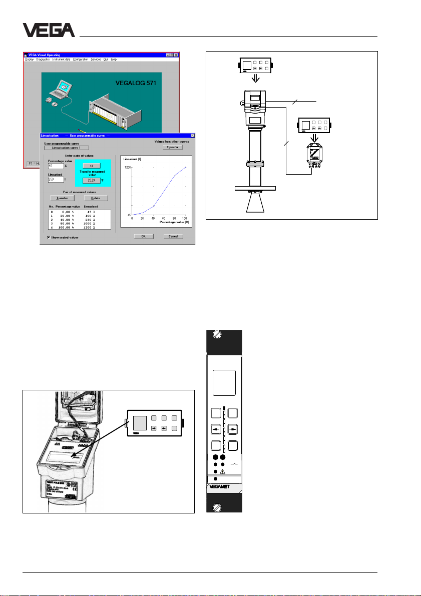
Automatic sensor determination (above figure) and
visualized adjustment, e.g. of a vessel linearisation
curve (bottom figure)
Product description
ESC
+
Tank 1
-
m (d)
12.345
OK
2
ESC
+
Tank 1
-
m (d)
12.345
OK
4
Adjustment with the detachable adjustment module on
the radar sensor or on the external indicating instrument VEGADIS 50
By removing the adjustment module unauthorized adjustments are avoided.
Adjustment with adjustment module
MINICOM
With the (3,2␣ cm␣ x␣ 6,7␣ cm) 6-key adjustment
module with display you can carry out the
adjustment in clear text. The adjustment module can be plugged into the radar sensor or
into the optional external indicating instrument.
Tank 1
m (d)
12.345
Detachable adjustment module MINICOM
ESC
+
-
OK
Adjustment with signal conditioning instrument VEGAMET
The radar sensors with digital
output signal can be adjusted
beside the PC also with the
signal conditioning instrument
VEGAMET.
For adjustment the digital signal
%
100
-
ESC
CONNECT
2
1
on
514 Ex
Signal conditioning instru-
conditioning instruments VEGAMET 514V and 515V are provided with a 6-key-adjustment
+
field with display. There the
parameter adjustment can be
carried out in clear text. The
OK
adjustment structure corresponds to the adjustment on
the adjustment module MINICOM.
ment VEGAMET with 6-key
adjustment field on the
instrument front
8 VEGAPULS 56V
Page 9
Product description
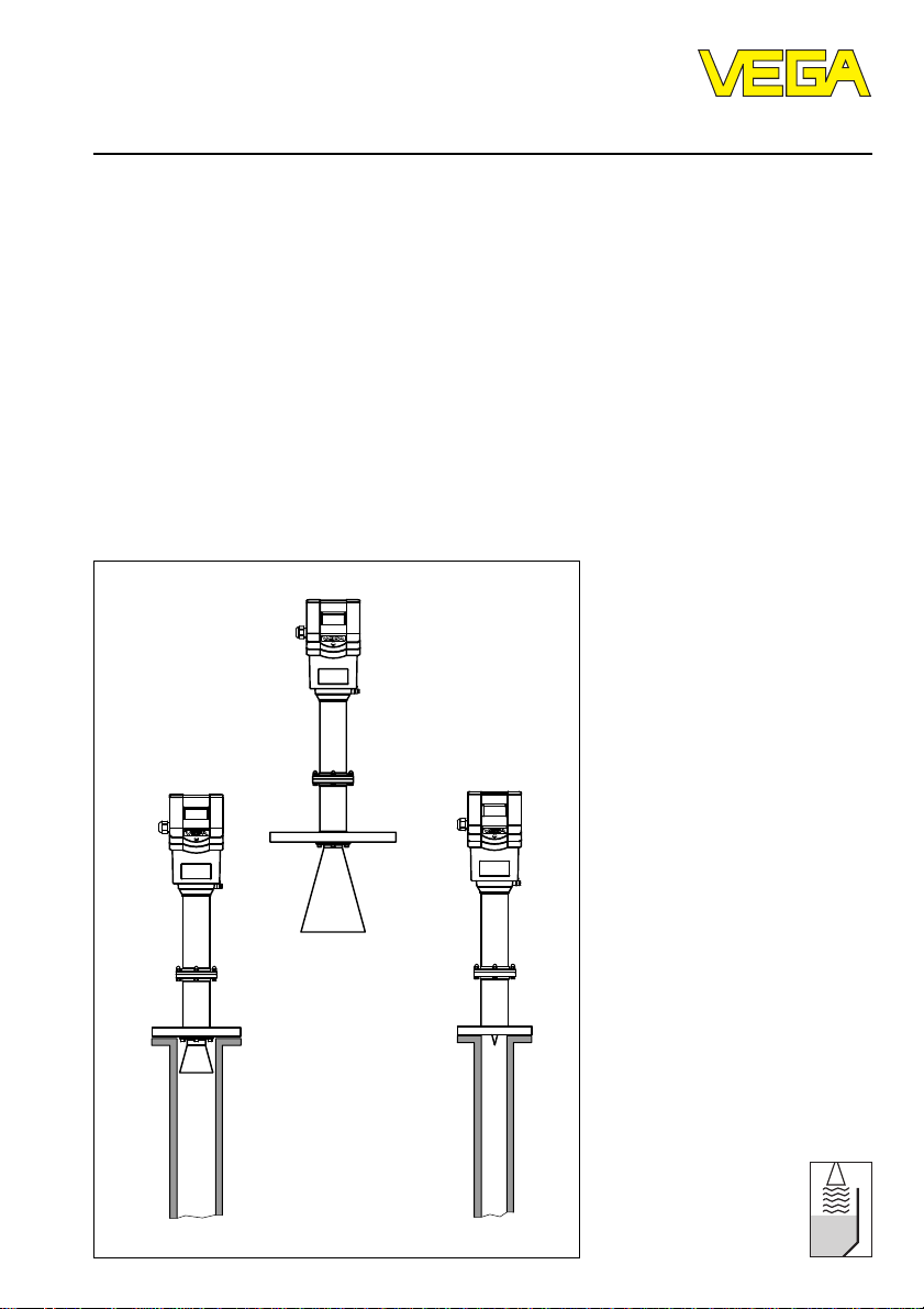
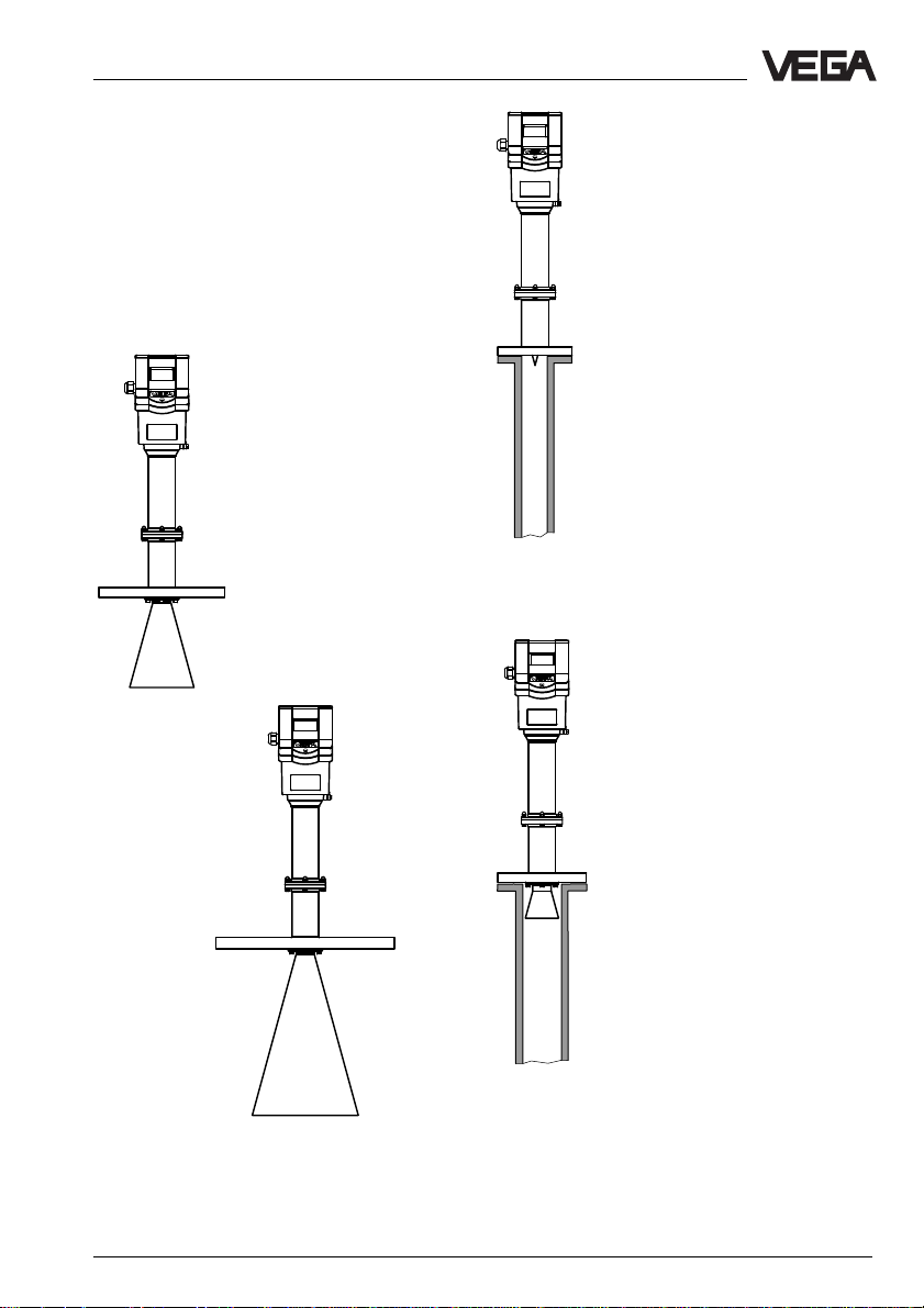
1.4 Antennas
The antenna is the eye of the radar sensor.
Various antenna configurations are available
for different applications and process conditions.
Horn antenna
Horn antennas focus the
radar signals very well.
Manufactured of 1.4571
(stst) or Hastelloy C22
they are very rugged and
physically as well as
chemically resistant. Horn
antennas are used for
measurement in closed or
open vessels.
DN 150
DN 50
Pipe antenna
Pipe antennas on surge or bypass pipes only form a complete
antenna system in conjunction
with a measuring pipe which can
also be bent. Pipe antennas are
best suited for products with
extreme product movements or
products with low dielectric
constant.
The antenna can be with or without horn. It characterizes by
very good antenna gain. A very
good antenna reliability can be
achieved even in case of products with very bad reflection
features.
The measuring pipe means a
conductor for radar signals. The
running period of the radar
signals changes in the pipe and
depends on the pipe diameter.
The pipe inner diameter must be
programmed in the electronics
so that the running period can
be compensated.
DN 80
DN 250
VEGAPULS 56V 9
Page 10
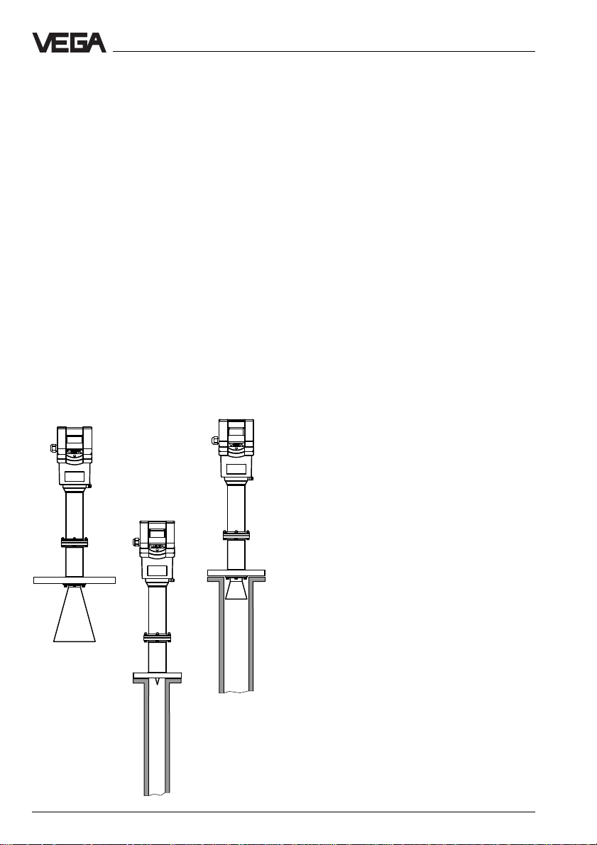
2 T ypes and versions
VEGAPULS 56 sensors are a new developed
generation of very compact high temperature
radar sensors. For the first time it is now
possible to carry out a non-contact level
measurement under high temperatures and
pressures. They open the advantages of a
radar level measurement for applications
where the special advantages of radar were
formerly not applicable due to the extreme
process conditions.
VEGAPULS 56 radar sensors dominate the
two-wire technology perfectly. They are the
first radar sensors transmitting the supply
voltage and the output signal via one twowire line. As output or measuring signal they
operate with an analogue 4␣ …␣ 20␣ mA-output
signal or with a digital output signal. This
operating instruction describes the sensors
with digital output signal.
VEGAPULS 56
DN 150
VEGAPULS 56
DN 50 pipe antenna
VEGAPULS 56
DN 80 pipe antenna
Types and versions
2.1 Type survey
General features
• level measurement on processes and
products under high temperatures and
high pressures
• measuring range 0 … 20 m
• Ex-approved in zone 1 and zone 10 (IEC)
or zone 0 and zone 20 (ATEX) classification
EEx␣ ia␣ IIC␣ T6 or EEx d ia IIC T6
• integral measured value indication
• external measured value indication which
can be mounted up to 25 m separated in
Ex-area
Survey of features
Signal output
- digital transmission of measuring signal to
a signal conditioning instrument VEGAMET
or the processing system VEGALOG
Voltage supply
– two-wire technology (voltage supply and
digital signal via one two-wire line)
Process connection
– DN 50; ANSI 2“
– DN 80; ANSI 3“
– DN 100; ANSI 4“
– DN 150; ANSI 6“
– DN 200; ANSI 8“
– DN 250; ANSI 10“
Adjustment
–PC
– adjustment module in the sensor
– adjustment module in external indicating
instrument
– VEGA-signal conditioning instrument
Antennas
– horn antenna with stainless steel horn and
ceramic tip
– standpipe antenna only with ceramic tip or
with small horn and ceramic tip
10 VEGAPULS 56V
Page 11
Types and versions
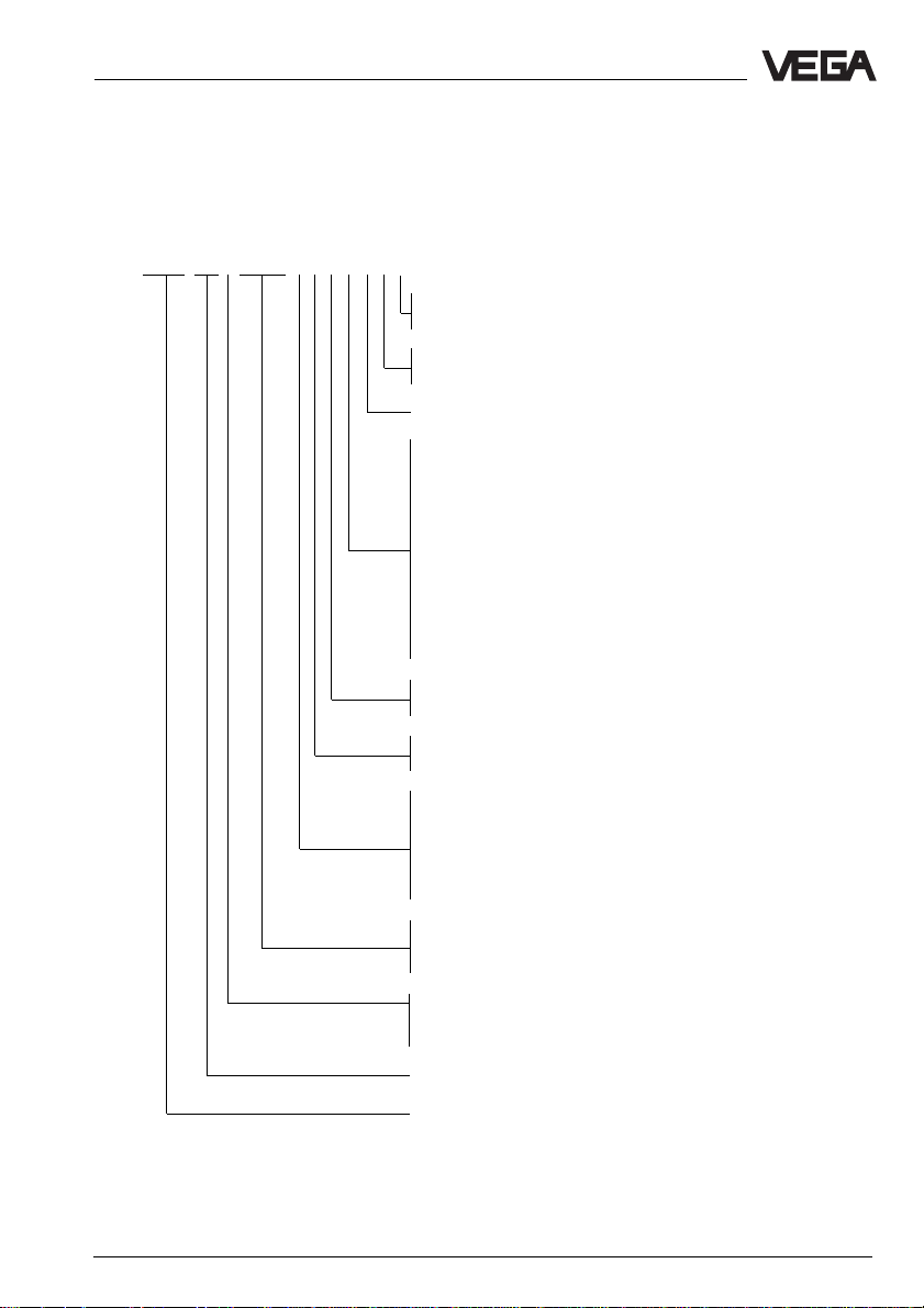
Type code
56… high temperature radar sensor
…K 4␣ …␣ 20␣ mA-output signal (not described in this operating instruction)
…V digital output signal
VEGAPULS 56 V EXXX X X X X X X X
J - Tube extension for horn antenna
X - without
A - Aluminium housing
D - Aluminium housing with Exd-connection housing
T - Seal of the antenna system of Tantalum
KVX - Process connection DN 50 PN 16 (for standpipe)
LV6 - Process connection DN 80 PN 16 (for standpipe)
EV1 - Process connection DN 100 PN 16 (for standpipe)
FV2 - Process connection DN 150 PN 16
SVX - Process connection ANSI 2“ 150 psi (for standpipe)
WV6 - Process connection ANSI 3“ 150 psi (for standpipe)
PV1 - Process connection ANSI 4“ 150 psi (for standpipe)
VV2 - Process connection ANSI 6“ 150 psi
0V2 - Process connection ANSI 6“ 300 psi
1V2 - Process connection ANSI 6“ 600 psi (1.4571)
1M2 - Process connection ANSI 6“ 600 psi (Hastelloy C22)
YYY - Other process connections and materials
X - without indication
A - with integral indication
X - without adjustment module MINICOM
B - with adjustment module MINICOM (pluggable)
B - 20␣ …␣ 72 V DC; 20 … 250 V AC; 4␣ …␣ 20␣ mA; HART
D - Two-wire (loop-powered); 4␣ …␣ 20␣ mA; HART
E - Supply via signal conditioning instrument
P - 90 … 250 V AC (only in USA)
N - 20 … 36 V DC, 24 V AC (only in USA)
Z - Supply via signal conditioning instrument (only in USA)
.X - FTZ approval (Germany)
EX.X - approved for zone 1 and zone 10
EX0.X - E x approved zone 0
K - Analogue 4 … 20 mA output signal
(two-wire technology)
V - Digital output signal (two-wire technology)
Instrument series for high temperature applications
Measuring principle (PULS for radar)
®
®
VEGAPULS 56V 11
Page 12

Types and versions
2.2 Configuration of measuring systems
A measuring system consists of a sensor
and a processing unit. The processing unit
(the signal conditioning instrument VEGAMET
or the processing system VEGALOG) processes the level proportional digital measuring
signal in a number of processing routines
and provides then the levels as individual
current, voltage or switching signals.
On the signal conditioning instrument VEGAMET 515V two sensors can be connected via
one two-wire line. On the processing system
VEGALOG 571 up to 255 sensors can be
connected; 15 sensors (loop powered) on
one two-wire line.
Beside the output of the levels in percent,
cubic metres or other physical units, as current, voltage or switching signal (relay or
transistor) the levels can also be processed
via combined processing algorithms. Scaling, linearisation, calculation of linearisation
curves, differential generation, addition or
tendency processing are fixed implemented
in the processing systems VEGALOG and
VEGAMET as processing routines and easily
available via menu choice.
On the following pages you will see different
instrument configurations, called measuring
systems:
• 2 sensors on one two-wire line;
• 2 sensors in Ex-area on one two-wire line;
(page 14)
• 15 sensors on one two-wire line;
• 5 sensors in Ex-area on one two-wire line;
(page 16)
(page 13)
(page 15)
Ex-area
The sensors with classification EEx␣ ia require
for operation in Ex-areas the Ex-separator
VEGATRENN 548V␣ Ex, providing intrinsically
safe Ex-circuits to the sensors. The sensors
with classification EEx␣ d␣ ia are provided with
a pressure tight encapsulated connection
box. This converts a non-intrinsically safe
supply circuit into an intrinsically safe circuit.
Up to 15 sensors in groups with five sensors
each per two-wire line can be connected to
Ex-separator VEGATRENN 548V␣ Ex
17)
.
Note!
In Ex-systems earthing on both sides is not
allowed due to the potential difference.
Note:
Sensor lines should be looped in screened
cables. It is suitable (except Ex-systems) to
earth the cable screens on both ends. Therefore it must be noted that no earth compensation currents flow via the screens. In case
of earthing on both sides earth compensation
currents are avoided by connecting the cable
screen on one earth side (e.g. in the switching cabinet) via a capacitor (e.g. 0,1␣ µF;
250␣ V) to the earth potential.
Sensor lines leading to the same input card
or separator card can be looped together in
a screened multiple wire cable. Sensor lines
leading to other separator cards must be
looped in separated screened cables.
(page
12 VEGAPULS 56V
Page 13
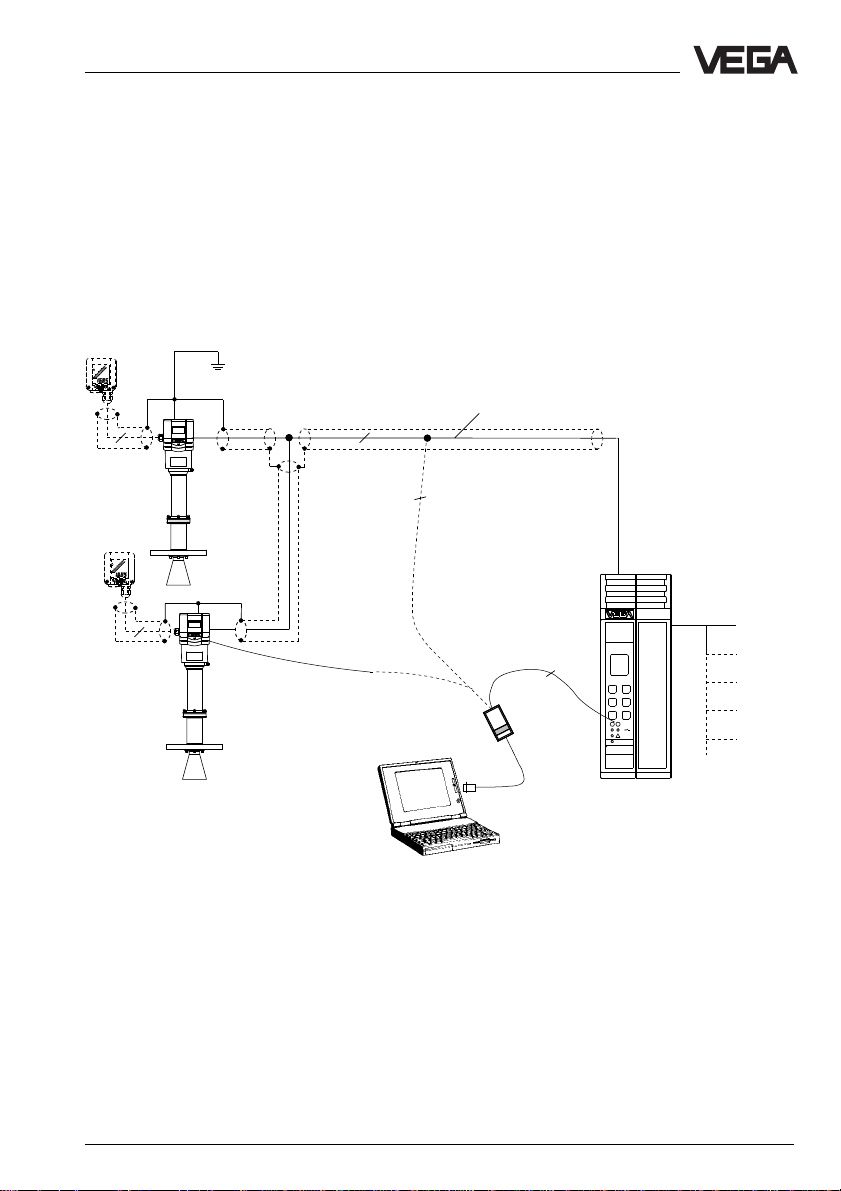
Types and versions
Measuring system with 1 … 2 VEGAPULS 56V on signal conditioning instrument
VEGAMET 515V
• Two-wire technology, supply from the signal conditioning instrument; output signals and
voltage supply via one two-wire line
• Digital output signal, two sensors on one line
• Measured value indication in the sensor and in the signal conditioning instrument
• Optionally external indicating instrument (can be mounted up to 25 m separated from the
sensor in Ex-area)
• Adjustment with PC, signal conditioning instrument or adjustment module MINICOM (can be
plugged into the sensor or into the external indicating instrument VEGADIS 50)
• Max. resistance of the signal line 15 Ω per wire or 1000␣ m cable length
VEGADIS 50
4
VEGADIS 50
Screened line in case of electromagnetic interferences
1)
2
2
Current outputs
Voltage outputs
Relays
Digital
connectability
Fault signals
4
2
VEGACONNECT 2
1)
Sensor lines should be looped in screened cables.
VEGAMET
515V
Signal conditioning
instrument VEGAMET
515V in housing type 505
Earth the cable screens on the processing system
or better on the sensor. In case of stronger
electromagnetic interferences it is useful to earth
the cable screens on both ends. However it must
be noted that no earth compensation currents flow
via the screens. In case of earthing on both sides
earth compensation currents are avoided by
connecting the cable screen on one earth side
(e.g. in the switching cabinet) via a capacitor (e.g.
0,1␣ µF; 250␣ V) to the earth potential.
VEGAPULS 56V 13
Page 14
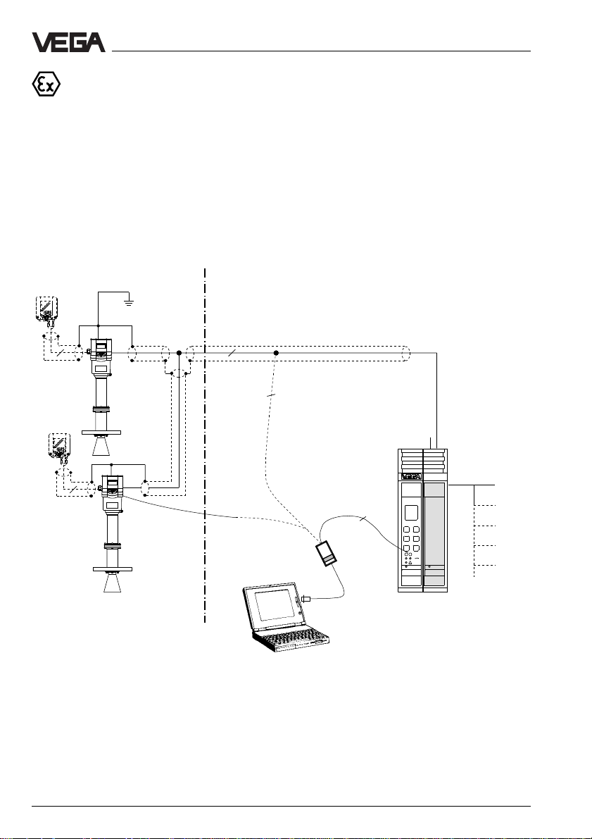
Types and versions
Measuring system with 1 … 2 VEGAPULS 56V Ex, 56V Ex0 via a separator
VEGATRENN 548V Ex on the signal conditioning instrument VEGAMET 515V
• Two-wire technology, intrinsically safe ia-supply from the separator, for operation in Ex
zone 1 (VEGAPULS 56V␣ Ex) or Ex zone 0 applications (VEGAPULS 56V␣ Ex0)
• Ex-area according to CENELEC and ATEX
• Digital output signal, two sensors on one line
• Optionally external indicating instrument with analogue and digital indication (can be
mounted up to 25 m separated from the sensor)
• Adjustment with PC, signal conditioning instrument or adjustment module MINICOM (can be
plugged into the sensor or into the external indicating instrument VEGADIS 50)
• Max. resistance of the signal line 15 Ω per wire or 1000␣ m cable length (see also approval
certificate of the separators)
VEGADIS 50
EEx ia
4
VEGADIS 50
Ex-area Non-Ex-area
EEx ia
2
4
VEGACONNECT 2
1)
Sensor lines should be looped in screened cables.
Earth the cable screens on the processing system
or better on the sensor. In case of stronger
electromagnetic interferences it is useful to earth
the cable screens on both ends. However it must
be noted that no earth compensation currents flow
via the screens. In case of earthing on both sides
earth compensation currents are avoided by
connecting the cable screen on one earth side
(e.g. in the switching cabinet) via a capacitor (e.g.
0,1␣ µF; 250␣ V) to the earth potential.
Screened line in case of electromagnetic interferences
1)
2
Current outputs
Voltage outputs
Relays
Digital
connectability
Fault signals
2
VEGAMET
VEGATRENN
515V
547
Signal conditioning instrument VEGAMET 515V with
Ex-separator VEGATRENN
548V␣ Ex in housing type 506
Note!
In Ex-systems earthing on both sides is not
allowed due to the potential difference.
14 VEGAPULS 56V
Page 15
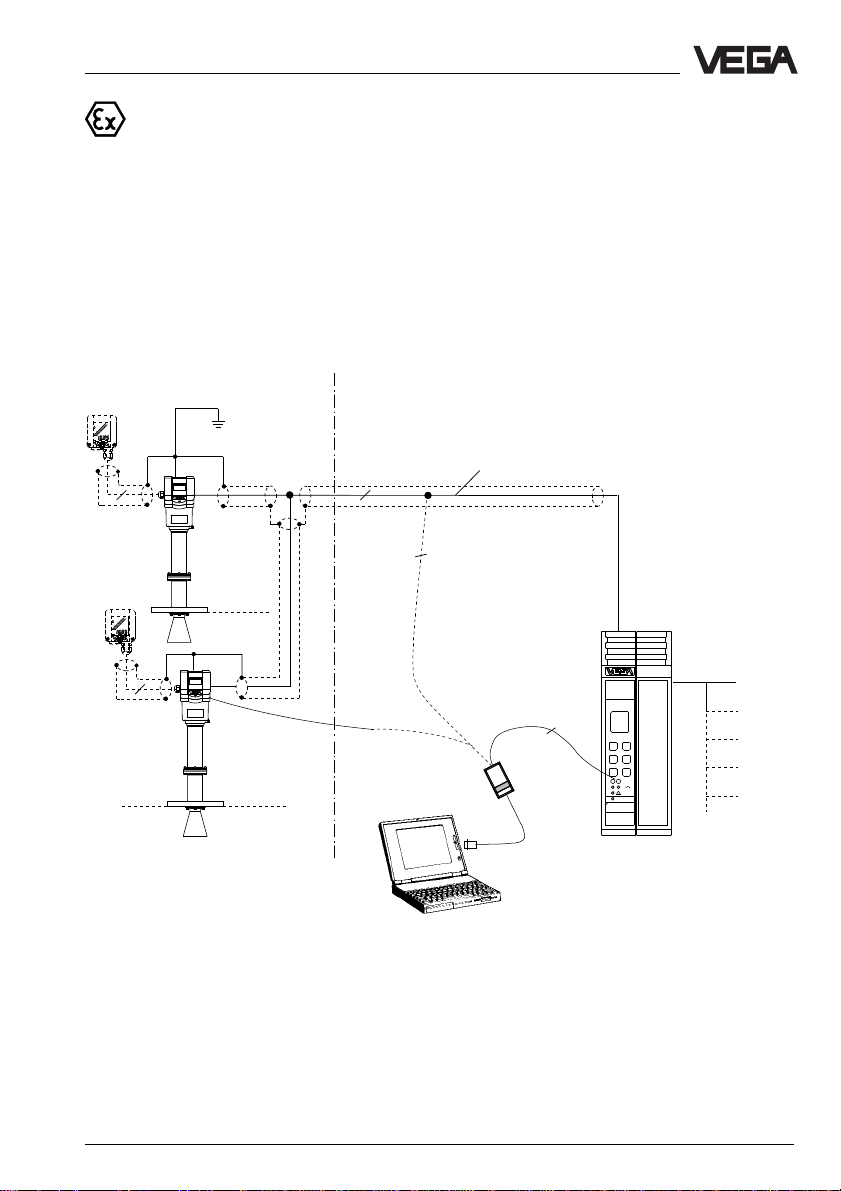
Types and versions
Measuring system with 1 … 2 VEGAPULS 56V Ex, 56V Ex0 with pressure
tight encapsulated connection box on the signal conditioning instrument
VEGAMET 515V
• Two-wire technology, supply from the signal conditioning instrument for operation in Ex
zone 1 (VEGAPULS 56V Ex) or in Ex zone 0 applications (VEGAPULS 56V Ex0)
• Ex-area according to CENELEC and ATEX
• Digital output signal, two sensors on one line
• Optionally external indicating instrument with analogue and digital indication (can be
mounted up to 25 m separated from the sensor)
• Adjustment with PC, signal conditioning instrument or adjustment module MINICOM (can be
plugged into the sensor or into the external indicating instrument VEGADIS 50)
• Max. resistance of the signal line 15 Ω per wire or 1000␣ m cable length (see also approval
certificates of the separators)
Ex-area
VEGADIS 50
Non-Ex-area
4
VEGADIS 50
EEx d ia
Zone 1
Zone 0
EEx e
2
4
Zone 1
Zone 0
1)
Sensor lines should be looped in screened cables.
VEGACONNECT 2
Earth the cable screens on the processing system
or better on the sensor. In case of stronger
electromagnetic interferences it is useful to earth
the cable screens on both ends. However it must
be noted that no earth compensation currents flow
via the screens. In case of earthing on both sides
earth compensation currents are avoided by
connecting the cable screen on one earth side
(e.g. in the switching cabinet) via a capacitor (e.g.
0,1␣ µF; 250␣ V) to the earth potential.
Screened line in case of electromagnetic interferences
1)
2
Current outputs
Voltage outputs
Relays
Digital
connectability
Fault signals
2
VEGAMET
515V
Signal conditioning
instrument VEGAMET
515V in housing type
505
Note!
In Ex-systems earthing on both ends is not
allowed due to the potential difference.
VEGAPULS 56V 15
Page 16
Types and versions
Measuring system with 15 VEGAPULS 56V via one two-wire line on the processing
system VEGALOG 571
• Two-wire technology, voltage supply and digital output signals via one two-wire line from the
processing system VEGALOG 571
• Up to 15 sensors on one two-wire line
• Measured value indication integrated in the sensor
• Optionally external indicating instrument with analogue and digital indication (can be
mounted up to 25 m separated from the sensor)
• Adjustment with PC or adjustment module MINICOM (can be plugged into the sensor or into
the external indicating instrument VEGADIS 50)
• Max. resistance per signal line 15 Ω per wire or 1000␣ m cable length
VEGADIS 50
VEGADIS 50
VEGADIS 50
Screened line in case of electromag-
2
4
2
netic interferences
2
1)
Current outputs
2
CPU
Voltage outputs
Relays
Digital connectability
VEGALOG
VEGALOG
571 CPU
571 EV
Processing system VEGALOG 571 with input cards in
4
2
VEGACONNECT 2
2
4
2
19“-rack. 15 sensors on one
module card and two-wire
line
1)
Sensor lines should be looped in screened cables.
Fault signals
Connection to all
BUS-systems
Transistor outputs
Earth the cable screens on the processing system
or better on the sensor. In case of stronger
electromagnetic interferences it is useful to earth
the cable screens on both ends. However it must
be noted that no earth compensation currents flow
via the screens. In case of earthing on both sides
earth compensation currents are avoided by
VEGAPULS 56V
(15 sensors per two-wire line
individual grouping)
connecting the cable screen on one earth side
(e.g. in the switching cabinet) via a capacitor (e.g.
0,1␣ µF; 250␣ V) to the earth potential.
16 VEGAPULS 56V
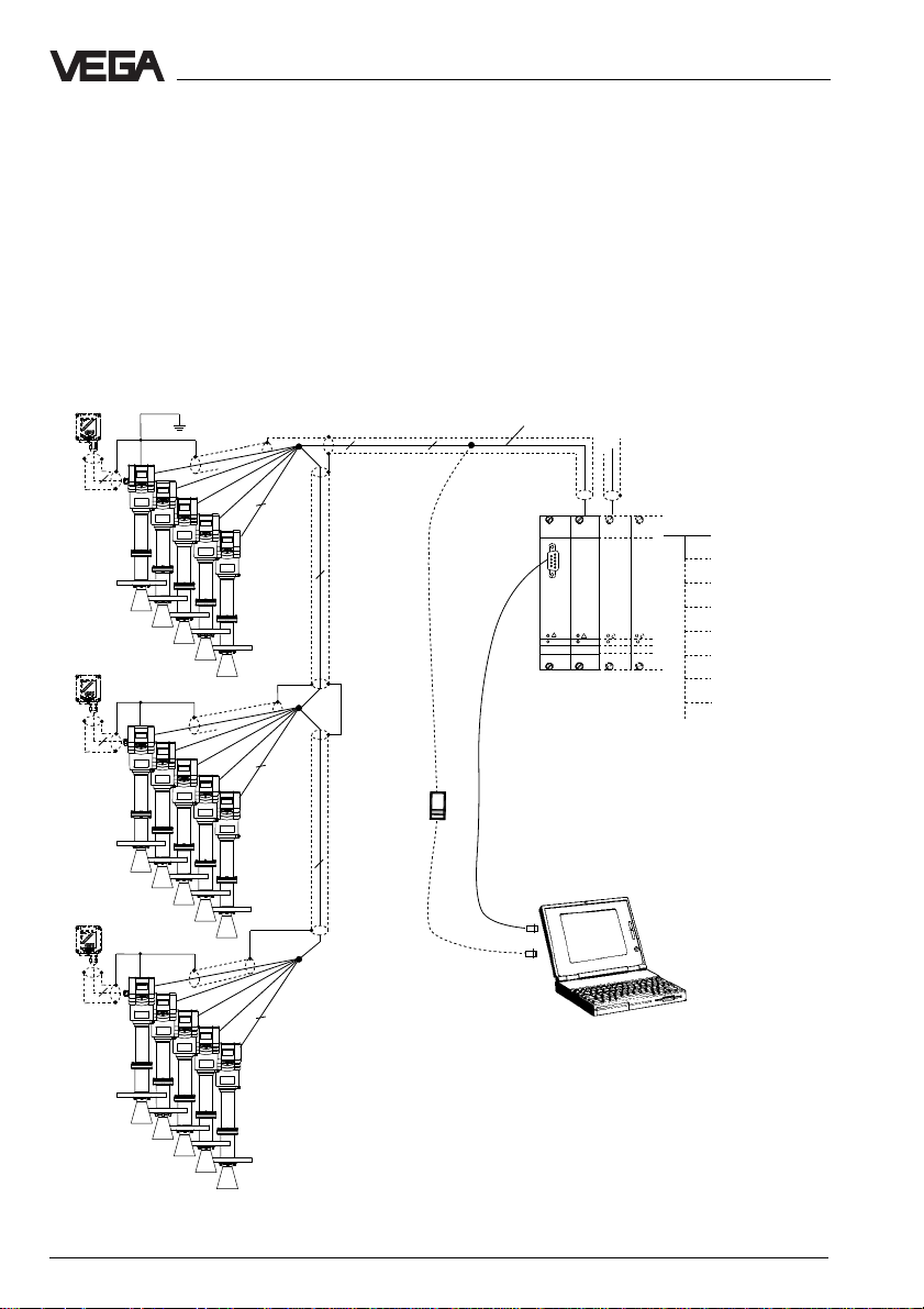
Page 17
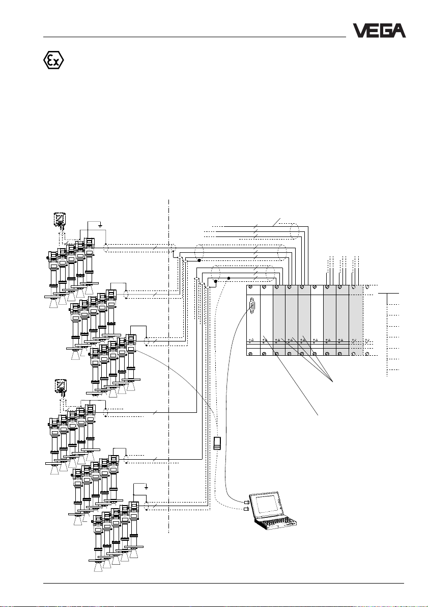
Types and versions
Measuring system with five VEGAPULS 56V Ex, 56V Ex0 per two-wire line
via separator VEGATRENN 548V Ex on the processing system
VEGALOG 571
• Two-wire technology, voltage supply and digital output signals via one two-wire line from the
separator
• Five sensors on one two-wire line
• Measured value indication integrated in the sensor
• Optionally external indicating instrument with analogue and digital indication (can be
mounted up to 25 m separated from the sensor)
• Adjustment with or without adjustment module MINICOM (can be plugged into the sensor or
into the external indicating instrument VEGADIS 50)
• Max. resistance of the signal line 15␣ Ω per wire or 1000␣ m cable length (see also approval
certificates of the separators)
VEGADIS 50
2
VEGADIS 50
2
Ex-area Non-Ex-area
EEx ia
2
EEx ia
2
2
2
EEx ia
2
EEx ia
2
Screened line in case of electromagnetic interferences
2
2
2
2
2
2
2
2
2
CPU
VEGALOG
VEGATRENN
VEGATRENN
VEGALOG
571 CPU
571 EV
VEGATRENN
548
548
1)
see previous
page
VEGALOG
VEGATRENN
VEGATRENN
571 EV
548
548
548
Separator VEGATRENN
548V␣ Ex (max. 15 sensors per
card)
Input card of VEGALOG 571
(max. 15 sensors can be
connected per input card via the
separator card)
VEGAPULS 56V
5 sensors per two-wire line
individual grouping
1)
see previous page
VEGAPULS 56V 17
Page 18
Types and versions
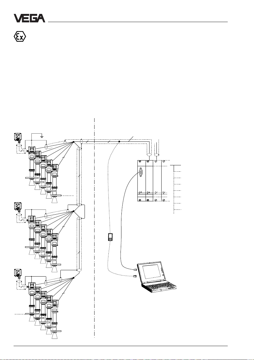
Measuring system with 15 VEGAPULS 56V Ex, 56V Ex0 with pressure tight
encapsulated connection box via one two-wire line on the processing
system VEGALOG 571
• Two-wire technology, voltage supply and digital output signals via one two-wire line from the
processing system VEGALOG 571
• Up to 15 sensors on one two-wire line, for operation in Ex zone 1 (VEGAPULS 56V␣ Ex) or
Ex zone 0 applications (VEGAPULS 56V␣ Ex0)
• Measured value indication integrated in the sensor
• Optionally external indicating instrument with analogue and digital indication (can be
mounted up to 25 m separated from the sensor)
• Adjustment with or without adjustment module MINICOM (can be plugged into the sensor or
into the external indicating instrument VEGADIS 50)
• Max. resistance of the signal line 15␣ Ω per wire or 1000␣ m cable length
VEGADIS 50
4
VEGADIS 50
4
VEGADIS 50
4
Zone 1
Zone 0
Ex-area
EEx d ia EEx e
2
2
Zone 1
Zone 0
2
2
2
VEGAPULS 56V
(15 sensors per
two-wire line
individual grouping)
Non-Ex-area
Screened line in case of electromag-
2
2
netic interferences
1)
Current outputs
Voltage outputs
CPU
Relays
Digital connectability
VEGALOG
VEGALOG
571 CPU
571 EV
Processing system VEGALOG 571 with input cards in
19“-rack. 15 sensors on one
module card and two-wire
line
1)
Sensor lines should be looped in screened cables. Earth the
Fault signals
Connection to all
BUS-systems
Transistor outputs
cable screens on the processing system or better on the sensor.
In case of stronger electromagnetic interferences it is useful to
earth the cable screens on both ends. However it must be noted
that no earth compensation currents flow via the screens. In
case of earthing on both sides earth compensation currents are
avoided by connecting the cable screen on one earth side (e.g.
in the switching cabinet) via a capacitor (e.g. 0,1␣ µF; 250␣ V) to
the earth potential.
18 VEGAPULS 56V
Page 19

Technical data
3 T echnical data
3.1 Data
Power supply
Supply voltage from signal conditioning instrument VEGAMET
Fuse 0,5 A (slow-blow)
Current consumption max. 22,5 mA
Power consumption max. 80 mW; 0,45 VA
Load resistance of the signal line max. 15␣ Ω (7,5␣ Ω
Measuring range
1)
Standard 0 … 20 m
Measurement in standpipe
- VEGAPULS 56 on DN 50 0 … 16 m
- VEGAPULS 56 on DN 100 0 … 19 m
Output signal (see also "Outputs and processing“)
Digital measuring signal (VBUS)
Adjustment
- PC and adjustment software VEGA Visual Operating
- adjustment module MINICOM
- signal conditioning instrument VEGAMET (6-key-adjustment field on signal conditioning
instrument)
Accuracy (typical values under reference conditions)
Class accuracy < 0,1 % (deviation in characteristics including
Linearity error better than 0,05 %
Influence
- of the ambient temperature
- of the process temperature
2)
2)
- of the process pressure 0,025 %/bar
Resolution of the digital output signal 0,005 % (relating to max. measuring range)
Adjustment time 1 … 10 s (dependent on factory setting)
Resolution 1 mm
or processing system VEGALOG 571
(max. 36 V DC)
with separator VEGATRENN 548V␣ Ex) per
wire or max. 1000␣ m cable length
2)
repeatability and hysteresis according to the
limit point adjustment relating to max.
measuring range)
0,06 %/10 K
negligible (0,004 %/10 K at 5 bar)
(0,003 %/10 K at 40 bar)
1)
Min. distance of the antenna tip to the medium 5 cm
2)
Reference conditions according to IEC 770
VEGAPULS 56V 19
Page 20
Technical data
Measuring characteristics
Frequency 5,8 GHz (USA 6,3 GHz)
Intervals 0,6 s
Min. span between full and
empty adjustment 10 mm (recommended 50 mm)
Beam angle (at –3 dB)
- with DN 80 38° (only for standpipe measurement)
- with DN 100 30° (only for standpipe measurement)
- with DN 150 20°
- with DN 200 16°
- with DN 250 14°
Ambient conditions
Ambient temperature on the housing -20°C … +60°C
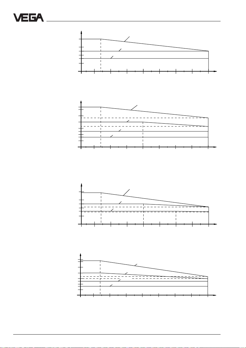
Flange temperature (process temperat.) -40°C … +350°C (pressure dependent), see
following diagrams
Vessel isolation with process temperatures of more than 200°C
the rear of the flange must be covered with a
heat isolation, see chapter "4 Mounting and
installation“.
Storage and transport temperature -40°C … +80°C
Protection IP 66/IP 67
Protection class
- two-wire sensor II
- four-wire sensor I
Overvoltage category III
Vessel pressure max. 64 bar (temperature dependent), see
following diagrams
Burst pressure
- at 20°C > 400 bar
- at 350°C > 250 bar
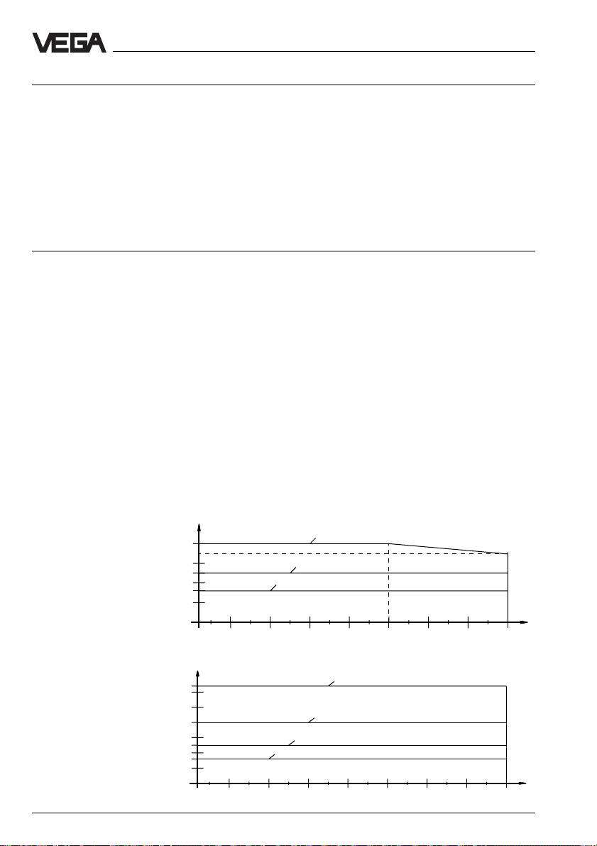
Flange DIN DN 50
Material: 1.4571
Seal surface acc. to
DIN 2526 form B, C, D, E
Flange DIN DN 50
Material: 1.4571
bar
40
25
16
-40 0 50 100 150 200 250 300 350
bar
64
PN 40
PN 25
PN 16
PN 64
Groove and tongue acc.
to DIN 2512 form F, N
20 VEGAPULS 56V
40
25
16
-40 0 50 100 150 200 250 300 350
PN 40
PN 25
PN 16
˚C
˚C
Page 21
Technical data
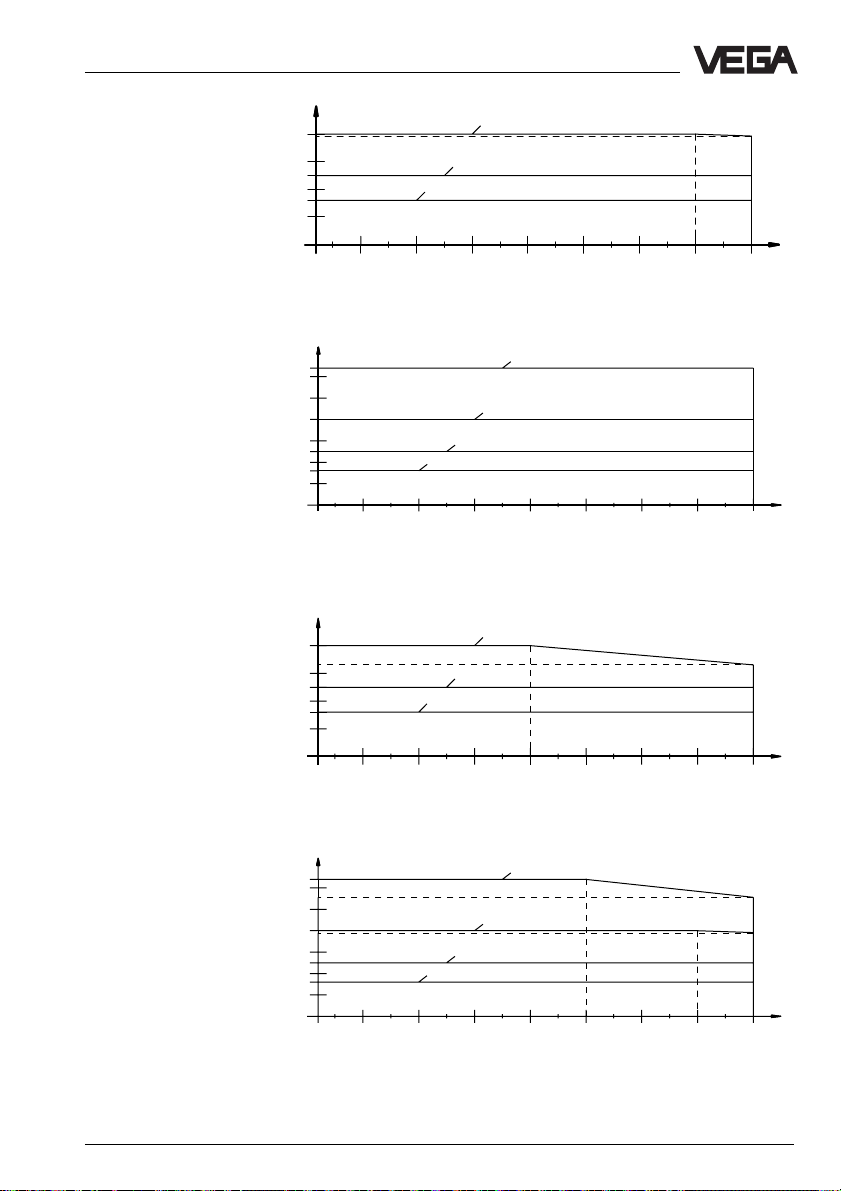
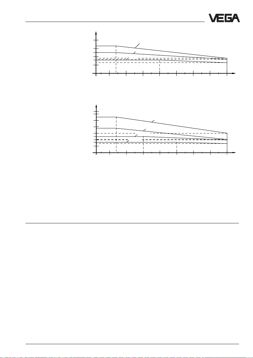
Flange DIN DN 80
Material: 1.4571
Seal surface acc. to
DIN 2526 form B, C, D, E
Flange DIN DN 80
Material: 1.4571
Groove and tongue acc.
to DIN 2512 form F, N
Flange DIN DN 100
Material: 1.4571
Seal surface acc. to
DIN 2526 form B, C, D, E
bar
40
25
16
-40 0 50 100 150 200 250 300 350
bar
64
40
25
16
-40 0 50 100 150 200 250 300 350
PN 16
bar
40
25
16
PN 40
PN 25
PN 16
PN 64
PN 40
PN 25
PN 40
PN 25
PN 16
˚C
˚C
-40 0 50 100 150 200 250 300 350
Flange DIN DN 100
Material: 1.4571
bar
64
PN 64
Groove and tongue acc.
to DIN 2512 form F, N
40
25
16
-40 0 50 100 150 200 250 300 350
VEGAPULS 56V 21
PN 40
PN 25
PN 16
˚C
˚C
Page 22
Technical data
Flange DIN DN 150
Material: 1.4571
Seal surface acc. to
DIN 2526 form B, C, D, E
Flange DIN DN 150
Material: 1.4571
Groove and tongue acc.
to DIN 2512 form F, N
Flange DIN DN 200
Material: 1.4571
Seal surface acc. to
DIN 2526 form B, C, D, E
bar
40
25
16
-40 0 50 100 150 200 250 300 350
bar
64
40
25
16
-40 0 50 100 150 200 250 300 350
bar
40
25
16
PN 40
PN 25
PN 16
PN 64
PN 40
PN 25
PN 16
PN 40
PN 25
PN 16
˚C
˚C
-40 0 50 100 150 200 250 300 350
Flange DIN DN 200
Material: 1.4571
Groove and tongue acc.
to DIN 2512 form F, N
bar
64
40
25
16
-40 0 50 100 150 200 250 300 350
PN 16
PN 64
PN 40
PN 25
22 VEGAPULS 56V
˚C
˚C
Page 23
Technical data
Flange DIN DN 250
Material: 1.4571
Seal surface acc. to
DIN 2526 form B, C, D, E
Flange DIN DN 250
Material: 1.4571
Groove and tongue acc.
to DIN 2512 form F, N
bar
40
25
16
-40 0 50 100 150 200 250 300 350
bar
64
40
25
16
-40 0 50 100 150 200 250 300 350
PN 16
PN 16
PN 40
PN 25
PN 64
PN 40
PN 25
Flanges according to ANSI (ASA) B16.5 seal surface RF, material 1.4571 in sizes 2“ to 10“
can be used over the complete temperature range of -40°C␣ …␣ 350°C with the appropriate
nominal pressures of 150␣ lbs, 300␣ lbs, 600␣ lbs and 900␣ lbs.
Further flanges and appropriate process data on request.
˚C
˚C
Connection lines
Two-wire sensors supply and signal via one two-wire line;
max. line resistance 15␣ Ω
Cross-section area of conductor generally 2,5 mm
per wire or 1000 m cable length
Earth connection max. 4 mm
2
2
Cable entry
- Ex ia-terminal box (adjustment module) 2 x M20 x 1,5 (cable diameter 5 … 9 mm)
- Ex d-connection housing 2 x 1/2“ NPT EEx d (cable diameter of the
connection cable 3,1␣ …␣ 8,7␣ mm or
0,12 … 0,34 inch)
VEGAPULS 56V 23
Page 24

Ex-technical data (note the approval documents in the yellow binder)
Classification
- d pressure tight encapsulation
- ia intrinsically safe in conjunction with a
separator or safety barrier)
Version without Exd-connection housing
VEGAPULS 56V Ex
- classification II 2G EEx ia IIC T6
- Ex-approved Zone 1 (ATEX)
Zone 1 (CENELEC; PTB, IEC)
VEGAPULS 56V Ex0
- classification II 1G EEx ia IIC T6
- Ex-approved Zone 0, Zone 1 (ATEX)
Zone 0, Zone 1 (CENELEC, PTB, IEC)
Version with Exd-connection housing
VEGAPULS 56V Ex
- classification II 2G EEx d ia IIC T6
- Ex-approved Zone 1 (ATEX)
Zone 1 (CENELEC; PTB, IEC)
VEGAPULS 56V Ex0
- classification II 1/2G EEx d ia IIC T6
- Ex-approved Zone 0, Zone 1 (ATEX)
Zone 0, Zone 1 (CENELEC, PTB, IEC
Permissible ambient temperature
on the housing
- T6 -40°C … +55°C
- T5, T4, T3, T2, T1 -40°C … +70°C
- T4, T3, T2, T1 (with Ex␣ d-housing) -40°C … +78°C
- T4, T3, T2, T1 (without Ex␣ d-housing) -40°C … +85°C
Permissible ambient temperature
on the antenna system when used
in Ex-areas
- T6 -40°C … +85°C
- T5 -40°C … +100°C
- T4 -40°C … +135°C
- T3 -40°C … +200°C
- T2 -40°C … +300°C
- T1 -40°C … +350°C
Technical data
Materials
Housing Aluminium diecasting (GD-AlSi10Mg)
Flange 1.4571 or Hastelloy C22
Antenna ceramic (Al2O3), 1.4571 or Hastelloy C22
Seal of the ceramic tip Tantalum
Exd-connection housing
(only EExd-version) Aluminium-chill casting (GK-Alsi7Mg)
24 VEGAPULS 56V
Page 25

Technical data
Weights in kg (1 psi = 0,0689 bar)
DIN 16 bar 25 bar 40 bar 64 bar
- DN 50 6,9 -- 7,7 8,5
- DN 80 8,8 -- 10,0 10,9
- DN 100 9,8 -- 11,7 14,1
- DN 150 14,6 -- 18,7 27,5
- DN 200 21,0 -- 26 48
- DN 250 29,6 38,2 38,5 61,4
ANSI 150 psi 300 psi 600 psi 900 psi
- 2“ 6,3 7,6 8,5 15,3
- 3“ 8,1 11,3 13,1 17,2
- 4“ 11,7 16,2 22,6 28,5
- 6“ 15,8 26,7 44,0 56,2
- 8“ 27,0 50,0 85,0 100,0
- 10“ 35,8 60,7 108,0 136,0
CE-conformity
VEGAPULS radar sensors meet the protective regulations of EMVG (89/336/EWG) and
NSR (73/23/EWG). The conformity has been judged according to the following standards:
EMVG Emission EN 50 081 - 1: 1992
NSR EN 61 010 - 1: 1993
Susceptibility EN 50 082 - 1: 1995
Outputs and processings
Signal output
Signal output digital output signal in two-wire technology
Two-wire technology:
The digital output signal (measuring signal) is modulated to the power supply and processed in the signal conditioning instrument or in the processing system.
Display indication
Indication - optionally integral scalable analogue and
The four-wire line to the external indicating instrument VEGADIS␣ 50 must be looped as
screened cable, see "5 Electrical connection“.
VEGAPULS 56V 25
(VBUS)
digital indication of measured values
- optionally external measured value indication,
separated up to 25 m and supplied by the
sensor. The external indication (VEGADIS 50)
can be mounted in Ex-area.
Page 26

3.2 Dimensions
Aluminium housing
Technical data
Aluminium housing with Exd-connection housing
(opened)
370
205
320
ø165
213
185
25
116
18
23
ø200
ø76
(opened)
370
205
320
20
75
185
213
ø220
25
116
20
120
ø96
ø18
ø125
DN 50
Pipe antenna
ø18
ø160
DN 80
Pipe antenna
ø18
ø180
DN 100
26 VEGAPULS 56V
Page 27

Technical data
22
ø285
205
ø146
ø22
ø240
DN 150
ø340
ø197
ø22
ø295
DN 200
24
ø405
296
ø241
ø26
ø355
DN 250
26
380
VEGAPULS 56V 27
Page 28

External indicating instrument VEGADIS 50
,
38
ø5
82
Technical data
48
10
Pg 13,5
135
118
108
85
Note:
Cable diameter of the connection cable min. 5␣ mm
Mounting on carrier rail 35␣ x␣ 7,5 according to EN␣ 50␣ 022 or flat
screwed
and max. 9␣ mm. Otherwise the seal effect of the
cable entry will not be ensured.
Flange dimensions according to ANSI
d
2
b
,
d
f
4
k
D
Size Flange Seal ledge Holes
Db k d
2" 150 psi 152,4 19,0 120,7 91,9 4 19,1
3" 150 psi 190,5 23,8 152,4 127,0 4 19,1
4" 150 psi 228,6 23,8 190,5 157,2 8 19,1
6" 150 psi 279,4 25,4 241,3 215,9 8 22,4
D = outer flange diameter
b = flange thickness
k = diameter of hole circle
d1= seal ledge diameter
f = seal ledge strength
1
/16" = approx. 1,6 mm
d2= diameter of holes
1
No. d
2
Adjustment module MINICOM
Tank 1
m (d)
12.345
67,5
28 VEGAPULS 56V
ESC
+
-
32,5
OK
Adjustment module for insertion into
VEGAPULS 56 sensors or into the external
indicating instrument VEGADIS 50
74
Page 29

Technical data
3.3 Approvals
When using radar sensors in Ex and StExareas or on ships the instruments must be
suitable and approved for these explosion
zones and applications. The suitability is
checked by the approval authorities and is
certified in approval documents.
VEGAPULS 56 radar sensors are approved
for Ex zone 1 and zone 0, this is ensured by
two Ex-concepts.
Sensors with classification EEx␣ ia must be
operated for use in Ex-areas via the separators VEGATRENN 548V␣ Ex. They provide
intrinsically safe (ia) circuits.
Sensors with classification EEx␣ d␣ ia can be
directly connected to the signal conditioning
instrument or the processing system for use
in Ex-areas as the connection box of the
EEx␣ d-sensors is pressure tight encapsulated and the ignition proof barrier is located
in the pressure tight encapsulated connection box. The resistance of the signal lines
must not exceed 15␣ Ω per wire.
Please note the attached approval documents (yellow binder) when you want to use
the sensor in Ex-area.
Test and approval authorities
VEGAPULS radar sensors are tested and
approved by the following monitoring, test
and approval authorities:
- PTB
(Physikalisch Technische Bundesanstalt Physical Technical Approval Authority)
- FM
(Factory Mutual Research)
- ABS
(American Bureau of Shipping)
- LRS
(Lloyds Register of Shipping)
- GL
(German Lloyd)
- CSA (applied)
(Canadian Standards Association)
VEGAPULS 56V 29
Page 30

,,
,,
,,
,,
,,
,,
,,
,,
,,
,,
,,
,,
,,
,,
,,
,,
,,
,,
4 Mounting and installation
4.1 General installation instructions
Measuring range
The reference plane for the measuring range
of the sensors is the flange face. The measuring range is 0␣ …␣ 20␣ m. For measurements in
surge or bypass pipes (pipe antenna) the
max. measuring distance is reduced (see
"Technical data - Meas. range“).
Mounting and installation
Please note that for measurements where the
measured product reaches the sensor
flange, build-up on the antenna is possible
which can cause measurement errors. Therefore the min. distance of the antenna to the
medium should be 5 cm.
Reference plane
min. meas.
distance
full
min.
min. meas.
distance
Meas. range
empty
max. meas. distance 20␣ m
Measuring range (operating range) and max. measuring distance
Note: The use of the sensors in solid applications is restricted.
False reflections
Flat obstructions and struts cause large false
reflections. They reflect the signal with high
amplitude.
Round profile interfering surfaces have a
diffuse reflection of the radar signals and
If flat obstructions in the range of the radar
signals cannot be avoided, it is recommended to reflect the interfering signals with
a deflector. Due to this scattering the interfering signals will be low in amplitude and diffuse so that they can be filtered out by the
sensor.
cause false reflections with low density.
Hence they are less critical than reflections
from flat surfaces.
Round profiles diffuse the radar signals
Profile with smooth interfering surfaces cause large
false echoes
30 VEGAPULS 56V
A deflector causes signal scattering
min. meas.
distance
full
empty
Page 31

Mounting and installation
Emission cone and false reflections
The radar signal is focused by the antenna
system. The signal leaves the antenna in
conical form similar to the beam pattern of a
spotlight. This emission cone angle depends
on the antenna used.
Any object in this emission cone causes a
reflection of the radar signal. Within the first
few metres of the emission cone mechanical
obstructions cause strong false reflections. In
a distance of 6 m the false signal of a pipe
has 9-times more amplitude than at a distance of 18 m.
Measuring
distance
0m
30••
10 m
40••
20 m
6,8 m 6,8 m
0
Emission cone of a DN!100 horn antenna
Measuring
distance
0m
100 %
emitted power
50 %
5,3 m5,3 m
10 m
20 m
5,0 m
3,5 m
20••
30••
0
100 %
emitted power
50 %
emitted power
5,0 m
3,5 m
Emission cone of a DN 150 horn antenna
VEGAPULS 56V 31
Page 32

Mounting and installation
Measuring
distance
0m
14••
100 %
22••
0
Emitted power
50 %
3,8 m
2,4 m
Emitted power
10 m
20 m
3,8 m
2,4 m
Emission cone of a DN 250 horn antenna
Heat isolation
In case of process temperatures of more
than 200°C an isolation on the rear of the
flange is necessary to separate the radiation
heat from the sensor electronics.
4.2 Measurement of liquids
Sensor on DIN-socket piece
Most of the time the mounting of radar sensors is made on short DIN-socket pieces.
The instrument flange is the reference plane
of the measuring range. The antenna should
always protrude out of the flange pipe.
Reference plane
Mounting on short DIN-socket piece
When the DIN-socket piece is longer, note
that the horn antenna must protrude at least
10 mm out of the socket.
The best would be to include the sensor
isolation into the vessel isolation and isolate it
up to approx. the first pipe segment.
40°C
60°C
240°C
350°C
100°C
Mounting on a longer DIN-socket piece
Vessel isolation
max. 350°C
When mounting on dished end vessels the
antenna has to protrude at least 10 mm.
Heat isolation
32 VEGAPULS 56V
>!10!mm
Page 33

Mounting and installation
>␣ 10␣ mm
Sensor directly on the vessel top
Dependent on the construction of the vessel
(sensor weight), flat mounting directly on the
vessel top would be a favourable solution.
The top side of the vessel is the reference
plane.
Mounting on dished end vessel
Do not mount the transmitter in the centre of
the dished end of the tank or close to the wall
of the vessel, but approx. 1/2 vessel radius
from the middle or from the outer wall of the
vessel.
Dished tank ends can act as paraboloidal
reflectors. If the radar sensor is placed in the
"focus“ of a parabolic tank end, the sensor
receives amplified false echoes. The radar
sensor must be mounted outside the "focus“
hence parabolic amplified echoes are
avoided.
Reference plane
1
/2 vessel radius
Mounting on dished vessel end
Reference plane
Mounting directly on flat vessel top
4.3 Measurement in a standpipe (surge or bypass pipe)
General instructions
Pipe antennas are an option in vessels which
are mechanically complex or where the product surface is very turbulent.
By focusing of the radar signals within the
measuring pipe, also products with small
dielectric constant figures (ε
be reliably measured.
The surge pipes which are open at the bottom must extend over the full measuring
range (i.e. down to 0% level).
Suitable will be a deflector at the tube end.
The medium is therefore reliably detected in
the range of the min. level. This is mainly
important for mediums with a dielectric constant figure of less than 5.
= 1,6 to 3) can
r
VEGAPULS 56V 33
Page 34

Mounting and installation
Surge pipe welded to
the tank
Deflector
Vent
Surge pipe in the socket
piece
Hole in the
intermediate flange
max.
min.
Pipe antenna systems in the tank
Also note the required vent in the surge pipe.
These vent or compensation holes must be in
one axis with the hole in the intermediate
flange (polarisation direction of the radar
signals).
Hole
100 %
0%
Pipe flange system as bypass pipe
As an alternative to the surge pipe in the
vessel, a pipe antenna system outside the
vessel is possible as bypass pipe.
Note that with a measurement in the surge or
bypass pipe the max. measuring range is
100 %
reduced by 5 … 20 % (e.g. DN 50: 16 m
instead of 20 m and DN 100 only 19 m instead of 20 m).
75 %
Direct the sensor such that the hole in the
intermediate flange is in one axis with the
pipe holes or pipe openings. The polarisation
of the radar signals enables considerably
more stable measurements with this directing.
Extended bypass pipe on the vessel with strong
product movements
34 VEGAPULS 56V
0%
Page 35

Mounting and installation
Adhesive products
When measuring adhesive products, the
inner diameter of the surge pipe must have a
longer nominal width, e.g. 100 mm, so that
build-up does not cause measuring errors.
Surge pipe diameters of DN 50 to DN 150
can be connected.
DN 50
ø 50
DN 80
ø 80
Standpipe measurement in inhomogeneous products
If you want to measure inhomogeneous or
laminated products in a surge pipe, it must
have holes, long holes or slots. These openings ensure that the liquid is mixed and corresponds to the other vessel liquid.
ø 100
DN 100
DN 150
ø 150
homogeneous
liquids
inhomogeneous
liquids
Openings in a surge pipe for mixing of inhomogene-
slightly inhomogeneous
liquids
strongly inhomogeneous
liquids
ous products
The more inhomogeneous the measured
product, the closer the openings should be.
Pipe antenna with DN 50, DN 80, DN 100 and DN 150
VEGAPULS 56V 35
Page 36

Mounting and installation
Polarisation direction
For reasons of radar signal polarisation the
holes and slots must be positioned in two
rows displaced by 180°. The mounting of the
radar sensors must then be such that the
hole of the sensor which is in the intermediate
flange, is in one axis with the row of holes of
the standpipe.
Hole
Standpipe with ball valve
When using a ball valve in a surge pipe, it is
possible to carry out maintenance and service work without opening the vessel (e.g.
with liquid gas or toxic products).
The ball valve diameter must correspond to
the pipe size and provide a flush surface
when in open position.
Note that the surge pipe ventilation is available.
DN 50
Ball valve
Rows of holes in one axis with the hole
Correct
Hole
The sensor must be directed with the hole to the rows
of holes or openings.
36 VEGAPULS 56V
Wrong
Lockable measuring pipe on a pipe antenna system
Surge pipe ventilation
ø50
Deflector
Page 37

Mounting and installation
A deflector provided at an angle of > 45°
avoids in case of products with small relative
dielectric constant that the vessel bottom is
detected as level instead of the medium.
Ventilation holes
Pipe antenna systems must be provided with
a ventilation hole at the upper end of the
surge pipe. A missing hole will cause wrong
measurements.
Correct
Pipe antenna: The surge pipe open to the bottom
must have a ventilation or a compensation hole.
Wrong
VEGAPULS 56V 37
Page 38

Construction instructions for standpipe
Flange DN 50
100 %
Rz ≤ 30
150…500
Welding neck flange
2,9…6
Welding of the connecting sleeve
5…15
0,0...0,4
Mounting and installation
Radar sensors for measurement on surge or
bypass pipes are used in flange sizes
DN!50, DN!80, DN!100 and DN!150.
On the left is the construction of a measuring
pipe (surge or bypass pipe) in the example
of a sensor with a DN!50 flange.
The radar sensor with a DN!50 flange is only
in conjunction with a measuring pipe a functional system.
The measuring pipe must be smooth inside
(average roughness Rz!≤!30). Use as measuring pipe a stainless steel pipe without
joint. Extend the measuring pipe to the required length with welding neck flanges or
with connecting sleeves. Note that no shoulders are caused in the pipe during welding.
Fasten the pipe and the flange before welding in alinement with the inner sides.
Do not just weld through the pipe wall.
Roughnesses or joints must be removed
carefully as otherwise strong false echoes
and build-up will be caused.
Connecting
sleeve
Welding neck
flanges
Burr the
holes
Deflector
0%
~45••
Welding of the welding
neck flange
2,9
1,5…2
0,0…0,4
ø 51,2
Vessel bottom
Fastening of
measuring pipe
Min. product level
to be measured
(0!%)
38 VEGAPULS 56V
Page 39

Mounting and installation
On the left you see the construction of a
measuring pipe on the example of a radar
sensor with a DN!100 flange.
Radar sensors with flanges of DN!80,
DN!100!and DN!150 are equipped with a
horn antenna. Instead of the welding neck
flange also a smooth welding flange can be
used on the sensor side of these sensors.
In agitated products, fasten the measuring
pipe to the vessel bottom. Provide additional
fastenings for longer measuring pipes.
Flange DN 100
100 %
Burr the
holes
Connecting
sleeve
Welding neck
flanges
Rz ≤ 30
Deflector
0%
2
150…500
ø 96
ø 100,8
~45••
Smooth welding
flange
Welding of the smooth
welding flange
5…15
0,0…0,4
3,6
Welding of the welding
neck flange
3,6
1,5…2
0,0…0,4
Fastening of
measuring
pipe
Min. product
level to be
measured
(0!%)
With the deflector on the measuring pipe end,
the radar signals are reflected from the vessel bottom. This ensures that in nearly empty
vessel and products with low dielectric constants, the medium is detected and not the
vessel bottom. In products with low dielectric
constant figures, the product is penetrated
by radiation and the vessel bottom delivers
at low level considerably clearer radar echoes than the product surface.
Due to the deflector, the useful signal remains
and hence the measured value can be
clearly detected in nearly empty vessel and
the 0!%-level is reliably detected.
Vessel bottom
VEGAPULS 56V 39
Page 40

Mounting and installation
4.4 False echoes
The installation place of the radar sensor
must be chosen such that no struts or
inflowing material cross the radar signals.
The following examples and instructions
show frequent measuring problems and how
they can be avoided.
Shoulders
Vessel forms with flat shoulders pointing to
the antenna can influence the measurement
due to their hard false echoes. Deflectors
above these flat shoulders diffuse the false
echoes and ensure a reliable measurement.
Correct Wrong
Screen
Flat shoulders
Inlets, e.g. for material mixing with flat surface
pointing to the radar sensor, should be covered by a screen. False echoes are hence
gated out.
Vessel installations
Vessel installations, such as e.g. a ladder
often cause false echoes. Note when planning a measurement loop that the radar signals reach the product without problems.
Correct Wrong
Ladder
Vessel installations
Ladder
Struts
Struts such as vessel installations can cause
strong false echoes which can overlay the
useful echo. Small screens avoid a direct
false echo reflection. The false echoes are
diffused and filtered out by the measuring
electronics as "echo noise“.
Correct Wrong
Correct Wrong
Screens
Screen
Shoulders (inlets)
40 VEGAPULS 56V
Struts
Page 41

Mounting and installation
Strong product movements
Heavy turbulences in the vessel, e.g. by
strong stirrers or strong chemical reactions
influence the measurement. A surge or bypass pipe (figure) of sufficient size allows,
provided that the product causes no buildup in the pipe, always a reliable measurement even with strong turbulences in the
vessel.
Correct Wrong
100 %
75 %
0%
Heavy turbulences
Products which can cause slight build-up
can be measured by using a measuring pipe
with 100 mm nominal width and more. In a
measuring pipe of this size, slight build-up is
not a problem.
Build-up
If the radar sensor is mounted too close to
the vessel wall, build-up on the vessel walls
causes false echoes. Position the radar sensor in a sufficient distance to the vessel wall.
Also note chapter "4.1 General installation
instructions“.
Correct Wrong
Build-up
Inflowing material
Do not mount the instruments in or above the
filling stream. Ensure that you detect the
product surface and not the inflowing material.
Correct
Inflowing liquid
VEGAPULS 56V 41
Wrong
Page 42

Mounting and installation
4.5 Installation fault
Socket piece too long
When mounting the antenna in a too long
socket piece, strong false reflections are
caused, aggravating the measurement. Note
that the horn antenna protrudes at least
10 mm out of the socket piece.
Correct Wrong
10 mm
Horn antenna: Correct and wrong socket length
Wrong directing to the product surface
A directing of the sensor which does not
point to the product surface will cause weak
measuring signals. If possible, direct the
sensor axis vertically to the product surface,
to reach optimum measuring results.
Parabolic effects on dished boiler head
or basket arch vessel
Round or parabolic tank tops act for the
radar signals like a parabolic mirror. If the
radar sensor is placed to the focus of such a
parabolic tank top, the sensor receives amplified false echoes. The optimum mounting is
generally in the range of the half vessel radius from the centre.
Correct
>10 mm
~ 1/
2
vessel
radius
Wrong
Correct Wrong
Wrong
Ladder
Direct sensor vertically to the product surface
42 VEGAPULS 56V
Ladder
Mounting on a vessel with parabolic tank top
Page 43

Mounting and installation
Standpipe (pipe antenna) without ventilation hole
Pipe antenna systems must be provided with
a breathing hole on the upper edge of the
surge pipe. A missing hole will cause wrong
measurements.
Correct Wrong
Pipe antenna: The surge pipe open to the bottom
must have a ventilation hole on top
Wrong polarisation direction on the
standpipe
When measuring in a surge pipe, especially if
there are holes or slots in the pipe for mixing,
it is important that the radar sensor is directed to the row of holes.
The two rows of holes of the surge pipe displaced by 180° must be in line with the polarisation direction of the radar signals. The
polarisation direction is in line with the hole.
The sensor is precisely directed by means of
the hole in the intermediate flange.
Hole
The polarisation direction is in line with the hole. The
sensor must be directed with the hole to the rows of
holes
Sensor too close to the vessel wall
If the radar sensor is mounted too close to
the vessel wall, strong interfering signals can
be caused. Build-up, rivets, screws or weld
joints superimpose their echoes to the useful
signal or useful echo. Hence note a sufficient
distance of the sensor to the vessel wall.
We recommend to choose the sensor distance such that there are no installations or
the vessel wall within the inner emission cone.
In products with bad reflection conditions, it
is useful that there are also no interfering
installations within the outer emission cone.
Note chapter "4.1 General installation instructions - Emission cone and false reflections“.
Foam generation
Strong, dense and creamy foam on the product can cause wrong measurements. Provide
measures to avoid foam or measure in a
bypass pipe. Check if necessary the use of
another measuring principle, e.g. capacitive
electrodes or hydrostatic pressure transmitters.
VEGAPULS 56V 43
Page 44

5 Electrical connection
5.1 Connection and connection cable
Safety information
Ensure that the instrument is in currentless
condition. Always switch off the power supply before you carry out terminal work on the
radar sensors. Protect yourself and the instrument, especially when you use sensors
which do not work with low voltage.
Skilled staff
Instruments which are not operated with a
protective low voltage must only be connected by skilled staff.
Connection
A standard two-wire cable with max. 2,5 mm
can be used for connection. Very often the
"Electromagnetic pollution“ by electronic
actuators, energy lines and transmitting
stations is so considerable that the two-wire
cable should be screened.
We recommend to use a screening. This
screening prevents against future interferences (figure 1).
It is favourable to earth the screens on both
ends. However it must be noted that no earth
compensation currents flow via the sensor
cable screens (figure 2). Earth compensation
currents can be avoided by connecting the
cable screen in case of earthing on both
sides on one earthing side (e.g. in the
switching cabinet) via a capacitor (e.g.
0,1␣ µF; 250␣ V) to earth potential. Use a very
low impedance earth connection (foundation,
plate or mains earth).
Ex-protection
If an instrument is used in hazardous areas,
the appropriate regulations, conformity certificates and type approvals for systems in
Ex-areas must be noted (e.g. DIN␣ 0165).
Electrical connection
Connection cable
Note that the connection cables must be specified for the expected operating conditions in
your systems. The cable must have an outer
diameter of 5␣ …␣ 9␣ mm (1/5 to 1/3␣ inch) or with
Ex␣ d-housing 3,1␣ …␣ 8,7␣ mm (0,12␣ …␣ 0,34␣ inch).
Otherwise the seal effect of the cable entry will
not be ensured.
Cables for intrinsically safe circuits must be
marked blue and must not be used for other
circuits.
Earth conductor terminal
On all VEGAPULS 56 sensors the earth conductor terminal is galvanically connected to
2
the metal process connection.
5.2 Connection of the sensor
After having mounted the sensor in the measuring position according to the instructions
in chapter "4 Mounting and installation“ loosen
the closing screw on top of the sensor. The
sensor cover with the optional display can
then be opened. Unscrew the compression
screw and shift the screw over the approx.
10 cm dismantled connection cable. The
compression screw of the cable entry is
protected with a safety lock-in position
against automatic loosening.
Now loop the cable through the cable entry
into the sensor. Screw the compression
screw again to the cable entry and clamp the
dismantled wires of the cable to the appropriate terminal positions.
The terminals operate without terminal screw.
Press the white opening buckets with a small
screwdriver and insert the copper core of the
connection line into the terminal opening.
Check the position of the lines in the terminal
position by slightly pulling on the connection
lines.
44 VEGAPULS 56V
Page 45

Electrical connection
Figure 1: Earthing only on the sensor side
VEGAMET
515V
Figure 2: Earthing on both sides (on the signal conditioning instrument via potential
separating capacitor)
> 0,1µF
250 V AC
VEGAMET
515V
Note:
Due to the potential difference earthing on
both sides is not allowed in Ex-applications.
VEGAPULS 56V 45
Page 46

ESC
+
-
OK
12 C 567843
VBUS
Communication+-4...20mA
Display
12 C 567843
Electrical connection
Ex ia-version
Voltage supply and
Spring terminals (max.
2,5␣ mm2 cross-section area
of conductor)
digital measuring signal
+
To the indicating instrument in the
-
sensor cover or to the external indicating instrument VEGADIS 50
12 C 567843
12 C 567843
Commu-
VBUS
nication+-4...20mA
-
+
Display
ESC
OK
M20 x 1,5
(diameter of the
connection cable
5…9␣ mm)
Spring terminals (max.
2,5␣ mm2 cross-section area
of conductor)
Sockets for connection of
VEGACONNECT 2 (communication sockets)
Exd-version (loop-powered with pressure-tight encapsulated terminal box)
EEx d-connection housing
(opening in Ex-area not permitted)
Voltage supply and
digital measuring signal
-+
Adjustment module and indicating
terminal box
(opening in Ex-area permitted)
Exd-proof seal to the Exdconnection housing
1
/2“␣ NPT EEx␣ d
diameter of the
connection cable
to the Exdconnection
housing
3,1…8,7␣ mm
(0,12…0,34␣ inch)
Supply: 20 … 36 V DC, VBUS
Shield
Cover lockings
Exd-connection housing
- +
2
1
12
1
/2“␣ NPT EEx␣ d
diameter of the
connection cable
3,1…8,7␣ mm
(0,12…0,34␣ inch)
46 VEGAPULS 56V
Page 47

Electrical connection
5.3 Connection of the external indicating instrument VEGADIS 50
Loosen the four screws of the housing cover
on VEGADIS 50. You can facilitate the connection procedure by fastening the housing
cover during connection with two or one
screw on the right of the housing (figure).
Note:
Input from
sensor
SENSOR
Voltage
supply
+
-
DISPLAY
(to the indicating module in
the sensor)
DISPLAY1234 56 78
Terminal strip in
VEGADIS 50
M20 x 1,5
(diameter of the
connection cable
5…9␣ mm)
The four-wire connection cable to VEGADIS
50 should be screened and can have a
length of max. 25␣ m. The digital signals to the
indicating instrument would be interfered in
case of longer connection cable by the cable
capacities. The cable screen must be
earthed together with the signal line screen
on the sensor.
VEGADIS 50
Adjustment
module
+
ESC
-
Tank 1
m (d)
12.345
OK
Screws
12 C 567843
12 C 567843
Commu-
VBUS
nication+-4...20mA
-
+
Display
ESC
OK
VEGAPULS 56V 47
Page 48

6 Set-up
6.1 Adjustment structure
VEGAPULS 56 radar sensors can be adjusted with
- PC (adjustment program VVO),
- detachable adjustment module MINICOM
or
- signal conditioning instrument VEGAMET.
The adjustment must only be carried out with
one adjustment medium at the same time.
Adjustment with PC
The PC with adjustment program VVO (VEGA
Visual Operating) can be connected to the:
- sensor
- signal line
- signal conditioning instrument VEGAMET
514V/515V
- processing system VEGALOG 571
With the adjustment program VVO (VEGA
Visual Operating) on the PC you can adjust
the radar sensors in a very comfortable way.
The PC communicates via the interface converter VEGACONNECT␣ 2 with the sensor and
the signal conditioning instrument or with the
standard RS␣ 232-interface cable, with the
processing system VEGALOG and all connected sensors. Therefore a digital adjustment signal is superimposed to the signal
and supply line of the sensors. The adjustment can be therefore made directly on the
sensor, on any individual position of the signal line or on the processing system VEGAMET or VEGALOG.
Adjustment with the signal conditioning
instrument VEGAMET
Like with the adjustment program VVO, sensor and signal conditioning instrument
VEGAMET can be adjusted with the 6-key
adjustment field on the signal conditioning
instrument. The adjustment is possible in the
same function volume than with the adjustment program VVO on the PC.
Set-up
Adjustment with the adjustment module
MINICOM
With the adjustment module MINICOM you
adjust directly in the sensor or in the external
indicating instrument VEGADIS 50. The adjustment module MINICOM enables with the
6-key adjustment field with text display the
parameter adjustment of the sensor in the
same function volume as with the adjustment
program VVO or the signal conditioning instrument VEGAMET, however not the configuration of the measuring system.
The adjustment of the signal conditioning
instrument is only possible with the adjustment program VVO or the 6-key adjustment
field on the signal conditioning instrument.
Independent whether you set-up a measuring system (unit of sensor and signal conditioning instrument VEGAMET or processing
system VEGALOG) with the adjustment software VVO or with the signal conditioning
instrument, the adjustment procedure is
always the same:
- first of all configure a measuring system in
the menu "Configuration“ and then
- carry out the parameter adjustment of the
sensor in the menu "Instrument data“.
Before starting with the set-up:
Do not be confused by the many pictures,
adjustment steps and menus on the following
pages. Carry out the set-up with the PC
step-by-step and soon you will no more
require the following pages.
48 VEGAPULS 56V
Page 49

Set-up
6.2 Adjustment with the PC on VEGAMET
For connection of the PC to the signal conditioning instrument the interface converter
VEGACONNECT 2 is required. The PC communicates via the interface converter with the
signal conditioning instrument and with the
connected sensor (s).
The individual adjustment steps are marked
in the following with a dot:
• Choose …
• Start …
• Click to …
Now start:
• Connect the standard plug of VEGACON-
NECT 2 (9-pole) with the interface COM 1
or COM 2 of your PC.
• Insert the two small pin plugs of VEGA-
CONNECT 2 into the CONNECT-sockets
on the front side of the signal conditioning
instrument.
• Now switch on the power supply of the
signal conditioning instrument.
After approx. 1␣ …␣ 2 minutes (self-check) the
measuring system is generally in operating
condition and displays measured values.
When the signal conditioning instruments are
exceptionally not pre-configured, start now
with the following section "
continue then with the adjustments in section
"Parameter adjustment
Configuration
“.
“ and
Configuration
Create new measurement loop
• Choose the menu "
ment loop/New
window "Create new measurement loop Application“.
Configuration/Measure-
“
and you are in the menu
• Start the adjustment software VVO on your
PC.
• Choose the parameter (
ment“
Instruction before starting the
configuration:
The signal conditioning instruments are already configured according to the sensor
type ordered with the signal conditioning
instrument.
Generally you will therefore use a pre-configured signal conditioning instrument. In the
following menu "
adjustments are necessary and you can
directly choose the menu "Parameter adjustment“ on page 51.
VEGAPULS 56V 49
Configuration
“, normally no
• Click to "
, "gauge“ or "distance“) and the sen-
sor type ("
Pulse-Radar
Continue
"Level measure-
“).
“.
Page 50

Set-up
• Choose "
• Click to "
• Choose one of the two inputs of the signal
After a few seconds the menu window "
Standard level measurement
"
No options
"
New application - select meas. loop
opens.
conditioning instrument VEGAMET (VEGAMET 514V has only one sensor input) and
click to "OK“.
“.
Continue
“ and the menu window
“ and
“
Create new measurement loop - Sensor configuration
“ opens.
• Click in the menu window "
measurement loop - Sensor configuration
to "
Sensor coordination
The menu window "
opens.
Sensor coordination
Create new
“
“.
“
• Confirm with "OK“.
• Click in the menu window "
nation
“ again to "OK“.
You are again in the menu window "
Sensor coordi-
Create
new measurement loop - Sensor configuration
“
• Click to "
• Click to "
• Then click to "
50 VEGAPULS 56V
Sensor search
Input
number of the sensor which you want to
coordinate e.g. to input 1.
“.
“ and choose the serial
• Click in the menu window "
Continue
“.
Create new
measurement loop - Measurement loop
designation
“ to "
Level
“.
Page 51

Set-up
• Enter in the field "
scription
In this menu window you can choose with
which output signals your level should be
provided, e.g. as current, voltage, relay
signal etc.
• Confirm your adjustments with "OK“.
The previous menu picture appears again.
• Click to "
ments are transmitted.
You have created a measurement loop in the
signal conditioning instrument.
“ a measurement loop name.
Quit
Measurement loop de-
“ and wait until your adjust-
Parameter adjustment
In the menu "
justment
adjustments.
Adjustment
• Choose the menu "
eter adjustment
which you want to carry out the parameter
adjustment.
Instrument data/Parameter ad-
“ you carry out all important sensor
Instrument data/Param-
“ and then the sensor for
In the heading of the opening menu window
you now see the previously entered measurement loop name and the description.
• First choose "
• Click in the menu window "
"
Min/Max-adjustment
Adjustment
“.
“.
Adjustment
“ to
When you have only configured one sensor
on the signal conditioning instrument, naturally you will only have one sensor as choice.
The menu window "
opens.
VEGAPULS 56V 51
Min/Max-adjustment
“
Page 52

Set-up
You can carry out the min./max.-adjustment
"with medium“
or
"without medium“
vessel filling, also with empty vessel). Generally you will carry out the adjustment without
medium, as you will be completely independent from the actual vessel filling during the
adjustment.
When you want to carry out the adjustment
with medium, you have to carry out the min.
adjustment with emptied (also partly emptied) vessel and the max. adjustment with
filled (also partly filled) vessel. It is easy and
quick to carry out the adjustment without
medium as shown in the example.
• Choose "
• Choose in the following window if the adjustment should be made in meters (m) or
feet (ft).
• Enter a "
level and the appropriate "
in percent.
In the example the 0 %-filling is at a level
distance of 3,400 m and the 100 %-filling at a
level distance of 0,500␣ m.
Note:
The sensor can only detect levels within the
defined operating range. For detection of
levels outside the operating range, the operating range must be corrected appropriately
in the menu "
ronment
(adjustment with vessel filling)
(independent of the
no (adjustment without medium)
Distance
“ for the upper and lower
Filling degree
Sensor optimisation/Meas. envi-
“.
• Confirm your adjustments with "OK“ and
you are again in the menu window "
ment
“.
• Click in the menu window "Adjustment“ to
"
Quit
“.
You are now again in the menu window "
strument data parameter adjustment
“
“
The sensor electronics has now two characteristics point (min. and max.) out of which a
linear proportionality between level difference
and percentage filling of the vessel is generated. The characteristics points must naturally not be at 0 % and 100 %, however the
distance should be as big as possible (e.g.
at 20 % and at 80 %). The min. distance of
the characteristics points for the min./max.
adjustment should be 50 mm product distance. When the characteristics points are
too close together, the possible measurement
failure is increased. Therefore it would be
suitable to carry out the adjustment at 0 %
and at 100 %.
Adjust-
In-
“.
In the menu "
justment/Conditioning/Linearisation
enter later if required another linear dependence between level distance and percentage
filling degree (see subchapter linearisation).
Conditioning
• Click in the menu window "
parameter adjustment
52 VEGAPULS 56V
Instrument data/Parameter ad-
“ you can
Instrument data
“ to "
Conditioning
“.
Page 53

Set-up
The menu window "
Click to "
Scaling
In the menu "
0 % and 100 %-values of the parameter and
their unit. You inform the sensor e.g. that
at␣ 0␣ %-filling there are still 45 l and at 100␣ %filling 1200 l in the vessel. The sensor display
shows with empty vessel 45 l (0␣ %) and with
full vessel 1200 l (100␣ %).
Conditioning
“.
Scaling
“ you enter the actual
“ opens.
As parameter you can choose
less
(figures),
distance“
can then be coordinated to the parameter.
The sensor display shows then the figure in
the selected parameter and unit.
• Save the adjustments in the menu "
with "OK“.
A warning is displayed that the indication was
previous adjusted to percent. Confirm the
adjustment to get the indication in liters. The
adjustments are now transferred to the sensor and you are again in the menu window
"
Conditioning
• Click in the menu window "
"
Quit
• Click in the menu window "
volume, mass, height a
and an appropriate unit (e.g. l. hl)
“.
“.
parameter adjustment
"dimension-
Conditioning
Instrument data
“ to "
Quit
nd
Scaling
“ to
“.
“
Linearisation
The relation of level and volume is described
in so called linearisation curves. When there
is another linear dependence in your vessel
between level (percentage value of the level)
and the volume (linearised value of the volume), choose the menu "
Parameter adjustment/Conditioning
VEGAPULS 56V 53
Instrument data/
“.
Page 54

Set-up
• Click in the menu window "
the menu point "
Linearisation
In the menu window "
that "
Linear
“ is pre-adjusted. This means that
Conditioning
“.
Linearisation
“ to
“ you see
the dependence between the percentage
value of the filling volume and the value of the
level is linear. Beside the two pre-adjusted
linearisation curves "
"
Spherical tank
programmable curves
Cylindrical tank
“ and
“ you can also enter six "
“.
user
• To enter an own vessel geometry of a user
programmable filling curve, click to "
programmable curve
• Then click to "
Edit
“.
“.
user
First of all a linear relation (a straight line) is
displayed. In the field "
value
“ the present level in percent of the ad-
Transfer measured
justed measuring range (measuring window) is
displayed. You have adjusted the measuring
range with the min./max. adjustment to 0,500
up to 3,400 m.
Max.
Min.
100 % (0,500 m) corresp. to
1200 liters
Meas. range
0 % (3,400 m) corresp. to
45␣ liters
The user programmable linearisation curve is
generated with index markers, the so called
value pairs. A value pair consists of "
earised
“ (percentage value of the filling) and
"
Percentage value
“ (percentage value of the
Lin-
level relating to the measuring range). When
the index markers or value pairs of your
vessel are not known to you, you have to
gauge the vessel by liters.
Gauging by liters
In the characteristics of the following figure
you see five index markers (0, 1, 2, 3, and 4)
or value pairs. There is always a linear interpolation between the index markers.
54 VEGAPULS 56V
Page 55

Set-up
• Click to "
Index marker 0 is at 0 %-filling (percentage
value [%]), corresponding to an actual distance to the product surface of 3,400 m, in
the example the empty vessel. The volume
value is therefore 45 liters (rest filling of the
vessel).
Index marker 1 is at a level of 20 % (20 % of
the measuring distance of 0,500␣ m␣ …␣ 3,400␣ m).
According to our example there are 100 liters
at 20 % filling in the vessel.
Index marker 2 is at a level of 40 %. At this
filling level there are 250 liters in the vessel.
Index marker 3 is at a level of 80 %, where
1000 liters are in the vessel.
Index marker 4 is at a level of 100 % (product distance 0,500 m), where 1200 liters are
in the vessel.
Show scaled values
adjusted unit displayed on the y-axis (left
bottom corner in the menu window).
“, to have the
Again in the menu window "
can enter with the menu point "
time
“ a measured value integration. This is
useful for fluctuating product surfaces to
avoid a permanently varying measured value
indication and output.
As a standard feature an integration time of 0
seconds is adjusted.
• Quit the menu window "
with "OK“ and you are again in the menu
window "
• Quit the menu window with "
You are again in the menu window "
Conditioning
ment data parameter adjustment
• Click to "
Outputs
• Choose in the main menu window "
Quit
“.
ment data/Parameter adjustment
the following window the requested sensor.
• Choose in the menu window "
data parameter adjustment
Conditioning
Integration
Integration time
“.
Quit
“.
“.
Instrument
“ "
Outputs
“ you
“
Instru-
Instru-
“ and in
“.
Max. 32 index markers (values pairs) can be
entered per linearisation curve.
• Quit the menu with "OK“.
• Confirm the message with "OK“ and your
individual linearisation curve is saved in the
sensor.
VEGAPULS 56V 55
Page 56

Set-up
You are in the menu window "
• Click to "
• If you have carried out adjustments in this
• Click to "
You are again in the menu window "
• Click in the menu window "
Current output
signal reaction of the 0/4␣ …␣ 20 mA-output
signal.
menu window, click to "
Quit
“.
menu point "
choose "
Display of measured value
Sensor-Display
Outputs
“, to adjust the
Save
“.
Outputs
“.
“.
Outputs
“ to the
“ and
• Choose under "
e.g. liter.
• Enter the measuring distance in meter,
which you have entered in the min./max.
adjustment and the appropriate liters which
correspond to the min. and the max. value.
In this example this would be 45 liters and
1200 liters.
• Click to
• Click in the "
• Click in the window "
You are again in the menu window "
“.
• Click to
You are again in the menu window "
value
"
“ to "
"
Scaling for sensor display
Save
“.
Sensor-Display
Display of measured
Quit
“.
Quit
“.
ment data parameter adjustment
“ to
"
Quit
“.
“.
Outputs
Instru-
“
“
Sensor optimisation
In the menu "
carry out special optimising adjustments of
the sensors and for example optimize the
installation position of the sensor by means of
the echo curve.
Meas. environment
• Choose in the main menu window the menu
"
Instrument data/Parameter adjustment
• Choose in the menu window "
data parameter adjustment
"
Sensor optimisation
"
Sensor A
• Choose under "
"
Parameter
56 VEGAPULS 56V
“ "
Scaled
Sensor-no
“.
“ "A“ and under
Sensor optimisation
“ and then click to
“.
“ you can
“.
Instrument
“ the menu point
Page 57

Set-up
If a smaller measuring range is selected as
previously adjusted in the "
ment
“, the sensor is caused to provide e.g.
the measured values only from 20␣ …␣ 60␣ %
instead of 0␣ …␣ 100␣ % (reduction of the measuring window).
In the example the
- min-adjustment was set to 0,500 m and the
- max-adjustment to 3,400 m.
• Save the adjustments with "OK“
• Click in the menu window "
ment
“ to "
• In the menu window "
you click to the options corresponding to
your application.
Measuring conditions
Min/Max-adjust-
Meas. environ-
“.
Measuring conditions
“
• First click to "
The window "
With the menu point "
can define the measuring range of the sensor
deviating from the "
a standard feature the measuring range
corresponds to the values adjusted with the
min/max-adjustment.
VEGAPULS 56V 57
Meas. environment
Meas. environment
“ opens.
Measuring range
Min/Max-adjustment
“.
• Confirm with "OK“.
After a few seconds of saving (the adjust-
“ you
“. As
ments are permanently saved in the sensor)
you are again in the window "
ment
“.
Meas. environ-
Page 58

Set-up
In the menu point "
ally have only made adjustments when you
measure in a surge or bypass pipe (standpipe). With a standpipe measurement a shifting of the running time is caused which is
dependent on the inner diameter of the
standpipe. To consider this shifting of the
running time, it is necessary to inform the
sensor about the tube diameter (inner) of the
standpipe.
Pulse velocity
“ you gener-
Echo curve
With the menu point "
display the course and the strength of the
detected radar echo.
If you have to expect strong false echoes
due to vessel installations, a correction of the
installation position (if possible) can help by
monitoring the echo curve, to localize and
reduce the size of the false echoes.
In the following figure you see the echo curve
before the correction of the installation angle
(directing to the product surface) with a false
echo with nearly the same size than the product echo which is caused by a strut.
Echo curve
“ you can
In the menu point "
tionally possible to enter a correction factor
for the pulse velocity of the radar signal.
Note:
The radar signal spreads with light velocity.
• Quit this menu with "
not want to make any adjustment.
• Save with "OK“ the adjustments carried
out.
• Click in the menu window "
ment
“ to "
You are again in the menu window "
optimisation
58 VEGAPULS 56V
Quit
“.
Pulse velocity
Cancel
“.
“ it is addi-
“ when you do
Meas. environ-
Sensor
In the next figure you see the echo curve
after optimum directing of the sensor to the
product surface (sensor axis reaches the
product surface vertically).
Page 59

Set-up
You see that due to the strut, the false echo is
approx. 20 dB lower than the useful echo and
can therefore no more influence the measurement.
• Enter here the checked product distance
and click to "
Create new“
.
• Quit the menu window
"
Quit
“.
With the menu point "
the menu window "
cause the sensor electronics to mark false
echoes and to save in a database. The false
echoes are then treated different than the
useful echo.
• Click in the menu window "
tion
“ to the menu point "
age
“.
• Click in the menu window "
age
“ to "
Learn false echoes
window "
Learn false echoes
"Echo curve
False echo storage
Sensor optimisation
Sensor optimisa-
False echo stor-
False echo stor-
“. The small
“ opens.
“ with
“ in
“ you
Hence you cause the sensor to mark all echoes in front of the level echo as false echoes.
This avoids that the sensor detects erroneously a false echo as level echo.
• Click to "
The echo curve and the false echo marking
are shown.
Show echo curve
“.
VEGAPULS 56V 59
Page 60

Set-up
• Quit the menu with "
You are again in the menu window "
optimisation
options of the menu "
reset to basic adjustment.
• Quit the menu window "
tion
window "
choice
You are then again in the menu window "
“. With the menu point "
“ with "
Quit
Sensor optimisation sensor
“.
strument data parameter adjustment
• Click in the window "Instrument data parameter adjustment“ to "
Quit
“.
Sensor optimisation
Sensor optimisa-
“ and with "
Quit
Meas. loop data
Sensor
Reset
“ the menu
In-
“.
“ all
“ are
“.
• Close the information windows.
• Quit the menu "
• Click in the menu window "
parameter adjustment
You are again in the main menu window.
Measurement loop data
Instrument data
“ to "
Quit
“.
“.
Change COM-interface
Show measured value
Simulation
Back-up
see "Operating instruction VEGA Visual Operating (VVO)“
• Click to "
60 VEGAPULS 56V
Application
"
VEGAMET
your measuring system in the information
windows.
“, "
“, to get detailed information to
Input no. A
“ and
Page 61

Set-up
6.3 Adjustment with MINICOM or
VEGAMET
Beside the PC VEGAPULS 56V radar sensors can be also adjusted
- with the detachable small adjustment mod-
ule MINICOM
- or with the signal conditioning instrument
VEGAMET.
For the adjustment with the signal conditioning instrument VEGAMET all adjustment options are available like with the PC. The
adjustment differs just in the appearance
however not in the functionality.
With the adjustment module MINICOM all
sensor relevant adjustments are possible
(adjustment, operating range, measuring
conditions, sensor indication scaling, linearisation or false echo storage).
Not possible however are the adjustment
steps relating to the configuration of the signal conditioning instrument VEGAMET or the
processing system VEGALOG and their
signal processing (configuration of the inputs
and outputs, linearisation curves, simulation…).
VEGAMET and MINICOM are adjusted with 6
keys. A small display gives beside the measured value a short feedback on the menu
point or the figure of a menu adjustment.
Although the information quantity of the small
display cannot be compared with the adjustment program VVO, there will be no problems with the adjustment according to the
following menu plans of VEGAMET 515V and
MINICOM. Perhaps you will carry out your
adjustments more quickly and direct with the
6-key adjustment field than with the PC.
Note:
The menu plan to VEGAMET 514V is stated in
the operating instruction to VEGAMET 514V.
Indicating and adjustment surfaces of:
Signal conditioning
instrument VEGAMET
Branch, i.e. jump to the
lower menu with [OK]
%
100
+
ESC
-
OK
CONNECT
2
1
on
515 V
Interrupt adjustment
or move to the next
higher menu
Analogue
LED-indication
(0!…!100!%)
VEGAPULS 56V 61
Display,
indication of
- measured value
- menu point
- parameter
- value
Dependent on the menu point,
change the value or choose out of
the list
Choose menu window or shift
flashing cursor
Save the adjusted value or move
to the lower menu
Adjustment module MINICOM
Tank 1
m (d)
12.345
ESC
OK
Page 62

Set-up
Adjustment structure of signal conditioning instrument and adjustment module
MINICOM
Display of
measured
value
TAG1
OK
36.9
TAG2%TAG3
%
TAG1-2
%
Selection of the menu window in the
horizontal menu stage as well as
selection of fixed parameters
Main
menu
Param.
TAG1
OK
ESC
Adjustment
ESC
OK
ESC
OK
Param.
TAG2
Signal
conditioning
Scaling
Param.
TAG3
Output
Lin.
curve
The most important adjustment steps
On page 66␣ …␣ 73 you see the complete
menu plan of the signal conditioning instrument VEGAMET 515V as well as the adjustment module MINICOM. The menu plan of the
signal conditioning instrument VEGAMET
514V is nearly identical (see operating instruction to the signal conditioning instrument
514V).
Set-up the sensor in the following numerical
sequence. The appropriate numbers are
stated in the menu plans on page 66␣ …␣ 73.
Note:
The items in brackets are only accessible
with the signal conditioning instrument VEGAMET. The items with a bracket can be adjusted in addition with the adjustment module
MINICOM.
Configuration
Simulation
Integration
time␣
10
Inputs
Menu window
Parameter
Value
Meas.
loop
Outputs
1a Configuration measurement loop
1b Configuration input (generally already
pre-configured)
2) Measurement in standpipe
3 Min-/Max-adjustment
4) Measuring conditions
5) Operating range
6 Signal conditioning/Scaling
7 Outputs
8) False echo storage (only required in case
of measuring errors during operation).
9) Indication of the useful and noise level
10) Adjustment/Signal conditioning/Outputs of
the sensor display
Add’l
functions
Password
off
62 VEGAPULS 56V
Page 63

Set-up
1a Configuration measurement loop
(menu plan page 68)
1b Configuration input
First of all you have to inform the signal conditioning instrument (only VEGAMET 515V) to
which input (input 1 or input 2) the sensor is
connected. Proceed according to chapter
"6.1 Configuration measurement loop“ in the
operating instruction VEGAMET 515V (menu
plan page 68).
2) Measurement in standpipe
Adjustments are only required when the
sensor is mounted to a standpipe. With the
measurement in a standpipe the running time
of the radar signal changes which is dependent on the inner resistance of the standpipe.
Enter the distance from the sensor flange to
the medium. Then the sensor calculates a
precise running time correction and provides
exact level values (menu plan page 72).
3 Adjustment
Under the menu point "
form the sensor in which measuring range it
should operate. You can carry out the adjustment with or without medium. Generally you
will carry out the adjustment without medium
as you can adjust without filling cycle.
Adjustment
“ you in-
Adjustment without medium
Input (key) Display indication
Sensor
m(d)
4.700
Pa-
OK
OK
OK
OK
+
The distance indication flashes
slowly
rameter
adjustment
Adjustment
without
medium
Adjustment
in
(Min-adjustment)
m(d)
0.0 %
at
m (d)
XX.XXX
Now you can adjust with the "+“ and "–“-key
the distance of your sensor to the medium at
0 %-filling (example: 3,400 m).
The indication stops flashing
OK
and the adjustment will be
saved.
Hence you have adjusted to min. value.
100.0%
at
m (d)
Max.
100 % (0,500 m) corresp. to
1200 liters
XX.XXX
(Max-adjustment)
Proceed with the 100!%-value, where you
Meas. range
Min.
VEGAPULS 56V 63
0 % (3,400 m) corresp. to
45!liters
enter e.g. 0,500!m.
Page 64

Set-up
Adjustment with medium
with
medium
XXX.X
Maxadjust
at %
XXX.X
Minadjust
at %
Fill the vessel e.g. to 10 % and enter in the
menu "
Min-adjustment
“ with the "+“ and "–“keys 10 %. Then fill the vessel e.g. to 80 % or
100 % and enter in the menu "
ment
“ with the "+“ and "–“-keys 80 % or
Max-adjust-
100 %. When you do not know the distance,
you have to sound.
Note:
The sensor can only provide levels within the
defined operating range. For detection of
levels outside the operating range, this range
must be corrected appropriately in the menu
"
Sensor optimisation/Meas. environment
“
(under figure 2).
4) Measuring conditions
Enter here if you want to measure liquids or
solids and confirm the concerned meas.
conditions (menu plan page 72).
5) Operating range
Without special adjustment, the operating
range corresponds to the measuring range
in the menu "
range was already adjusted with the min./
max. adjustment. If a smaller operating range
is selected than previously adjusted in "
justment
the measured values only in a limited range,
e.g. instead of 0!…!100!% in the range of
20!…!60!% (meas. window).
Adjustment
“. The measuring
“, the sensor is caused to provide
Ad-
Example:
Min/Max-adjustment: 0,500 … 3,400 m; operating range to approx. 1,800 … 2,900 m.
Then the sensor indicates only measured
values from 20!…!60!%.
6 Conditioning / Scaling
Under the menu point "
you enter a figure corresponding to a 0 %
and 100 %-filling and choose beside the
position of the decimal point a physical unit,
e.g. distance (menu plan, page 66).
Enter in the menu window "
the figure of the 0 %-filling (in the example of
the adjustment with PC this had been 45
liters).
Signal
condit
ioning
Scaling
0 %
100 %
corre-
corre-
sponds
sponds
XXXX
XXXX
• Confirm with "OK“.
With the "–>“-key you move to the 100!%
menu. Enter the figure of your parameter
corresponding to a 100 %-filling. In the example this had been 1200 for 1200 liters.
• Confirm with "OK“.
Choose, if required, a decimal point. However note that only max. 4 digits can be
shown.
In the menu "
Prop. to
eter (mass, volume, distance…) and in the
menu "
Unit
“ the physical unit (kg, l, ft3, gal, m
…).
Conditioning/Scaling
0 % corresponds
prop.
Decimal
point
888.8
to
Mass
Unit
Kg
“ you choose the param-
“
“
3
64 VEGAPULS 56V
Page 65

Set-up
Linearisation:
Adjustment
Signal
condit
ioning
Scaling
Lin.
curve
Linear
Integr
ation
time
0 s
Pre-adjusted is a linear dependence between percentage value of the product distance and the percentage value of the filling
volume.
With the menu "Lin.curve“ you can choose
between linear, spherical tank and cylindrical
tank and user programmable. The adjustment of a user programmable linearisation
curve is only possible with the PC and the
adjustment program VVO.
7 Outputs
Under the menu "
e.g. the current output should be inverted or
which parameter should be provided by the
sensor indication (menu plan page 66).
Outputs
“ you determine if
8) False echo storage
A false echo storage is only useful when false
echo sources such as e.g. struts must be
reduced if not possible in another way (correction of the installation position). With the
creation of a false echo storage you cause
the sensor electronics to learn the false echoes and to save them in an internal database.
The sensor electronics treats these (false)
echoes different than the useful echo and
gates them out (menu plan page 72).
9) Useful and noise level
Ampl.:
XXdB
S-N:
XX
dB
In the menu
you receive important information on the
signal quality of the product echo. The higher
the amount out of "
S-N
“-value, the more reli-
able the measurement (menu plan page 72).
Ampl.: Means amplitude of the product echo
in dB (useful level)
S-N: Means Signal-Noise, i.e. the useful
level minus the level of the background noise
The larger the S-N-value (distance of the
amplitude useful level to noise level), the
better your measurement:
> 50 dB Measurement very good
40 … 50 dB Measurement good
20 … 40 dB Measurement satisfactory
10 … 20 dB Measurement sufficient
5 … 10 dB Measurement bad
< 5 dB Measurement very bad
Example:
Ampl. = 68 dB
S-N = 53 dB
This means that the noise level is only
68 dB – 53 dB = 15 dB.
53!dB signal distance mean a good reliability.
10) Adjustment/Conditioning/Outputs of
the sensor display
The menu points "
and "
Outputs
only to the sensor display. All adjustments
carried out here, only relate to the sensor
display or to the external indication. The
measured value processing is not concerned
(menu plan page 72).
Adjustment
“, "
Conditioning
“ in the MINICOM-menu relate
“
VEGAPULS 56V 65
Page 66

Set-up
TAG1-3
xx,x
xx,x
xx,x
TAG No. 1
%
Param.
TAGNo. 1
xx,x
TAG No. 2
%
xx,x
Param.
TAGNo. 2
A
Adjust
3
ment
Signal
condit
ioning
like
TAG-No.1
TAG No. 3
%
xx,x
Param.
TAGNo. 3
Outputs
mA
outputs
mA
output
no. 1
prop.
to
Percent
7
Unit
0,0%
Volt
outputs
Volt
output
no. 1
prop.
to
Percent
mA
output
no. 2
VEGAMET 515V - Menu plan
Configuration
B
see page 68 - 69
Unit
0,0%
like mAoutput no. 1
mA
range
0%
+100%
Volt
output
no. 2
Volt
range
0%
+100%
mA
output
no. 3
mA
output
4/20mA
like Volt
output no. 1
Voltage
output
0/10V
mA
at
0%
4,000
Volt
output
no. 3
mA
at
100%
20,000
Volts
at
0%
0,000
Add’l
functions
C
see page 70 - 71
Volts
at
100%
10,000
mA
Failure
limita
mode
tion
0mA
on
Failure
mode
0V
Volt
limita
tion
on
with
medium
Min
adjust
at %
0,0
LIN-
Scaling
6
Max
adjust
at %
100,0
0%
corresponds
100%
corresponds
1000
0
w.out
medium
Adjust
ment
bar
Decimal
point
888,8
3
Offset
correc
tion
Sensor
unpres
sur’d ?
OK ?
Offset
corr.
Now !
OK ?
prop.
to
undefined
0%
at
bar
0,000
Unit
– –
100%
at
bar
1,000
curve
linear
Integr
ation
time s
Density in
Kg/dm3
1,000
0
Meas.
value
limita
tion
negative
values
yes
Fail.
mode
Stan
dard
66 VEGAPULS 56V
Page 67

Set-up
Relay
outputs
METdisplay
prop.
to
Percent
Unit
0,0%
PC/
DCS
outputs
DISoutputs
DISoutp. 1
prop.
to
Percent
1) Approx. 15 minutes after the last simulation adjustment
VEGAMET returns automatically to the standard operating
mode.
1)
DISoutp.2
like DISoutp.1
Special
funct.
Reset
level
Reset
OK ?
Reset
Now!
OK ?
Real
value
corr.%
0
DISoutp. 7
like DISoutp.7
Density
corr. %
0
Unit
0,0%
Simulation
Simulation
Now!
OK?
Simulation
%
XX,X
Manual
correc
tion
Offset
correc
tion
Offset
correc
tion
OK?
Correc
tion
Now !
OK ?
Real
value
corr.
Real
value
corr.
OK?
Correc
tion
at%
0,0
Correc
tion
Now !
OK ?
Relay
output
no. 1
prop.
to
Percent
Unit
0,0%
Relay
output
no. 2
like relay
output
no. 1
Mode
Overfill
protec
Monit.
on
Low&
High
DCS
outp.1
prop.
to
Percent
Low
%
0,0
Unit
0,0%
High
%
100,0
DCS
outp. 2
like DCS outp.1
Deviat
ion
%
1,0
Deviat
ion
period
Scan
time
s
1
DCS
outp.7
like DCS outp.7
No. of
scans
10
Failure
mode
off
Add’l
functions
Switch
ing
delay
t on
t off
s
1
VEGAPULS 56V 67
s
1
Page 68

Set-up
TAG1-3
xx,x
xx,x
xx,x
1b
TAG No. 1
%
A
Config
inputs
xx,x
Param.
TAGNo. 1
TAG No. 2
%
xx,x
Param.
TAGNo. 2
see page 66 - 67
Config
meas.
loop
Single
measurement
TAG 1
level
TAG No. 3
%
xx,x
Param.
TAGNo. 3
1a
Linked
application
Application
level
1)
1)
The parameters in these menu points
can be only modified when "Reset to
linked application“ had been carried out
first.
TAG 2
level
like TAG 1
Sensor
type
Hydrostatic
1)
Mode
pressurized
vessel
1) 1)
VEGAMET 515V - Menu plan
B
Configuration
Option
no
option
Sensor
coordi
nation
Location A
Input
no. 1
Add’l
functions
C
see page 70 - 71
TAG 1
level
TAGID
TAG No. 1
Location B
Input
no. 2
Fault
signal
?
on
Location C
Input
no. 3
TAG 2
Top
press
like TAG 1
Tare
Input
from
undefined
Location D
undefined
TAG 3
Total
press
Monitoring
Input
from
undefined
Location E
undefined
Appli-
Sensor
cation
type
Hydro-
level
static
2)
2) 2) 2)
The parameters in these menu points
can be only modified when "Reset to
single measurement“ had been
carried out first.
Input
no. 1
2)
Mode
Standard
Option
no
option
Sensor
coordi
nation
Location A
Input
no. 1
Location D
undefined
Location E
undefined
TAGID
TAG No. 1
Fault
signal
?
on
Tare
Input
from
undefined
Monitoring
Input
from
undefined
2) 5) 8) 9) 10)
Serial
no.
xxxx
xxxx
Edit
ser.no
0000
0000
Input
no.
undefined
Sensor
charac
terist
ics
Min.
meas.
range
0,00
Max.
meas.
range
1,00
Sensor
optimize
I
continue in the
MINICOM-menu
on page 72
Input
1b
from
local
Met
68 VEGAPULS 56V
Page 69

Set-up
act.
dist.
m
X,XX
heavy
dust
No
Config
outputs
Config
curr.
output.
Bolt print menu points show the
sensor or measured value information and cannot be modified in
these positions.
Light grey menu points are only
displayed if required (dependent
on the adjustments in other menu
points).
Config
Volt.
output
Config
relay
output
Operat
ing
relay
Rel. 1
to
TAG No. 1
Fail
safe
relay
Relay
Standard
Rel. 1
Standard
Input
no.
undefined
fast
changes
Yes
Config
PC/
DCS
output
Rel. 2
to
TAG No. 2
In white letters you see the
parameters which can be modified with the "+“ or "-“-key and
which can be saved with the "OK“key.
With these keys you move in
the menu field to the left, right,
top and bottom.
PC/
DCS
relay
status
off
Input
no.
undefined
PC/
DCS
input
status
off
DCS 7
to
----
PC/
DCS
meas.
values
DCS 1
to
TAG No. 1
Rel. 2
Standard
Config
VEGADIS
DIS 1
to
TAG No. 1
ESC
OK
DIS 7
to
----
V no3
V no2
mA no1
to
TAG No. 1
Input
no. 2
like input
no. 1
mA no2
to
TAG No. 2
V no1
to
TAG No. 1
mA no3
to
TAG No. 3
to
TAG No. 2
to
TAG No. 3
Input
no. 4
Input
from
local
Met
Channel
no.
Input
no. 5
like input
no. 4
Input
undefined
K1
Autom.
sensor
search
Sensor
search
OK ?
Sensor
search
Now !
OK ?
VEGAPULS 56V 69
Page 70

Set-up
TAG1-3
xx,x
xx,x
TAG No. 1
%
xx,x
xx,x
Param.
Param.
TAG-
TAG-
No. 1
No. 2
AC
see page 66 - 67
Password
TAG No. 2
%
xx,x
off
TAG No. 3
%
xx,x
Param.
TAGNo. 3
Edit
lin.
curves
Info
Input
info
VEGAMET 515V - Menu plan
Configuration
B
see page 68 - 69
VEGAMET
Info
Type
MET515
V
Program
info
Program
info
xxxxxx
Serial
number
xxxx
xxxx
Instr.
addr.
1
Meas.
loop
info
TAG 1
TAG No. 1
Min
set at %
0,0
Softw.
vers.
01.13
97
Add’l
functions
Min
set at
bar
0,000
Softw.
date
47/97
TAG 2
TAG No. 2
Language
English
like TAG 1
Max
set at %
100,0
Param.
vers.
5
TAG 3
TAG No. 3
Max
set at
bar
1,000
Parameter
level
Curve
no.1
Add
lin.
point
x %
0,0
y V%
0,0
Input
no.1
continue in the
MINICOM-menu
on page 73
Edit
curve
no.1
x 0 %
0,0
y 0 V%
0,0
Input
no.2
II
like
input no. 1
Curve
Curve
no.2
no.3
like LIN-curve 1
x 1 %
x 2 %
100,0
y 1 V%
100,0
y 2 V%
100,0
100,0
Index marker number (0...32)
Input
no.4
Sensor
type
Radar
x32 %
100,0
y32 V%
100,0
Input
from
local
MET
Channel
no.
K1
Input
no.5
like input no. 4
Input
undefined
Delete
lin.point
x 0,0
y 0,0
delete
Delete
Now?
Actual
switch
status
70 VEGAPULS 56V
Page 71

Set-up
act.
dist.
m
X,XX
heavy
dust
No
Reset
VEGAMET
Reset
configuration
Reset
TAG 1
to default
Reset
OK?
Reset
Now!
OK?
Bolt print menu points show the
sensor or measured value information and cannot be modified in
these positions.
Light grey menu points are only
displayed if required (dependent
on the adjustments in other menu
points).
Not available with VBUS
sensors (sensors with
digital output signal)
Reset
TAG 2
to default
Reset
OK?
Reset
Now!
OK?
to
linked
application
Delete
all
TAG’s?
Reset
OK?
Reset
Now!
OK?
Reset
sensor
charac
to
single
meas.
Reset
TAG 1
Delete
TAG 1?
Reset
OK?
Reset
Now!
OK?
fast
changes
Yes
Service
only accessible with
service password
Reset
TAG 2
Delete
TAG2?
Reset
OK?
Reset
Now!
OK?
In white letters you see the
parameters which can be modified with the "+“ or "-“-key and
which can be saved with the "OK“key.
With these keys you move in
the menu field to the left, right,
top and bottom.
Reset
lin.
curves
Reset
lin.curve1
Reset
OK?
Reset
Now!
OK?
Reset
lin.curve2
Reset
OK?
Reset
Now!
OK?
Reset
lin.curve3
Reset
OK?
Reset
Now!
OK?
ESC
OK
Reset
all
curves
Delete
all
curves?
Reset
OK?
Reset
Now!
OK?
VEGAPULS 56V 71
Page 72

MINICOM - Menu plan
Sensor
m(d)
4,700
PULS56
When switching on, the sensor
V
type and the software version
1.00
are displayed for a few seconds.
Set-up
Parameter
adjustment
Sensor
optimize
Sensor
Tag
Sensor
5)
Sensor
optimize
Meas.
enviro
nment
Operating
range
Begin
m (d)
0.50
I
from the menu of the
signal conditioning
instrument VEGAMET
on page 68
Meas.
Condit
ions
End
m (d)
6.00
4)
Condit
ion
liquid
Fast
change
No
Measur
ing in
tube
Meas.
dist.
m (d)
4.700
Correction
Now !
OK ?
Agitat
ed sur
face
No
2)
Foaming
prod.
No
High
dust
level
No
8)
False
echo
memory
Create
new
Meas.
dist.
m (d)
X.XX
Create
new
Now !
OK ?
Learning !
Low DK
product
No
Update
Meas.
dist.
m (d)
X.XX
Update
Now !
OK ?
Learning!
Large
angle
repose
No
Delete
memory
Delete
Now !
OK ?
Deleting!
Measuring
in tube
No
Multiple
echos
No
10)
Displ.
adjustment
Adjust
ment
in
m (d)
8,5 %
at
m (d)
XX.XXX
92,0%
at
m (d)
XX.XXX
Signal
condit
ioning
Scaling
0 %
corresponds
XXXX
Lincurve
prog.
curve
100 %
corresponds
XXXX
Integr
ations
time
Decimal
point
Choice
- prog. curve (curve only
- cylindrical tank
- spherical tank
1 s
- linear
prop.
to
888.8
Mass
programmable with VVO)
Unit
Kg
Outputs
Sensor
displ.
prop.
to
Distance
Choice
- Percent
- Volume
- Scaled
72 VEGAPULS 56V
Page 73

Set-up
With these keys you move in
the menu field to the left, right,
top and bottom.
ESC
Reset
to
default
Reset
Now !
OK ?
Reset
runs
Distance
II
from the menu of the
signal conditioning
instrument VEGAMET
on page 70
m (d)
4.700
9)
Ampl.:
XXdB
S-N:
XX
dB
Input
no. 1
Add’l
functions
Info
Reset
to
default
Reset
Now !
OK ?
Reset
runs!
Language
English
Meas.
unit
m (d)
Failure codes:
E040: Hardware failure
Electronics defect
E013: No valid measured
value
- feeding phase
- useful echo loss
E017: Adjustment span too
small
OK
act.
dist.
m
X,XX
heavy
dust
No
Sensor
Tag
Sensor
Bolt print menu points show the
sensor or measured value information and cannot be modified in
these positions.
Light grey menu points are only
displayed if required (dependent
on the adjustments in other menu
points).
Sensor
type
PULS
52 V
Serial
number
1094
0218
fast
changes
Yes
Softw.
vers.
1.00
range
date
10.09.
1997
In white letters you see the
parameters which can be modified with the "+“ or "-“-key and
which can be saved with the "OK“key.
max.
Softw.
m (d)
7.000
Distance
m (d)
4.700
Ampl.:
XXdB
S-N:
XX
dB
VEGAPULS 56V 73
Page 74

Set-up
6.4 Adjustment with the PC on VEGALOG
For connection of the PC to the processing
system VEGALOG you require a standard
RS␣ 232 DTE-DTE (Data Terminal Equipment)
interface cable. With the cable you connect
the PC with the processing system VEGALOG.
DTE DTE
DCD 1 1 DCD
RxD 2 2 RxD
TxD 3 3 TxD
DTR 4 4 DTR
GND 5 5 GND
--- 6 6 ---
--- 7 7 ---
--- 8 8 ---
--- 9 9 ---
Beside the measured values also the adjustment signals are transmitted digitally via the
signal and supply line between sensor and
processing system. The adjustment program
VVO communicates therefore with the
processing system and all connected sensors. In chapter "2.2 Configuration of measuring systems“ the connection of the PC in the
various coordinations is shown.
The first steps of the set-up with the PC, in
conjunction with the processing system
VEGALOG correspond to the adjustment in
chapter "6.2 Adjustment with the PC on
VEGAMET“.
• Now start the adjustment software VVO on
your PC.
Note:
When there is no sensor connection, please
check:
- if the processing system is fed with supply
voltage?
- if you use erroneously a wrong RS␣ 232cable instead of the VEGA RS␣ 232-connection cable?
If the VVO (adjustment software) gets for the
first time in contact with the processing system, you are asked if the data from the
processing system should be transferred to
the PC.
• Click to "
Ye s
“.
When you connect VVO to a VEGALOG on
which data had been already saved, you get
a message if you want transfer the saved
data from the PC to the VEGALOG or the
data from the VEGALOG to PC.
• Click to "OK“ and you are in the "
window
“.
Main menu
The pre-adjusted identification can be later
modified in the menu "
User access
“ (see page 50).
Configuration/Program/
• Connect the standard output of your PC
via the standard RS␣ 232-interlink cable (9pole) with the processing system VEGALOG.
• Now switch on the power supply of the
processing system.
After approx. 1␣ …␣ 2 minutes (self-check) the
measuring system consisting of processing
system and sensors is generally ready for
operation and the sensors show measured
values.
74 VEGAPULS 56V
Page 75

Set-up
Configuration
The adjustment of a radar sensor on a
VEGALOG with the PC corresponds generally to the adjustment of a radar sensor on
the signal conditioning instrument, like in
chapter "6.2 Adjustment with the PC on
VEGAMET“. The difference is just the increased configuration requirement of
VEGALOG. A number of possible sensor
inputs and signal outputs as well as different
processing routines are possible and must
be coordinated.
Configuration info
• Choose the menu "
ing system
You reach the menu "
system
“, in which a picture of the VEGALOG
connected to the PC with all input and output
cards is shown.
• Click to an individual card and you receive
in the bottom part of the window a "
Info
“ (e.g. CPU or EV).
Configuration/Measur-
“.
Configuration measuring
Card-
• Click in the card-info-window of your EVcard (input VBUS) to "
You get a survey of the sensors connected to
the card.
Sensor survey
“.
VEGAPULS 56V 75
Page 76

Set-up
Create new measurement loop
• Choose the menu "
ment loop/New
"
Create new measurement loop
"
a new application
Configuration/Measure-
“
and confirm in the window
“ with "OK“.
“ the point
• Choose as parameter "
ment
• Click to "
• Choose in the next menu window "
“ and as application "
Continue
ard level measurement
• Click to "
After a few seconds the menu window "
Continue
Level measure-
Pulse-Radar
“.
“ and "
“.
no options
“.
Stand-
“.
Create new measurement loop - Sensor configuration
“ opens.
You are in the menu window "
measurement loop - Application
you choose the parameter (level, gauge or
distance) and the sensor type.
76 VEGAPULS 56V
Create new
“, in this menu
• Click to "
The small menu window "
tion
Sensor coordination
“ opens.
“.
Sensor coordina-
Page 77

Set-up
• Choose the serial number of the sensor
which you want to coordinate and confirm
with "OK“.
loop - Measurement loop designation
Enter here:
– a measurement loop number
– a measurement loop description
– and coordinate to your sensor one or sev-
eral output signals.
• Configure e.g. a current output by clicking
to "
Current output
In the menu window "
put
“ you choose in your VEGALOG a current
output card and coordinate to the sensor one
or several current outputs.
“.
Configure current out-
“ opens.
• Click in the menu window "
measurement loop - Sensor configuration
to "
Continue
• Click in the menu window "
“.
Create new
“
Create new
measurement loop - Measurement loop
designation
The menu window "
“ to "
Level
“.
Create new measurement
• Confirm your adjustment with "OK“ and you
are again in the window "
Create new measurement loop - Measurement loop designation
“
• Also here confirm your adjustments with
"OK“.
VEGAPULS 56V 77
Page 78

Set-up
• Click to "
are again in the main menu.
You have carried out the special additional
configuration adjustments in conjunction with
a VEGALOG.
Configuration information
In the menu "
tem
configured as measurement loop.
Quit
“ and after a few seconds you
Configuration/Measuring sys-
“
you can see that now one sensor is
Parameter adjustment (adjustment,
conditioning, linearisation, gauging by
liters, outputs)
Sensor optimisation (meas. environment, echo curve, meas. loop data)
Back-up
see chapter "6.2 Adjustment with the PC on
VEGAMET“.
Now you have to carry out the parameter
adjustment of the sensor. The parameter
adjustment is nearly identical with the parameter adjustment in chapter "6.2 Adjustment
with the PC on VEGAMET“.
78 VEGAPULS 56V
Page 79

Notes
VEGAPULS 56V 79
Page 80

VEGA Grieshaber KG
Am Hohenstein 113
D-77761 Schiltach
Phone (0 78 36) 50 - 0
Fax (0 78 36) 50 - 201
e-mail info@vega-g.de
ISO 9001
The statements on types, application, use and operating conditions of
the sensors and processing systems correspond to the actual
knowledge at the date of printing.
Technical data subject to alteration.
2.23 021 / Dec. ’98
 Loading...